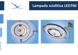
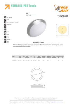
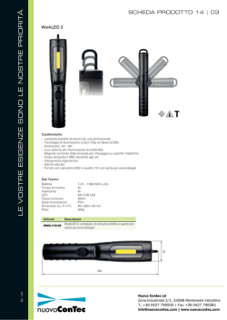
Technische Daten und Montage
Technical Data and Installation
Specificazioni e Montaggio
Elektronischer Riegelschaltkontakt 8501
Electronic Bolt Contact 8501
Chiavistello a contatto elettronico 8501
Anschlüsse Connection Connessione
Abb. 1
Figure 1
Figura 1
Deutsch
1 Schirm
English
Italiano
Grommet shield
Schermo canale del
cavo
2 Sensor Seele
Sensor life
Anima del sensore
3 Sensor Schirm
Sensor shield
Schermo del sensore
4 Minus
Minus (GND)
Negativo
5 +10 ... 15 V DC
+10 ... 15 V DC
+10 ... 15 V DC
6 Verschlussüberwachung
Lock state detection
Controllo serratura
7 Verschlussüberwachung
Lock state detection
Controllo serratura
8 potentialfreier Ausgang
Floating contact
Uscita a potenziale zero
9 potentialfreier Ausgang
Floating contact
Uscita a potenziale zero
10 Deckelkontakt
Tamper contact
Contatto coperchio
11 Deckelkontakt
Tamper contact
Contatto coperchio
12 n.c.
n.c.
n.c.
13 n.c.
n.c.
n.c.
14 n.c.
n.c.
n.c.
15 n.c.
n.c.
n.c.
16 n.c.
n.c.
n.c.
17 Schirm
Grommet shield
Schermo passaggio dei
cavi
Kabeldurchführung
Kabeldurchführung
Anschlussschema Connection diagram Schema di connessione
Deutsch
English
Italiano
A Sensor
Sensor
Sensore
B Alarmzentrale
Control panel
L‘unità centrale
d‘allarme
Group input
Ingresso gruppi
B1 Gruppeneingang
B2 Verschlussüberwachung Lock state detection
Controllo serratura
C Fernanzeigetableau
Remote display
Quadro indicatore a
distanza
D Zusatzrelais
Additional relay
Relais supplementare
E Deckelkontakt
Tamper contact
Contatto coperchio
* • Entfällt bei
• Line not used
• Viene omessa in caso
di connessione a 4 fili
Vierdrahtanschluss
• Gestrichelte Linie
kommt hinzu bei
4-Draht-Anschluss
• Dashed line
additionally needed in • La linea tratteggiata
si aggiunge per la
4-wire installation
connessione a 4 fili
Deutsch
Technische Daten
Ausgänge
Verschlussüberwachung
Potentialfreier Ausgang
A / Schließer
B / Öffner
Betriebsspannung
10 – 15 V DC
Temperaturbereich
-25°C bis +60°C
Stromverbrauch
1 mA (bei verschl. Tür)
3 mA (bei aufgeschl. Tür inkl. LED)
Abmessung Sensor (H x B x T)
20 x 10 x 7 mm
Abmessung Auswerteeinheit
(H x B x T)
51 x 115 x 27 mm
Zulassung
G188037, VdS C
Umweltklasse
Auswerteeinheit
Sensor
II
IV
Montagehinweise:
Der Sensor kann lageunabhängig montiert werden. Er sollte vorzugsweise mit Zylinderkopfschrauben M3 bzw. Karosserieschrauben
befestigt werden.
Der Abstand zwischen Sensorfläche und zugeschlossenem Riegel darf
maximal 3 mm betragen.
Bei Kunststoffriegel muss eine Metallfläche in Form von z.B. Epoxyd
0,5 mm mit 35 µm Cu-Auflage auf den Riegel aufgeklebt werden.
50,5
27,0
Kunststoffgehäuse
mit Sabotageüberwachung
Abschaltbare LED-Anzeige
zur Verschlusskontrolle
114,5
Anschlussleitung 3m
Koax RG 187 A/U
Bohrung 3,2mm
Sackloch für M3
Zylinderkopfschrauben
Vergussmasse WEVO VE
mit Härter WEVO 280
Sensorfläche d=8mm
20,0
10,0
7,0
Deutsch
Bei kleinem Schlosskasten (6) kann der
Sensor (1) seitlich
befestigt werden.
1.......Sensor
2.......Empfindliche Fläche
3.......Anschlusskabel
Hier ist eine stirnseitige Montage
möglich.
Bei sehr tiefem
Schlosskasten (6) kann
der Sensor oberhalb
des Riegels (5) oder auf
Abstandshalter
angeschraubt werden.
4.......Schloss
5.......Riegel
6.......Schlosskasten
Abgleichanweisung:
Tür geschlossen, Schloss aufgeschlossen.
Spannungsmesser mit Ri ≥ 10MΩ am Messpunkt MP1 anschließen
und Riegelkontakt mit Trimmpoti TR auf 0,7 V abgleichen (Abb.1).
Bei Schließen des Schlosses muss sich eine Spannung von ≥ 2,25 V
einstellen, anderenfalls ist der Abstand Sensor <=> Riegel zu groß.
Hinweis:
Der maximale Abstand zwischen Sensor und Riegel darf 3 mm nicht
überschreiten.
Bleibt die Spannung am MP1 im gesamten Einstellbereich ≤ 0,15 V,
so ist der Sensor nicht angeschlossen oder es liegt ein Kabelbruch vor.
Bleibt die Spannung am MP1 im gesamten Einstellbereich ≥ 2,25 V,
so ist der Sensor kurzgeschlossen.
S1 geschlossen:
S1 offen:
MP1 mittl. Anschluss:
R1:
R2:
LED aktiv bei Riegel offen
LED ohne Funktion
Pluspol z. Abgleich
(Masse auf den äußeren Kontakten)
Gruppenwiderstand Deckelkontakt
Gruppenwiderstand Verschlussüberwachung
English
Technical Data
Outputs
Lock state detection
Floating contact
N/O contact
N/C contact
Operating voltage
10 – 15 V DC
Ambient temperature
-25°C to +60°C
Current-consumption
1 mA (with locked door)
3 mA (with unlocked door incl. LED)
Sensor size (W x H x D)
20 x 10 x 7 mm
Evaluation unit size (W x H x D)
51 x 115 x 27 mm
Approvals
G188037, VdS C
Environmental class
Evaluation unit
Sensor
II
IV
Installation advices:
The sensor may be mounted independent of any position. It should
preferably be fixed by a cylinder head screw M3 or thread-forming
screw.
The maximum allowable distance between thesensor´s sensitive area
and the locked bar is 3 mm.
If the lock is equipped with plastic bar a metal area must be gluedon, e.g. an epoxy-plate of 0.5 mm width with 35 µm Cu-plating.
English
50.5
27.0
Plastic housing with
tamper contact
Identification LED
114.5
LED
Sensor wire 3m
coax RG 187 A/U
Hole 3.2mm
Joint sealing compound WEVO VE
with hardener WEVO 280
Sensitive area d=8mm
20.0
Blind hole for
cylinder head screw M3
10.0
7.0
Inside a small lockhousing (6) the sensor
(1) can be installed
besides the bar.
1.......Sensor
2.......Sensitive area
3.......Connection cable
This picture shows
frontal installation.
Inside a very deep or
huge lock-housing (6)
the sensor can be installed above the bar (3) or
lifted with spacers.
4.......Lock
5.......Bolt
6.......Lock-housing
Calibration advice:
Conditions: door closed, lock opened.
Connect voltmeter with Ri ≥ 10MΩ to measuring point MP1 and calibrate
the lock detector with trimmer TR to 0.7 V (figure 1).
Voltage must rise above ≥ 2.25 V after closing the lock-bar, otherwise
check if the distance between sensor and bar is too far.
Hint:
Maxiumum distance between sensor and bar is 3 mm. If voltage at MP1
stays below ≤ 0.15 V for the whole tuning-range, either the sensor is not
connected or the connection wire is broken.
If voltage at MP1 stays above ≥ 2.25 V for the whole tuning-range, the
sensor is shorted.
S1 closed:
S1 open:
MP1 middle contact:
R1:
R2:
LED on when bar open
LED disabled
positive pole für calibration
(ground on each outer contact)
group-resistor tamper-contact
group-resistor lock state detection
Italiano
Specificazioni
Uscite
Controllo serratura
Uscita a potenziale zero
Contatto di funzionamento
Contatto di apertura
Tensione di funzionamento
10 – 15 V DC
Intervallo temperatura
-25°C a +60°C
Consumo corrente
compr. LED
1 mA (con porta chiusa)
3 mA (con porta aperta)
Dimensioni sensore (A x L x P)
20 x 10 x 7 mm
Dimensioni unità di riconoscimento (A x L x P)
51 x 115 x 27 mm
VdS-Controllo
G188037, VdS C
Classe ambientale
Unità di riconoscimento
Sensore
II
IV
Indicazioni per il montaggio:
Il sensore può essere montato indipendente dall’ubicazione. Preferibilmente fissarlo con viti a testa cilindrica M3 o da carrozzeria.
La distanza tra le superfici del sensore e del chiavistello chiuso deve
ammontare a 3 mm.
Se il chiavistello è in plastica incollate sul chiavistello una superficie metallica in forma, ad esempio eposside da 0,5 mm con uno strato da 35 µm Cu.
50,5
27,0
Custodia in materiale plastico
con controllo sabotaggio
Visualizzatore LED disattivabile
per il controllo della serratura
114,5
Linea di connessione
3m Koax RG 187 A/U
Perforazione 3,2 mm
Materiale di sigillatura WEVO VE
con indurente WEVO 280
Superficie del sensore 8mm
20,0
Foro cieco per viti a
testa cilindrica M3
10,0
7,0
Se la cassetta per la
serratura (6) è piccola,
il sensore (1) può
essere fissato di lato.
In questo caso è possibile un montaggio
frontale.
1.......Sensore
2.......Superficie sensibile
3.......Cavo di connessione
Se la cassetta per la
serratura (6) fosse molto
profonda, il sensore
può essere avvitato al di
sopra del chiavistello (5)
o sul distanziatore.
4.......Serratura
5.......Chiavistello
6.......Cassetta della serratura
Istruzioni per la regolazione :
Porta chiusa, serratura aperta.
Collegate il tester con Ri ≥ 10MΩ al punto di misura MP1 e regolate il
contatto del chiavistello con il trimmer potenziometrico su 0,7 V (figura 1).
Alla chiusura della serratura deve impostarsi una tensione ≥ 2,25 V, in
caso contrario la distanza sensore <=> chiavistello è troppo ampia.
Indicazioni:
La distanza massima tra il sensore e il chiavistello non deve
oltrepassare i 3 mm.
Se la tensione MP1 nell’area totale di impostazione rimane ≤ 0,15 V,
il sensore non è collegato oppure potrebbe esservi una fenditura nel
cavo.
Se la tensione MP1 nell’area totale di impostazione rimane ≥ 2,25 V, il
sensore è in cortocircuito.
S1 chiuso:
S1 aperto:
MP1 media connessione:
R1:
R2:
LED attivo sul chiavistello aperto
LED senza funzione
Regolazione del polo positivo
(la massa sul contatto esterno)
Resistenza gruppo contatto di copertura
Resistenza gruppo controllo della serratura
Telefon: Fax: +49 (0) 6033-97404-0
+49 (0) 6033-97404-20
E-Mail: Internet: [email protected]
www.link-gmbh.com
Technische Änderungen vorbehalten / Specifications subject to change without notice / Riserva di modifiche tecniche
LINK GmbH
D - 35510 Butzbach
MA0001860
Stand / Valido dal: 02/14
© Copyright 2026 Paperzz