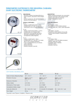
Art. 74508
COLLEGAMENTO:
A
B
C
D
ISTRUZIONI DI MONTAGGIO
Centralina
Display
IMPORTANTE:
E
Questo sistema deve essere considerato come un aiuto per la retromarcia e non deve essere inteso come
una sostituzione delle responsabilità del guidatore nella fase di retromarcia. Abilità di guida, come and
esempio rallentare, utilizzare gli specchietti retrovisori ecc. sono sempre essenziali.
1
2
3
4
5
F
Questo prodotto è idoneo solamente per veicoli con sistema elettrico a 12V.
L’installazione deve essere effettuata da un elettrauto o da personale esperto.
Posizionare i cavi lontano da forti fonti di calore e componenti elettrici.
Si consiglia di controllare la posizione dei sensori prima di effettuare i fori.
Dopo l’installazione, testare le funzioni prima di mettersi alla guida.
CARATTERISTICHE:
•
•
•
•
•
•
•
A
A
B
B
C
C
D
D
G
E
H
F
Sensore posteriore
Sensore posteriore
Sensore posteriore
Sensore posteriore
Sensore anteriore
Sensore anteriore
Centralina
Raggio di scansione: da 1,5m a 0,2m in profondità e 0,8 m in altezza
Display che indica la distanza dall’oggetto. 14 tacche luminose, 7 per lato
Avvisatore acustico.
Consumo durante il funzionamento: 4w
Voltaggio: 12 Volt.
Resistente a temperature estreme: -30°C / +70°C
Perfette prestazioni in ogni condizione meteorologica
Display e avvisatore acustico
Rosso
Retromarcia (+)
Bianco
Freno (+)
Nero
Massa (-)
CENTRALINA
PUNTA A TAZZA
RAGGIO DI LETTURA DEI SENSORI:
DISPLAY E
AVVISATORE ACUSTICO
SENSORI
ANTERIORI
SENSORI
POSTERIORI
INSTALLAZIONE:
Prima di effettuare l’installazione sul veicolo, collegare tutti i componenti in modo da
verificare la compatibilità elettrica. Effettuare il test sia a motore spento che acceso.
In caso di problemi scrivere a: [email protected]
1
2
3
4
5
6
Per un funzionamento ottimale, i sensori dovrebbero essere
installati ad una altezza da terra tra 60 e 80 cm circa.
Con un metro a nastro e un pennarello delebile, misurare
10-12 cm dall’angolo destro del paraurti e segnare
la posizione di montaggio del sensore.
Ripetere la stessa operazione misurando dall’angolo sinistro
e segnando alla stessa distanza.
Dopo aver individuato la posizione dei 2 sensori laterali,
individuare la distanza dei 2 sensori centrali misurando
la distanza tra i 2 punti laterali e dividendo per 3. Esempio:
se i due sensori laterali distano 180 cm l’uno dall’altro,
la distanza dei 2 sensori centrali deve essere di 60 cm
(180:3=60 cm).
Installare la punta a fresa (in dotazione) su un qualsiasi
trapano o avvitatore e praticare il foro in corrispondenza
dei 4 punti precedentemente segnati con il pennarello.
La centralina deve essere posizionata all’interno del veicolo
in posizione protetta da calore eccessivo, umidità e spruzzi
d’acqua.
Il display digitale a led contiene anche l’avvisatore acustico
e deve essere posizionato sul cruscotto in una posizione
facilmente visibile ed udibile.
Distanza
Illuminazione Display
Segnale acustico
SICURO
ALLERTA
LIMITE
150 - 100 cm
Led verde
BIP - BIP - BIP
100 - 40cm
Led arancione
BIP - BIP - BIP - BIP
40 - 0cm
Led rosso
BIIIIIIIIIIIP
ATTENZIONE
Falsi rilevamenti possono avvenire nei seguenti casi:
50~80
cm
superfici inclinate
e lisce
1
3
L
1
3
L
1
3
L
superfici rotonde
e lisce
Oggetti fonoassorbenti
come cotone e spugna
Superfici con forme
particolari o sporgenti
Ambientazioni
particolari
• dopo l’installazione, testare il sistema prima dell’utilizzo
• forti piogge, sporco o sensori danneggiati possono causare rilevamenti errati
• assicurarsi che i sensori funzionino correttamente prima di effettuare la retromarcia
L
POSSIBILI CAUSE E SOLUZIONI
Montare il sensore in modo
errato può comportare un falso
allarme.
1
•
•
•
•
Il display non fornisce alcuna segnalazione:
il cavo d’alimentazione è stato collegato correttamente?
La chiave è inserita ed il quadro sotto tensione?
La retromarcia è stata inserita?
I fili sono stati collegati correttamente?
2
•
•
•
•
•
False segnalazioni dal display quando la retromarcia non è inserita:
Controllare che il cavo di alimentazione della centralina sia connesso al cavo della luce di retromarcia
Il cavo della luce di retromarcia è collegato correttamente al cavo del display?
Controllare che la superficie del sensore sia pulita
Controllare che i sensori siano collegati correttamente alla centralina
Controllare se i cavi dei sensori sono danneggiati
3 La posizione dell’oggetto non corrisponde all’indicatore del display:
• I sensori sono collegati alla centralina nell’ordine corretto? Ex. A.B.C.D.
uguale
I fori dei sensori devono essere
in posizione perfettamente
orizzontale su una superficie di
applicazione completamente
liscia.
Con un pennarello delebile,
segnare le posizioni dei sensori.
Verificare che dietro al paraurti
non ci siano piastre di fissaggio,
cavi o altri ostacoli.
Condizioni
particolari
I sensori parcheggio sono considerati come prodotto di supporto per il conducente.
Non c’é nessuna garanzia che il prodotto possa condizionare l’efficienza del conducente o prevenire incidenti.
Importante: installare i sensori
verticalmente, con la scritta
“UP” rivolta verso l’alto.
up
Livello sicurezza
Verificare che la punta a tazza
sia dello stesso diametro dei
sensori.
4
•
•
•
•
A retromarcia inserita il display indica 0,5 o 0,6 m:
C’è un ostacolo entro 0,6m
I sensori sono installati troppo in basso ovvero verso il terreno?
Controllare che i sensori non siano installatial contrario
Staccare un sensore alla volta e controllare il segnale
Se il problema persiste contattare il rivenditore o l’ufficio tecnico Tel: 0375 820700
oppure inviate le vostre domande via mail: [email protected] Vi risponderemo il prima possibile.
Art. 74508
CONNECTION:
A
B
C
MOUNTING INSTRCTIONS
ECU
D
Display
WARNING:
E
This parking assist system is designed as a reversing aid. It is not a substitute of driver's responsibilities
normally assumed when reversing. Lampa does not liable for any damages caused by reversing only rely
on this system. Proper driving skills, such as slow down, use of mirror or lookout etc. is always essential.
1
2
3
4
5
F
This unit is for vehicles with 12V DC only
Please install this unit by a professional technician.
Avoid high temperature and high voltage while laying out the wire harness.
Wire connection point should be insulated.
Conduct test after finishing the installation.
SPECIFICATIONS:
•
•
•
•
•
•
•
ECU
Detection range 1,5m - 0,2m horizontally, 0,8 m vertically
The display shows the distance from the object. 14 led, 7 on the left and 7 on the right.
Acustic alarm.
Input: 4w
Voltage: 12 Volt.
Perfect performance in all weather conditions : -30°C / +70°C
Heavy rainproof design.
A
A
B
B
C
C
D
D
Back sensor
G
E
Front sensor
H
F
Back sensor
Back sensor
Front sensor
Display and alarm
Red
Reversing (+)
White
Break (+)
Black
ECU
Back sensor
Ground Wire (-)
HOLE SAW
DETECTION RANGE:
DISPLAY
AND SPEAKER
FRONT
SENSORS
BACK
SENSORS
Safety level
SAFE
ALERT
LIMIT
INSTALLATION:
We warmly recommend to connect all the components and test the electric compatibility
BEFORE installing the parking sensors on the vehicle. Carry out a check both with the engine off
and on. In case of problems, please mail to: [email protected]
1 Place the sensors between 50 and 80 cm from the ground to
grant a correct working. Minimum distance between the
sensors should be not less than 30 cm and not more than 80
cm. We recommend to keep the same distance between the
sensors in order to enable a perfect functioning of the device.
2 Use a measuring tape and an erasable marker to mark the
position of the first sensor at 10-12 cm of distance from the
right corner of the rear bumper. Repeat the same operation
with the left corner.
3 Measure the distance between the two side sensors and divide
it by three to find out the location for the two central sensors.
Example: if the length between the side sensors is 180 cm, the
distance of the two central sensors must be 60 cm (180:3=60 cm).
4 Mount the drill (included in the mounting kit) on a wrench and
drill into the four points previously marked on the rear
bumper.
5 Control unit must be placed inside the vehicle, to protect it
from heat, wet and water sprinkles.
6 The display must be placed in a suitable position on the
dashboard for a perfect visibility and audibility.
150 - 80 cm
Green light
BIP - BIP - BIP
80 - 40cm
Orange light
BIP - BIP - BIP - BIP
40 - 20cm
Red light
BIIIIIIIIIIIIIIIIIIIIIIIIIIP
NOTICE
Misleading detection may occur in the following situations:
Smooth sloping
surface
50~80
cm
1
3
L
1
3
L
1
3
L
To mount the sensor in the
wrong way can cause false
detections.
Items absorbing sound,
e.g. cotton
Similar special
obstacle
Similar special
situation
Similar special
environment
After installation, check if the system is in order before use
Heavy rain, dirt or damaged sensor could cause incorrect detection.
Ensure the system is in order before use.
Ensure that there is no false alarm when the vehicle is reversing.
The product is a driver assistance device. No warranty as to the operating efficient of the system
or prevention of accidents is guaranteed.
L
Important: The sensor must be
installed vertically with the "up"
sign upside.
up
•
•
•
•
Smooth round
obstacle
TROUBLESHOOTING
1
•
•
•
After the installation the display doesn’t work:
Are all wires connected properly?
Is the vehicle ACC ON?
Is the reversing gear engaged (the reversing light should turn on);
2
•
•
•
•
Damaged sensor detected:
Are all sensors plugged into the ECU correctly and tightly?
Is the sensor wire broken?
Is the sensor covered by mud or snow?
Is the sensor damaged?
3 False warning:
• Are all sensors plugged into the ECU in the correct position tightly?
• Does any sensor detect the ground?
same size
The positions of the holes must
be vertical and even.
Measure and position the sensors'
locations.
Check the size of the hole
saw to be compatible to the
diameter of the sensor.
4 When the reversing gear is engaged, the display always shows 0.5m or 0.6m:
• Is the sensor mounting too low or facing to the ground?
• Is sensor mounted upside-down?
If the problem persists contact your dealer or write us at: [email protected] or call our office: +39 0375 820700
We will gladly help you.
© Copyright 2026 Paperzz