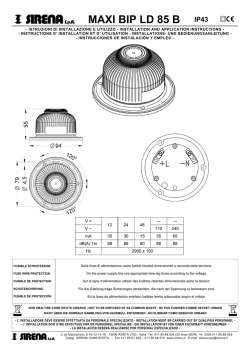
Deutsch
Einbauanleitung
Absorber-Kühlschrank für Freizeitfahrzeuge
RMD 8501
RMD 8551
N 2
MBA 07/2012
RMD 8505
RMD 8555
DE
Dometic GmbH
In der Steinwiese 16
D-57074 Siegen
www.dometic.com
© Dometic GmbH - 2012 - Änderungen vorbehalten
2
Inhaltsverzeichnis
1.0
Allgemeines . . . . . . . . . . . . . . . . . . . . . . . . . . . . . . . . . . . . . . . . . . .
4
1.1
1.2
1.3
1.4
1.5
1.6
1.7
Einleitung . . . . . . . . . . . . . . . . . . . . . . . . . . . . . . . . . . . . . . . . . . . . . . . . . . . . . . . . . . . . . . . . . .
Hinweise zu dieser Bedienungsanleitung . . . . . . . . . . . . . . . . . . . . . . . . . . . . . . . . . . . . . . . . .
Urheberschutz . . . . . . . . . . . . . . . . . . . . . . . . . . . . . . . . . . . . . . . . . . . . . . . . . . . . . . . . . . . . . .
Erklärung der verwendeten Symbole . . . . . . . . . . . . . . . . . . . . . . . . . . . . . . . . . . . . . . . . . . . . .
Gewährleistung . . . . . . . . . . . . . . . . . . . . . . . . . . . . . . . . . . . . . . . . . . . . . . . . . . . . . . . . . . . . .
Haftungsbeschränkung . . . . . . . . . . . . . . . . . . . . . . . . . . . . . . . . . . . . . . . . . . . . . . . . . . . . . . .
Konformitätserklärung . . . . . . . . . . . . . . . . . . . . . . . . . . . . . . . . . . . . . . . . . . . . . . . . . . . . . . . .
4
4
4
4
5
5
5
2.0
Sicherheitshinweise . . . . . . . . . . . . . . . . . . . . . . . . . . . . . . . . . . . . .
6
2.1
2.2
2.3
2.4
Bestimmungsgemäße Verwendung . . . . . . . . . . . . . . . . . . . . . . . . . . . . . . . . . . . . . . . . . . . . . .
Verantwortung des Nutzers . . . . . . . . . . . . . . . . . . . . . . . . . . . . . . . . . . . . . . . . . . . . . . . . . . . .
Arbeiten und Überprüfungen am Kühlschrank . . . . . . . . . . . . . . . . . . . . . . . . . . . . . . . . . . . . .
Betreiben des Kühlschrankes mit Gas . . . . . . . . . . . . . . . . . . . . . . . . . . . . . . . . . . . . . . . . . . . .
6
6
6
6
3.0
Modellbeschreibung . . . . . . . . . . . . . . . . . . . . . . . . . . . . . . . . . . . .
7
3.1
3.2
3.3
Modellbezeichnung . . . . . . . . . . . . . . . . . . . . . . . . . . . . . . . . . . . . . . . . . . . . . . . . . . . . . . . . . .
Typenschild des Kühlschranks . . . . . . . . . . . . . . . . . . . . . . . . . . . . . . . . . . . . . . . . . . . . . . . . . .
Technische Daten . . . . . . . . . . . . . . . . . . . . . . . . . . . . . . . . . . . . . . . . . . . . . . . . . . . . . . . . . . . .
7
7
8
4.0
Einbauanleitung . . . . . . . . . . . . . . . . . . . . . . . . . . . . . . . . . . . . . . . .
9
4.1
Einbau . . . . . . . . . . . . . . . . . . . . . . . . . . . . . . . . . . . . . . . . . . . . . . . . . . . . . . . . . . . . . . . . . . . .
9
4.1.1
4.1.2
4.1.3
Seitlicher Einbau . . . . . . . . . . . . . . . . . . . . . . . . . . . . . . . . . . . . . . . . . . . . . . . . . . . . . . . . . . . . . . . . . . . . .
Heckeinbau . . . . . . . . . . . . . . . . . . . . . . . . . . . . . . . . . . . . . . . . . . . . . . . . . . . . . . . . . . . . . . . . . . . . . . . . .
Zugdichter Einbau . . . . . . . . . . . . . . . . . . . . . . . . . . . . . . . . . . . . . . . . . . . . . . . . . . . . . . . . . . . . . . . . . . .
9
10
10
12
4.2
Einbaunische . . . . . . . . . . . . . . . . . . . . . . . . . . . . . . . . . . . . . . . . . . . . . . . . . . . . . . . . . . . . . . .
4.2.1
Aufstellen in der Nische . . . . . . . . . . . . . . . . . . . . . . . . . . . . . . . . . . . . . . . . . . . . . . . . . . . . . . . . . . . . . . .
11
4.3
Be- und Entlüftung . . . . . . . . . . . . . . . . . . . . . . . . . . . . . . . . . . . . . . . . . . . . . . . . . . . . . . . . . .
12
4.3.1
4.3.2
Be- und Entlüftung des Kühlschranks . . . . . . . . . . . . . . . . . . . . . . . . . . . . . . . . . . . . . . . . . . . . . . . . . . . .
Ventilationshöhen . . . . . . . . . . . . . . . . . . . . . . . . . . . . . . . . . . . . . . . . . . . . . . . . . . . . . . . . . . . . . . . . . . . .
12
13
4.4
Einbau der Lüftungssysteme . . . . . . . . . . . . . . . . . . . . . . . . . . . . . . . . . . . . . . . . . . . . . . . . . . .
14
4.4.1
4.4.2
Einbau LS300 . . . . . . . . . . . . . . . . . . . . . . . . . . . . . . . . . . . . . . . . . . . . . . . . . . . . . . . . . . . . . . . . . . . . . . .
Einbau Dachentlüfter R500 . . . . . . . . . . . . . . . . . . . . . . . . . . . . . . . . . . . . . . . . . . . . . . . . . . . . . . . . . . . . .
14
14
4.5
4.6
4.7
4.8
4.9
Abgasführung . . . . . . . . . . . . . . . . . . . . . . . . . . . . . . . . . . . . . . . . . . . . . . . . . . . . . . . . . . . . . .
Kühlschrankbefestigung . . . . . . . . . . . . . . . . . . . . . . . . . . . . . . . . . . . . . . . . . . . . . . . . . . . . . . .
Einsetzen der Dekorplatte . . . . . . . . . . . . . . . . . . . . . . . . . . . . . . . . . . . . . . . . . . . . . . . . . . . . .
Gasinstallation . . . . . . . . . . . . . . . . . . . . . . . . . . . . . . . . . . . . . . . . . . . . . . . . . . . . . . . . . . . . . .
Elektrische Installation . . . . . . . . . . . . . . . . . . . . . . . . . . . . . . . . . . . . . . . . . . . . . . . . . . . . . . . .
15
15
16
17
18
4.9.1
4.9.2
4.9.3
4.9.4
4.9.5
Netzanschluss . . . . . . . . . . . . . . . . . . . . . . . . . . . . . . . . . . . . . . . . . . . . . . . . . . . . . . . . . . . . . . . . . . . . . . .
Batterieanschluss . . . . . . . . . . . . . . . . . . . . . . . . . . . . . . . . . . . . . . . . . . . . . . . . . . . . . . . . . . . . . . . . . . . .
Kabelanschlüsse . . . . . . . . . . . . . . . . . . . . . . . . . . . . . . . . . . . . . . . . . . . . . . . . . . . . . . . . . . . . . . . . . . . . .
D+ und Solaranschluss . . . . . . . . . . . . . . . . . . . . . . . . . . . . . . . . . . . . . . . . . . . . . . . . . . . . . . . . . . . . . . . .
Schaltschema . . . . . . . . . . . . . . . . . . . . . . . . . . . . . . . . . . . . . . . . . . . . . . . . . . . . . . . . . . . . . . . . . . . . . . .
18
19
19
21
22
3
Allgemeines
1.0 Allgemeines
1.1
1.4
Einleitung
Beim Einbau des Gerätes müssen die technischen und administrativen Vorschriften des
Landes, in dem das Fahrzeug zum ersten Mal
zugelassen wird, beachtet werden.
Ansonsten sind die Einbauvorschriften des
Herstellers zu beachten. In Europa z.B. müssen Gasgeräte, Leitungsverlegung, Gasflaschenaufstellung
sowie Abnahme und
Dichtheitsprüfung der Europäischen Norm EN
1949 für Flüssiggasanlagen in Fahrzeugen
entsprechen.
Erklärung der verwendeten
Symbole
Warnhinweise
Warnhinweise sind durch Symbole gekennzeichnet. Ein ergänzender Text erläutert Ihnen
den Grad der Gefährdung.
Beachten Sie diese Warnhinweise sehr
genau. Damit schützen Sie sich, andere
Personen und das Gerät vor Schäden.
GEFAHR!
1.2
Hinweise zu dieser
Installationsanleitung
GEFAHR kennzeichnet eine unmittelbare
Gefahrensituation, die zum Tod oder einer ernsten Verletzung führen kann, wenn die angegebenen Anweisungen nicht befolgt werden.
Bevor Sie den Kühlschrank einbauen, lesen
Sie diese Installationsanleitung bitte sorgfältig durch.
WARNUNG!
Diese Anleitung gibt Ihnen die nötigen
Hinweise für den richtigen Einbau Ihres
Kühlschrankes. Beachten Sie besonders die
Sicherheitshinweise. Die Einhaltung der
Hinweise und Handlungsanweisungen ist
wichtig und schützt Sie und den Kühlschrank
vor Schäden. Das Gelesene muss verstanden
worden sein, bevor Sie eine Maßnahme durchführen.
WARNUNG kennzeichnet eine mögliche
Gefahrensituation, die zum Tod oder einer ernsten Verletzung führen kann, wenn die angegebenen Anweisungen nicht befolgt werden.
VORSICHT!
Bewahren Sie diese Installationsanleitung
sorgfältig auf, sodass sie jederzeit verwendet werden kann.
1.3
VORSICHT kennzeichnet eine mögliche
Gefahrensituation, die zu leichten oder mittleren Verletzungen führen kann, wenn die angegebenen Anweisungen nicht befolgt werden.
Urheberschutz
VORSICHT!
Die Angaben, Texte und Abbildungen in dieser
Anleitung sind urheberrechtlich geschützt und
unterliegen den gewerblichen Schutzrechten.
Kein Teil dieser Anleitung darf ohne die schriftliche Genehmigung der Dometic GmbH,
Siegen, reproduziert, kopiert oder sonstwie
verwendet werden.
VORSICHT ohne Sicherheitssymbol kennzeichnet eine mögliche Gefahrensituation, die zu
Beschädigungen des Gerätes führen kann,
wenn die angegebenen Anweisungen nicht
befolgt werden.
4
Allgemeines
Information
1.6
Haftungsbeschränkung
Alle Angaben und Hinweise in dieser Einbauanleitung wurden unter Berücksichtigung geltender Normen und Vorschriften sowie dem
Stand der Technik erstellt. Dometic behält
sich vor, jederzeit Änderungen am Produkt
vorzunehmen, die im Interesse der
Verbesserung des Produktes und der
Sicherheit angebracht sind.
Dometic übernimmt keine Haftung für
Schäden bei :
INFORMATION gibt Ihnen ergänzende und
nützliche Hinweise zum Umgang mit Ihrem
Kühlschrank.
Umwelthinweis
Nichtbeachtung dieser Anleitung
nicht bestimmungsgemäßer Verwendung
Verwendung von nicht originalen
Ersatzteilen
UMWELTHINWEIS
gibt Ihnen nützliche
Hinweise
zur
Energieeinsparung
und
Entsorgung des Gerätes.
Veränderungen und Eingriffen am Gerät
Einwirkung von Umgebungseinflüssen, wie
- Temperaturänderungen
- Luftfeuchtigkeit
1.5
1.7
Gewährleistung
Gewährleistungsabwicklungen erfolgen nach
der europäischen Richtlinie 44/1999/EC und
den landesüblichen Bedingungen. Im
Gewährleistungs- oder Servicefall wenden Sie
sich bitte an unseren Kundendienst.
Störungen, die auf fehlerhafte Bedienung
zurückzuführen sind, unterliegen nicht der
Gewährleistung. Jede Veränderung am Gerät
oder die Verwendung von Ersatzteilen, die
keine Original - Dometic - Ersatzteile sind,
sowie das Nichteinhalten der Einbau- und
Bedienungsanleitung führt zum Erlöschen der
Gewährleistung und zum Ausschluss von
Haftungsansprüchen.
5
Konformitätserklärung
Sicherheitshinweise
2.0 Sicherheitshinweise
2.1
Bestimmungsgemäße
Verwendung
GEFAHR!
Überprüfen Sie niemals gasführende Teile
und Leitungen mit einer offenen Flamme auf Undichtigkeit !
Es besteht Brand- oder Explosionsgefahr.
Dieser Kühlschrank ist für den Einbau in
Freizeitfahrzeuge wie Wohnwagen oder
Reisemobile vorgesehen. Das Gerät ist für
diese Anwendung in Konformität mit der EUGasgeräterichtlinie baumustergeprüft.
Benutzen Sie den Kühlschrank ausschließlich
zum Kühlen und Lagern von Lebensmitteln.
WARNUNG!
Öffnen Sie niemals das Absorberkühlaggregat ! Es steht unter hohem Druck.
VORSICHT!
Der Kühlschrank darf nicht dem Regen
ausgesetzt werden.
2.2
Es besteht Verletzungsgefahr!
Verantwortung des Nutzers
2.4
Personen, die den Kühlschrank bedienen,
müssen mit dem sicheren Umgang vertraut
sein und die Hinweise der Bedienungsanleitung kennen.
2.3
Betreiben des Kühlschranks
mit Gas
Der Betriebsdruck muss unbedingt der
Angabe
auf
dem
Typenschild
des
Kühlschranks entsprechen. Vergleichen Sie
die Angabe des Betriebsdruckes auf dem
Typenschild
mit
den
Daten
des
Druckminderers an der Flüssiggasflasche.
Arbeiten und Überprüfungen
am Kühlschrank
WARNUNG!
Arbeiten an den Gas-, Abgas- und
Elektroeinrichtungen dürfen nur von autorisierten Fachkräften ausgeführt werden.
Durch nicht fachgerechte Maßnahmen
können erhebliche Sach- und / oder
Personenschäden entstehen.
6
Modellbeschreibung
3.0 Modellbeschreibung
3.1
3.2
Modellbezeichnung
Typenschild des Kühlschranks
Beispiel :
RM D
Im Inneren des Kühlschranks finden Sie das
Typenschild des Kühlschranks. Es enthält alle
wichtigen Angaben zum Kühlschrank. Dort
können Sie die Modellbezeichnung, die
Produktnummer und Seriennummer ablesen.
Diese Angaben benötigen Sie bei allen
Kontakten mit dem Kundendienst oder der
Ersatzteilbestellung.
8501
1
5
Gerätetiefe :
0 = Standard
5 = + 55mm
6 = + 65mm
1
5 = Breite 523mm
2
3
Modellreihe
4
5
Zweitüriger Kühlschrank
Refrigerator Mobile /
Mobiler Absorberkühlschrank
Beispiel
1
manuelle
Energiewahl,
Zündung (MES)
automatische
5
automatische und manuelle Energiewahl,
automat. Zündung (AES)
7
1
Modellnummer
2
Produktnummer
3
Seriennummer
4
Elektrische Anschlusswerte
5
Gasdruck
Abb. 1
Modellbeschreibung
3.3
Technische Daten
RMD 8xxx
H
T
B
Abb. 2
Modell
Abmessungen
H x B x T (mm)
Tiefe inkl. Tür
Bruttoinhalt
mit
Frosterfach
Frosterfach
Anschlusswerte
Netz/Batterie
Verbrauch *
Elektro/Gas
in 24h
Nettogewicht
Zündung
Piezo Automat
RMD 8501
1245x523x567
160 lit.
30 lit.
190 W / 170 W
ca.3,2 KWh / 380 g
40 kg
•
RMD 8505
1245x523x567
160 lit.
30 lit.
190 W / 170 W
ca.3,2 KWh / 380 g
40 kg
•
1245x523x622
190 lit.
35 lit.
190 W / 170 W
ca.3,2 KWh / 380 g
41.5 kg
•
1245x523x622
190 lit.
35 lit.
190 W / 170 W
ca.3,2 KWh / 380 g
41.5 kg
•
RMD 8551
RMD 8555
Technische Änderungen vorbehalten.
*Durchschnittsverbrauch gemessen bei einer durchschnittlichen Umgebungstemperatur von 25°C in Anlehnung an ISOStandard.
8
Einbau
4.0 Einbauanleitung
4.1
4.1.1 Seitlicher Einbau
Einbau
Wird das Gerät auf der Seite der Eingangstür
eingebaut, ist darauf zu achten, dass die
Belüftungsgitter nicht durch die aufstehende
Tür zugedeckt werden. (Abb. 3 Abstand Tür Belüftungsgitter min. 25 mm). Ansonsten entsteht eine eingeschränkte Belüftung, die zu
Kühlleistungsverlusten führt. Die Türseite des
Fahrzeugs wird oft mit einem Vorzelt versehen.
Dadurch
wird
die
Ableitung
von
Verbrennungsgasen und Wärme durch die
Lüftungsgitter erschwert (Kühlleistungsverlust entsteht)!
WARNUNG!
Die Installation des Gerätes darf nur von
autorisiertem Fachpersonal erfolgen!
Das Gerät und die Abgasführung müssen
grundsätzlich so eingebaut werden, dass es
für Servicearbeiten gut zugänglich ist, leicht
aus- und eingebaut und ohne großen Aufwand
aus dem Fahrzeug entnommen werden kann.
Bei der Aufstellung und dem Anschluss des
Gerätes sind folgende Bestimmungen zu
beachten:
(Abb. 3) Die Lüftungsgitter sind abgedeckt.
Der Abstand zwischen der Tür und den
Lüftungsgittern muss min. 25 mm betragen!
Die elektrische Installation muss nach
den nationalen und örtlichen Vorschiften
erfolgen.
Bei Abständen Tür/Gitter zwischen 25 mm
und 45 mm empfehlen wir den Einbau des
Dometic Lüfterkits (Artikel-Nr. 241 2985 00/0) , um eine optimale Kühlleistung bei
hohen Umgebungstemperaturen zu erreichen.
Die Gas-Installation muss nach den
nationalen und örtlichen Vorschiften
erfolgen.
Europäische Norm EN 1949
Europäische Norm EN 60335-1,
EN 60335-2-24, EN 1648-1 , EN 1648-2
Installieren Sie das Gerät geschützt
gegen übermässige Wärmeeinstrahlung.
Überhöhte Wärmeeinstrahlung führt zu Leistungseinbußen und erhöhtem Energieverbrauch des Kühlschrankes !
Abb. 3
Die Lüftungsgitter bieten auch bei geöffneter
Tür einen ungehinderten Austritt der Aggregatwärme und der Abgase (Abb. 4).
Abweichungen von dieser Einbauanweisung ohne vorherige Freigabe von Dometic
führen zum Erlöschen der Gewährleistung
seitens der Dometic GmbH !
Lüftungsgitter frei !
OK!
Abb. 4
9
Einbau
4.1.2 Heckeinbau
VORSICHT!
Der Heckeinbau führt oftmals zu einer ungünstigen Einbausituation, da die optimale Beund Entlüftung nicht immer gewährleistet ist
(z.B. wird das untere Lüftungsgitter durch den
Stoßfänger oder die Rückleuchten des
Fahrzeuges verdeckt !) Die maximale
Kühlleistung des Aggregates ist effektiv nicht
verfügbar.
Die maximale Kühlleistung ist nicht verfügbar! Wenden Sie diese Einbaumöglichkeit nicht an, da bei diesr Einbausituation die Be- und Entlüftung, wie unter
Punkt 4.2 beschrieben, nicht gewährleistet ist!
4.1.3 Zugdichter Einbau
Kühlgeräte in Wohnwagen, Reisemobilen oder
sonstigen Fahrzeugen müssen zugdicht eingebaut sein (EN 1949). Das bedeutet, dass die
Verbrennungsluft für den Gasbrenner nicht aus
dem Wohnraum entnommen wird und die
Abgase am direkten Eintritt in den Wohnraum
gehindert werden.
Lüftungsgitter
frei !
OK!
Abb. 5
Es muss eine geeignete Abdichtung zwischen
dem rückseitigen Bereich des Kühlschranks
und dem Fahrzeuginnenraum vorgesehen
werden.
Eine ungünstige Variante des Heckeinbaus ist
die seitliche Anbringung der Be- und
Entlüftungsgitter (Abb. 6). Die Luft- Wärme Umwäl-zung ist sehr eingeschränkt, wodurch
die Wärmetauscher (Kondenser, Absorber)
nicht mehr ausreichend gekühlt werden. Auch
die Variante mit einem zusätzlich im Boden
montierten Belüftungsgitter weist hier eine
schlechte Luftstromführung auf.
Dometic empfiehlt dringend, dies mittels einer
flexiblen Dichtung auszuführen, um einen späteren Aus- und Einbau des Gerätes zu
Wartungszwecken zu vereinfachen.
WARNUNG!
In keinem Fall soll der zugdichte Einbau
des Kühlschranks mit dauerhaftenden
Dichtungsmassen oder Verschäumung (z.
B. Montageschaum) o. ä. erfolgen!
Verwenden Sie KEINE leicht entflammbaren Materialien (besonders SilikonDichtungsmasse oder ähnliches) zur
Abdichtung, es besteht Brandgefahr! Bei
deren Verwendung erlischt die Produkthaftung und Gewährleistung des Geräteherstellers.
Abb. 6
10
Einbau
Vorschlag 1
Vorschlag 2
Die Lippendichtungen (1) werden in der
Einbaunische unten und jeweils seitlich angebracht (Abb. 7 - 9). Ein Wärmeableitblech (2)
wird in der Einbaunische oberhalb des Kühlschranks befestigt (NICHT am Kühlschrank
befestigen).
Befestigen Sie die Dichtlippen an einer rückseitigen Anschlagsleiste (1), z.B. durch
Kleben.
1
Bringen Sie das Ableitblech so an, dass die
erwärmte Luft durch das obere Lüftungsgitter
ins Freie entweicht und kein Wärmestau entstehen kann.
Der Kühlschrank wird später von vorne in die
Einbaunische eingeschoben. Achten Sie darauf, dass die Dichtungen gleichmäßig am
Gehäuse anliegen.
Der Ausbau des Kühlschranks zur Wartung
und Reparatur ist so leicht möglich
Abb. 10
Der Raum, der sich zwischen Fahrzeugaussenwand und Kühlschrank befindet, ist gegenüber dem Wohnbereich abgedichtet. Es können keine Abgase in den Wohnbereich eindringen. Die Abgase entweichen durch das obere
Gitter der Be- und Entlüftung ins Freie.
2
Es ist beim zugdichten Einbau nicht erforderlich, eine spezielle Abgasführung einzusetzen.
Abb. 8
1
2
Abweichungen bedürfen der Zustimmung
des Herstellers !
1
Abb. 7
Abb. 9
11
Einbau
4.2
Einbaunische
4.3
Der Kühlschrank muss in eine Nische zugdicht eingebaut werden. Der Nischenboden
muss eben sein, sodass das Gerät sich leicht
in seine richtige Lage einschieben lässt. Der
Boden muss genügend Festigkeit haben um
das Gewicht des Gerätes tragen zu können.
Be- und Entlüftung
4.3.1 Be- und Entlüftung des Kühlschranks
Der korrekte Einbau des Gerätes ist für die
Funktion wichtig, da sich auf der Rückseite
des Gerätes, physikalisch bedingt, Wärme
entwickelt, die ins Freie abgeleitet werden
muss.
4.2.1 Aufstellen in der Nische
Das Gerät wird in die Nische soweit eingeschoben, bis Vorderkante des Kühlschrankgehäuses und Vorderkante Nische fluchten.
Zwischen Nischenrückwand und Kühlschrankaggregat sollen 20 mm Freiraum
sein!
Bei hohen Umgebungstemperaturen ist die
volle Leistung des Kühlaggregates nur
durch eine ausreichende Be- und
Entlüftung gewährleistet.
Die Belüftung des Aggregates erfolgt durch
zwei Öffnungen (Belüftungsgitter) in der
Wohnwagenwand. Frischluft tritt unten ein und
strömt
erwärmt
durch
das
obere
Belüftungsgitter ab (Kamineffekt). Das obere
Belüftungsgitter sollte so hoch wie möglich
über dem Kühlaggregat angebracht werden (Abb. 13) . Das untere Belüftungsgitter
muss bündig mit dem Nischenboden angeordnet sein (Abb. 16), damit unverbranntes
Gas (schwerer als Luft) auf direktem Weg ins
Freie gelangt. Der Gasbrenner muss sich
oberhalb der Kante (1) befinden.
Der Kühlschrank muss waagerecht in die
Nische eingebaut werden.
1
Abb. 11
Wenn diese Anordnung nicht möglich ist,
muss der Fahrzeughersteller eine Entlüftungsöffnung im Nischenboden herstellen,
damit unverbranntes Gas sich nicht am
Boden sammelt.
Entlüftungsöffnung
Abb. 12
12
Einbau
Die Belüftungsgitter müssen einen freien
Querschnitt von mindestens 400 cm² aufweisen. Dies wird mit dem Dometic Absorber
Be- und Entlüftungssystem LS 300 erreicht,
das für diesen Zweck geprüft und zugelassen
ist.
Installation mit oberem und unterem
Lüftungsgitter LS300
4.3.2 Ventilationshöhen
Mindest - Ventilationshöhe H
LS300
☺☺☺
Mindestventilationshöhe
1.
Dachentlüfter R500
1250 mm
Unteres Gitter LS300
2.
Oberes Gitter LS300
☺☺
1400 mm
Unteres Gitter LS300
Installation mit Dachentlüfter R500 und
unterem Lüftungsgitter LS300
H
LS300
R500
Mindestventilationshöhe
Abb. 14
Die korrekte Anbringung des unteren
Lüftungsgitters erleichtert den Zugang zu
Geräteanschlüssen und Funktionsteilen bei
Wartungsarbeiten .
H
VORSICHT!
Eine abweichende Installation vermindert
die Kühlleistung und gefährdet die
Gewährleistung/Produkthaftung.
LS300
Abb. 13
13
Einbau
4.4
Einbau der Lüftungssysteme
4.4.2 Einbau Dachentlüfter R 500
Abmessungen Dachentlüfter R500
4.4.1 Einbau LS300
Länge
595 mm
Zum Einbau der Belüftungsgitter werden zwei
rechteckige Ausschnitte in der Größe von a =
249 mm x b = 490 mm in der Fahrzeugaußenwand angebracht. (Lage der Ausschnitte siehe
Abb. 14).
1
Rahmenausschnitt in
Außenwand herstellen.
Breite
205 mm
Höhe
150 mm
Dachausschnitt: 87 mm x 507 mm
b
a
Abb. 20
1
Abb. 15
2
Installationrahmen abdichten und am Fahrzeugdach festschrauben
14 x
Einbaurahmen wasserundurchlässig abdichten
(entfällt beim Einbaurahmen mit integrierter
Dichtung) und festschrauben.
Abb. 21
Abb. 16
2
Haube aufsetzen und
am Rahmen festschrauben.
3
Lüftungsgitter einsetzen.
Abb. 22
Abb. 17
4
Schieber einsetzen.
Abb. 18
5
Lüftungsgitter verriegeln.
Abb. 19
14
Einbau
4.5
Abgasführung
4.6
Die Abgasführung muss so gestaltet sein,
dass die vollständige Ableitung der
Verbrennungs-produkte nach außerhalb des
Wohnraumes sichergestellt ist. Die Abgase
gelangen mit der Aggregatwärme zum oberen
Lüftungsgitter. Setzen Sie keinen zusätzlichen
Abgaskamin ein.
Das T-Stück (Abb. 23) muss zur Außenwand
gerichtet sein.
Kühlschrankbefestigung
In den Seitenwänden des Kühlschrankes sind
vier Kunststoffbuchsen zur Befestigung des
Kühlschrankes vorgesehen. Die Seitenwände
oder die zur Kühlschrankbefestigung angebrachten Leisten müssen so ausgelegt sein,
dass die Schrauben auch bei erhöhter
Beanspruchung (während der Fahrt) fest sitzen. Befestigungsschrauben und Abdeckkappen liegen dem Kühlschrank bei.
45°
Abb. 23
VORSICHT!
Abb. 24
Eine abweichende Installation vermindert
die Kühlleistung und gefährdet die
Gewährleistung/Produkthaftung.
VORSICHT!
Schrauben immer durch die dafür vorgesehenen Buchsen drehen, da ansonsten
eingeschäumte Bauteile wie Leitungen u.
a. beschädigt werden können.
Nachdem der Kühlschrank in seine endgültige
Lage gebracht ist, werden die Schrauben
durch das Gehäuse des Kühlschrankes in die
Nischenwand geschraubt.
Abb. 25
15
Einbau
4.7
Rahmenlose Dekorplatte
Einsetzen der Dekorplatte
Dekorplatte mit Rahmen
Ziehen Sie die seitliche Leiste (1) der Tür ab
(Leiste ist aufgesteckt, nicht verschraubt).
Schieben Sie die Dekorplatte (2) aus der
Tür hinaus, setzen Sie die neue Dekorplatte
ein und stecken Sie die Leiste (1) wieder
auf.
4
2
3
1
2
1
Abb. 29
1
Abb. 26
VORSICHT!
Abb. 30
2
3
Abb. 28
Abb. 27
Abmessungen der Dekorplatte (Rahmen) :
Abb. 31
Abb. 32
Obere Türe
Höhe
Breite
300 +/- 1 mm
507,5 +/- 1 mm max. 1.7 mm
4
Dicke
Untere Türe
Höhe
Breite
Dicke
907,4 +/- 1 mm
507,5 +/- 1 mm max. 1.7 mm
Abb. 33
16
Einbau
4.8
gemäß EN 1949 von einer autorisierten
Fachkraft* durchzuführen. Über die
Prüfung ist eine Bescheinigung auszu stellen.
Gasinstallation
WARNUNG!
Der Kühlschrank muss durch eine Absperreinrichtung in der Zuführungsleitung absperrbar sein. Die Absperreinrichtung muss für den Benutzer leicht
zugänglich angebracht werden.
Der Gasanschluss darf nur von einer autorisierten Fachkraft* ausgeführt werden.
* Autorisierte Fachkräfte sind anerkannte Sachkundige,
dieaufgrund ihrer Ausbildung und Kenntnisse die
Gewähr dafür bieten, dass die Installation und die
Dichtheitsprüfung ordnungsgemäß durchgeführt wird.
Beachten Sie die in Punkt 4.1 aufgeführten Bestimmungen !
Anschlussdruck und Gaskategorien
Die Kühlschränke werden mit den nachfolgend angegebenen Gasen und Einlassdrükken betrieben. Die zwischen Gasflasche und
Kühlschrank einzusetzenden Druckminderer
müssen den in der nachfolgenden Tabelle
angegebenen Kategorien entsprechen.
Dieser Kühlschrank ist für eine
Installation in eine Flüssigasanlage nach
EN1949 vorgesehen und muss ausschließlich mit Flüssiggas (Propan,
Butan) betrieben werden (kein Erdgas,
Stadtgas) .
Ein fest eingestellter Druckregler nach
EN 12864 ist an dem Flüssiggasbehälter
anzuschliessen.
Der Druckregler muss mit dem auf dem
Typenschild des Gerätes angegebenen
Betriebsdruck übereinstimmen. Der Betriebsdruck entspricht dem Normdruck
des Bestimmungslandes (EN 1949, EN
732).
Kategorie
Druck in mbar
GAS
I3B / P(30)
30
Butan
30
Propan
28-30
Butan
37
Propan
I3+ (28-30/37)
Für ein Fahrzeug ist nur ein einheitlicher
Anschlussdruck zulässig! Ein Hinweisschild mit dem dauerhaften, gut lesbaren
Hinweis auf den Betriebsdruck ist am
Aufstellungsort der Gasflasche gut
sichtbar anzubringen.
Dometic Kühlschränke dieser Serie sind für
den Anschlussdruck 30 mbar ausgerüstet.
Verwenden Sie bei einem Anschluss an eine
50 mbar-Anlage den Truma Vordruckregler
VDR 50/30.
Gasanschluss zum Gerät muss mit
Rohranschlussleitungen fest und spannungsfrei installiert und mit dem Fahrzeug fest verbunden sein (Schlauchanschluss ist unzulässig) ( EN 1949 ).
Der Gasanschluss am Gerät erfolgt mit
tels einer Schneidring- (Ermeto-)
Verschraubung L8, DIN 2353-ST nach EN
1949 (siehe Abb. 34).
Nach fachgerechter Installation ist eine
Dichtheitsprüfung und eine Flammprobe
17
Einbau
Gasanschluss
4.9
VORSICHT!
10 Nm
max
Elektrische Installation
WARNUNG!
20 Nm
max
Die elektrische Installation darf nur von
einer autorisierten Fachkraft* ausgeführt
werden.
* Autorisierte Fachkräfte sind anerkannte Sachkundige,
die aufgrund ihrer Ausbildung und Kenntnisse die
Gewähr dafür bieten, dass die Installation ordnungsgemäß durchgeführt wird.
SW 17
SW 14
Die elektrische Installation muss nach
den nationalen Ländervorschriften erfolgen.
Die Anschlusskabel müssen so verlegt
sein, dass sie mit heissen Teilen des
Aggregates / Brenners oder mit scharfen
Kanten nicht in Berührung kommen.
Abb. 34
Veränderungen an der internen elektrischen Installation oder der Anschluss
anderer elektrischer Komponenten (z. B.
fremder Zusatzlüfter) an der internen
Verkabelung des Gerätes führen zum
Erlöschen der e1/CE - Zulassung sowie
jeglicher Ansprüche aus Gewährleistung
und Produkthaftung !
1 Schneidring- (Ermeto-) Verschraubung L8,
DIN 2353-ST (EN ISO 8434)
4.9.1 Netzanschluss
Die Stromversorgung muss an eine vorschriftsmäßig geerdete Steckdose oder
an einen geerdeten Festanschluss erfolgen. Wird die Netzanschlussleitung mit
Stecker verwendet, muss der Stecker
frei zugänglich sein.
Wenn die Anschlussleitung beschädigt
wird, muss sie durch den Kundendienst
von Dometic oder durch ebenso qualifiziertes Personal ersetzt werden, um
Gefährdungen zu vermeiden.
Wir empfehlen, die Zuleitung über eine bordseitigen Absicherung zu führen.
18
Einbau
4.9.2 Batterieanschluss
4.9.3 Kabelanschlüsse
Das bordseitige 12V-Anschlusskabel wird an
an Steckkontakten am Kühlschrank polrichtig
angeschlossen. Die Verkabelung für das 12VHeizelement (s. Schaltbild Anschluss A, B)
sollte mit einer direkten, möglichst kurzen
Verbindung
an
die
Batterie
bzw.
Lichtmaschine erfolgen.
Zum Betrieb der Gerätetypen MES und AES
ist es unerlässlich, eine 12V DC
Dauerversorgung an den Klemmen C/D
anzuschließen (Dauerversorgung für die
Funktionselektronik).
Der Anschluss der Spannungsversorgungen
für Elektronik und Heizelemente erfolgt direkt
an den Steckkontakten der Elektronik.
Leitungsquerschnitte / Leitungslängen :
Motorcaravan & Caravan (innerhalb)
4 mm²
6 mm²
<6m
>6m
Position der Steuerelektronik :
Caravan (außerhalb)
min 2,5 mm² (EN1648-1)
2,5mm²
Abb. 35
VORSICHT!
Bei Installation im Caravan dürfen caravanseitig die jeweiligen Minus- und
Plusleitungen der 12V-Anschlüsse A/B
und C/D nicht miteinander verbunden
werden ( EN 1648-1).
Bordseitig ist der 12V-Stromkreis mit einer
20A Sicherung abzusichern.
Abb. 36
Damit beim Abstellen des Fahrzeugmotors
nicht vergessen wird, den 12V-Betrieb auch
auszuschalten (die Batterie würde in wenigen
Stunden entladen), ist die Stromversorgung für
die Heizpatrone (Anschluss A/B im
Schaltschema ab S. 22) so auszuführen, dass
sie beim Umdrehen des Zündschlüssels unterbrochen wird. An dem Anschluss C/D
(Beleuchtung, Elektronik ; Anschlusskabel
schwarz/violett) muss eine 12V- (DC) Dauerversorgung anliegen, die bordseitig mit
einer 2A - Sicherung abgesichert sein muss.
19
Einbau
Kontakte an der Elektronik:
EINgang Heizelement
(12V-)
4
AUSgang
Heizelement (12V-)
Anschluss S+ Signal
Heizelement Netz (230V~)
3
Anschluss D+ Signal
2
Anschluss Elektronik (12V)
1
Anschluss Netz (230V~)
Erdung
-+
D+/S+
Abb. 37
Steckkontakte (Hersteller : Stocko® )
1
MF 9562-002-80E
2
MF 9562-002-8 OC
3
3-polig mit D+ - Kontakt : MF 9562-003-8 30 960-000-00
2-polig : MF 9562-002-8 ON + Flachstecker 6.3 x 0.8
4
MKH 5132-1-0-200
20
Einbau
4.9.4 D+ und Solaranschluss (nur bei
AES-Modellen)
D+ - Anschluss:
Im >Automatic mode< wählt die AESElektronik automatisch die günstigste vorhandene Energieart aus. Im Automatikmodus
nutzt die Elektronik das Signal D+ (Dynamo +)
der Lichtmaschine zur Erkennung von 12V
DC. Der Betrieb auf der Energieart 12V DC
wird nur angewählt, wenn der Fahrzeugmotor
läuft, um ein Entladen der Batterie zu vermeiden.
S+ - Anschluss:
Alternativ kann die Energieart 12V DC über
eine fahrzeugeigene Solaranlage eingespeist
werden. Die Solaranlage muss über einen
Solarladeregler mit AES-Ausgang verfügen
(entsprechende
Laderegler
sind
im
Fachhandel erhältlich). Der Anschluss S+
(Solar +) muss mit der entsprechenden
Klemme des Solarladereglers (AES-Ausgang)
verbunden werden. Die Elektronik nutzt das
Signal S+ des Solarladereglers zur Erkennung
von 12V DC solar.
Kabelquerschnitte:
Über die D+ und S+ Verbindung fließt kein
hoher Strom, deshalb muss für diese
Verbindungen kein besonders großer
Querschnitt eingesetzt werden (ca. 1mm²
ausreichend).
21
Einbau
4.9.5 Schaltschema
C D
B A
1
Abb. 38
22
Einbau
Ventilator (optional) RMD 85x1, RMD 85x5
1
Abb. 39
1
A
B
C
D
=
=
=
=
=
12V OUT / 12V-Versorgung für optionale Anschlüsse
Masse Heizelement 12V
Plus Heizelement 12V
Minus 12-Dauerversorgung Elektronik
Plus 12-Dauerversorgung Elektronik
Zum Betrieb des Gerätes ist es unerlässlich,
eine 12V DC Dauerversorgung an den Klemmen C/D anzuschließen. (Dauerversorgung
für die Funktionselektronik)
23
www.dometic.com
24
English
Installation instructions
Absorption refrigerator for recreation vehicles
RMD 8501
RMD 8551
N 2
MBA 07/2012
RMD 8505
RMD 8555
EN
Dometic GmbH
In der Steinwiese 16
D-57074 Siegen
www.dometic.com
© Dometic GmbH - 2012 - Subject to change without prior notice
2
Table of contents
1.0
General . . . . . . . . . . . . . . . . . . . . . . . . . . . . . . . . . . . . . . . . . . . . . .
4
1.1
1.2
1.3
1.4
1.5
1.6
1.7
Introduction . . . . . . . . . . . . . . . . . . . . . . . . . . . . . . . . . . . . . . . . . . . . . . . . . . . . . . . . . . . . . . . .
Guide to these operating instructions . . . . . . . . . . . . . . . . . . . . . . . . . . . . . . . . . . . . . . . . . . . .
Copyright protection . . . . . . . . . . . . . . . . . . . . . . . . . . . . . . . . . . . . . . . . . . . . . . . . . . . . . . . . .
Explanation of symbols used in this manual . . . . . . . . . . . . . . . . . . . . . . . . . . . . . . . . . . . . . . .
Warranty . . . . . . . . . . . . . . . . . . . . . . . . . . . . . . . . . . . . . . . . . . . . . . . . . . . . . . . . . . . . . . . . . . .
Limitation of liability . . . . . . . . . . . . . . . . . . . . . . . . . . . . . . . . . . . . . . . . . . . . . . . . . . . . . . . . . .
Declaration of conformity . . . . . . . . . . . . . . . . . . . . . . . . . . . . . . . . . . . . . . . . . . . . . . . . . . . . . .
4
4
4
4
5
5
5
2.0
Safety instructions . . . . . . . . . . . . . . . . . . . . . . . . . . . . . . . . . . . . . .
6
2.1
2.2
2.3
2.4
Application according to regulations . . . . . . . . . . . . . . . . . . . . . . . . . . . . . . . . . . . . . . . . . . . . .
User's responsibility . . . . . . . . . . . . . . . . . . . . . . . . . . . . . . . . . . . . . . . . . . . . . . . . . . . . . . . . . .
Working upon and checking the refrigerator . . . . . . . . . . . . . . . . . . . . . . . . . . . . . . . . . . . . . . .
Operating the refrigerator with gas . . . . . . . . . . . . . . . . . . . . . . . . . . . . . . . . . . . . . . . . . . . . . .
6
6
6
6
3.0
Description of model . . . . . . . . . . . . . . . . . . . . . . . . . . . . . . . . . . . .
7
3.1
3.2
3.3
Model identification . . . . . . . . . . . . . . . . . . . . . . . . . . . . . . . . . . . . . . . . . . . . . . . . . . . . . . . . . .
Refrigerator rating plate . . . . . . . . . . . . . . . . . . . . . . . . . . . . . . . . . . . . . . . . . . . . . . . . . . . . . . .
Technical data . . . . . . . . . . . . . . . . . . . . . . . . . . . . . . . . . . . . . . . . . . . . . . . . . . . . . . . . . . . . . .
7
7
8
4.0
Installation instructions . . . . . . . . . . . . . . . . . . . . . . . . . . . . . . . . . .
9
4.1
Installation . . . . . . . . . . . . . . . . . . . . . . . . . . . . . . . . . . . . . . . . . . . . . . . . . . . . . . . . . . . . . . . . .
9
4.1.1
4.1.2
4.1.3
Side installation . . . . . . . . . . . . . . . . . . . . . . . . . . . . . . . . . . . . . . . . . . . . . . . . . . . . . . . . . . . . . . . . . . . . . .
Rear installation . . . . . . . . . . . . . . . . . . . . . . . . . . . . . . . . . . . . . . . . . . . . . . . . . . . . . . . . . . . . . . . . . . . . .
Draught-proof installation . . . . . . . . . . . . . . . . . . . . . . . . . . . . . . . . . . . . . . . . . . . . . . . . . . . . . . . . . . . . . .
9
10
10
12
4.2
Installation recess . . . . . . . . . . . . . . . . . . . . . . . . . . . . . . . . . . . . . . . . . . . . . . . . . . . . . . . . . . . .
4.2.1
Installation in the recess . . . . . . . . . . . . . . . . . . . . . . . . . . . . . . . . . . . . . . . . . . . . . . . . . . . . . . . . . . . . . . .
12
4.3
Ventilation . . . . . . . . . . . . . . . . . . . . . . . . . . . . . . . . . . . . . . . . . . . . . . . . . . . . . . . . . . . . . . . . .
12
4.3.1
4.3.2
Ventilation and air extraction of the refrigerator . . . . . . . . . . . . . . . . . . . . . . . . . . . . . . . . . . . . . . . . . . . . .
Height of ventilation . . . . . . . . . . . . . . . . . . . . . . . . . . . . . . . . . . . . . . . . . . . . . . . . . . . . . . . . . . . . . . . . . .
12
13
4.4
Installing the ventilation system . . . . . . . . . . . . . . . . . . . . . . . . . . . . . . . . . . . . . . . . . . . . . . . . .
14
4.4.1
4.4.2
Installation LS300 . . . . . . . . . . . . . . . . . . . . . . . . . . . . . . . . . . . . . . . . . . . . . . . . . . . . . . . . . . . . . . . . . . . .
Installation roof exhaust R500 . . . . . . . . . . . . . . . . . . . . . . . . . . . . . . . . . . . . . . . . . . . . . . . . . . . . . . . . . .
14
14
4.5
4.6
4.7
4.8
4.9
Exhaust duct system . . . . . . . . . . . . . . . . . . . . . . . . . . . . . . . . . . . . . . . . . . . . . . . . . . . . . . . .
Securing the refrigerator . . . . . . . . . . . . . . . . . . . . . . . . . . . . . . . . . . . . . . . . . . . . . . . . . . . . . .
Insert the decor panel . . . . . . . . . . . . . . . . . . . . . . . . . . . . . . . . . . . . . . . . . . . . . . . . . . . . . . . .
Gas installation . . . . . . . . . . . . . . . . . . . . . . . . . . . . . . . . . . . . . . . . . . . . . . . . . . . . . . . . . . . . . .
Electrical installation . . . . . . . . . . . . . . . . . . . . . . . . . . . . . . . . . . . . . . . . . . . . . . . . . . . . . . . . . .
15
15
16
17
18
4.9.1
4.9.2
4.9.3
4.9.4
4.9.5
Mains connection . . . . . . . . . . . . . . . . . . . . . . . . . . . . . . . . . . . . . . . . . . . . . . . . . . . . . . . . . . . . . . . . . . . .
Battery connection . . . . . . . . . . . . . . . . . . . . . . . . . . . . . . . . . . . . . . . . . . . . . . . . . . . . . . . . . . . . . . . . . . .
Cable connections . . . . . . . . . . . . . . . . . . . . . . . . . . . . . . . . . . . . . . . . . . . . . . . . . . . . . . . . . . . . . . . . . . .
D+ and solar connection . . . . . . . . . . . . . . . . . . . . . . . . . . . . . . . . . . . . . . . . . . . . . . . . . . . . . . . . . . . . . .
Wiring diagrams . . . . . . . . . . . . . . . . . . . . . . . . . . . . . . . . . . . . . . . . . . . . . . . . . . . . . . . . . . . . . . . . . . . . .
18
19
19
21
22
3
General
1.0 General
1.1
1.4
Introduction
On installation of the appliance, the technical
and administrative regulations of the country
in which the vehicle will first be used must be
adhered to. Otherwise the refrigerator must be
installed as described in these instructions. In
Europe, for example, gas appliances, cable
routing, installation of gas cylinders, as well as
approval and checking for leaks must comply
with EN 1949 for liquid gas systems in vehicles.
Explanation of symbols
used in this manual
Warning notices
Warning notices are identified by symbols. A
supplementary text gives you an explanation
of the degree of danger.
Observe these warning notices rigorously.
You will thus protect yourself and other
people from injury, and the appliance from
damage.
DANGER!
1.2
Guide to these installation
instructions
DANGER indicates an imminent hazardous
situation which, if not avoided, could result in
death or serious injury.
Before you start installing the refrigerator,
please read the installation instructions
carefully.
WARNING!
These instructions provide you with the necessary guidance for the proper installation of
your refrigerator. Observe in particular the
safety instructions. Observation of the
instructions and handling recommendations is
important for dealing with the refrigerator
safely and for protecting you from injury and
the refrigerator from damage. You must understand what you have read before you carry out
a task.
WARNING indicates a potentially hazardous
situation which, if not avoided, could result in
death or serious injury
CAUTION!
CAUTION indicates a potentially hazardous
situation which, if not avoided, may result in
minor or moderate injury.
Keep these instructions in a safe place
close to the refrigerator so they may be
referred to at any time.
1.3
Copyright protection
CAUTION!
The information, texts and illustrations in these
instructions are copyright protected and are
subject to industrial property rights.
No part of these instructions may be reproduced, copied or utilised in any other way without written authorisation by Dometic GmbH,
Siegen, Germany.
CAUTION (used without the safety alert symbol) indicates a potentially hazardous situation
which, if not avoided, may result in damage to
the appliance.
4
General
Information
1.6
Limitation of liability
All information and guidance in these operating instructions were prepared after taking
into consideration the applicable standards
and regulations as well as the current state of
the art. Dometic reserves the right to make
changes at any time which are deemed to be
in the interest of improving the product and
safety.
Dometic will assume no liability for damage in
the case of :
INFORMATION gives you supplementary and
useful guidance when dealing with your refrigerator.
Environmental Tips
non-observation of the operating instructions
ENVIRONMENTAL TIPS gives you useful guidance for saving energy and disposal of the
appliance.
application not in accordance with the
regulations or provisions
use of non-original spare parts
modifications and interferences to the
appliance
effect of environmental influences, such as
- temperature fluctuations
- humidity
1.5
1.7
Warranty
Warranty arrangements are in accordance
with EC Directive 44/1999/CE and the normal
conditions applicable for the country concerned. For warranty or other maintenance, please contact our customer services department.
Any damage due to improper use is not covered by the warranty. The warranty does not
cover any modifications to the appliance or
the use of non-original Dometic parts. The
warranty does not apply if the installation and
operating instructions are not adhered to and
no liability shall be entertained.
5
Declaration of conformity
Safety instructions
2.0 Safety instructions
2.1
Application according to
regulations
DANGER!
Never use an unshielded flame to check
gas bearing parts and pipes for leakage!
This refrigerator is designed for installation in
recreation vehicles such as caravans or
motorhomes. The appliance has been typeapproval tested for this application in accordance with the EC Gas Directive.
There is a danger of fire or explosion.
The refrigerator is to be used solely for storing
foodstuffs.
WARNING!
Never open the absorber cooling unit! It is
under high pressure.
CAUTION!
The refrigerator must not be exposed to
rain.
2.2
There is a danger of injury!
User's responsibility
2.4
Anyone operating the refrigerator must be
familiar with the safe handling and understand
the advice in these operating instructions.
2.3
Operating the refrigerator
with gas
It is imperative that the operating pressure
corresponds to the data specified on the
rating plate of the appliance. Compare the
operating pressure of the rating plate with the
data specified on the pressure reducing valve
of the liquid gas cylinder.
Working upon and checking
the refrigerator
WARNING!
Work on gas equipment, exhaust system
and electrical facilities must be carried
out by authorised personnel only.
Substantial damage to property and/or
injury to persons can arise through unprofessional procedures.
6
Description of model
3.0 Description of model
3.1
3.2
Model identification
The rating plate is to be found on the inside of
the refrigerator. It contains all important details
of the refrigerator. You can read off from this
the model identification, the product number
and the serial number. You will need these
details whenever you contact the customer
service centre or when ordering spare parts.
Example:
RM D
Refrigerator rating plate
8501
1
5
Depth:
0 = Standard
5 = + 55mm
6 = + 65mm
1
5 = Width 523mm
2
3
Model range
4
5
Double door refrigerator
Refrigerator Mobile /
Mobile Absorption Refrigerator
Example
1 = manual energy selection, automatic ignition (MES)
5 = automatic and manual energy selection,
automatic ignition (AES)
7
1
Model number
2
Product number
3
Serial number
4
Electrical rating details
5
Gas pressure
Fig. 1
Description of model
3.3
Technical data
RMD 8xxx
H
D
W
Fig. 2
Model
Dimensions
Gross capacity
H x W x D (mm) with freezer compartment
Depth incl. door
freezer com
Rating details
mains/battery
over 24hrs
Consumption *
electricity/gas
Net
weight
Ignition
Piezo Automat
RMD 8501
1245x523x567
160 lit.
30 lit.
190 W / 170 W
ca.3,2 KWh / 380 g
40 kg
•
RMD 8505
1245x523x567
160 lit.
30 lit.
190 W / 170 W
ca.3,2 KWh / 380 g
40 kg
•
1245x523x622
190 lit.
35 lit.
190 W / 170 W
ca.3,2 KWh / 380 g
41.5 kg
•
1245x523x622
190 lit.
35 lit.
190 W / 170 W
ca.3,2 KWh / 380 g
41.5 kg
•
RMD 8551
RMD 8555
Subject to technical changes.
*Average consumption measured at an average ambient temperature of 25°C in pursuance of ISO Standard.
8
Installation
4.0 Installation instructions
4.1
4.1.1 Side installation
Installation
If the appliance is installed on the same side of
the vehicle as the entrance door, it is desirable
that the door does not cover the refrigerator's
vents. (Fig. 3, Clearance door/ventilation grille
at least 25 mm). Otherwise ventilation could
be impaired which causes a loss in cooling
performance. Awnings are often placed at the
door side of a caravan. This complicates evacuation of combustion gases and heat through
the ventilation grilles (loss in cooling performance)!
WARNING!
The appliance may be installed by authorised personnel only!
The unit and the exhaust duct system must be
in principle installed so that it is accessible for
maintenance work, can be easily installed and
dismantled and removed from the vehicle without great effort.
(Fig. 3) The air vent grilles are blocked. There
must be a distance between the door and the
air vents of at least 25 mm!
Installation and connection of the appliance
must comply with the latest technical regulations, as follows:
If the door/grille distance is between 25 mm
and 45 mm, we recommend installing a
Dometic ventilation kit (item no. 241 2985 00/0) to achieve an optimal cooling performance in high ambient temperatures.
The electrical installation must comply
with national and local regulations.
The gas installation must comply with
national and local regulations.
European Standards EN 1949
European Standards EN 60335-1,
EN 60335-2-24, EN 1648-1 , EN 1648-2
The appliance must be installed in such
a way that it is shielded from excessive
heat radiation.
Excessive heat impairs performance and raises the energy consumption of the refrigerator!
Fig. 3
(Fig. 4 )The air vent grilles offer an unobstructed dissipation of heat and exhaust gas even
when the door is opened.
Deviations from these installation instructions without prior notification of Dometic
result in Dometic GmbH's warranty obligations becoming void!
Air vent grille not
blocked!
OK!
Fig. 4
9
Installation
4.1.2 Rear installation
CAUTION!
Rear installation often causes an unfavourable
installation arrangement, as ideal ventilation
cannot always be assured (e.g. the lower ventilation grille is covered by the bumper or the
rear lights of the vehicle!). The maximum cooling performance of the aggregate is actually
not available.
The maximum cooling performance is not
available! Do not apply this installation
method, as it does not provide proper ventilation! Please refer to the description in
section 4.2.
4.1.3 Draught-proof installation
Refrigerators in motorhomes, caravans or
other vehicles must be installed in a draughtproof manner (EN 1949). This means that the
combustion air for the burner is not taken from
the living space and that exhaust fumes are
prevented from entering the living space.
Air vent grille
not blocked!
OK!
Fig. 5
Adequate sealing between the back of the
refrigerator and the vehicle interior has to be
provided.
Another unfavourable method of rear installation is to install the air intake and exhaust grilles (Fig. 6) at the side wall of the recreation
vehicle. The air-heat recirculation is very
restricted which means that heat exchangers
(condenser, absorber) cannot be adequately
cooled. The optional method of an additional
air vent grille installed in the floor also exhibits
an insufficient air flow duct.
Dometic strongly recommends carrying this
out using a flexible seal (in order to simplify
later removal and installation of the unit for
maintenance purposes.
WARNING!
By no means use durable sealing compounds, fitting foam or similar material to
realise draught-proof installation of the
refrigerator! Do NOT use any easily inflammable materials for sealing (in particular
silicon sealing compound or similar). Risk
of fire! The device manufacturer's product
liability and warranty shall lapse if such
materials are used.
Fig. 6
10
Installation
Proposal 1
Proposal 2
The lip seals (1) are installed at the bottom and
on each side in the installation recess (Fig. 79). A heat deflector plate (2) is installed in the
installation recess above the refrigerator. Affix
this plate to the caravan wall, do NOT
attach to the refrigerator !
Fasten the sealing lips to a stop bar on the
rear side (1), e.g. by gluing.
1
Insert deflector plate in such a way that the hot
air escapes through the air vent grille into the
open air.
The refrigerator is later pushed into the installation recess from the front. Ensure that the
seals abut the case evenly.
This installation option facilitates the removal
and installation of the appliance for servicing.
Fig. 10
The cavity in-between the outer vehicle wall
and refrigerator is completely isolated from the
vehicle interior. Intrusion of exhaust fumes into
the living space is prevented. Fumes will escape through the upper ventilation grille to the
outside.
2
The draught-proof installation does not require a special exhaust gas duct to be used. .
Abb. 8
1
2
Deviations require the consent of the
manufacturer!
1
Fig. 7
Fig. 9
11
Installation
4.2
Installation recess
4.3
The refrigerator must be installed draughtproof in a recess . The floor of the recess must
be level, allowing the appliance to be pushed
easily into its correct position. The floor must
be substantial enough to bear the weight of
the appliance.
Ventilation
4.3.1 Ventilation and air extraction of
the refrigerator
A correct installation of the refrigerator is
essential for its correct operation, as due to
physical reasons heat builds up at the back of
the appliance which must be allowed to escape into the open air.
4.2.1 Installation in the recess
Push the appliance far enough into the recess
until the front edge of the refrigerator casing is
aligned with the front of the recess. Allow a
gap of 20 mm between the back wall of the
recess and the refrigeration unit.
In the event of high ambient temperatures,
full performance of the cooling unit can
only be achieved by means of adequate
ventilation and extraction.
Ventilation is provided for the unit by means of
two apertures in the caravan wall. Fresh air
enters at the bottom, extracts the heat and
exits through the upper vent grille (chimney
effect). The upper ventilation grille should
be positioned as high as possible above the
condenser (Fig. 13) . Install the lower ventilation grille at floor level of the vehicle
(Fig. 16), allowing unburnt gas (heavier than
air) to escape directly into the open air. The
gas burner must be located above the edge
(1) .
Ensure that the refrigerator is installed
level in the recess.
1
Fig. 11
Should this arrangement prove impossible,
a ventilation aperture must be introduced
by the manufacturer of the vehicle into the
recess floor in order to avoid the accumulation of unburnt gas on the floor.
ventilation aperture
Fig. 12
12
Installation
The ventilation grilles must have an open
cross-section of at least 400cm². This is
achieved by using the Dometic LS 300 absorber ventilation and air extraction system
which has been tested and approved for this
purpose.
Installation of lower and upper ventilation
grilles LS300.
4.3.2 Height of ventilation
1.
Roof exhaust R500
Minimum height of ventilation
Minimum height of ventilation H
☺☺☺
1250 mm
Lower vent grille LS300
2.
Upper vent grille LS300
☺☺
1400 mm
Lower vent grille LS300
Installation of roof exhaust R500 and lower
ventilation grille LS300.
LS300
H
LS300
R500
Minimum height of ventilation
Fig. 14
Correct mounting of the lower ventilation grille facilitates access to the connections and
functional parts during maintenance.
H
CAUTION!
An installation other than described will
reduce the cooling capacity and jeopardise the manufacturer's warranty/product
liability.
LS300
Fig. 13
13
Installation
4.4 Installing the ventilation system
4.4.2 Installing roof exhaust R 500
Measurements of roof exhaust R 500
4.4.1 Installation LS300
To install the ventilation grilles, cut two rectangles width b = 490 mm, height a 249 mm,
in the outer wall of the vehicle (for position of
the cuts, see Fig. 14).
1
Length
Width
Height
595 mm
205 mm
150 mm
Roof cut out:
87mm X 507 mm
b
Cut two rectangles in the
exterior wall of the vehia
cle.
Fig. 20
1
Fig. 15
2
Seal the installation
bays and screw them
to the vehicle roof.
14 x
Seal the mounting frame
making it waterproof
(does not apply for
mounting frames with
integral seal) and screw
into position.
Fig. 21
2
Fig. 16
Place the hood in
postion and screw it
to the installation
bays.
3
Insert ventilation grille.
Fig. 22
Fig. 17
4
Install locking slider.
Fig. 18
5
Lock ventilation grille.
Fig. 19
14
Installation
4.5
4.6
Exhaust duct system
The exhaust gas duct system must be made in
such a manner as to achieve a complete
extraction of combustion products to the outside of living space. The flue gas is vented
directly through the upper grille. Do not use
any kind of aluminium flue pipe to lead the flue
gas out.
The T-piece (Fig. 23) must be aligned with the
exterior wall.
Securing the refrigerator
In the sidewalls of the refrigerator, there are
four plastic sleeves for securing the refrigerator. The sidewalls or strips attached for securing the refrigerator must be prepared to hold
the screws firmly in place even when under
increased load (while the vehicle is moving).
Fastening screws and caps are supplied with
the refrigerator.
45°
Fig. 23
CAUTION!
Fig. 24
An installation other than described will
reduce the cooling capacity and jeopardise the manufacturer's warranty/product
liability.
CAUTION!
Always insert screws through the sleeves
provided as otherwise components laid in
foam, such as cables etc., could be damaged.
After the refrigerator is put in its final place,
secure the screws into the wall of the recess.
The screws must penetrate the casing of the
refrigerator.
Fig. 25
15
Installation
Frameless decor panel
4.7 Insert the decor panel
Decor panel with frame
Remove the lateral ledge (1) from the door
(ledge is attached, not screwed).
Shift decor panel (2) away from the door
and insert the new decor panel. Re-attach
ledge (1).
4
2
3
1
2
1
Fig. 29
1
Fig. 26
CAUTION!
Fig. 30
2
3
Fig. 28
Fig. 27
Decor panel dimensions (frame) :
Fig. 31
Fig. 32
Upper door
Height
Width
300 +/- 1 mm
507,5 +/- 1 mm max. 1.7 mm
4
Thickness
Lower door
Height
Width
Thickness
907,4 +/- 1 mm
507,5 +/- 1 mm max. 1.7 mm
Fig. 33
16
Installation
4.8
conformity with EN 1949. A test certificate has to be issued.
Gas installation
The refrigerator must be equipped with a
shut-off valve allowing to cut the supply
line. Such a shut-off device must be
readily accessible to the user.
WARNING!
The gas connection shall be carried out
by qualified personnel* only.
* Qualified personnel are accredited experts who are
able, by virtue of their training and knowledge, to vouch
for the correct installation and implementation of the leakage test.
Observe the regulations stated in section 4.1 .
Connection pressure and gas categories
The refrigerators are operated using the gases
and inlet pressures stated below. The pressure reducing valves between the gas cylinder
and refrigerator to be used must comply with
the categories stated in the following table.
This refrigerator is provided for installati
on within liquid gas equipment in com pliance with EN1949 and must be run
exclusively on liquid gas (propane, butane) (no natural gas, town gas).
A fixed, pre-set pressure regulator complying with EN 12864 must be connected
to the liquid gas cylinder.
The pressure regulator must concur with
the operating pressure specified on the
rating plate of the appliance. The operating pressure corresponds to the standard pressure of the country of specification (EN 1949, EN 732).
Category
Pressure in mbar
GAS
I3B / P(30)
30
Butane
30
Propane
28-30
Butane
37
Propane
I3+ (28-30/37)
Only one connection pressure is permis
sible for any one vehicle! A plate showing the permanent, clearly legible notice must be displayed in full view at the
point where the gas cylinder is installed.
Dometic refrigerators are equipped for a connection pressure of 30 mbar. For connection
to a 50 mbar gas system, use Truma VDR
50/30 medium pressure controller.
The gas connection to the appliance
must be installed securely and free of
stress using pipe connectors and must
be securely connected to the vehicle (a
hose connection is not permissible) (EN
1949).
The gas connection to the appliance is
effected by means of (Ermeto-) olive
type fitting L8, DIN 2353-ST, complying
with EN 1949 ( s. figure 34).
After professional installation, a leakage
test as well as a flame test have to be
carried out by qualified personnel* in
17
Installation
Gas connection
4.9
CAUTION!
10 Nm
max
Electrical installation
WARNING!
20 Nm
max
The electrical installation shall be carried
out by qualified personnel* only.
* Specialised personnel are accredited experts who are
able, by virtue of their training and knowledge, to vouch
for the correct installation.
SW 17
SW 14
The electrical installation must be in
accordance with the national regulations
of the respective countries.
The connection cables must be routed in
a way to prevent contact with hot
components of the unit/burner or with
sharp edges.
Fig. 34
Changes to the internal electrical installation or the connection of other electrical components (e.g. external fan) to the
internal wiring of the appliance will render the e1/ CE admittance as well as any
claims from warranty and product liability void!
1 (Ermeto-) Olive type fitting L8,
(EN ISO 8434)
4.9.1 Mains connection
The power should be supplied by a properly grounded socket outlet or a grounded non-detachable connection. Where
a socket outlet with mains supply is
used, the outlet must be freely accessible.
Should the connection cable be damaged, have it replaced by Dometic
Customer Services or by qualified per
sonnel to avoid hazards.
We recommend leading the power supply via
a board-side fuse protection.
18
Installation
4.9.2 Battery connection
4.9.3 Cable connections
The machine's 12V connection cable is connected (observing correct polarity) to plug-incontacts. The wiring for the 12V heating element (refer to A, B wiring diagram connections) must be direct and by the shortest possible route to the battery or electric generator.
For MES and AES it is compulsory to provide a permanent 12V DC supply at the terminals C/D (permanent voltage supply for
functional electronics).
The power supplies for electronics and heating element are connected directly at the
plug-in contacts of the electronics.
Cable cross sections and cable lengths :
Motorcaravan & Caravan (inside)
4 mm²
6 mm²
<6m
>6m
Position of the control electronics :
Caravan (outside)
min 2,5 mm² (EN1648-1)
2,5mm²
Fig. 35
CAUTION!
If the appliance is installed in a caravan
the respective leads for the 12V+ and 12Vconnections A/B and C/D must not be
connected to each other on the caravanside (EN 1648-1).
Provide a 20 A fuse to protect on-board 12V
circuit.
Fig. 36
In order to ensure that the 12V power supply is
shut off when stopping the engine (otherwise
the battery would discharge within a few
hours), perform the power supply to the 12V
heating element (connection A/B in wiring diagram, pg. 22) in a way to have the 12V supply
only live while the vehicle ignition is switched
on.
The connection C/D (interior light, electronics)
must be permanently provided by a 12V DC
power supply to be protected by a 2A fuse.
19
Installation
Contacts at the electronics :
INput heating element
(12 V DC)
OUTput heating
element (12 V DC)
S+ signal connection
D+ signal connection
Electronics connection (12 V)
connection (230 V AC)
2
Heating element mains
1
Mains connection (230 V AC)
Earth
3
-+
Fig. 37
Plug-in contacts (manufacturer: Stocko® )
1
MF 9562-002-80E
2
MF 9562-002-8 OC
3
3-pin with D+ contact: MF 9562-003-8 30 960-000-00
2-pin : MF 9562-002-8 ON + spade connector 6.3 x 0.8
4
MKH 5132-1-0-200
20
Installation
4.9.4 D+ and solar connection (only
for AES models)
D+ signal connection
In >Automatic Mode< the AES electronic
system automatically selects the most efficient
energy supply. In automatic mode the electronic system uses the D+ signal (dynamo +) of
the alternator to detect 12V DC. 12V DC operation is selected only while the engine is running in order to prevent battery discharge.
S+ signal connection:
12V DC energy can be optionally achieved by
mounting solar equipment to the vehicle. The
solar power equipment must be provided with
a solar charging controller with AES output
(adequate charging controllers available in
selected stores). The "S+ connection (Solar +)
must be connected to the respective terminal
of the solar charging controller (AES output).
The electronic system uses the S+ signal of
the solar charging controller to detect solar
12V DC.
Cable cross-sectional areas:
There are no particularly high current flows via
the D+ and S+ connection; therefore no particularly large cross-section is required for these
connections (approx. 1mm² is sufficient).
21
Installation
4.9.5 Circuit diagrams
C D
B A
1
Fig. 38
22
Fan (optional) RMD 85x1, RMD 85x5
1
Fig. 39
1
A
B
C
D
=
=
=
=
=
12V OUT / 12 V power supply for optional connections
Ground connection heating element 12VDC
Positive connection, heating element 12VDC
Ground connection electronics 12VDC
Positive connection electonics 12VDC
For MES and AES it is compulsory to provide
a permanent 12V DC supply at the terminals
C/D (permanent voltage supply for functional
electronics
23
www.dometic.com
24
Français
Instructions d'installation
Réfrigérateur à absorption pour véhicules de loisir
RMD 8501
RMD 8551
N 2
MBA 07/2012
RMD 8505
RMD 8555
FR
Dometic GmbH
In der Steinwiese 16
D-57074 Siegen
www.dometic.com
© Dometic GmbH - 2012 - Sous réserve de modifications
2
Table des matières
1.0
Généralités . . . . . . . . . . . . . . . . . . . . . . . . . . . . . . . . . . . . . . . . . . . .
4
1.1
1.2
1.3
1.4
1.5
1.6
1.7
Introduction . . . . . . . . . . . . . . . . . . . . . . . . . . . . . . . . . . . . . . . . . . . . . . . . . . . . . . . . . . . . . . . .
Indications concernant ce mode d'installation . . . . . . . . . . . . . . . . . . . . . . . . . . . . . . . . . . . . .
Droit de reproduction réservé . . . . . . . . . . . . . . . . . . . . . . . . . . . . . . . . . . . . . . . . . . . . . . . . . .
Explication des symboles utilisés . . . . . . . . . . . . . . . . . . . . . . . . . . . . . . . . . . . . . . . . . . . . . . .
Garantie . . . . . . . . . . . . . . . . . . . . . . . . . . . . . . . . . . . . . . . . . . . . . . . . . . . . . . . . . . . . . . . . . . .
Limitation de la responsabilité . . . . . . . . . . . . . . . . . . . . . . . . . . . . . . . . . . . . . . . . . . . . . . . . . .
Déclaration de conformité . . . . . . . . . . . . . . . . . . . . . . . . . . . . . . . . . . . . . . . . . . . . . . . . . . . . .
4
4
4
4
5
5
5
2.0
Consignes de sécurité . . . . . . . . . . . . . . . . . . . . . . . . . . . . . . . . . . .
6
2.1
2.2
2.3
2.4
Utilisation conforme . . . . . . . . . . . . . . . . . . . . . . . . . . . . . . . . . . . . . . . . . . . . . . . . . . . . . . . . . .
Responsabilité de l'utilisateur . . . . . . . . . . . . . . . . . . . . . . . . . . . . . . . . . . . . . . . . . . . . . . . . . .
Travaux et contrôles sur le réfrigérateur . . . . . . . . . . . . . . . . . . . . . . . . . . . . . . . . . . . . . . . . . .
Utilisation du réfrigérateur au gaz . . . . . . . . . . . . . . . . . . . . . . . . . . . . . . . . . . . . . . . . . . . . . . .
6
6
6
6
3.0
Description du modèle . . . . . . . . . . . . . . . . . . . . . . . . . . . . . . . . . .
7
3.1
3.2
3.3
Désignation de modèle . . . . . . . . . . . . . . . . . . . . . . . . . . . . . . . . . . . . . . . . . . . . . . . . . . . . . . .
Plaque signalétique du réfrigérateur . . . . . . . . . . . . . . . . . . . . . . . . . . . . . . . . . . . . . . . . . . . . .
Données techniques . . . . . . . . . . . . . . . . . . . . . . . . . . . . . . . . . . . . . . . . . . . . . . . . . . . . . . . . .
7
7
8
4.0
Instructions de montage . . . . . . . . . . . . . . . . . . . . . . . . . . . . . . . . .
9
4.1
Montage . . . . . . . . . . . . . . . . . . . . . . . . . . . . . . . . . . . . . . . . . . . . . . . . . . . . . . . . . . . . . . . . . . .
9
4.1.1
4.1.2
4.1.3
Montage latéral . . . . . . . . . . . . . . . . . . . . . . . . . . . . . . . . . . . . . . . . . . . . . . . . . . . . . . . . . . . . . . . . . . . . . .
Montage arrière . . . . . . . . . . . . . . . . . . . . . . . . . . . . . . . . . . . . . . . . . . . . . . . . . . . . . . . . . . . . . . . . . . . . . .
Montage étanche à l'air . . . . . . . . . . . . . . . . . . . . . . . . . . . . . . . . . . . . . . . . . . . . . . . . . . . . . . . . . . . . . . .
9
10
10
12
4.2
Niche d'encastrement . . . . . . . . . . . . . . . . . . . . . . . . . . . . . . . . . . . . . . . . . . . . . . . . . . . . . . . .
4.2.1
Emplacement dans la niche . . . . . . . . . . . . . . . . . . . . . . . . . . . . . . . . . . . . . . . . . . . . . . . . . . . . . . . . . . . .
12
4.3
Aération et ventilation . . . . . . . . . . . . . . . . . . . . . . . . . . . . . . . . . . . . . . . . . . . . . . . . . . . . . . . .
12
4.3.1
4.3.2
Aération et ventilation du réfrigérateur . . . . . . . . . . . . . . . . . . . . . . . . . . . . . . . . . . . . . . . . . . . . . . . . . . . .
Hauteurs de ventilation . . . . . . . . . . . . . . . . . . . . . . . . . . . . . . . . . . . . . . . . . . . . . . . . . . . . . . . . . . . . . . . .
12
13
4.4
Montage du système d'aération . . . . . . . . . . . . . . . . . . . . . . . . . . . . . . . . . . . . . . . . . . . . . . . .
14
4.4.1
4.4.2
Montage LS300 . . . . . . . . . . . . . . . . . . . . . . . . . . . . . . . . . . . . . . . . . . . . . . . . . . . . . . . . . . . . . . . . . . . . .
Montage d'aérateur R500 . . . . . . . . . . . . . . . . . . . . . . . . . . . . . . . . . . . . . . . . . . . . . . . . . . . . . . . . . . . . . .
14
14
4.5
4.6
4.7
4.8
4.9
Conduite d'évacuation des gaz et installation de la cheminée d'évacuation des gaz . . . . . .
Arrimage du réfrigérateur . . . . . . . . . . . . . . . . . . . . . . . . . . . . . . . . . . . . . . . . . . . . . . . . . . . . . .
Montage du panneau décoratif . . . . . . . . . . . . . . . . . . . . . . . . . . . . . . . . . . . . . . . . . . . . . . . . .
Installation au gaz . . . . . . . . . . . . . . . . . . . . . . . . . . . . . . . . . . . . . . . . . . . . . . . . . . . . . . . . . . .
Installation électrique . . . . . . . . . . . . . . . . . . . . . . . . . . . . . . . . . . . . . . . . . . . . . . . . . . . . . . . . .
15
15
16
17
18
4.9.1
4.9.2
4.9.3
4.9.4
4.9.5
Raccordement au réseau . . . . . . . . . . . . . . . . . . . . . . . . . . . . . . . . . . . . . . . . . . . . . . . . . . . . . . . . . . . . . .
Raccordement à la batterie . . . . . . . . . . . . . . . . . . . . . . . . . . . . . . . . . . . . . . . . . . . . . . . . . . . . . . . . . . . .
Raccords de câbles . . . . . . . . . . . . . . . . . . . . . . . . . . . . . . . . . . . . . . . . . . . . . . . . . . . . . . . . . . . . . . . . . .
Branchement D+ et branchement à l'énergie solaire . . . . . . . . . . . . . . . . . . . . . . . . . . . . . . . . . . . . . . . . .
Schéma de câblage . . . . . . . . . . . . . . . . . . . . . . . . . . . . . . . . . . . . . . . . . . . . . . . . . . . . . . . . . . . . . . . . . .
18
19
19
21
22
3
Généralités
1.0 Généralités
1.1
1.4
Introduction
Lors du montage de l'appareil, il convient de
tenir compte des prescriptions techniques et
administratives du pays dans lequel le véhicule est immatriculé pour la première fois.
Autrement, il convient de tenir compte des
instructions de montage du fabricant. En
Europe p. ex., les appareils à gaz, la pose des
conduites et la disposition des bouteilles à gaz
ainsi que la réception et le contrôle d'étanchéité doivent être conformes à la norme EN
1949 pour les installations au gaz liquéfié dans
les véhicules.
Explication des symboles
utilisés
Avertissements
Les avertissements sont caractérisés par des
symboles. Un texte complémentaire vous indique le degré de danger.
Veuillez tenir compte de ces avertissements. Vous protégez ainsi les personnes
contre les blessures et votre appareil contre les dégâts.
DANGER!
1.2
Indications concernant ce
mode d'installation
DANGER caractérise une situation de danger
immédiate qui peut causer la mort ou des blessures graves en cas de non-application des
mesures de prévention.
Il convient de lire attentivement ces
instructions d'installation avant d'installer
le réfrigérateur.
AVERTISSEMENT !
Cette notice vous donne les indications
nécessaires pour le montage correct de votre
réfrigérateur. Tenez compte en particulier
des consignes de sécurité. Il est important
de tenir compte des indications et instructions
de manipulation dans votre propre intérêt et
celui de votre réfrigérateur. Il est important de
comprendre ce que vous lisez avant d'effectuer toute manipulation.
Conservez soigneusement ce mode d'installation.
AVERTISSEMENT caractérise une situation de
danger possible qui peut causer la mort ou des
blessures graves en cas de non-application des
mesures de prévention.
ATTENTION!
ATTENTION caractérise une situation de danger possible qui peut causer des blessures
légères ou sérieuses en cas de non-application
des mesures de prévention.
1.3 Droit de reproduction réservé
ATTENTION!
Les indications, textes et figures contenus
dans cette notice sont soumis au droit de
reproduction réservé et au droit de propriété
industrielle. Aucun contenu de cette notice ne
peut être reproduit, copié ou utilisé de quelconque manière sans l'accord par écrit de
Dometic GmbH, Siegen.
ATTENTION sans le symbole de sécurité caractérise une situation de danger possible qui peut
endommager l'appareil en cas de non-application des mesures de prévention.
4
Généralités
Information
1.6 Limitation de la responsabilité
Toutes les instructions et indications contenues dans ce mode d'emploi ont été données en
tenant compte des normes et prescription en
vigueur et correspondent au niveau de la technique. Dometic se réserve le droit d'effectuer
à tout moment des modifications sur le produit
qu'il considère appropriées pour l'amélioration
du produit et la sécurité.
Dometic n'endosse aucune responsabilité
pour les dommages résultant de :
INFORMATION vous donne des indications
complémentaires utiles pour une manipulation
correcte de votre réfrigérateur.
Environnement
non-observation du mode d'emploi
utilisation non conforme
utilisation de pièces de rechange non originales
ENVIRONMENT vous donne des conseils utiles pour économiser l'énergie et pour la mise
au rebut de votre appareil.
modifications et interventions sur l'appareil
Effets dûs aux conditions ambiantes, tels
que
- changements de température
- humidité
1.5
Garantie
1.7
Les conditions de garantie sont conformes à
la directive EC 44/1999/CE et aux règlements
en vigueur dans le pays concerné. Au cas où
vous auriez besoin d'avoir recours à la garantie ou à un service, adressez-vous à notre service après-vente. Les pannes consécutives à
une mauvaise utilisation de l'appareil ne sont
pas couvertes par la garantie. Toute modification sur l'appareil ou utilisation de pièces de
rechange qui ne sont pas des pièces originales Dometic ainsi que le non-respect des
instructions de montage et d'utilisation, entraînent la suppression de la garantie et excluent
la responsabilité du fabricant.
5
Déclaration de conformité
Consignes de sécurité
2.0 Consignes de sécurité
2.1
Utilisation conforme
DANGER !
Ce réfrigérateur est prévu pour être installé
dans des véhicules de loisir tels que les camping-cars ou les caravanes. Il répond aux dispositions de la directive européenne en matière d'appareils fonctionnant sur gaz.
Ne contrôlez jamais les défauts d'étanchéité des pièces et conduites d'amenée
du gaz à côté d'une flamme!
Danger d'incendie ou d'explosion !
Utilisez le réfrigérateur uniquement pour le
refroidissement et le stockage des aliments.
AVERTISSEMENT !
Ne jamais ouvrir le groupe frigorifique à
absorption! Il est sous haute pression.
ATTENTION!
L'appareil ne peut pas être exposé à la
pluie.
2.2
Risque de blessures !
Responsabilité de l'utilisateur
2.4
Les personnes utilisant le réfrigérateur doivent
être familiarisées avec les consignes de sécurité et connaître les indications de ce mode
d'emploi.
2.3
Utilisation au gaz liquéfié
La pression de service doit absolument correspondre aux spécifications de la plaque signalétique de l'appareil. Comparez les données
relatives à la pression de service de la plaque
signalétique à celles du détendeur de la bouteille de gaz.
Travaux et contrôles sur le
réfrigérateur
AVERTISSEMENT !
Seule une personne habilitée est autorisée à effectuer des travaux sur les installations électriques et de gaz, ainsi que sur
le système d'évacuation du gaz. Les
mesures non appropriées peuvent causer
des dommages aux personnes et des
dégâts matériels considérables.
6
Description du modèle
3.0 Description du modèle
3.1
3.2
Désignation du modèle
Plaque signalétique du réfrigérateur
Exemple:
RM D
La plaque signalétique se trouve à l'intérieur
du réfrigérateur. Elle contient toutes les informations importantes sur le réfrigérateur. On
peut y relever la désignation de modèle, le
numéro de produit et le numéro de série. Vous
aurez besoin de toutes ces informations en
contactant le service après-vente ou en
commandant des pièces de rechange.
8501
1
5
Profondeur :
0 = Standard
5 = + 55mm
6 = + 65mm
1
5 = Largeur 523mm
2
3
Série de modèles
4
5
Réfrigérateur à deux portes
Refrigerator Mobile /
Réfrigérateur mobile à absorption
Exemple
1
Sélection manuelle de l'énergie, allumage
automatique (MES)
5
Sélection manuelle et automatique de
l'énergie, allumage automatique (AES)
7
1
Numéro du modèle
2
Numéro du produit
3
Numéro de série
4
Puissance de raccordement électrique
5
Pression de gaz
Fig. 1
Description du modèle
3.3
Données techniques
RMD 8xxx
H
P
L
Fig. 2
Modèle
Dimensions
Capacité brute avec
H x L x P (mm) compartiment congélateur
Profondeur
porte comprise
compt. cong.
Puissance de
Consommation *
raccordement
d'électricité/gaz
Secteur/Batterie par 24h
Poids
net
Allumage
Piezo automat.
RMD 8501
1245x523x567
160 lit.
30 lit.
190 W / 170 W
ca.3,2 KWh / 380 g
40 kg
•
RMD 8505
1245x523x567
160 lit.
30 lit.
190 W / 170 W
ca.3,2 KWh / 380 g
40 kg
•
1245x523x622
190 lit.
35 lit.
190 W / 170 W
ca.3,2 KWh / 380 g
41.5 kg
•
1245x523x622
190 lit.
35 lit.
190 W / 170 W
ca.3,2 KWh / 380 g
41.5 kg
•
RMD 8551
RMD 8555
Sous réserve de modifications
* Consommation moyenne pour une température ambiante moyenne de 25°C, en conformité avec les normes ISO.
8
Montage
4.0 Instructions de montage
4.1
4.1.1 Montage latéral
Montage
Si l'appareil est monté du côté de la porte
d'entrée, il est impératif de veiller à ce que les
grilles d'aération ne soient pas recouvertes
par la porte ouverte. (Fig. 3, écart min. de 25
mm entre la porte et les grilles d'aération). La
ventilation est sinon restreinte, ce qui conduit
à des pertes de performance de réfrigération.
Un auvent est souvent monté du côté de la
porte du véhicule. De ce fait, l'évacuation des
gaz de combustion et de la chaleur par les
grilles d'aération est plus difficile (perte de
performance de réfrigération) !
AVERTISSEMENT!
L'installation de l'appareil ne doit être
effectuée que par une personne qualifiée
et habilitée !
L'appareil et la conduite d'évacuation des gaz
doivent être montés de manière à être facilement accessibles pour les travaux d'entretien,
montés et démontés facilement et sortis du
véhicule sans trop d'efforts.
(Fig. 3) Les grilles d'aération sont recouvertes.
L'écart entre la porte et les grilles d'aération
doit être de min. 25 mm !
Lors du montage et du raccordement de l'appareil, il convient de tenir compte des prescriptions correspondant au nouvel état de la
technique :
Lorsque l'écart entre la porte et la grille est
entre 25 mm et 45 mm, nous recommandons
le montage du kit de ventilation Dometic
(réf. 241 2985 - 00/0), afin d'atteindre une
performance de réfrigération optimale lors de
températures ambiantes élevées.
L'installation électrique doit répondre
aux normes nationales et locales.
L'installation au gaz doit répondre aux
normes nationales et locales.
Norme européenne Norm EN 1949
Norme européennes EN 60335-1,
EN 60335-2-24, EN 1648-1 , EN 1648-2
Installez l'appareil de façon à le protéger
contre les rayonnements de chaleur
intensifs.
Les rayonnements de chaleur intensifs diminuent la performance du réfrigérateur et
entraînent une consommation accrue d'énergie !
Fig. 3
Même si la porte est ouverte, la chaleur du
groupe frigorifique et les gaz de combustion
peuvent s'échapper librement. (Fig. 4).
Toute divergence de ces instructions de
montage sans accord préalable de Dometic
entraîne la suppression de la garantie de la
part de Dometic GmbH !
Grilles d'aérations
libres ! OK !
Fig. 4
9
Montage
4.1.2 Montage arrière
ATTENTION!
Le montage arrière conduit souvent à une
situation d'installation défavorable, étant
donné qu'une ventilation et une aération optimales ne sont pas toujours garanties (p. ex. la
grille d'aération du bas est recouverte par le
pare-chocs ou le feu arrière du véhicule !). La
performance maximale effective de réfrigération du groupe n'est pas disponible.
La performance de réfrigération maximum
n'est pas disponible ! N'utilisez pas cette
possibilité de montage, car dans ce cas,
l'aération et la ventilation décrites ciaprès à la section 4.2 ne sont pas garanties !
4.1.3 Montage étanche à l'air
Grilles d'aérations libres !
OK!
Les appareils frigorifiques installés dans des
caravanes, des camping-cars et autres véhicules doivent être étanches à l'air (EN 1949).
Cela signifie que l'air nécessaire au brûleur
pour la combustion n'est pas prélevé dans la
pièce et que les gaz de combustion ne peuvent pas pénétrer directement dans la pièce.
Fig. 5
Une autre variante défavorable de montage
arrière est la pose latérale de la grille d'aération et de ventilation (Fig. 6). La circulation airair chaud est très limitée, ce qui conduit à une
réfrigération insuffisante des échangeurs de
chaleur (condensateur, absorbeur). La variante
avec une grille d'aération supplémentaire
montée dans le fond se caractérise ici aussi
par une mauvaise alimentation en flux d'air.
Il faut prévoir une étanchéification appropriée
entre la partie arrière du réfrigérateur et l'intérieur du véhicule.
Dometic recommande fortement d'effectuer
l'étanchéification au moyen d'un joint flexible,
afin de simplifier le démontage et remontage
ultérieurs de l'appareil pour les travaux d'entretien.
AVERTISSEMENT!
Il faut éviter à tout prix d'utiliser des masses d'étanchéité permanentes ou des
mousses de montage pour le montage
étanche à l'air du réfrigérateur ! N'utilisez
AUCUN matériau facilement inflammable
(en particulier les masses d'étanchéité au
silicone ou similaires), il y a risque d'incendie ! Dans ce cas, la garantie sur le produit
et du fabricant est supprimée.
Fig. 6
10
Montage
Suggestion 1
Suggestion 2
Les joints à lèvre (1) sont placés dans la niche
d'encastrement, dans le bas et sur les côtés
(fig. 7-9). Une tôle de dissipation de chaleur (2)
est installée dans la niche d'encastrement, audessus du réfrigérateur (NE PAS la fixer sur le
réfrigérateur !)
Fixez les lèvres d'étanchéité sur une barre de
butée au dos (1), p. ex. en les collant.
1
Placer la tôle de dissipation de chaleur de telle
sorte que l'air chaud s'échappe par la grille
d'aération supérieure.
Le réfrigérateur sera ensuite poussé par le
devant dans la niche d'encastrement. Veillez à
ce que les joints soient répartis régulièrement
sur le corps.
Le démontage du réfrigérateur pour des travaux d'entretien ou de réparation est ainsi
facilité.
Fig. 10
L'espace situé entre la paroi extérieure du
véhicule et le réfrigérateur est étanche par rapport à la pièce. Les gaz de combustion ne
peuvent donc pas s'infiltrer dans la pièce. Ils
s'échappent à l'air libre à travers la grille supérieure d'aération et de ventilation.
Il n'est pas nécessaire d'utiliser un dispositif
d'extraction des gaz spécial si l'installation est
étanche à l'air.
2
Fig. 8
1
Les modifications ne peuvent être effectuées qu'avec l'accord du fabricant !
2
1
Fig. 7
Fig. 9
11
Montage
4.2
Niche d'encastrement
4.3
Le réfrigérateur doit être installé dans une
niche et être étanche à l'air. Le fond de niche
doit être nivelé pour que l'appareil puisse être
aisément mis dans sa position correcte. Le
fond doit être suffisamment résistant pour
supporter le poids de l'appareil.
Aération et ventilation
4.3.1 Aération et ventilation du réfrigérateur
Il est important pour le fonctionnement de
l'appareil qu'il soit correctement installé, car,
pour des raisons physiques, de la chaleur est
générée à l'arrière de l'appareil et elle doit
pouvoir s'échapper.
4.2.1 Emplacement dans la niche
Pousser l'appareil dans la niche jusqu'à ce
que l'avant du corps du réfrigérateur et l'avant
de la niche soient alignés. Laisser impérativement un espace de 15 à 20 mm entre la paroi
arrière de la niche et le groupe frigorifique !
Dans le cas d'une température ambiante
élevée, seule une aération et ventilation
suffisante du groupe frigorifique permet à
ce dernier de développer toute sa puissance.
L'aération du groupe frigorifique est effectuée
au moyen de deux ouvertures dans la paroi de
la caravane. L'air frais pénètre par le bas et
afflue réchauffé par la grille d'aération supérieure (effet de cheminée). Il est recommandé
d'installer la grille d'aération supérieure le
plus haut possible, au-dessus du condensateur (Fig. 13) . La grille de ventilation
inférieure doit être à fleur de la niche (Fig.
16) afin que le gaz non brûlé (le gaz étant plus
lourd que l'air) puisse être directement acheminé à l'air libre Le brûleur à gaz doit se
trouver au-dessus du bord (1) .
Installer le réfrigérateur à l'horizontal dans
la niche.
1
Fig. 11
Si cette disposition n'est pas possible, le
fabricant du véhicule doit impérativement
créer une ouverture d'aération dans le fond
de la niche afin que le gaz non brûlé ne
s'accumule pas au niveau du plancher.
ouverture d'aération
Fig. 12
12
Montage
Les grilles d'aération doivent présenter une
section libre de 400 cm² minimum. Ceci est
réalisé avec le système d'aération et de ventilation absorbeur Dometic LS 300, qui a été
contrôlé et autorisé dans cet objectif.
Installation avec deux grilles d'aération
(supérieur et inférieure) LS300
4.3.2 Hauteurs de ventilation
Hauteur de ventilation minimum
Hauteur de ventilation minimum H
☺☺☺
1.
aérateur R500
1250 mm
grille inférieure LS300
2.
grille supérieure LS300
☺☺
1400 mm
grille inférieure LS300
Installation avec d'aérateur (R500) et une
grille d'aération inférieure LS300
LS300
H
LS300
R500
Hauteur de ventilation minimum
Fig. 14
Le montage correct de ces grilles de ventilation facilite l'accès aux raccords d'électricité et
de gaz lors des travaux d'entretien.
H
ATTENTION!
Une installation non-conforme diminue la
performance de refroidissement et met à
risque les droits à la garantie.
LS300
Fig. 13
13
Montage
4.4
Montage du système
d'aération
4.4.2 Montage d'aérateur R 500
Dimensions d'aérateur R500
Longueur
595 mm
4.4.1 Montage LS300
Pour le montage des grilles d'aération, prévoir
deux découpes rectangulaires de a = 249 mm
x b = 490 mm dans la paroi extérieure du véhicule. (Voir emplacement des découpes sur l’illustration 14).
1
Découper deux rectangles
Largeur
205 mm
Dècouper un rectangle:
Hauteur
150 mm
87 mm x 507 mm
b
a
Fig. 20
1
Fig. 15
2
Rendre étanche à l'eau
le cadre de montage
(n'est pas nécessaire
pour les cadres de
montage avec joint
intégré). Mettre le cadre
en place et le visser à
fond.
Imperméabiliser
et
fixer le cadre d'installation.
14 x
Fig. 21
Fig. 16
2
Monter la chape et la
fixer avec des vis.
3
Mettre la grille d'aération en place.
Fig. 22
Fig. 17
4
Insérer les verrous.
Fig. 18
5
Bloquer la grille d'aération.
Fig. 19
14
Montage
4.5
Conduite d'évacuation des
gaz de combustion
4.6
Arrimage du réfrigérateur
Sur les côtés du réfrigérateur, vous trouverez
quatre chevilles en plastique prévues pour
arrimer l'appareil. Les parois latérales ou les
plinthes installées pour fixer le réfrigérateur
doivent être conçues de telle manière que les
vis ne bougent pas, même lorsqu'elles sont
soumises à des efforts importants (quand le
véhicule roule). Les vis de fixation et les capuchons se trouvent dans le réfrigérateur.
La conduite d'évacuation des gaz doit être
installée de manière à assurer l'évacuation
complète des produits de combustion vers
l'extérieur. Les gaz d'échappement parviennent, avec la chaleur du groupe frigorifique, à
la grille d'aération du haut. Ne montez pas de
cheminée d'évacuation supplémentaire. La
pièce en T (fig. 23) doit être orientée vers la
paroi extérieure
45°
Fig. 23
ATTENTION!
Fig. 24
Une installation non-conforme diminue la
performance de refroidissement et met à
risque les droits à la garantie.
ATTENTION!
Toujours visser les vis dans les chevilles
prévues à cet effet, afin de ne pas endommager les pièces constitutives telles que
les conduites ou autre.
Une fois que le réfrigérateur est placé dans sa
position finale, les vis de fixation passant à travers le corps du réfrigérateur sont vissées
dans le mur de la niche.
Fig. 25
15
Montage
4.7
Montage du panneau
décoratif
Panneau décoratif sans cadre
Panneau décoratif avec cadre
Enlevez en tirant le listeau latéral (1) de la
porte (le listeau est posé sans être vissé).
Dégagez en poussant le panneau décoratif
(2) de la porte, engagez la nouvelle le panneau décoratif et remettez le listeau (1) en
place.
4
2
3
1
2
1
Fig. 29
1
Fig. 26
ATTENTION!
Fig. 30
2
3
Fig. 28
Fig. 27
Dimensions du panneau décoratif (avec
cadre) :
Fig. 31
Fig. 32
Porte supérieure
Hauteur
Largeur
300 +/- 1 mm
507,5 +/- 1 mm max. 1.7 mm
4
Epaisseur
Porte inférieure
Hauteur
Largeur
Epaisseur
907,4 +/- 1 mm
507,5 +/- 1 mm max. 1.7 mm
Fig. 33
16
Montage
4.8
Après l'installation, effectuée dans les
règles, un professionnel agréé* doit vérifier l'étanchéité et effectuer une épreuve
à la flamme, conformément à EN 1949
respectivement. Un certificat de contrô
le doit être délivré.
Installation au gaz
AVERTISSEMENT !
Seul un professionnel agréé* est autorisé
à effectuer le raccordement de gaz .
La conduite d'alimentation de l'appareil
doit être équipée d'un dispositif d'arrêt
afin de pouvoir être fermée. Ce dispositif
d'arrêt doit être facilement accessible
pour l'utilisateur.
* Les professionnels agréés sont des experts dont la formation et les connaissances garantissent que l’installaton et le test d'étanchéité a été effectué dans les règles.
Respectez les prescriptions indiquées à
la section 4.1.a
Pression de raccordement et catégories de
gaz
Ce réfrigérateur est prévu pour une
installation au gaz liquéfié selon EN 1949
et doit être alimenté exclusivement avec
du gaz liquéfié (propane, butane), en
aucun cas avec du gaz de ville ou du gaz
naturel.
Les réfrigérateurs fonctionnent avec les gaz et
pressions d'admission indiqués ci-après. Les
manodétendeurs à loger entre la bouteille de
gaz et le réfrigérateur doivent correspondre
aux catégories indiquées sur tableau suivant.
Brancher un régulateur de pression
préréglé respectant les normes EN
12864 sur la bouteille de gaz liquéfié.
Le régulateur de pression doit être conforme à la pression de régime indiquée
sur la plaque signalétique de l'appareil.
La pression de régime correspond à la
norme de pression du pays destinataire
(EN 1949, EN 732).
Catégorie
Pression en
mbar
GAZ
I3B / P(30)
30
Butane
30
Propane
28-30
Butane
37
Propane
I3+ (28-30/37)
Une seule et unique pression de raccordement est autorisée pour un même
véhicule ! Placer, bien en vue, une plaque
contenant des renseignement fiables et
lisibles relatifs à la pression de régime à
côté de la bouteille de gaz.
Les réfrigérateurs Dometic de cette série sont
équipés pour être raccordés à une pression de
30 mbar. Pour un raccordement à une installation 50 mbar, veuillez utiliser le régulateur de
pression d'alimentation Truma VDR 50/30.
Le branchement de gaz sur l'appareil
doit être effectué hors tension à l'aide de
raccords de tuyaux et les tuyaux doivent
être solidement attachés au véhicule
(l'utilisation d'un tuyau est interdite) (EN
1949).
Le raccordement à l'appareil s'effectue à
l'aide d'un raccord à bague coupante
(raccord Erméto) conforme à la norme
L8, DIN 2353-ST selon la EN 1949 (Fig.
34).
17
Montage
Branchement de gaz
4.9
VORSICHT!
10 Nm
max
Installation électrique
AVERTISSEMENT!
20 Nm
max
Seul un professionnel agréé est autorisé à
poser l'installation électrique !
* Les professionnels agréés sont des experts dont la formation et les connaissances garantissent que l’isntallation est effectuée dans les règles de l'art.
SW 17
SW 14
L'installation électrique doit répondre
aux normes nationales.
Les câbles de raccordement ne doivent
entrer en contact, ni avec les parties
chaudes du groupe ou du brûleur, ni
avec les angles saillants.
Fig. 34
Le constructeur décline toute responsabilité en cas de raccords supplémentai
res ou de modifications faites au système électrique (par exemple, raccord à
un système de ventilation supplémentaire), car ces modifications entraînent
l'annulation de la clause e1/CE ainsi que
toute prétention à la garantie sur les
défauts et la garantie des produits !
1 Raccord à bague coupante
(raccord Erméto L8) conforme à la norme
EN ISO 8434
4.9.1 Raccordement au réseau
L'alimentation en courant doit être assurée à l'aide d'une prise de courant reliée
à la terre, conformément au règlement,
ou d'un raccordement fixe relié à la terre.
Si le raccordement au réseau d'alimentation se fait via une prise de courant,
celle-ci doit rester facilement accessible. Si la ligne de raccordement est
endommagée, celle-ci doit être remplacée par le service clientèle de Dometic
ou tout autre personnel également qualifié, afin d'éviter d'éventuels dangers.
Nous recommandons de faire passer la ligne
électrique par une protection par fusibles de
bord.
18
Montage
4.9.2 Raccordement à la batterie
4.9.3 Raccords de câbles
Le câble de raccordement de bord 12V doit
être raccordé sur les contacts à fiche de l'électronique en respectant les pôles. Le câblage
pour la cartouche de chauffage (12V) (voir
schéma des connexions, raccord A/B ) doit
être effectué au moyen d'une liaison directe et
aussi courte que possible à la batterie ou à
l'alternateur.
Pour alimenter les types d'appareil MES et
AES, une alimentation 12V permanente doit
être prévue au niveau des bornes C/D (alimentation permanente pour le système
électronique).
Le raccordement des alimentations en tension
de l'électronique et des éléments de chauffage se fait directement sur les contacts à fiche
de l'électronique.
Sections de câble et longueurs de câble :
Camping-car & Caravane (intérieur)
4 mm²
6 mm²
<6m
>6m
Position de l'électronique de commande :
Caravane (extérieur)
min 2,5 mm² (EN1648-1)
2,5mm²
Fig. 35
ATTENTION!
Pour les installations de caravane, les
branchements + et - des câbles de 12V
A/B et C/D ne doivent pas être en contact
les uns avec les autres à bord (conformément à EN 1648-1).
Le circuit interne de bord de 12V doit être
muni d'un fusible de 20A.
Fig. 36
Afin d'éviter que la batterie ne se décharge en
l'espace de quelques heures lors de l'extinction du moteur du véhicule, il est recommandé
de réaliser le raccord électrique pour la cartouche de chauffage (raccord A/B dans le
schéma des connexions, pg. 22) de manière à
ce que l'alimentation soit interrompue lorsque
le moteur est éteint par la clef de contact.
Une alimentation 12V permanente doit être
prévue au niveau du raccord C/D (éclairage,
installation électronique, câble de raccord
noir/violet) ! L´alimentation de 12 V permanente doit être muni d'un fusible de 2A.
19
Montage
Contacts sur l'électronique :
ENTRÉE élément de
chauffage (12V-)
SORTIE élément de
chauffage (12V-)
Raccordement signal S+
2
3
Raccordement signal D+
1
2
Raccordement réseau
(230V~)
Elément de chauffage
réseau (230V~)
1
Raccordement électronique (12V)
Mise à la terre
3
-+
D+/S+
Fig. 37
Contacts à fiche (fabricant : Stocko® )
1
MF 9562-002-80E
2
MF 9562-002-8 OC
3
tripolaire avec contact D+ : MF 9562-003-8 30 960-000-00
bipolaire : MF 9562-002-8 ON + fiche plate 6.3 x 0.8
4
MKH 5132-1-0-200
20
Montage
4.9.4 Branchement D+ et branchement à l'énergie solaire (uniquement pour modèles AES)
Branchement D+ :
Au mode automatique, le système électronique AES sélectionne automatiquement le type
d'énergie le plus avantageux. Au mode automatique, le système électronique utilise le
signal D+ (dynamo+) de l'alternateur pour la
reconnaissance de 12V/CC. Le fonctionnement sur 12V/CC n'est sélectionné que si le
moteur du véhicule est en marche, pour éviter
un déchargement de la batterie.
Branchement S+ :
Alternativement, le type d'énergie 12V/CC
peut être alimenté par une installation solaire
disponible dans le véhicule. L'installation
solaire doit disposer d'un régulateur de charge
solaire avec sortie AES (les régulateurs de
charge correspondants sont disponibles dans
les magasins spécialisés). Le branchement S+
(Solar +) doit être branché au régulateur solaire (sortie AES) à l'aide de la borne prévue à
cet effet. Le système électronique utilise le
signal S+ du régulateur de charge solaire pour
la reconnaissance de 12V/CC solaire.
Sections de câble :
Les câbles D+ et S+ ne véhiculant pas du courant électrique à haute tension, il n'est pas
nécessaire que ceux-ci aient un diamètre
élevé (environ 1 mm² est suffisant).
21
Montage
4.9.5 Schéma de câblage
C D
B A
1
Fig. 38
22
Montage
Ventilateur (en option) RMD 85x1, RMD 85x5
1
Fig. 39
1
A
B
C
D
=
=
=
=
=
12V OUT / Alimentation 12V pour raccordements en option
Masse Heizelement 12V
Masse élément chauffant CC
Masse système électronique
Plus système électronique
Pour alimenter les types d'appareil MES et
AES, une alimentation 12V permanente doit
être prévue au niveau des bornes C/D (alimentation permanente pour le système électronique).
Légende
AC Supply
GROUND
Heating element DC
Heating element AC
Electronic
Gas valve GV 100
Gas burner
Gas in
Gas out
LED light
red
white
brown
black
Câble de raccordement réseau
Mise à la terre
Elément chauffant CC
Elément chauffant CA
Système électronique
Vanne à gaz GV 100
Brûleur à gaz
Enrée gaz
Sortie gaz
Eclairage DEL
rouge
blanc
maron
noire
23
www.dometic.com
24
Italiano
Istruzioni per l'Installazione
Frigorifero ad assorbimento per veicoli camper
RMD 8501
RMD 8551
N 2
MBA 07/2012
RMD 8505
RMD 8555
IT
Dometic GmbH
In der Steinwiese 16
D-57074 Siegen
www.dometic.com
© Dometic GmbH - 2012 - Si riservano modifiche
2
Sommario
1.0
Generalità . . . . . . . . . . . . . . . . . . . . . . . . . . . . . . . . . . . . . . . . . . . . .
4
1.1
1.2
1.3
1.4
1.5
1.6
1.7
Introduzione . . . . . . . . . . . . . . . . . . . . . . . . . . . . . . . . . . . . . . . . . . . . . . . . . . . . . . . . . . . . . . . .
Avvertenze relative a queste istruzioni per l'uso . . . . . . . . . . . . . . . . . . . . . . . . . . . . . . . . . . . .
Tutela dei diritti d'autore . . . . . . . . . . . . . . . . . . . . . . . . . . . . . . . . . . . . . . . . . . . . . . . . . . . . . .
Spiegazione dei simboli utilizzati . . . . . . . . . . . . . . . . . . . . . . . . . . . . . . . . . . . . . . . . . . . . . . . .
Garanzia . . . . . . . . . . . . . . . . . . . . . . . . . . . . . . . . . . . . . . . . . . . . . . . . . . . . . . . . . . . . . . . . . . .
Limitazione della responsabilità . . . . . . . . . . . . . . . . . . . . . . . . . . . . . . . . . . . . . . . . . . . . . . . . .
Dichiarazione di conformità . . . . . . . . . . . . . . . . . . . . . . . . . . . . . . . . . . . . . . . . . . . . . . . . . . . .
4
4
4
4
5
5
5
2.0
Norme di sicurezza . . . . . . . . . . . . . . . . . . . . . . . . . . . . . . . . . . . . .
6
2.1
2.2
2.3
2.4
Uso conforme alle norme . . . . . . . . . . . . . . . . . . . . . . . . . . . . . . . . . . . . . . . . . . . . . . . . . . . . . .
Responsabilità dell'utente . . . . . . . . . . . . . . . . . . . . . . . . . . . . . . . . . . . . . . . . . . . . . . . . . . . . .
Lavori e controlli sul frigorifero . . . . . . . . . . . . . . . . . . . . . . . . . . . . . . . . . . . . . . . . . . . . . . . . . .
Funzionamento del frigorifero a gas . . . . . . . . . . . . . . . . . . . . . . . . . . . . . . . . . . . . . . . . . . . . .
6
6
6
6
3.0
Descrizione del modello . . . . . . . . . . . . . . . . . . . . . . . . . . . . . . . . .
7
3.1
3.2
3.3
Nome del modello . . . . . . . . . . . . . . . . . . . . . . . . . . . . . . . . . . . . . . . . . . . . . . . . . . . . . . . . . . .
Targhetta indicatrice del frigorifero . . . . . . . . . . . . . . . . . . . . . . . . . . . . . . . . . . . . . . . . . . . . . .
Dati tecnici . . . . . . . . . . . . . . . . . . . . . . . . . . . . . . . . . . . . . . . . . . . . . . . . . . . . . . . . . . . . . . . . .
7
7
7
4.0
Guida all'installazione . . . . . . . . . . . . . . . . . . . . . . . . . . . . . . . . . . .
9
4.1
Installazione . . . . . . . . . . . . . . . . . . . . . . . . . . . . . . . . . . . . . . . . . . . . . . . . . . . . . . . . . . . . . . . .
9
4.1.1
4.1.2
4.1.3
Installazione laterale . . . . . . . . . . . . . . . . . . . . . . . . . . . . . . . . . . . . . . . . . . . . . . . . . . . . . . . . . . . . . . . . . .
Montaggio posteriore . . . . . . . . . . . . . . . . . . . . . . . . . . . . . . . . . . . . . . . . . . . . . . . . . . . . . . . . . . . . . . . . .
Installazione senza assorbimento d'aria . . . . . . . . . . . . . . . . . . . . . . . . . . . . . . . . . . . . . . . . . . . . . . . . . . .
9
10
10
12
4.2
Vano di installazione . . . . . . . . . . . . . . . . . . . . . . . . . . . . . . . . . . . . . . . . . . . . . . . . . . . . . . . . . .
4.2.1
Installazione nel vano . . . . . . . . . . . . . . . . . . . . . . . . . . . . . . . . . . . . . . . . . . . . . . . . . . . . . . . . . . . . . . . . .
11
4.3
Aerazione e scarico dell'aria . . . . . . . . . . . . . . . . . . . . . . . . . . . . . . . . . . . . . . . . . . . . . . . . . . .
12
4.3.1
4.3.2
Aerazione e scarico dell'aria del frigorifero . . . . . . . . . . . . . . . . . . . . . . . . . . . . . . . . . . . . . . . . . . . . . . . .
Altezza di ventilazione . . . . . . . . . . . . . . . . . . . . . . . . . . . . . . . . . . . . . . . . . . . . . . . . . . . . . . . . . . . . . . . .
12
13
4.4
Installazione del sistema di ventilazione . . . . . . . . . . . . . . . . . . . . . . . . . . . . . . . . . . . . . . . . . .
14
4.4.1
4.4.2
Intallazione LS300 . . . . . . . . . . . . . . . . . . . . . . . . . . . . . . . . . . . . . . . . . . . . . . . . . . . . . . . . . . . . . . . . . . . .
Installazione del ventilatore a tetto R500 . . . . . . . . . . . . . . . . . . . . . . . . . . . . . . . . . . . . . . . . . . . . . . . . . .
14
14
4.5
4.6
4.7
4.8
4.9
Condotto del gas di scarico . . . . . . . . . . . . . . . . . . . . . . . . . . . . . . . . . . . . . . . . . . . . . . . . . . .
Fissaggio del frigorifero . . . . . . . . . . . . . . . . . . . . . . . . . . . . . . . . . . . . . . . . . . . . . . . . . . . . . . .
Montaggio della placca decorativa . . . . . . . . . . . . . . . . . . . . . . . . . . . . . . . . . . . . . . . . . . . . . .
Installazione a gas . . . . . . . . . . . . . . . . . . . . . . . . . . . . . . . . . . . . . . . . . . . . . . . . . . . . . . . . . . .
Installazione elettrica . . . . . . . . . . . . . . . . . . . . . . . . . . . . . . . . . . . . . . . . . . . . . . . . . . . . . . . . .
15
15
16
17
18
4.9.1
4.9.2
4.9.3
4.9.4
4.9.5
Collegamento alla rete . . . . . . . . . . . . . . . . . . . . . . . . . . . . . . . . . . . . . . . . . . . . . . . . . . . . . . . . . . . . . . . .
Collegamento della batteria . . . . . . . . . . . . . . . . . . . . . . . . . . . . . . . . . . . . . . . . . . . . . . . . . . . . . . . . . . . .
Collegamenti tramite cavo . . . . . . . . . . . . . . . . . . . . . . . . . . . . . . . . . . . . . . . . . . . . . . . . . . . . . . . . . . . . .
D+ e allacciamento solare . . . . . . . . . . . . . . . . . . . . . . . . . . . . . . . . . . . . . . . . . . . . . . . . . . . . . . . . . . . . .
Schema elettrico . . . . . . . . . . . . . . . . . . . . . . . . . . . . . . . . . . . . . . . . . . . . . . . . . . . . . . . . . . . . . . . . . . . . .
18
19
19
21
22
3
Generalità
1.0 Generalità
1.1
1.4
Introduzione
All'installazione dell'apparecchio devono
essere seguite le norme tecniche e amministrative della nazione dove verrà inizialmente
usato il veicolo. Inoltre si devono seguire le
norme di installazione del produttore. In
Europa, ad esempio, apparecchiature a gas,
messa in posa delle tubature, installazione di
bombole di gas, così come l'approvazione e il
controllo per eventuali perdite, devono essere
conformi alla norma EN 1949 per unità a gas
liquido nei veicoli.
Spiegazione dei simboli utilizzati
Avvertenze
Le avvertenze sono contrassegnate da simboli. Un testo integrativo vi spiega il grado di
pericolo.
Osservate molto accuratamente questi
segnali di avvertimento. In questo modo
potete proteggere da danni voi, altre persone e l'apparecchio.
PERICOLO!
1.2
Avvertenze relative a queste
istruzioni per l'installazione
PERICOLO questo simbolo indica una situazione immediata di pericolo che può causare la
morte o ferite gravi in caso di mancata osservanza delle istruzioni date.
Prima di installare il frigorifero, leggere
attentamente queste istruzioni per l'installazione.
Queste istruzioni vi forniscono le necessarie
indicazioni per l’installazione corretto dei
vostri prodotti. Si prega di attenersi in particolare alle norme di sicurezza. Il rispetto
delle indicazioni e delle disposizioni sull’uso è
molto importante per garantire un utilizzo sicuro dei prodotti e per proteggere l’utilizzatore e
le apparecchiature da possibili danni. Per
poter attuare un provvedimento è necessario
aver capito quanto è stato letto.
AVVERTIMENTO!
AVVERTIMENTO questo simbolo indica una
situazione potenziale di pericolo che può causare la morte o ferite gravi in caso di mancata
osservanza delle istruzioni date.
ATTENZIONE!
Conservare scrupolosamente le presenti
istruzioni per l'installazione.
ATTENZIONE questo simbolo indica una situazione potenziale di pericolo che, può causare
ferite leggere o di media gravità in caso di mancata osservanza delle istruzioni date.
1.3
ATTENZIONE!
Tutela dei diritti d'autore
Dati, testi e illustrazioni di queste istruzioni
d'uso sono protetti dai diritti d'autore e sono
soggetti ai diritti di protezione industriale.
Nessuna parte di queste istruzioni può essere
riprodotta,copiata o altrimenti utilizzata senza
l'autorizzazione della Dometic GmbH, Siegen.
ATTENZIONE questo simbolo indica una situazione potenziale di pericolo che, può causare
ferite leggere o di media gravità in caso di mancata osservanza delle istruzioni date.
4
Generalità
Informazioni
1.6
Tutti i dati e le indicazioni di queste istruzioni
per l'uso sono stati stabiliti tenendo conto
delle norme e delle disposizioni in vigore, nonché secondo lo stato dell'arte. La Dometic si
riserva di apportare in qualsiasi momento delle
modifiche sul prodotto che siano opportune
per migliorare sia il prodotto stesso che la
sicurezza.
La Dometic non assume nessuna responsabilità nel caso di:
INFORMAZIONE questo simbolo vi fornisce
ulteriori e utili indicazioni sul modo di procedere con il vostro frigorifero.
Indicazione per l'ambiente
mancata osservanza delle istruzioni per
l'uso,
INDICAZIONE PER L'AMBIENTE questo simbolo vi fornisce indicazioni utili sul risparmio di
energia e lo smaltimento dell'apparecchio.
1.5
Limitazione della responsabilità
impiego non conforme alle norme,
uso di pezzi di ricambio non originali,
modifiche e interventi sull'apparecchio
effetto di influenze ambientali, come
- variazioni di temperatura
- umidità atmosferica
1.7
Garanzia
I termini di garanzia sono in conformità con la
direttiva comunitaria 44/1999/CE e le normali
condizioni applicabili per le nazioni in questione. Per la garanzia o per operazioni di manutenzione, contattare il nostro centro Servizio
clienti. Eventuali danni causati da uso improprio non sono coperti dalla garanzia. Qualsiasi
modifica all'apparecchio o l'uso di pezzi di
ricambio non originali Dometic nonché
l'inosservanza delle garanzia istruzioni di
installazione e d'uso rende nulla la garanzia ed
esonera da ogniresponsabilità.
5
Dichiarazione di conformità
Norme di sicurezza
2.0 Norme di sicurezza
2.1
Uso conforme alle norme
PERICOLO!
Il frigorifero à progettato per l'installazione su
veicoli quali caravan o camper. L'apparecchio
è stato certificato per questo uso in base alla
Direttiva UE sul gas.
Non usare mai una fiamma viva per controllare se le parti e le condutture che trasportano il gas non hanno delle perdite!
Vi è rischio d'incendio ed esplosione.
Utilizzate il frigorifero esclusivamente per raffreddare e immagazzinare generi alimentari..
AVVERTIMENTO!
Non aprire mai il gruppo refrigeratore ad
assorbimento! È ad alta pressione.
ATTENZIONE!
L'apparecchio non deve essere esposto
alla pioggia.
2.2
Vi è pericolo di ferimento!
Responsabilità dell'utente
2.4
Le persone che utilizzano il frigorifero devono
avere dimestichezza con l'uso dello stesso e
conoscere le avvertenze di queste istruzioni
d'uso.
2.3
Funzionamento del
frigorifero a gas
È essenziale che la pressione operativa corrisponda a quanto dichiarato sulla targhetta
dell'apparecchio. Confrontare i dati della pressione operativa dichiarati sulla targhetta con i
dati presenti sul monitor circa la pressione
della bombola del gas liquido.
Lavori e controlli sul
frigorifero
AVVERTIMENTO!
Lavori su impianti a gas, impianti di gas di
scarico ed elettrici devono essere
effettuati solo da personale di servizio
autorizzato. Con provvedimenti non conformi alla perfetta regola d'arte possono
risultare gravi danni a persone e/ o a
cose.
6
Descrizione del modello
3.0 Descrizione del modello
3.1
3.2
Nome del modello
Targhetta indicatrice del
frigorifero
Esempio :
RM D
All'interno del frigorifero trovate la targhetta
indicatrice. Contiene tutti i dati relativi al frigorifero. Qui potete leggere il nome del modello,
il numero del prodotto e il numero di serie.
Avete bisogno di questi dati ogni volta che vi
rivolgete al Servizio Assistenza o per ordinare
i pezzi di ricambio.
8501
1
5
Profondità :
0 = Standard
5 = + 55mm
6 = + 65mm
1
5 = Largh. 523mm
2
3
Serie modello
4
5
Frigorifero a due porte
Refrigerator Mobile /
Frigorifero mobile ad assorbimento
Esempio
1
Selezione manuale alimentazione, accensione automatica (MES)
1
Numero di modello
2
Numero di prodotto
3
Numero di serie
4
Potenza massima assorbita
5
Pressione del gas
Fig. 1
5
Selezione alimentazione automatica e
manuale, accensione automatica (AES)
Tutti i frigoriferi Dometic sono equipaggiati per
la pressione di esercizio di 30 mbar. Per un
collegamento ad un impianto di 50 mbar, utilizzare il regolatore della pressione all'entrata Truma VDR 50/30.
7
Descrizione del modello
3.3
Dati tecnici
RMD 8xxx
A
P
L
Fig. 2
Modelo
Dimensioni
A x L x P (mm)
Profondità
compr. la porta
Capacità lorda
Valori di
con
senza
connessione
comparto del comparto del Rete/Batteria
congelatore
congelatore
Consumo di
elettricità/gas
in 24 ore
Peso a
vuoto
Accensione
piezointerr.
elettrica automatico
RMD 8501
1245x523x567
160 lit.
30 lit.
190 W / 170 W
ca.3,2 KWh / 380 g
40 kg
•
RMD 8505
1245x523x567
160 lit.
30 lit.
190 W / 170 W
ca.3,2 KWh / 380 g
40 kg
•
1245x523x622
190 lit.
35 lit.
190 W / 170 W
ca.3,2 KWh / 380 g
41.5 kg
•
1245x523x622
190 lit.
35 lit.
190 W / 170 W
ca.3,2 KWh / 380 g
41.5 kg
•
RMD 8551
RMD 8555
Il produttore si riserva il diritto di apportare modifiche tecniche.
* Il consumo medio è calcolato a una temperatura ambiente di 25°C in conformità allo standard ISO.
8
Installazione
4.0 Guida all'installazione
4.1
4.1.1 Installazione laterale
Installazione
Se l'apparecchio verrà installato nello stesso
lato sul quale si trova la porta di accesso nel
veicolo, è essenziale assicurare che la grata di
ventilazione non verrà coperta quando la porta
del caravan è aperta (Fig. 3, distanza porta griglia di aerazione min. 25 mm). In caso contrario l'aerazione risulta insufficiente, compromettendo le prestazioni di raffreddamento. Il
lato della porta del caravan è spesso equipaggiato con una tenda, che è di ostacolo alla circolazione dei gas di combustione e del calore
attraverso la grata di ventilazione (deteriorando le prestazioni di raffreddamento) !
Le grate di ventilazione sono coperte. La
distanza minima tra la porta e le grate di ventilazione non deve essere inferiore ai 25 mm!
(Fig. 3).
Qualora la distanza porta/grata fosse tra 25 e
45 mm, si consiglia di installare il kit di aerazione Dometic (Articolo No. 241 2985 - 00/0)
per ottenere un raffreddamento ideale nel
caso di temperature ambiente elevate.
AVVERTIMENTO!
L'apparecchio può essere installato solo
da personale autorizzato!
L'apparecchio e il condotto del gas di scarico
devono essere installati in modo da essere
comodamente accessibili per la manutenzione
in qualunque situazione ed da essere facilmente smontati e montati. Devono anche
poter essere estratti dal veicolo senza troppa
difficoltà.
L'installazione e la connessione dell'apparecchio devono essere conformi alle ultime norme
tecniche, come segue:
L'installazione elettrica deve essere conforme alle norme nazionali e locali.
L'installazione a gas deve essere conforme alle norme nazionali e locali.
Norma europea Norm EN 1949
Norma europea EN 60335-1,
EN 60335-2-24, EN 1648-1 , EN 1648-2
L'apparecchio deve essere installato in
modo da essere schermato da eccessive
emanazioni di calore.
Il calore eccessivo deteriora le prestazioni e
aumenta il consumo energetico del frigorifero!
Fig. 3
Le grate di ventilazione permettono la fuoriuscita ottimale del calore e dei gas di scarico
dell'apparecchio anche con la porta aperta.
(Fig. 4)
Deroghe da queste istruzioni per l'installazione senza la precedente autorizzazione di
Dometic portano all'estinzione della garanzia da parte della Dometic GmbH!
Grate di ventilazione
non bloccate! !
OK!
Fig. 4
9
Installazione
4.1.2 Montaggio posteriore
ATTENZIONE!
Il montaggio posteriore è sconsigliato visto
che l'aerazione e lo scarico dell'aria non sempre sono assicurati (ad esempio, quando la
grata di aerazione inferiore é coperta dal
paraurti oppure dalle luci posteriori del veicolo!). In questo modo l'unità non può raggiungere il massimo delle prestazioni di raffreddamento.
La massima prestazione di raffreddamento non è disponibile!
Non utilizzare questa possibilità di installazione, in quanto l'aerazione e la disaerazione non sono garantite per questa situazione di installazione, come descritto al
punto 4.2.
4.1.3 Installazione senza assorbimento d'aria
Grate di ventilazione non
bloccate! !
OK OK!
Gli apparecchi di refrigerazione in caravan o
caravan a motore, o altri veicoli devono essere installati senza assorbimento d'aria (EN
1949). Questo significa che l'aria verso il bruciatore per la combustione non deve essere
presa dallo spazio abitabile e che non avvengono emissioni di gas nello spazio abitabile.
Fig. 5
Una variazione svantaggiosa sulla parte
posteriore è l'installazione laterale della grata
di circolazione dell'aria verso e dall'apparecchio. (Fig. 6). La circolazione dell'aria e del
calore è estremamente limitata, per cui lo
scambiatore termico (condensatore, assorbitore) non è più adeguatamente raffreddato. La
scarsa circolazione dell'aria è anche determinata dall'installazione della grata di aerazione
nel pavimento.
Una tenuta ermetica deve essere prevista tra
la zona posteriore del frigorifero e il vano interno del veicolo.
Dometic raccomanda vivamente di realizzarla
per mezzo di una guarnizione flessibile per
rendere successivamente più semplici lo
smontaggio e il rimontaggio dell'apparecchio
a scopo di manutenzione.
AVVERTIMENTO!
In nessun caso l'installazione ermetica del
frigorifero deve essere fatta con mastice o
schiuma (per es. schiuma di montaggio) o
simili! NON usate materiali facilmente infiammabili, (in particolare materiale di tenuta al silicone o simile), per la chiusura
ermetica, vi è pericolo di incendio! L'uso di
tali materiali rende nulle la responsabilità
da prodotto e la garanzia del fabbricante
dell'apparecchio.
Fig. 6
10
Installazione
Suggerimento 1
Suggerimento 2
DiLe guarnizioni a labbro (1) vengono fissate
lateralmente nella nicchia d'installazione sottostante (fig. 7-9). Una lamiera di dissipazione
del calore (2) viene fissata nella nicchia d'installazione sopra al frigorifero (NON fissare al
frigorifero).
Fissare le guarnizioni a labbro a un listello di
bloccaggio posteriore (1), ad es. con dell'adesivo.
1
Inserire la lamiera di dissipazione del calore (2)
in modo tale che l'aria calda passi attraverso il
condotto della grata di ventilazione e fuoriesca all'esterno.
Successivamente spingere il frigorifero nella
nicchia d'installazione. Assicurarsi che le
guarnizioni aderiscano uniformemente al
coperchio.
Lo smontaggio del frigorifero per manutenzione e riparazione deve essere il più semplice
possibile.
Fig. 10
La cavità fra la parete del caravan e il frigorifero è ora isolata dall'area abitabile. In questo
modo, si evita la penetrazione di esalazioni
nell'area abitabile. Le esalazioni fuoriescono
all'esterno attraverso la grata di ventilazione
superiore.
2
Nessun sistema speciale di estrazione delle
esalazioni è richiesto per l'installazione senza
assorbimento d'aria.
Fig. 8
1
2
Per eventuali modifiche è necessaria l'autorizzazione del produttore!
1
Fig. 7
Fig. 9
11
Installazione
4.2
Vano di installazione
4.3
Il frigorifero deve essere installato senza
assorbimento d'aria in un vano . Il pavimento del vano deve essere in piano, permettendo
di spingere facilmente l'apparecchio nella
posizione corretta. Il pavimento deve essere
sufficientemente robusto per sostenere il peso
dell'apparecchio.
Aerazione e scarico dell'aria
4.3.1 Aerazione e scarico dell'aria del
frigorifero
E' importante un corretto montaggio dell'apparecchio e della grata di aerazione per poter
convogliare all'esterno il calore che, per ragioni fisiche, si sviluppa nella parte posteriore
dell'apparecchio durante il funzionamento.
4.2.1 Installazione nel vano
Spingere l'apparecchio all'interno del vano
fino a quando l'estremità anteriore del frigorifero è allineata alla parte anteriore del vano.
Lasciare uno spazio di 20 mm fra la parete
posteriore del vano e il frigorifero.
In caso di elevate temperature ambientali le
massime prestazioni di raffreddamento
dell'unità sono assicurate solo da un'aerazione e scarico dell'aria ageduati.
L'aerazione dell'aria avviene attraverso due
aperture situate nella parete esterna del caravan. L'aria fresca entra dal basso e si convoglia riscaldata attraverso la grata di ventilazione superiore (effetto camino). La grata di ventilazione superiore deve essere posta nel
punto più alto possibile sopra il gruppo frigorifero (Fig. 13) . La grata di ventilazione
inferiore deve essere collocata al livello del
pavimento del vano (Fig. 16), permettendo
che eventuali perdite di gas (più pesante
dell'aria) possano fuoriuscire direttamente
all'esterno. Il bruciatore a gas deve trovarsi
al di sopra del bordo (1).
Accertarsi che il frigorifero sia installato in
piano all'interno del vano.
1
Fig. 11
Se non è possibile collocare la griglia in
questo modo, il costruttore del veicolo
deve apportare uno sfiatatoio sul pianale
del vano in modo che il gas incombusto
non si accumuli sul pianale stesso.
sfiatatoio
Fig. 12
12
Installazione
E' necessario che le grate di ventilazione
abbiano una sezione di apertura non inferiore a 400 cm². Ciò viene garantito usando il
sistema di ventilazione e scarico dell'aria con
l'assorbitore Dometic LS300, collaudato e
omologato per questo scopo.
Installazione con griglie di ventilazione
inferiori e superiori LS300
4.3.2 Altezza di ventilazione
1.
ventilatore a tetto R500
Altezza minima di ventilazione
Altezza minima di ventilazione H
☺☺☺
1250 mm
ventilazione inferiori LS300
2.
ventilazione superiori LS300
☺☺
1400 mm
ventilazione inferiori LS300
Installazione con ventilatore a tettoR500 e
griglie di ventilazione inferiori LS300
LS300
H
LS300
R500
Altezza minima di ventilazione
Fig. 14
La corretta applicazione della grata di ventilazione inferiore facilita l'accesso ai collegamenti dell'apparecchio e agli elementi funzionali per i lavori di manutenzione.
H
VORSICHT!
Eine abweichende Installation vermindert
die Kühlleistung und gefährdet die
Gewährleistung/Produkthaftung.
LS300
Fig. 13
13
Installazione
4.4
Installazione del sistema di
ventilazione
4.4.2 Installazione del ventilatore a
tetto R500
4.4.1 Installazione LS300
Dimensioni R500
Per installare le grate di ventilazione, tagliare
due ettangoli (a = 249 mm x b = 490 mm)
nella parete esterna del veicolo (per le posizioni dei tagli, vedere fig. 14.
Lunghezza
595 mm
1
Larghezza
205 mm
Altezza
150 mm
Sezione tetto: 87 mm x 507 m
b
Tagliare due ettangoli.
a
Fig. 20
1
Fig. 15
2
Isolare i supporti di
montaggio ed avvitarli
sul tetto del veicolo.
14 x
Chiudere a tenuta d'acqua il telaio di montaggio (non applicabile per il
telaio di montaggio con
guarnizione integrata).
Inserire il telaio e avvitarlo a fondo
Fig. 21
Fig. 16
2
Montare il cofano ed
avvitare al telaio.
3
Inserire la grata di ventilazione.
Fig. 22
Fig. 17
4
Schieber einsetzen.
Fig. 18
5
Bloccare la grata di ventilazione.
Fig. 19
14
Installazione
4.5
Condotto del gas di scarico
4.6
Il condotto del gas di scarico deve essere
realizzato in modo da garantire che lo scarico
dei prodotti della combustione sia all'esterno
del vano abitabile. La conduttura del gas di
scarico deve sempre essere posata in modo
ascendente per evitare la formazione di condensa. Il condotto del gas di scarico deve
essere realizzato attraverso la grata di ventilazione superiore (effetto camino).
Fissaggio del frigorifero
Nelle pareti laterali del frigorifero sono presenti quattro manicotti di plastica per il fissaggio
del frigorifero. Le pareti laterali o le guide
attaccate per il fissaggio del frigorifero devono
essere progettate in modo che le viti di fissaggio rimangano saldamente in posizione anche
in situazioni di aumento del carico (quando il
veicolo è in movimento). Viti di fissaggio e
tappi di chiusura sono inclusi nel frigorifero.
Tornire il raccordo a T da cui la parete esterna
(Fig. 23).
45°
Fig. 23
Fig. 24
ATTENZIONE!
ATTENZIONE!
Inserire sempre le viti attraverso i manicotti, altrimenti alcuni componenti inseriti
all'interno della struttura spugnosa, ad
esempio i cavi, potrebbero venire danneggiati.
Un'installazione divergente riduce l'efficacia del raffreddamento e pregiudica la
garanzia/ responsabilità da prodotto.
Una volta che il frigorifero è nella posizione
finale, fissare le viti al muro del vano attraverso il rivestimento metallico del frigorifero.
Fig. 25
15
Installazione
4.7
Sostituzione della placca
decorativa
Placca decorativa senza telaio
Placca decorativa con telaio
Rimuovere il listello laterale (1) della porta (il
listello è inserito, non avvitato).
Estrarre la placca decorativa (2) dalla porta,
inserire la nuova placca e infilare di nuovo il
listello (1) .
4
2
3
1
2
1
Fig. 29
1
Fig. 26
ATTENZIONE!
Fig. 30
2
3
Fig. 28
Fig. 27
Dimensioni della placca decorativa (con
telaio) :
Fig. 31
Fig. 32
Sportello superiore
Altezza
Larghezza
300 +/- 1 mm
507,5 +/- 1 mm max. 1.7 mm
4
Spessore
Sportello inferiore
Altezza
Larghezza
Spessore
907,4 +/- 1 mm
507,5 +/- 1 mm max. 1.7 mm
Fig. 33
16
Installazione
4.8
Dopo l'installazione eseguita in modo
appropriato, deve essere effettuato un
controllo per perdite e per l'uso del
fuoco da personale * autorizzato. Deve
essere rilasciato un certificato che attesti i controlli effettuati.
Installazione a gas
AVVERTIMENTO!
La connessione al gas può essere
effettuata solo da personale autorizzato*.
Il frigorifero deve essere equipaggiato
con un dispositivo di chiusura alimentazione sul condotto di alimentazione.
Questo dis positivo di chiusura alimentazione deve essere facilmente accessibile all'utente.
* Per personale e autorizzato si intendono esperti accreditati che siano in grado, in virtù del loro addestramen
to e delle loro conoscenze, di garantire corretta l’installzione la corretta esecuzione del controllo delle perdite.
Osservare le disposizioni indicate al
punto 4.1 !
Pressione di alimentazione e categorie di
gas
Questo frigorifero è concepito per l'installazione in un impianto a gas liquefatto in conformità a EN1949 e deve funzionare esclusivamente a gas liquido (propano, butano) (niente metano o gas di
città).
I frigoriferi vengono azionati con le seguenti
categorie di gas e pressioni di alimentazione. I
riduttori di pressione da utilizzare fra la bombola ed il frigorifero devono essere conformi
alle categorie indicate nella tabella sottostante.
Un regolatore di pressione fisso preimpostato, conforme alla norma EN 12864
deve essere connesso alla bombola del
gas liquido.
Il regolatore di pressione deve essere
regolato in base alla pressione operativa
specificata nella targhetta dei dati
dell'apparecchio. La pressione operativa
corrisponde alla pressione standard
della nazione in cui viene installato l'apparecchio (EN 1949, EN 732).
Categoria
Pressione in
mbar
GAS
I3B / P(30)
30
Butano
30
Propano
28-30
Butano
37
Propano
I3+ (28-30/37)
Per ogni veicolo, è permessa una sola
pressione di connessione! Un cartello
indicatore con l'indicazione ben leggibile
e permanente, deve essere collocato nel
luogo in cui si trova la bombola del gas.
I frigoriferi Dometic di questa serie sono dotati della pressione di connessione di 30 mbar.
Per un collegamento ad un impianto di 50
mbar utilizzare il regolatore di pressione all'entrata Truma VDR 50/30.
L'installazione dell'allacciamento del
gas all'apparecchio deve essere
effettuata con tubi di raccordo in modo
solido e senza tensione (il raccordo a
tubo flessibile non è ammesso) (EN
1949).
La connessione del gas all'apparecchio
è effettuato tramite un manicotto
(Ermeto) appropriato per il tubo L8, DIN
2353-ST, conforme alla norma EN 1949
(fig. 34).
17
Installazione
Connessione al gas
4.9
VORSICHT!
10 Nm
max
Installazione elettrica
AVVERTIMENTO!
20 Nm
max
La connessione al gas può essere
effettuata solo da personale autorizzato*.
* Per personale e autorizzato si intendono esperti accreditati che siano in grado, in virtù del loro addestramen
to e delle loro conoscenze, di garantire corretta l’installzione la corretta esecuzione del controllo delle perdite.
SW 17
SW 14
L'installazione elettrica deve essere conforme alle norme nazionali.
I cavi di connessione devono essere
posizionati in modo tale da non entrare
in contatto con componenti caldi
dell'unità / bruciatore o con bordi taglienti.
Fig. 34
Eventuali modifiche al sistema elettrico
interno o un collegamento di altri apparecchi elettrici (p.e. ventola supplementare) al sistema di cavi interno dell'apparecchio comportano l'esclusione della
certificazione di omologazione e1/CE e
di tutti i diritti di garanzia sul prodotto!
1 Manicotto (Ermeto) L8, conforme alla
norma EN ISO 8434
4.9.1 Collegamento alla rete
L'elettricità deve essere fornita tramite
una presa propriamente collegata a terra
o con una connessione cablata. Quando
una presa di corrente viene utilizzata
come conduttore della connessione di
rete, la presa deve essere accessibile.
Se la linea di allacciamento è danneggia
ta, deve essere sostituita dal Servizio
clienti Dometic o da personale specializzato e qualificato al fine di evitare pericoli.
Raccomandiamo di far passare la linea di alimentazione attraverso una protezione a
bordo del veicolo.
18
Installazione
4.9.2 Collegamento della batteria
4.9.3 Collegamenti tramite cavo
Il cavo di collegamento di bordo da 12V deve
essere allacciato correttamente ai poli nelle
prese del circuito elettronico. Il cablaggio del
riscaldatore cilindrico (si veda lo schema elettrico del collegamento A/B) deve avvenire con
un collegamento diretto e il più corto possibile alla batteria o al carica-batteria.
Per il funzionamento dei tipi di apparecchio
MES e AES è indispensabile collegare
un'alimentazione continua a 12V sui morsetti C/D (alimentazione continua per il
sistema elettronico funzionale).
Sezione dei cavi e lunghezze dei cavi per
caravan/ motorcaravan:
Il collegamento delle alimentazioni di tensione
per il circuito elettronico e i riscaldatori si
effettua direttamente nelle prese del circuito
elettronico.
Motorcaravan & Caravan (interno)
4 mm²
6 mm²
<6m
>6m
Posizione dell'elettronica di controllo :
Caravan (esterno)
min 2,5 mm² (EN1648-1)
2,5mm²
Fig. 35
ATTENZIONE !
In caso di installazioni su caravan, nel veicolo i cavi meno e più degli allacciamenti
a 12 V A/B e C/D non devono essere collegati uno all'altro (EN 1648-1).
Il circuito elettrico da 12V di bordo deve
essere equipaggiato con un fusibile da 20A.
Fig. 36
Per non doversi ricordare ogni volta che si
spegne il veicolo di disattivare anche l'alimentazione a 12V (la batteria si scaricherebbe nel
giro di poche ore) si deve impostare l'alimentazione di corrente del riscaldatore cilindrico
(allaccio A/B nello schema elettrico) in modo
tale che quando viene girata la chiave di
accensione essa venga disattivata.
Assicurare un'alimentazione costante da 12V
(c.c.) al collegamento C/D (luci, sistema elettronico)! L'alimentazione costante da 12V
deve essere equipaggiato con un fusibile da
2A!
19
Installazione
Contatti circuito elettronico :
Ingresso riscaldatore
(12V-)
4
Uscita riscaldatore
(12V-)
Collegamento segnale S+
3
Collegamento segnale D+
Collegamento circuito elettronico (12V)
2
2
Riscaldatore rete (230V~)
1
1
Collegamento rete (230V~)
messa a terra
3
-+
D+/S+
Fig. 37
Prese di corrente (Produttore: Stocko® )
1
MF 9562-002-80E
2
MF 9562-002-8 OC
3
a 3 poli con contatto D+: MF 9562-003-8 30 960-000-00
a 2 poli: MF 9562-002-8 ON + spina piatta 6.3 x 0.8
4
MKH 5132-1-0-200
20
Installazione
4.9.4 D+ e allacciamento solare (solo
per i modelli AES)
Collegamento D+ :
Nella > modalità automatica < il sistema elettronico AES seleziona automaticamente il tipo
di alimentazione più favorevole. Nella modalità
automatica il sistema elettronico utilizza il segnale D+ (dinamo +) della dinamo per il riconoscimento di 12 V CC. Il funzionamento con il
tipo di alimentazione a 12V CC è selezionato
soltanto quando il motore del veicolo è in funzione per evitare che la batteria si scarichi.
Collegamento S+ :
Come alternativa il tipo di alimentazione a 12
V CC può essere alimentato per mezzo di un
impianto solare del veicolo. L'impianto solare
deve essere munito di un regolatore di carica
solare con uscita AES (i regolatori di carica
solare sono reperibili nei negozi specializzati).
L'allacciamento S+ (Solare +) deve essere collegato con il morsetto corrispondente al regolatore di carica solare (uscita AES). Il sistema
elettronico utilizza il segnale S+ del regolatore di carica solare per il riconoscimento di 12V
CC solare.
Sezione del cavo :
La connessione D+ e S+ non viena attraversata da corrente ad alta tensione; pertanto per
questo tipo di collegamento non è necessario
usare un cavo di sezione particolarmente
grande (circa 1mm² è sufficiente).
21
Installazione
4.9.5 Schema elettrico
C D
B A
1
Fig. 38
22
Installazione
Ventilatore (opzionale) RMD 85x1, RMD 85x5:
1
Fig. 39
1
A
B
C
D
=
=
=
=
=
12V OUT / Alimentazione a 12V per collegamenti ottimali
massa riscaldatore CC
più riscaldatore CC
massa sistema elettronico
più sistema elettronico
Per il funzionamento dei tipi di apparecchio
MES e AES è indispensabile collegare un'alimentazione continua a 12V sui morsetti C/D.
(alimentazione continua per il sistema elettronico funzionale).
Legenda
AC Supply
GROUND
Heating element DC
Heating element AC
Electronic
Gas valve GV 100
Gas burner
Gas in
Gas out
LED light
red
white
brown
black
Collegamento alla rete
Collegamento a terra
Riscaldatore CC
Riscaldatore CA
Sistema elettronico
Valvola a gas GV 100
Bruciatore gas
Ingresso gaz
Uscita gaz
Luce DEL
rosso
bianco
marrone
nero
23
www.dometic.com
24
Nederlands
Installatiehandleiding
Absorptiekoelkast voor recreatievoertuigen
RMD 8501
RMD 8551
N 2
MBA 07/2012
RMD 8505
RMD 8555
NL
Dometic GmbH
In der Steinwiese 16
D-57074 Siegen
www.dometic.com
© Dometic GmbH - 2012 - Wijzigingen voorbehouden
2
Inhoudsopgave
1.0
Algemeen . . . . . . . . . . . . . . . . . . . . . . . . . . . . . . . . . . . . . . . . . . . . .
4
1.1
1.2
1.3
1.4
1.5
1.6
1.7
Inleiding . . . . . . . . . . . . . . . . . . . . . . . . . . . . . . . . . . . . . . . . . . . . . . . . . . . . . . . . . . . . . . . . . . .
Instructies bij deze handleiding . . . . . . . . . . . . . . . . . . . . . . . . . . . . . . . . . . . . . . . . . . . . . . . . .
Bescherming van het auteursrecht . . . . . . . . . . . . . . . . . . . . . . . . . . . . . . . . . . . . . . . . . . . . . .
Verklaring van de gebruikte symbolen . . . . . . . . . . . . . . . . . . . . . . . . . . . . . . . . . . . . . . . . . . . .
Wettelijke garantie . . . . . . . . . . . . . . . . . . . . . . . . . . . . . . . . . . . . . . . . . . . . . . . . . . . . . . . . . . .
Beperking van de aansprakelijkheid . . . . . . . . . . . . . . . . . . . . . . . . . . . . . . . . . . . . . . . . . . . . .
Conformiteitsverklaring . . . . . . . . . . . . . . . . . . . . . . . . . . . . . . . . . . . . . . . . . . . . . . . . . . . . . . .
4
4
4
4
5
5
5
2.0
Veiligheidsinstructies . . . . . . . . . . . . . . . . . . . . . . . . . . . . . . . . . . . .
6
2.1
2.2
2.3
2.4
Correct gebruik . . . . . . . . . . . . . . . . . . . . . . . . . . . . . . . . . . . . . . . . . . . . . . . . . . . . . . . . . . . . .
Verantwoordelijkheid van de gebruiker . . . . . . . . . . . . . . . . . . . . . . . . . . . . . . . . . . . . . . . . . . .
Werkzaamheden aan en testen van de koelkast . . . . . . . . . . . . . . . . . . . . . . . . . . . . . . . . . . . .
Gebruik van de koelkast op gas . . . . . . . . . . . . . . . . . . . . . . . . . . . . . . . . . . . . . . . . . . . . . . . .
6
6
6
6
3.0
Modelbeschrijving . . . . . . . . . . . . . . . . . . . . . . . . . . . . . . . . . . . . . .
7
3.1
3.2
3.3
Modeltype . . . . . . . . . . . . . . . . . . . . . . . . . . . . . . . . . . . . . . . . . . . . . . . . . . . . . . . . . . . . . . . . .
Typeplaatje van de koelkast . . . . . . . . . . . . . . . . . . . . . . . . . . . . . . . . . . . . . . . . . . . . . . . . . . . .
Technische gegevens . . . . . . . . . . . . . . . . . . . . . . . . . . . . . . . . . . . . . . . . . . . . . . . . . . . . . . . . .
7
7
8
4.0
Montagehandleiding . . . . . . . . . . . . . . . . . . . . . . . . . . . . . . . . . . . .
9
4.1
Inbouw . . . . . . . . . . . . . . . . . . . . . . . . . . . . . . . . . . . . . . . . . . . . . . . . . . . . . . . . . . . . . . . . . . . .
9
4.1.1
4.1.2
4.1.3
Montage aan de zijkant . . . . . . . . . . . . . . . . . . . . . . . . . . . . . . . . . . . . . . . . . . . . . . . . . . . . . . . . . . . . . . .
Inbouw achterin . . . . . . . . . . . . . . . . . . . . . . . . . . . . . . . . . . . . . . . . . . . . . . . . . . . . . . . . . . . . . . . . . . . . .
Tochtvrije inbouw . . . . . . . . . . . . . . . . . . . . . . . . . . . . . . . . . . . . . . . . . . . . . . . . . . . . . . . . . . . . . . . . . . . .
9
10
10
12
4.2
De inbouwnis . . . . . . . . . . . . . . . . . . . . . . . . . . . . . . . . . . . . . . . . . . . . . . . . . . . . . . . . . . . . . . .
4.2.1
Plaatsing in de nis . . . . . . . . . . . . . . . . . . . . . . . . . . . . . . . . . . . . . . . . . . . . . . . . . . . . . . . . . . . . . . . . . . .
12
4.3
Ventilatie . . . . . . . . . . . . . . . . . . . . . . . . . . . . . . . . . . . . . . . . . . . . . . . . . . . . . . . . . . . . . . . . . .
12
4.3.1
4.3.2
Ventilatie van de koelkast . . . . . . . . . . . . . . . . . . . . . . . . . . . . . . . . . . . . . . . . . . . . . . . . . . . . . . . . . . . . . .
Hoogte ventilatie . . . . . . . . . . . . . . . . . . . . . . . . . . . . . . . . . . . . . . . . . . . . . . . . . . . . . . . . . . . . . . . . . . . . .
12
13
4.4
Inbouw van het ventilatiesysteem . . . . . . . . . . . . . . . . . . . . . . . . . . . . . . . . . . . . . . . . . . . . . . .
14
4.4.1
4.4.2
Inbouw LS300 . . . . . . . . . . . . . . . . . . . . . . . . . . . . . . . . . . . . . . . . . . . . . . . . . . . . . . . . . . . . . . . . . . . . . .
Inbouw van het dakventilator R500 . . . . . . . . . . . . . . . . . . . . . . . . . . . . . . . . . . . . . . . . . . . . . . . . . . . . . .
14
14
4.5
4.6
4.7
4.8
4.9
Afvoer rookgassen . . . . . . . . . . . . . . . . . . . . . . . . . . . . . . . . . . . . . . . . . . . . . . . . . . . . . . . . . .
Bevestiging van de koelkast . . . . . . . . . . . . . . . . . . . . . . . . . . . . . . . . . . . . . . . . . . . . . . . . . . .
Decorpaneel platsen . . . . . . . . . . . . . . . . . . . . . . . . . . . . . . . . . . . . . . . . . . . . . . . . . . . . . . . . .
Gasinstallatie . . . . . . . . . . . . . . . . . . . . . . . . . . . . . . . . . . . . . . . . . . . . . . . . . . . . . . . . . . . . . . .
Elektrische installatie . . . . . . . . . . . . . . . . . . . . . . . . . . . . . . . . . . . . . . . . . . . . . . . . . . . . . . . . .
15
15
16
17
18
4.9.1
4.9.2
4.9.3
4.9.4
4.9.5
Aansluiting netvoeding . . . . . . . . . . . . . . . . . . . . . . . . . . . . . . . . . . . . . . . . . . . . . . . . . . . . . . . . . . . . . . . .
Aansluiting op de accu . . . . . . . . . . . . . . . . . . . . . . . . . . . . . . . . . . . . . . . . . . . . . . . . . . . . . . . . . . . . . . . .
Kabelaansluitingen . . . . . . . . . . . . . . . . . . . . . . . . . . . . . . . . . . . . . . . . . . . . . . . . . . . . . . . . . . . . . . . . . . .
D+ en S+ - Aansluiting . . . . . . . . . . . . . . . . . . . . . . . . . . . . . . . . . . . . . . . . . . . . . . . . . . . . . . . . . . . . . . . .
Schakelschemata . . . . . . . . . . . . . . . . . . . . . . . . . . . . . . . . . . . . . . . . . . . . . . . . . . . . . . . . . . . . . . . . . . . .
18
19
19
21
22
3
Algemeen
1.0 Algemeen
1.1
1.4
Inleiding
Bij installatie van de koelkast moet de technische en administratieve regelgeving van het
land, waarin het voertuig voor het eerst wordt
geregistreerd, worden nageleefd. Verder dienen de montagevoorschriften van de producent in acht te worden genomen. In Europa
moeten bijv. gasapparaten, leidingen, de
opstelling van gascilinders alsmede de goedkeuring en de dichtheidscontrole voldoen aan
EN 1949 voor vloeibaargastoestellen in voertuigen.
Verklaring van de gebruikte
symbolen
Waarschuwingen
Waarschuwingen zijn d.m.v. symbolen gekenmerkt. De tekst bij het waarschuwingssymbool geeft uitleg over de mate van het risico.
U dient de waarschuwingen nauwkeurig in
acht te nemen. Daarmee beschermt u zichzelf, anderen en het apparaat tegen mogelijke schade.
GEVAAR!
1.2
Instructies bij deze installatiehandleiding
GEVAAR geeft aan dat het om een direct
gevaarlijke situatie gaat die kan leiden tot de
dood of ernstig letsel, wanneer de gegeven
instructies niet worden opgevolgd.
Lees deze installatiehandleiding a.u.b.
eerst zorgvuldig door, voordat u de koelkast installeert.
WAARSCHUWING!
In deze handleiding vindt u belangrijke instructies voor de juiste installatie van uw koelkast.
Let u vooral op de veiligheidsinstructies.
Het opvolgen van de instructies is van wezenlijk belang. U beschermt uzelf en de koelkast
hiermee tegen mogelijke schade. Voordat u
een instructie uitvoert, moet u eerst begrijpen
wat u in de handleiding heeft gelezen.
WAARSCHUWING geeft aan dat het om een
een mogelijk gevaarlijke situatie gaat die kan
leiden tot de dood of ernstig letsel, wanneer de
gegeven instructies niet worden opgevolgd.
LET OP!
Bewaar deze handleiding zorgvuldig, zodat
u hem altijd snel bij de hand heeft.
1.3
LET OP geeft aan dat het om een mogelijk
gevaarlijke situatie gaat die kan leiden tot licht
tot middelzware verwondingen, wanneer de
gegeven instructies niet worden opgevolgd.
Bescherming van het
auteursrecht
LET OP!
Alle gegevens, teksten en afbeeldingen uit
deze handleiding zijn auteursrechtelijk
beschermd en vallen onder het octrooirecht.
Niets uit deze handleiding mag zonder schriftelijke toestemming van Dometic GmbH,
Siegen, verveelvoudigd, gekopieerd of op
andere wijze gebruikt worden.
LET OP zonder symbool geeft aan dat het om
een mogelijk gevaarlijke situatie gaat die kan
leiden tot beschadiging van het apparaat, wanneer de gegeven instructies niet worden opgevolgd.
4
Algemeen
Informatie
1.6
Beperking van de aansprakelijkheid
Bij de samenstelling van de informatie in deze
handleiding is rekening gehouden met de geldende normen en voorschriften alsmede de
stand der techniek. Dometic behoudt zich het
recht voor te allen tijde wijzigingen aan te
brengen aan het product die in het belang van
de verbetering van het product en de veiligheid adequaat worden geacht.
Dometic is niet aansprakelijk in geval van
schade bij:
Informatie geeft u nuttige, aanvullende tips
over het gebruik van uw koelkast.
Milieuadvies
niet-naleving van de handleiding
onjuist gebruik
gebruik van niet originele reserveonderdelen
Milieuadvies geeft u nuttige tips over energiebesparing en afvalverwerking.
wijzigingen en ingrepen aan het apparaat
inwerking van omgevingsinvloeden zoals
- temperatuurveranderingen
- luchtvochtigheid
1.5
1.7
Wettelijke garantie
Garantiebepalingen zijn in overeenstemming
met EG richtlijn 44/1999/EC en de voorwaarden zoals van toepassing voor het desbetreffende land. Voor garantie en andere diensten
neemt u s.v.p. contact op met de afdeling
klantenservice. Storingen die het gevolg zijn
van foutief gebruik vallen niet onder de garantie. De garantie dekt geen wijzigingen aan de
apparatuur of gebruik van onderdelen die
niet-originele Dometic onderdelen zijn. In
dergelijke gevallen en als de instructies voor
installatie en gebruik niet worden opgevolgd
vervalt de garantie en aanvaardt Dometic geen
enkele aansprakelijkheid.
5
Konformitätserklärung
Veiligheidsinstructies
2.0 Veiligheidsinstructies
2.1
Correct gebruik
GEVAAR!
De koelkast is ontworpen voor installatie in
recreatievoertuigen, zoals caravans en campers. Het apparaat is gecertificeerd voor toepassing volgens de EG-richtlijn gastoestellen.
Gebruik nooit open vuur als u gasvoerende onderdelen en leidingen op lekken
controleert!
Er bestaat brand- of ontploffingsgevaar.
Gebruik de koelkast uitsluitend voor het koelen en bewaren van levensmiddelen.
WAARSCHUWING!
Open nooit het absorptieaggregaat! Het
staat onder hoge druk.
LET OP!
Het apparaat mag niet aan regen worden
blootgesteld.
2.2
Er bestaat risico op verwondingen!
Verantwoordelijkheid van de
gebruike
2.4
Personen die de koelkast bedienen, moeten
vertrouwd zijn met het veilig gebruik ervan en
de instructies in deze handleiding kennen.
2.3
Gebruik van de koelkast op
gas
De werkdruk moet overeenkomen met de
gegevens op het typeplaatje van de koelkast.
Vergelijk de bedrijfsdruk op het typeplaatje
met de gegevens van de drukverminderaar op
de gasfles.
Werkzaamheden aan en
testen van de koelkast
WAARSCHUWING!
Reparatie- en onderhoudswerkzaamheden aan gasonderdelen, verbrandingsgasafvoer en elektrische onderdelen mogen
alleen worden verricht door erkend servicepersoneel. Ondeskundig uitgevoerde
werkzaamheden kunnen aanzienlijke
materiële schade en/of lichamelijk letsel
tot gevolg hebben.
6
Modelbeschrijving
3.0 Modelbeschrijving
3.1
3.2
Modeltype
Het typeplaatje vindt u aan de binnenkant van
de koelkast. Op het typeplaatje staat alle
belangrijke informatie over de koelkast vermeld. U vindt hier het modeltype, productnummer en serienummer. Deze informatie
heeft u nodig als u contact opneemt met de
klantenservice of bij de bestelling van reserveonderdelen.
Voorbeeld:
RM D
Typeplaatje van de koelkast
8501
1
5
Diepte :
0 = Standard
5 = + 55mm
6 = + 65mm
1
5 = Breedte 523mm
2
3
Modelserie
4
5
Tweedeurs koelkast
Refrigerator Mobile /
Mobiele absorptiekoelkast
Voorbeeld
1
handmatige energiekeuze, automatische
ontsteking (MES)
1
Modelnummer
2
Productnummer
3
Serienummer
4
Elektrische aansluitwaarden
5
Gasdruk
Afb. 1
5
automatische en handmatige energiebronkeuze, automatische ontsteking (AES)
Alle Dometic koelkasten zijn uitgerust voor een
aansluitdruk van 30 mbar. Gebruik bij een
aansluiting aan een 50 mbar-Anlage de
Truma voordrukregelaar VDR 50/30.
7
Modelbeschrijving
3.3
Technische gegevens
RMD 8xxx
H
D
B
Afb. 2
Model
Afmetingen
Bruto inhoud
H x B x D (mm) incl.
diepte incl. deur vriesvak
vriesvak
Aansluitwaarden
net/accu
Verbruik *
stroom/gas
in 24h
Nettogewicht
Ontsteking
piëzo
automaat
RMD 8501
1245x523x567
160 lit.
30 lit.
190 W / 170 W
ca.3,2 KWh / 380 g
40 kg
•
RMD 8505
1245x523x567
160 lit.
30 lit.
190 W / 170 W
ca.3,2 KWh / 380 g
40 kg
•
1245x523x622
190 lit.
35 lit.
190 W / 170 W
ca.3,2 KWh / 380 g
41.5 kg
•
1245x523x622
190 lit.
35 lit.
190 W / 170 W
ca.3,2 KWh / 380 g
41.5 kg
•
RMD 8551
RMD 8555
echnische wijzigingen voorbehouden.
*Gemiddeld verbruik gemeten bij een gemiddelde omgevingstemperatuur van 25°C volgens de ISO-standaard.
8
Installatie
4.0 Montagehandleiding
4.1
4.1.1 Montage aan de zijkant
Inbouw
Indien de koelkast direct naast de toegangsdeur wordt geïnstalleerd, moet u erop letten
dat de ventilatieroosters niet worden afgedekt
door de openstaande deur (afb. 3, afstand
deur - ventilatierooster min. 25 mm). Te kleine
afstand leidt tot onvoldoende ventilatie en
zodoende tot verlies van koelprestatie. De
deurkant van de caravan is vaak uitgerust met
een voortent of markies. Dit kan de afvoer van
rookgassen en warmte door de ventilatieroosters belemmeren (verminderde koelprestatie).
WAARSCHUWING!
De koelkast mag alleen door een erkend
installateur worden geplaatst.
De koelkast en de rookgasafvoer moeten
zodanig worden ingebouwd, dat deze voor
servicewerkzaamheden steeds goed bereikbaar zijn, gemakkelijk ge(de)monteerd en uit
het voertuig verwijderd kunnen worden.
(Afb. 3) Ventilatieroosters zijn geblokkeerd. De
afstand tussen de deur en de ventilatieroosters moet ten minste 25 mm bedragen!
Bij de installatie en aansluiting van de koelkast
dienen de volgende bepalingen overstemmend met de allernieuwste techniek, in acht te
worden genomen:
Bij een afstand tussen deur en rooster van 25
mm tot 45 mm adviseren wij u ventilatiekit
(artikelnr. 241 2985 - 00/0) van Dometic aan
te brengen voor een optimale koelprestatie bij
een hoge omgevingstemperatuur.
De elektrische installatie moet conform
zijn met de nationale en lokale voorschriften.
De gasinstallatie moet conform zijn met
de nationale en lokale voorschriften.
Europese norm EN 1949
Europese norm EN 60335-1,
EN 60335-2-24, EN 1648-1 , EN 1648-2
Installeer het apparaat zodanig, dat het
beschermd is tegen overmatige warmte
straling.
Te hoge warmtestraling heeft een negatieve
invloed op de prestaties en vergroot het
energieverbruik van de koelkast!
Afb. 3
Ook bij openstaande deur kunnen aggregaatwarmte en rookgassen ongehinderd door de
ventilatieroosters wegstromen (Afb. 4).
Ventilatieroosters
niet geblokkeerd!
OK!
Bij afwijkingen van deze montagehandleiding zonder voorafgaande toestemming
van Dometic vervalt de garantie van
Dometic GmbH.
Afb. 4
9
Installatie
4.1.2 Heckeinbau
LET OP !
De montage achterin het voertuig heeft vaak
nadelen, omdat een optimale luchttoevoer en
-afvoer niet altijd is gewaarborgd (zo kan het
ventilatierooster aan de onderkant door de
bumper of de achterlichten van het voertuig
worden afgedekt!). De maximale koelprestatie
van het aggregaat is effectief niet beschikbaar.
De maximale koelprestatie is niet beschikbaar! Pas deze inbouwvariant niet toe;
ventilatie zoals beschreven onder punt 4.2
is zo niet gewaarborgd!
4.1.3 Tochtvrije inbouw
Ventilatieroosters
niet geblokkeerd!
OK!
Koelkasten in caravans, campers en andere
voertuigen moeten tochtvrij worden geïnstalleerd (EN 1949). Dit betekent dat de lucht voor
de brander niet uit de woonruimte afkomstig is
en dat wordt voorkomen dat rookgassen in de
woonruimte terechtkomen.
Afb. 5
Er moet een geschikte afdichting tussen de
achterkant van de koelkast en de woonruimte
van het voertuig worden aangebracht.
Een ongunstige inbouwvariant achterin het
voertuig is de plaatsing van ventilatieroosters
aan de zijkant (afb. 6). De lucht-warmtecirculatie wordt in hoge mate beperkt, waardoor de
warmtewisselaars (condensor, absorber) niet
meer voldoende worden gekoeld. Ook de
variant met een extra in de vloer gemonteerd
ventilatierooster leidt tot een slechte luchtstroomgeleiding.
Dometic adviseert dringend dit d.m.v. een flexibele dichting te doen om (de)montage van
het apparaat voor onderhoud te vereenvoudigen.
WAARSCHUWING!
In geen geval mag het tochtvrij installeren
van de koelkast met afdichtingskit of
opschuimend materiaal (b.v. montageschuim) e.d. geschieden. Gebruik voor het
afdichten GEEN licht ontvlambare materialen (in het bijzonder siliconenkit e.d.), er
bestaat brandgevaar!. Bij toepassing daarvan vervallen de productaansprakelijkheid
en garantie van de fabrikant van het apparaat.
Afb. 6
10
Installatie
Voorstel 1
Voorstel 2
De lipdichtingen (1) worden in de inbouwnis
onderaan en aan de zijkanten aangebracht
(afb. 7-9). Een warmteafvoerplaat (2) wordt in
de inbouwnis boven de koelkast aangebracht
(NIET aan de koelkast bevestigen)
Bevestig de lipdichtingen d.m.v. bijv. lijmen
aan een aanslagstrip (1) aan de achterkant.
1
Plaats afvoerplaat (2) zodanig dat de hete
lucht door het ventilatierooster naar de open
lucht wordt afgevoerd.
De koelkast wordt later van voren in de
inbouwnis geschoven. Let erop dat de dichtingen gelijkmatig tegen de behuizing aan zitten.
Uitbouw van de koelkast voor onderhoud en
reparatie is zo eenvoudig mogelijk.
Afb. 10
2
De ruimte tussen de caravanwand en de koelkast is van de woonruimte afgesloten.
Hierdoor komen er geen rookgassen in de
woonruimte. De rookgassen worden via het
bovenste ventilatierooster naar buiten afgevoerd.
Bij een tochtvrije installatie is geen speciaal
rookgasafvoersysteem vereist.
Afb. 8
1
2
Wijzigingen uitsluitend met toestemming
van de fabrikant!
1
Afb. 7
Afb. 9
11
Installatie
4.2
De inbouwnis
4.3
De koelkast moet tochtvrij in een nis worden
ingebouwd. De vloer van de nis moet vlak zijn,
zodat de koelkast gemakkelijk in de goede
positie kan worden geschoven. De vloer moet
sterk genoeg zijn om het gewicht van de koelkast te dragen.
Ventilatie
4.3.1 Ventilatie van de koelkast
Een juiste installatie van het apparaat is van
doorslaggevend belang voor het goed functioneren, omdat er aan de achterkant van de
koelkast altijd warmte wordt gegenereerd die
naar buiten moet kunnen ontsnappen.
4.2.1 Plaatsing in de nis
Duw de koelkast in de nis totdat de voorkant
van de koelkast gelijk is met die van de nis.
Laat een ruimte van 20 mm over tussen de
achterwand van de nis en de koelkast!
Ook bij een hoge omgevingstemperatuur
kan de koeleenheid alleen goed werken bij
voldoende luchttoevoer en -afvoer.
Zorg ervoor dat de koelkast waterpas in de
nis is geïnstalleerd.
De ventilatie voor de koelkast wordt verzorgd
door twee openingen in de caravanwand.
Verse lucht komt onderaan binnen en wordt
opgewarmd weer afgevoerd door het bovenste ventilatierooster (schoorsteeneffect). Het
bovenste ventilatierooster moet zo hoog
mogelijk boven de condensor worden aangebracht ( Afb. 13) . Het onderste ventilatierooster moet gelijk zijn met de vloer van
de nis (Afb. 16), zodat onverbrand gas (dat
zwaarder is dan lucht) direct naar de buitenlucht kan wegstromen. De gasbrander moet
zich boven de rand (1) bevinden.
1
Afb. 11
Als dit niet mogelijk is, moet door de fabrikant van het voertuig een ventilatieopening
in de bodem van de nis aangebracht worden, zodat er geen onverbrand gas ter
hoogte van de vloer hangen blijft.
Opening in de vloer
Afb. 12
12
Installatie
De ventilatieroosters moeten een vrij
oppervlak van ten minste 400 cm² hebben.
Het Dometic Absorber ventilatiesysteem
LS300, speciaal voor dit doel gekeurd en toegelaten, voldoet aan deze voorwaarde.
Installatie met een ventilatierooster bovenaan en onderaan LS300
4.3.2 Hoogte ventilatie
Minimumhoogte ventilatie H
LS300
☺☺☺
Minimumhoogte ventilatie
1.
Dakventilator R500
1250 mm
ventilatierooster onderaan LS300
☺☺
2.
ventilatierooster bovenaan LS300
1400 mm
ventilatierooster onderaan LS300
Installatie met dakventilatie (R500) en ventilatierooster onderaan LS300
H
LS300
R500
Minimumhoogte ventilatie
Afb. 14
De correcte plaatsing van het onderste ventilatierooster vereenvoudigt de toegang tot
elektra- en gasaansluitingen bij onderhoudswerkzaamheden.
H
LET OP!
Een afwijkende installatie vermindert de
koelprestatie en kan verval van garantie/
productaansprakelijkheid tot gevolg hebben.
LS300
Afb. 13
13
Installatie
4.4
Inbouw v. h. ventilatiesysteem
4.4.2 Inbouw van het dakventilator
R500
4.4.1 Inbouw LS300
Afmetingen van de dakventilator R500
Voor het monteren van de ventilatieroosters
worden twee rechthoekige uitsparingen ter
grootte van a = 249 mm x b = 490 mm in de
buitenwand van het voertuig aangebracht.
(Positie van de uitsparingen zie afbeeldingen
14).
Lengte
595 mm
1
Rechthoeken in de
buitenwand maaken.
Breedte
205 mm
Hoogte
150 mm
Uitsparing in het dak 87mm x 507mm
b
a
Afb. 20
1
Afb. 15
2
Installatieframe
afdichten en aan het
dak van het voertuig
vastschroeven.
14 x
Dicht het montageframe waterdicht af (vervalt bij inbouwframes
met
geïntegreerde
afdichting).
Plaats het frame en
schroef het vast.
Afb. 21
Afb. 16
2
Kap erop zetten en
aan het frame vastschroeven.
3
Plaats het ventilatierooster.
Afb. 22
Afb. 17
4
Vergrendelingsschuiven
inzetten.
Afb. 18
5
Zet het ventilatierooster
vast.
Afb. 19
14
Installatie
4.5
Afvoer rookgassen
4.6
De rookgasafvoer moet dusdanig zijn aangelegd dat de volledige afvoer van verbrandingsgassen naar buiten is gewaarborgd. Het gas
loopt met de aggregaatwarmte naar het
bovenste ventilatierooster. Monteer geen extra
schoorsteen voor de afvoer van verbrandingsgas.
Het T-stuk (afb. 23) moet gericht zijn naar de
buitenwand toe.
Bevestiging koelkast
Aan de zijwanden van de koelkast vindt u vier
kunststof moffen voor het bevestigen van de
koelkast. De zijwanden of aangebrachte strips
voor het bevestigen van de koelkast moeten
zodanig zijn dat de schroeven goed vast
blijven zitten, zelfs bij een zwaardere belasting
(tijdens het rijden). Bevestigingsschroeven en
afdekkapjes worden meegeleverd bij de koelkast.
45°
Afb. 23
LET OP!
Afb. 24
Een afwijkende installatie vermindert de
koelprestatie en kan verval van garantie/
productaansprakelijkheid tot gevolg hebben.
LET OP!
Schroeven altijd door de aanwezige moffen draaien, zodat onderdelen in de isolatie, zoals kabels en dergelijke, niet worden beschadigd.
Nadat de koelkast in zijn definitieve positie is
geplaatst, draait u de schroeven door de
behuizing van de koelkast heen in de wand
van de nis.
Afb. 25
15
Installatie
4.7
Decorpaneel zonder rand
Decorpaneel platsen
Decorpaneel met rand
Haal zijstrip (1) van de deur af (strip is aangedrukt, niet opgeschroefd).
Schuif nu deconpaneel (2) uit de deur en
zet het nieuwe decorpaneel erin. Breng vervolgens strip (1) weer aan.
4
2
3
1
2
1
Afb. 29
1
Afb. 26
LET OP!
Afb. 30
2
3
Afb. 28
Afb. 27
Afmetingen van het decorpaneel (met
rand) :
Afb. 31
Afb. 32
Bovenste deur
Hoogt
Breedte
300 +/- 1 mm
507,5 +/- 1 mm max. 1.7 mm
4
Dikte
Onderste deur
Hoogt
Breedte
Dikte
907,4 +/- 1 mm
507,5 +/- 1 mm max. 1.7 mm
Afb. 33
16
Installatie
4.8
Na vakkundige installatie moet er een
dichtheidscontrole en een vlambeveiligingscontrole conform EN1949 worden
uitgevoerd door een erkend installateur*.
Van de keuring dient een certificaat te
worden afgegeven.
De gasinstallatie
WAARSCHUWING!
De gasaansluiting mag alleen worden uitgevoerd door een erkend installateur*.
Het koelaggregaat moet d.m.v. een afsluitinrichting in de toevoerleiding afsluitbaar zijn. De afsluitinrichting moet
op een voor de gebruiker gemakkelijk
toegankelijke plaats worden aangebracht.
* d.w.z. een vakbekwaam installateur die op basis van
opleiding en ervaring garant kan staan voor de uitvoering
van de installatie en de dichtheidscontrole volgens de
voorschriften.
Neem de bepalingen onder punt 4.1 in
acht!
Aansluitdruk en gascategorieën
De koelkasten werken met onderstaande gassen en inlaatdrukwaarden. De drukreduceerventielen die u gebruikt tussen de gascilinder
en de koelkast moeten overeenkomen met de
categorieën uit onderstaande tabel.
Deze koelkast is bestemd voor installatie
in een vloeibaargastoestel conform
EN1949 en mag uitsluitend gebruikt wor
den op vloeibaar gas (propaan, butaan,
geen aardgas, steenkoolgas).
De gascilinder gas moet worden aangesloten op een instelbare drukregelaar
vol-gens EN 12864.
De drukregelaar moet overeenkomen
met de bedrijfsdruk die op het typeplaatje van de koelkast staat vermeld. De
bedrijfsdruk komt overeen met de stan
daarddruk van het bestemmingsland (EN
1949, EN 732).
Categorie
Druk in mbar
GAS
I3B / P(30)
30
Butaan
30
Propaan
28-30
Butaan
37
Propaan
I3+ (28-30/37)
Voor voertuigen is slechts één uniforme
aansluitdruk toegestaan! U dient op de
plaats van de gascilinder goed zichtbaar
een waarschuwingsbord aan te brengen,
waarop goed en permanent leesbaar de
bedrijfsdruk staat aangegeven.
Dometic koelkasten van deze serie zijn uitgerust voor een aansluitdruk van 30 mbar.
Gebruik bij een aansluiting aan een 50 mbarinstallatie de Truma voordrukregelaar VDR
50/30.
De gasaansluiting met de koelkast moet
d.m.v. aansluitleidingen vast en spanningsvrij worden geïnstalleerd en vast
met het voertuig zijn verbonden (verbinding d.m.v. slang is niet toegestaan) (EN
1949).
De gasaansluiting met de koelkast wordt
uitgevoerd met een (Ermeto-)snijring
koppeling L8, DIN 2353-ST conform EN
1949 ( zie afb. 34).
17
Installatie
Gasaansluitingen
4.9
LET OP!
10 Nm
max
De elektrische installatie
WAARSCHUWING!
20 Nm
max
De elektrische installatie mag alleen worden uitgevoerd door een erkend installateur.
* d.w.z. een vakbekwaam installateur die op basis van
opleiding en ervaring garant kan staan voor de uitvoering
van de installatie volgens de voorschriften.
SW 17
SW 14
De elektrische installatie moet voldoen
aan de nationale voorschriften.
De verbindingskabels moeten zodanig
worden gelegd dat deze niet in contact
komen met hete onderdelen van het
apparaat of de brander of met scherpe
randen.
Afb. 34
Bij veranderingen aan de interne elektrische installatie of het aansluiten van
andere elektrische componenten (bijv.
extra ventilatoren) aan de interne bedrading van het apparaat vervalt het e1/CEcertificaat, evenals iedere aanspraak op
garantiebepalingen en productaansprakelijkheid!
1 (Ermeto-)snijringkoppeling L8,
EN ISO 8434
4.9.1 Aansluiting netvoeding
De stroomvoorziening moet afkomstig
zijn van een volgens de voorschriften
geaard stopcontact of een geaarde
aansluiting. Indien een stekker wordt
gebruikt voor de aansluiting op het
stroomnet, moet deze stekker vrij toe gankelijk zijn.
Indien de aansluitkabel beschadigd is,
moet deze door de servicedienst van
Dometic of gekwalificeerd personeel
wor den vervangen om risico's te vermijden.
Wij adviseren de leiding via een beveiliging in
het voertuig te installeren.
18
Installatie
4.9.2 Aansluiting op de accu
4.9.3 Kabelaansluitingen
De 12V-aansluitkabel van het voertuig wordt
direct verbonden aan de aansluitklemmen van
de regelelektronica (polen correct aansluiten).
De bedrading voor de verwarmingspatroon
(zie schakelschema, aansluiting A, B) moet
met een directe, zo kort mogelijke verbinding
op de accu of de dynamo worden aangesloten.
Bij MES- en AES-modellen is het noodzakelijk een 12V continuvoeding op de klemmen
C/D aan te sluiten (continuvoeding voor de
regelelektronica).
De voeding voor de elektronische regeleenheid en het verwarmingselement wordt direct
verbonden aan de aansluitklemmen van de
regelelektronica.
Doorsneden en lengtes van leidingen :
Motorcaravan & Caravan (binnen)
4 mm²
6 mm²
<6m
>6m
Plaats van de regelelektronica :
Caravan (buiten)
min 2,5 mm² (EN1648-1)
2,5mm²
Afb. 35
LET OP !
Bij installatie in een caravan mogen de
min- en pluskabels van de 12V-aansluitingen A/B en C/D niet met elkaar worden
verbonden (EN 1648-1).
In het voertuig moet de 12V stroomkring
met een 20A zekering worden beveiligd.
Afb. 36
Opdat bij het afzetten van de voertuigmotor
niet vergeten wordt, tevens de 12V- voorziening uit te schakelen (de accu zou binnen een
paar uur leeg zijn), dient de stroomvoorziening
voor het verwarmingspatroon (aansluiting A/B
in het schakelschema) zodanig te worden uitgevoerd dat deze bij het omdraaien van de
contactsleutel wordt onderbroken. De aansluiting C/D (verlichting, elektronica; aansluitkabel
zwart/violet) moet gevoed worden met een
12V (DC) continuvoeding, die d.m.v. een 2A
zekering in het voertuig moet worden beveiligd
19
Installatie
Aansluitpunten van de regelelektronica :
INgang verwarmingselement (12V-)
4
UITgang verwarmingselement (12 V-)
Aarde
2
Aansluiting S+ signaal
Aansluiting D+ signaal
Aansluiting elektronica (12V)
3
Aansluiting verwarmingselement netvoeding (230V~)
Aansluiting netvoeding
(230V~)
1
-+
D+/S+
Afb. 37
Aansluitklemmen (fabrikant: Stocko® )
1
MF 9562-002-80E
2
MF 9562-002-8 OC
3
3-pins met D+ contact : MF 9562-003-8 30 960-000-00
2-pins : MF 9562-002-8 ON + kabelschoen 6.3 x 0.8
4
MKH 5132-1-0-200
20
Installatie
4.9.4 D+ en aansluiting zonnepanelinstallatie (alleen bij AES-modellen)
D+ - Aansluiting :
In >Automatic mode< selecteert de AESregelelektronica automatisch de meest efficiënte energiebron. In deze modus gebruikt de
elektronica het signaal D+ (Dynamo +) van de
dynamo ter herkenning van 12V DC. De energiebron 12V DC wordt alleen geselecteerd als
de motor van het voertuig loopt om leeglopen
van de accu te vermijden
S+ - Aansluiting :
Als alternatief kan de energiebron 12V DC
gevoed worden via de zonnepaneelinstallatie
van het voertuig. De zonnepaneelinstallatie
moet voorzien zijn van een solarlaadregelaar
met AES-uitgang (laadregelaars zijn verkrijgbaar in de vakhandel). De aansluiting S+
(Solar +) moet op de passende klem van de
solarlaadregelaar (AES-uitgang) worden aangesloten. De regelelektronica gebruikt het
signaal S+ van de solarlaadregelaar ter herkenning van 12V DC solar.
Kabeldoorsneden:
Via de D+ en S+ aansluitingen loopt geen
hoge spanning, voor deze aansluitingen hoeven geen kabels met grote doorsneden te
worden gebruikt (ca. 1 mm² is voldoende).
21
Installatie
Schakelschema :
C D
B A
1
Afb. 38
22
Installatie
Ventilator (optioneel) RRMD 85x1, RMD 85x5 :
1
Afb. 39
1
A
B
C
D
= 12V OUT / 12 V voeding voor optionele verbindingen
= massa v/h verwarmingselement 12V
= plus v/h verwarmingselement 12V
= massa v/d elektronica
= plus v/d elektronica
Bij MES- en AES-modellen is het noodzakelijk een 12V continuvoeding op de klemmen
C/D aan te sluiten (continuvoeding voor de
regelelektronica).
Legenda
AC Supply
GROUND
Heating element DC
Heating element AC
Electronic
Gas valve GV 100
Gas burner
Gas in
Gas out
LED light
red
white
brown
black
Netvoeding
Aarding
Verwarmingselement DC
Verwarmingselement AC
Elektronica
Gasventiel GV 100
Gasbrander
Ingang gas
Uitgang gas
LED - verlichting
rood
wit
bruin
zwart
23
www.dometic.com
24
© Copyright 2026 Paperzz