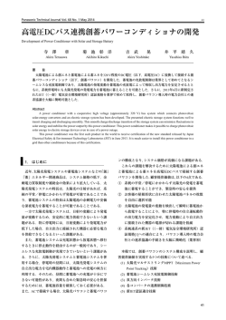
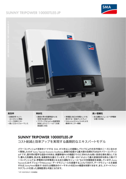
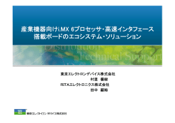
3 相 BLDC コントローラ IC SI-6633C アプリケーションノート 2015 年 1 月 Ver.1.4 MCD 事業部低圧モータグループ 本資料は、現在開発中の 3 相 BLDC モータコントローラの SI-6633C につい てまとめたものです。 本資料中には暫定的な内容が含まれていますので、取り扱いには注意をお 願いします。 本資料の内容は和英併記となっておりますが、和文優先とさせていただきま す。 なお、最新情報に関しては、弊社担当部門までお問合せ願います。 This application note is applied to SI-6633C, which is motor controller for 3-phase brushless motor. Care should be taken since the contents may be changed without any notice. This application note, which shows in Japanese and English, Japanese expression shall be given priority over English expression. About the latest information, please refer to our charge section. 〔目次〕 1. はじめに(General Description) ........................................................... 3 2. 主な機能(Features) ............................................................................ 4 3. 外形・参考ランド形状(Package information, recommended foot print)5 4. ブロック図&応用回路例(Block diagram and application circuit) ........ 6 4.1. Hall 素子入力 (Hall element input) ....................................6 4.2. Hall IC 入力 (Hall IC input) ................................................7 5. 端子表(Pin assignment) ...................................................................... 8 6. 絶対最大定格(Absolute maximum rating) ......................................... 10 7. 推奨動作範囲(Recommended operating range).................................. 10 8. 許容損失(Power dissipation) ............................................................ 11 9. 電気的特性(Electrical characteristics) ............................................... 12 10. 真理値表、タイミングチャート(Truth table, timing chart)........ 14 10.1. 10.2. 10.3. 10.4. 10.5. 10.6. 10.7. 10.8. 10.9. 励磁制御入力(ホール&Logic 入力) ..........................14 FL 出力(フラグ出力) ................................................15 FG 信号 .........................................................................16 Internal PWM 制御 ......................................................16 PWM 制御入力(PWM&Decay) ...............................17 同期整流強制停止(Fast Decay のみ) .......................17 OCP 制御 ......................................................................18 モータロック検出 .........................................................19 Enable&Brake 端子.....................................................20 サンケン電気株式会社 1 / 31 SI-6633C アプリケーションノート Ver. 1.4 11. 回路構成(個別回路)(Individual circuit structure) .................. 22 11.1. UVLO............................................................................22 11.2. TSD ...............................................................................22 11.3. OVP...............................................................................22 11.4. Charge Pump ...............................................................23 11.5. Gate Drive&OCP ........................................................23 11.6. Hall Amp ......................................................................24 11.7. FG Gen .........................................................................24 11.8. Commutation&Control Logic .....................................24 11.9. Internal PWM ..............................................................25 11.10. OSC ...............................................................................25 11.11. Lock Detect...................................................................26 12. 端子部内部回路(Pin diagram) ...................................................... 28 13. 動作波形(operational waveform).................................................. 29 14. 評価ボード回路図(Evaluation board schematic) ......................... 30 15. 評価ボードパターン図(Evaluation pattern layout)..................... 31 サンケン電気株式会社 2 / 31 SI-6633C アプリケーションノート Ver. 1.4 1. はじめに(General Description) 本 IC は 3 相ブラシレス DC モータ用プリドライバ IC です。このデバイスは幅広い N チャネルパワ ーMOSFET と組み合わせ可能で、30V までのモータ電源電圧に対応しています。120°間隔で配 置されたホール素子/ホール IC よって相切り替えを行います。 機能としては、突入電流を抑制する PWM 電流制御、過熱シャットダウン、同期整流などを備えて います。 同期整流機能では、ボディダイオードの代わりに低オン抵抗の MOSFET で整流を行い、回生時 の電力損失を低減できます。 本製品は enable, direction, brake 入力を備え、内部 PWM による電流制御が可能です。又、ロ ジック出力 FG により、モータの回転を検出することが可能です。 SI-6633C is a complete 3-phase brushless DC motor pre-driver. The device is capable of driving a wide range of N-channel power MOSFETs and can support motor supply voltages up to 30 V. Commutation logic is determined by three Hall-element / Hall IC inputs spaced at 120°. The device has PWM current control to limit rush current, thermal shut down and synchronous rectification. Internal synchronous rectification reduces power dissipation by turning on the appropriate MOSFETs during current decay, thus shorting the body diode with the low RDS(on) MOSFET. The device has enable, direction and brake input with internal PWM feature. Also, it can monitor the rotation of the motor by FG output. サンケン電気株式会社 3 / 31 SI-6633C アプリケーションノート Ver. 1.4 2. 主な機能(Features) 6 素子の N チャンネル MOSFET を駆動 Drive 6 N-channel MOFETs ホール入力対応 Hall element input 各種保護機能内蔵 Protections 過電圧保護 Over voltage protection 低電圧保護 Under voltage lock out 過電流保護(天絡、負荷ショート対応) Over current protection 過熱保護 Thermal shutdown ロック検知 Motor lock detection 貫通電流防止機能 Short-through Protection 異常発生時におけるアラーム出力機能 Alarm output pin (FLAG) is active when any protection is activated. 電力損失を低減する同期整流 Synchronous rectification with low power dissipation. PWM 電流制限 Fixed frequency PWM (Internal PWM) with peak current control. FG 出力 Motor speed output by hall input transition (FG). スタンバイモード Stand-by mode サンケン電気株式会社 4 / 31 SI-6633C アプリケーションノート Ver. 1.4 3. 外形・参考ランド形状(Package information, recommended foot print) Unit : mm サーマルパット付き QFN36Pin パッケージ QFN36 package with exposed pad 参考ランド形状(赤線部分) Recommended foot print (red line) サンケン電気株式会社 5 / 31 SI-6633C アプリケーションノート Ver. 1.4 4. ブロック図&応用回路例(Block diagram and application circuit) 4.1. Hall 素子入力 (Hall element input) VBB=10~30V VDD=3~5.5V V D D V B B HU+ Hall HU- UVLO CPL OVP HV+ Hall Amp Hall CPH Charge Pump Drv.Reg Int.Reg V C P HallU HV- GHU HallV HW+ Hall SU TSD HallW HW- GLU GHV Gate Drive & OCP FL SV GLV FG FG Gen Comm & Control Lock Detect Logic GHW OSC コ ン ト ロ ー ラ SW GLW Dir Enable Sen Brake ÷10 PWM Decay C L D C O S C G N D サンケン電気株式会社 R e f 6 / 31 SI-6633C アプリケーションノート Ver. 1.4 4.2. Hall IC 入力 (Hall IC input) VBB=10 30V VDD=3 5.5V V D D V B B HU+ HU- Hall IC UVLO HV+ CPL OVP Hall Amp HallU HVHall IC CPH Char ge Pu mp Dr v. Reg Int.Reg Hall IC V C P GHU HallV HW+ SU TSD HallW HW- GLU GHV Gate Drive & OCP FL SV GLV FG FG Gen Comm & Control Lock Detect Logic GHW OSC SW コント ローラ GLW Dir Enable Sen Brake ÷10 PWM Decay C L D C O S C G N D サンケン電気株式会社 R e f 7 / 31 SI-6633C アプリケーションノート Ver. 1.4 5. 端子表(Pin assignment) 番号 Pin No. 端子名 Pin Name 1 PWM 2 Dir 3 Decay 4 GND 5 CPL 6 CPH 7 VBB 8 VCP 9 GND 10 SW 11 GHW 12 GLW 13 SV 14 GHV 15 GLV 16 SU 17 GHU 18 GLU 19 GND 20 Sen 21 Ref 22 HW+ 23 HW- 端子機能 Functions PWM 信号入力端子 PWM input 電流方向切り替え端子 Direction input Decay 信号入力端子 Decay input グランド端子 Ground チャージポンプ汲み上げ用コンデンサ端子 Low Pumping for charge pump - Low チャージポンプ汲み上げ用コンデンサ端子 High Pumping for charge pump - High モータ電源入力端子 Motor power supply チャージポンプチャージアップ用コンデンサ端子 Reservoir pin for charge pump グランド端子 Ground 出力端子 OUTW Output for W phase ハイサイドゲート出力端子 W High side gate for W phase ローサイドゲート出力端子 W Low side gate for W phase 出力端子 OUTV Output for V phase ハイサイドゲート出力端子 V High side gate for V phase ローサイドゲート出力端子 V Low side gate for V phase 出力端子 OUTU Output for U phase ハイサイドゲート出力端子 U High side gate for U phase ローサイドゲート出力端子 U Low side gate for U phase グランド端子 Ground 電流検出端子 Current sensing input 内部 PWM 電流設定端子 Analog input for internal PWM current control ホール素子入力端子 HW+ Hall input W+ ホール素子入力端子 HWHall input W- サンケン電気株式会社 8 / 31 SI-6633C アプリケーションノート Ver. 1.4 番号 Pin No. 端子名 Pin Name 24 HV+ 25 HV- 26 HU+ 27 HU- 28 GND 29 CLD 30 COSC 31 VDD 32 FG 33 FL 34 Brake 35 Enable 36 GND 端子機能 Functions ホール素子入力端子 HV+ Hall input V+ ホール素子入力端子 HVHall input Vホール素子入力端子 HU+ Hall input U+ ホール素子入力端子 HUHall input Uグランド端子 Ground ロック検知時間設定端子 Setting for lock detection timer スイッチング周波数設定端子 Setting for switching frequency ロジック電源端子 Logic power supply FG 出力端子 Output for FG signal 異常検知出力端子 Output for protection detected ブレーキ入力端子 Brake input ロックカウンターリセット信号&Enable 信号入力端子 Reset for lock counter and Enable input Break FL FG VDD COSC 35 34 33 32 31 30 GND Enable 36 CLD GND グランド端子 Ground 2 9 2 8 PWM 1 27 HU- Dir 2 26 20 HU+ Decay 3 25 HV- GND 4 24 HV+ CPL 5 23 HW- CPH 6 22 HW+ VBB 7 21 REF VCP 8 20 SEN GND 9 19 GND 12 13 14 15 16 GHW GLW SV GHV GLV SU 1 7 1 8 GLU 11 GHU 10 SW SI-6633C サンケン電気株式会社 9 / 31 SI-6633C アプリケーションノート Ver. 1.4 6. 絶対最大定格(Absolute maximum rating) 項目 Items 電源電圧 Power supply 出力電圧 Output voltage ロジック入力電圧 Logic input voltage ホール入力電圧 Hall input voltage Ref 入力電圧 Reference input voltage 検出電圧 Sense voltage 最高ジャンクション温度 Junction temperature 保存温度 Storage temperature 動作周囲温度 Ambient temperature パッケージ熱抵抗 Thermal resistance 記号 Symbol 規格値 Spec 単位 Units VBB -0.3~38 V VOUT -1~38 V VIN(Logic) -0.3~6 V VHALL -0.3~6 V VRef -0.3~6 V VSENSE ±0.5 V TJ(max) 150 ℃ Tstg -40~150 ℃ TA -20~85 ℃ 43 ℃/W RθJA 条件 Condition 弊社評価基板使用時(2 層基板;60mm×77mm) SK evaluation board(2 layer PCB; 60mm*77mm) (※)出力電流はデューティサイクル、周囲温度、放熱状態によって制限を受けることがあります。いかな る使用条件下においても、決して指定された定格電流および最大接合部温度(Tj=150℃)を超え ないようにしてください。 Output current rating may be limited by duty cycle, ambient temperature, and heat sinking. Under any set of conditions, do not exceed the specified junction temperature (Tj). 7. 推奨動作範囲(Recommended operating range) 項目 Item 電源電圧 Power supply コントロール電源電圧 Logic power supply ロジック入力電圧 Logic input voltage Ref 入力電圧 Reference input voltage ホール入力電圧 Hall input voltage 検出電圧 Sense voltage パッケージ温度 Package temperature 動作周囲温度 Ambient temperature 記号 Symbol 規格値 Spec 単位 Unit VBB 10~30 V VDD 3~5.5 V VIN(Logic) 0~5.5 V VRef 0.5~5.5 V VHALL 0.2~4 V VSENSE ±0.5 V TC 105 ℃ TA -20~85 ℃ 備考 Remarks 0.5V 以下では、電流制御精度が大幅に低下します。 Current accuracy is going down under 0.5V. サンケン電気株式会社 10 / 31 SI-6633C アプリケーションノート Ver. 1.4 8. 許容損失(Power dissipation) パッケージ使用時の減定格(Power dissipation) パッケージ許容損失 PD[W] 4 3.5 3 2.5 2 43℃/W 1.5 1 0.5 0 -20 0 20 周囲温度 40 60 80 100 Ta [℃] 弊社評価基板使用時(2 層基板;60mm×77mm) SK evaluation board(2 layer PCB; 60mm*77mm) サンケン電気株式会社 11 / 31 SI-6633C アプリケーションノート Ver. 1.4 9. 電気的特性(Electrical characteristics) 特記なき場合、TA=+25℃、VBB=24V、VDD=5V (Ta=25°C,VBB=24V,VDD=5V,Unless Otherwise Noted.) 特性項目 Item 定格 Spec 記号 Symbol MIN TYP MAX 単位 Unit VBB 10 - VBBOV V - 10 20 mA 50 - 200 μA 3 - 5.5 V - 0.5 3 mA 100 180 500 μA 試験条件 Condition Output Drivers VBB 電圧範囲 Power supply voltage range 主電源電流 Power supply current IBB 動作時 Motor operation 動作状態(出力 OFF 時) Motor operation(Output disable) スタンバイモード Stand-by mode Control Logic VDD 電圧範囲 Logic supply voltage range VDD 端子電流 Logic supply current VDD IDD 動作時 Motor operation 動作状態(出力 OFF 時) Motor operation(Output disable) スタンバイモード Stand-by mode Logic 入力電圧 Logic input voltage VIN(0) - - VDD×0.25 V VIN(1) VDD×0.75 - - V Logic 入力電流 Logic input current IIN(0) -1 - 1 μA VIN(0) , VIN=0V IIN(1) -1 - 1 μA VIN(1) , VIN=5V tLOGIC 0.3 0.5 0.95 μs fin=50kHz、Duty=50% fOSC 19 25 32 KHz VGS(H) 6 - 9 V Vbb に対して, IGATE=2mA For VBB. IGATE=2mA VGS(L) 6 - 9 V IGATE=2mA IGATE 20 30 60 mA tdead - 1000 - ns Iref -5 -0.1 1 μA VRef 0.5 - 5.5 V ISen -5 -0.1 1 μA VSen=0~1V VSen VREF×0.095 VREF×0.1 VREF×0.12 V VRef=1~5V tLPFSen 1 2 4 μs 設計保証 Guaranteed by design 入力端子フィルタ Logic input filter COSC 端子発振周波数 COSC oscillation frequency COSC=330pF Gate Drive ハイサイド出力電圧 High side output voltage ローサイド出力電圧 Low side output voltage ドライブ電流 Drive current デッドタイム Deadtime GH=GL=4V、VCP=VBB+TBD Internal PWM Ref 端子入力電流 Reference input current Ref 端子入力電圧範囲 Reference input voltage range Sen 端子入力電流 Sense input current 検出電圧 Sense voltage 電流検出フィルタ時間 Current sense filter time ※1:Typ データは設計情報として使用して下さい。 Typ data is for reference only. ※2:表中の負電流は製品端子から流れ出る電流を示しております。 Negative current is defined as coming out of the specified pin. サンケン電気株式会社 12 / 31 SI-6633C アプリケーションノート Ver. 1.4 特記なき場合、TA=+25℃、VBB=24V、VDD=5V (Ta=25°C,VBB=24V,VDD=5V,Unless Otherwise Noted.) 特性項目 Item 定格 Spec 記号 Symbol MIN TYP MAX 単位 Unit 試験条件 Condition VFI(ON) 0.2 0.4 0.7 V IFI(ON) 5 7.5 15 mA VFI=2V IFI(OFF) 0 - 50 μA VFG=5.5V VOCP 1.4 1.5 1.65 V LowSideMOSFET 検出 (OUT-GND 間) tFLTOCP 0.75 1.5 3 μs 設計保証 Guaranteed by design NOCP_OFF 256 256 256 VBBOV 33 35 37 V VBBOVhys 1.25 2 3.5 V fLD 100 128 164 Hz CLD=0.1μF NLD 256 256 256 TJTSD 151 170 185 ℃ TJTSDhys 10 15 20 ℃ 温度上昇時、設計保証 Temperature rising, Guaranteed by design. VDDUV 2.65 2.8 2.95 V VDDUVhys 0.1 0.15 0.25 V VBBUV - 9 9.9 V VBBUVhys - 0.3 - V VFG(sat) 0.2 0.4 0.7 V IFG=2mA IFGlkg 0 - 50 μA VFG=5.5V IHALL -5 -0.1 1 μA VIN=0.2~4V VCMR 0.2 - 4 V VHALL 60 - - mVp-p VHYS 25 40 VHALL mV tpulse 1 2 4 μs Protection FL 出力飽和電圧 FL output saturation voltage FL 出力端子オン電流 FL output On current FL 出力リーク電流 FL output leak current 過電流検出電圧 OCP detection voltage 過電流検出フィルタ時間 OCP filter time OCP 出力 OFF タイマーカウント OCP output off timer count VBB 過電圧保護閾値電圧 VBB OVP threshold voltage VBB 過電圧保護ヒステリシス VBB OVP hysteresis CLD 端子発振周波数 CLD oscillation frequency ロック検出タイマーカウント Lock detection timer count 過熱保護動作温度 TSD threshold temperature 過熱保護ヒステリシス TSD hysteresis VDD 低電圧保護解除電圧 VDD UVLO threshold voltage VDD 低電圧保護ヒステリシス VDD UVLO hysteresis VBB 低電圧保護解除電圧 VBB UVLO threshold voltage VBB 低電圧保護ヒステリシス VBB UVLO hysteresis IFG=2mA VDD 電圧上昇時 VDD rising VBB 電圧上昇時 VBB rising FG FG 出力飽和電圧 FG output saturation voltage FG 出力リーク電流 FG output leak current Hall Logic ホール入力電流 Hall input current コモンモード入力電圧範囲 Common mode input voltage range AC 入力電圧範囲 AC input voltage range ヒステリシス Hysteresis パルス除去フィルタ Pulse reject filter 設計保証 Guaranteed by design ※1:Typ データは設計情報として使用して下さい。 Typ data is for reference only. ※2:表中の負電流は製品端子から流れ出る電流を示しております。 Negative current is defined as coming out of the specified pin. サンケン電気株式会社 13 / 31 SI-6633C アプリケーションノート Ver. 1.4 10. 真理値表、タイミングチャート(Truth table, timing chart) 10.1. 励磁制御入力(ホール&Logic 入力) 10.1 Excitation control input (Hall and Logic input) 表 10-1 Hall 入力&各制御入力 Table 10-1 Hall and Logic input Input 状態名 ※1 F1 F2 F3 F4 F5 F6 Error Error brake disable※2 StandBy HallU + + + + X X X ※1 HallV + + + + X X X HallW + + + + X X X ※1 Enable L L L L L L L L L H H Brake H H H H H H H H L H L OUTU H H Z L L Z Z Z L Z Z Output status DIR=H OUTV OUTW OUTU L Z L Z L L H L Z H Z H Z H H L H Z Z Z Z Z Z Z L L L Z Z Z Z Z Z DIR=L OUTV OUTW H Z Z H L H L Z Z L H L Z Z Z Z L L Z Z Z Z X:don‟t care Z:High Impedance ※1 HallU、HallV、HallW:‟+‟=H+>H- 、‟-„ =H+<H※2 Disable となるには条件があります。 There are conditions for disable HallU、HallV、HallW は HU+、HU-、HV+、HV-、HW+、HW-から生成される、内部 ロジック信号名となります。 HallU, HallV and HallW are internal logic signal made from HU+, HU-, HV+, HV-, HW+ and HW-. Disable となる条件については、図 を参照願います。 Refer to Fig 10-9 for condition of “disable” サンケン電気株式会社 14 / 31 SI-6633C アプリケーションノート Ver. 1.4 10.2. FL 出力(フラグ出力) 10.2 Flag Output 表 10-2 FL 出力 Table 10-2 Flag output FL 出力 状態(Status) Hi-Z 動作状態(Operation) L 異常検知 低電圧保護(UVLO) Abnormal Under voltage lock out 過熱検知(TSD) Thermal shutdown 過電圧検知(OVP) Over voltage protection 過電流検知&出力 OFF 期間(OCP) Over current protection and output off time ・電源電圧(VBB、VDD)が低い状態では内部回路の動作が不完全となって正しい診断結果 を出力しない場合がありますので、注意願います。 Please take care for FLAG output due to the internal circuit may not be fixed with supply voltage (VBB and VDD) being low. サンケン電気株式会社 15 / 31 SI-6633C アプリケーションノート Ver. 1.4 10.3. FG 信号 10.3 FG signal 図 10-3 FG タイミングチャート Fig 10-3 FG timing chart DIR HallU HallV HallW FG ・HalU、HallV、HallW に関しては、「10.1 励磁制御入力(ホール&Logic 入力)」を参照願 います。 Refer to “10.1 Hall and Logic input” on HalU, HallV and HallW. ・FG はホール入力によって励磁相が切り替わる毎に論理が反転する、トグル動作となります。 FG is toggled by each phase changed. 10.4. Internal PWM 制御 10.4 Internal PWM control 図 10-4 内部 PWM タイミングチャート Fig 10-4 Internal PWM control timing chart tLPFSen tLPFSen COSC 0.1×REF Sen 拡大 フィルタにより無感 Sen OUTx 励磁動作ON OUTx 同期整流制御ON ・本制御を使用しない場合は、Sen は GND、REF は VDD に接続してください。 Connect Sen pin to GND and Ref pin to VDD if not using this function. サンケン電気株式会社 16 / 31 SI-6633C アプリケーションノート Ver. 1.4 10.5. PWM 制御入力(PWM&Decay) 10.5 PWM control (PWM and Decay) 図 10-5 PWM タイミングチャート Fig 10-5 PWM control timing chart Decay OFF PWM ON A相 H/S L/S H/S L/S B相 L/S H/S L/S H/S H/S L/S H/S L/S 出力オン 状態 L/S ・Brake 時は、PWM 端子、Decay 端子の入力信号は無視されます。 PWM and Decay signal is ignored in Brake mode. ・PWM 制御入力を使用しない場合は、端子を’L’としてださい。 Connect PWM pin to “L” if not using this function. 10.6. 同期整流強制停止(Fast Decay のみ) 10.6 PWM operation in Fast Decay (Decay=”H”) 図 10-6 同期整流タイミングチャート Fig 10-6 Synchronous Rectification timing chart PWMチョッピング ON OFF ON OFF ON OFF ON OFF COSC 1 2 3 1 2 3 1 2 3 4 5 6 7 1 A相 H/S L/S H/S L/S H/S L/S OFF H/S L/S B相 L/S H/S L/S H/S L/S H/S OFF L/S H/S 2 出力オン 状態 ・PWM チョッピング OFF 期間が一定時間(COSC の約 7 周期)継続した場合には同期整流 動作を停止させます。 If the device keeps OFF (PWM=”H”) for 7 cycles of COSC, SR function is disabled. ・Brake 時はこの機能は動作しません。 This function is not applied to Brake mode. サンケン電気株式会社 17 / 31 SI-6633C アプリケーションノート Ver. 1.4 10.7. OCP 制御 10.7 OCP control 図 10-7 OCP タイミングチャート Fig 10-7 OCP timing chart 1.5V OUTx 出力OFF 1 2 3 出力OFF 254 255 256 1 2 COSC FL 出力’Z’ 出力’L’ (※図中の数値は typ 値) The value is typical in the timing chart ・過電流検知後、一定時間(COSC の 256 周期)出力 OFF となり、その後自動復帰します。 After OCP event is detected, outputs are disabled for 256 cycles of COSC. After the disable time finished, the device automatically re-starts again. ・出力 OFF 時間のタイマーカウントと FL 出力解除は COSC のトップのタイミングで行われま す。 The trigger for off timer count and release of FL output is at the top of COSC oscillation waveform. ・OFF 期間の解除は COSC のボトムのタイミングとなります。 The trigger for release of off timer count is at the bottom of COSC oscillation. ・出力 OFF 時間のタイマーカウントは出力 Disable としてもリセットされません。 The timer count for output off is not reset with output disable. サンケン電気株式会社 18 / 31 SI-6633C アプリケーションノート Ver. 1.4 10.8. モータロック検出 10.8 Motor lock detection 図 10-8 ロック検知タイミングチャート Fig 10-8 Motor lock detection timing chart RST CLD 1 2 1 2 255 256 1 2 出力’Z’ FLAG 出力’L’ COSC 出力 ON OFF ON ・ロック検出は、回転状態(Enable 端子=‟L‟、Brake 端子=‟H‟)時のみ動作をします。 Lock detection is enabled only in motor operating (Enable=”L”, Brake=”H”). ・CLD の発振周期で約 256 周期、ロック検出を解除する信号(RST)の発生がなかった場合、 モータロックと判断して出力をシャットダウンします。 The device recognizes lock condition if RST signal (H) is not for about 256 cycles of CLD. ・RST 信号は、図 10-8 や「11.回路構成(個別回路)」の「11.11 Lock Detect」を参照願いま す。 Please refer to Fig 10-8 above and 11.11 Lock detect. サンケン電気株式会社 19 / 31 SI-6633C アプリケーションノート Ver. 1.4 10.9. Enable&Brake 端子 10.9 Enable and Brake 図 10-9 Enable と Brake のタイミングチャート Fig 10-9 Enable and Brake timing chart Enable Brake COSC 1 LDカウンター 動作 動作状態 2 リセット 回転 1 動作 リセット ブレーキ 2 動作 3 4 1 リセット 回転 動作 Disable 2 リセット 回転 スタンバイ Disable ・Enable 端子には優先動作の順に、次の 3 つの機能があります。 Below is the function of Enable pin with higher priority. ① タンバイ制御(Brake 端子との組合せ) ① Stand-by control (combination of Brake=L and Enable=H) Brake=‟L‟、Enable=‟H‟の組合せとなることでスタンバイへ移行し、この組合せから外れ るとスタンバイから復帰します。 Combination of Brake=”L” and Enable=”H” make the device get stand-by mode. To get out of stand-by mode, it is needed to remove this combination. なおスタンバイ時はチャージポンプ回路や内部 Reg が停止します。そのためスタンバイ 解除となってから実際に動作を開始するまでには時間がかかります。 また FL 端子は、スタンバイ時は‟H‟となり、解除後は内部状態に従って出力されます。 In stand-by mode, charge pump circuit and internal regulator is disabled. It takes some time for the device to resume the operation after the device released stand-by mode. For FL pin, output is H in stand-by mode and it is according to the device condition after stand-by mode is released. ②ロックカウンターリセット ②Reset for lock counter Enable=‟H‟の期間中はロックカウンターがリセット状態となります。 The device is in reset of lock counter for Enable=”H” サンケン電気株式会社 20 / 31 SI-6633C アプリケーションノート Ver. 1.4 ③出力 Enable/Disable 動作 ③Enable/Disable control of output 出力 Disable となるのは、Enable 端子が‟L‟→‟H‟となってから COSC の発振回数(ボト ムのタイミングでカウント)が 4 回目の時となります。 出力 Enable となるのは、Enable 端子が‟H‟→‟L‟となった次のオントリガー(COSC のボト ム)のタイミングとなります。 The device counts the oscillation of COSC after Enable pin changing from “L” to “H”. After counting 4 cycles of COSC, the device gets in “disable” mode. The device recovers to “enable” mode with switching Enable pin from “H” to “L” immediately. サンケン電気株式会社 21 / 31 SI-6633C アプリケーションノート Ver. 1.4 11. 回路構成(個別回路)(Individual circuit structure) 11.1. UVLO 11.1 Under Voltage Lock Out 電源状態が正常動作可能な電圧値以下となった時に保護をする回路になります。 低電圧保護は VDD、IC の内部電源とチャージポンプで昇圧した電圧をモニターしていま す。 モニターしている電圧が設定より低い場合は、出力をシャットダウンします。 This block is for protection to avoid the device damaged. The block makes all outputs shutdown if the device is below voltage where the device can‟t control internal circuit. The block monitors the voltages on VDD, internal regulator and charge pump. 11.2. TSD 11.2 Thermal Shut Down 制御 IC のジャンクション温度をモニターし、製品の過熱を防ぐ保護回路になります。 過熱保護は、IC の温度が 170℃付近まで上昇すると出力をシャットダウンします。 その後、制御 IC の温度が 15℃程度低下すると出力のシャットダウンは解除されます。 なお、この機能は定常的に動作させて使用するものではありませんので、この機能が動作しな いよう熱設計を行ったうえで、使用してください。 TSD block monitors junction temperature to avoid the overheating of the device. The block makes all outputs shutdown with junction temperature being over 170C. The TSD is released with temperature falling by 15C. TSD function is not for use in normal operation. Care should be taken not to use this function from the thermal design point of view. 11.3. OVP 11.3 Over Voltage Protection 製品に印加される主電源電圧(VBB)が絶対最大定格付近まで高くなると、出力をシャットダ ウンして製品が最も過電圧に対して耐量の得られる過電圧保護(OVP)状態に移行します。 本製品の OVP は、約 35V で動作します。 なお、これ以上の電圧を印加してもモータを動作させることは出来ません。 This block monitors VBB voltage and make output shut down with VBB being near to the absolute max rating to keep the device endure from the over voltage condition. OVP is active with VBB being 35V (typ). The device can‟t be operated under OVP condition. サンケン電気株式会社 22 / 31 SI-6633C アプリケーションノート Ver. 1.4 11.4. Charge Pump 11.4 Charge Pump ハイサイド(上アーム)側の Nch MOSFET を駆動するための昇圧電源になります。 通常動作時には、CP 端子は主電源(VBB)より 7V 程度高い電位状態になります。 昇圧動作にはコンデンサが必要となりますが、下記点に注意願います。 This block is boost supply to drive high-side N-channel MOSFET. The voltage of CP pin becomes higher than that of VBB pin by 7V. You should put capacitors at CP-VBB and CPH-CPL, and should also take care below. ☆CP-VBB 間 ☆CP-VBB 通常時は CP 端子が VBB 端子より高電位となりますが、チャージポンプが起動し CP 端 子の電圧が上昇するまでの間、CP 端子電圧が VBB 端子より 1V 程度下がることがありま す。 The voltage of CP pin is higher than that of VBB pin. However, in start-up conditions, the voltage of CP pin may be lower than that of VBB by 1V. ☆CPH-CPL 間 ☆CPH-CPL VBB と同等の電圧が加わりますので、耐圧には注意して下さい。 You should take care of the breakdown voltage for the capacitor since the voltage on the capacitor is same as that of VBB. 11.5. Gate Drive&OCP 11.5 Gate Drive and OCP Gate Drive は Control Logic の信号を受けて出力 Nch MOS FET を駆動するプリドライバ の回路になります。 このブロックにてハイサイド(上アーム)とローサイド(下アーム)を同時にスイッチング動作させ る際に留意しなければならない貫通電流を防ぐデットタイムも設定されています。 また本製品には、過電流保護回路(OCP)も搭載されています。 この過電流保護回路は、ローサイド MOS FET が ON のときのドレイン電圧(OUT 端子~ GND 間電圧)をモニターしており、その閾値電圧は 1.5V(typ)になります。 Gate Drive circuit is pre-driver which drives external output MOSFET according to the signal from control logic. The block also has the dead time function which is to avoid short-through condition between high side and low side. In addition, the device has OCP (Over Current Protection) function. This feature is achieved by monitoring drain voltage (the voltage between OUT and GND) with low side MOSFET being active. The threshold voltage is 1.5V (typ) サンケン電気株式会社 23 / 31 SI-6633C アプリケーションノート Ver. 1.4 11.6. Hall Amp 11.6 Hall Amplifier 標準的なホール素子を接続します。 The device should be connected with hall element as a typical application. 11.7. FG Gen 11.7 FG generator Hall Amp からの信号を受けて、モータ回転パルスを FG 端子から出力します。 同時にロック検出のリセット用の信号を生成します。 This block makes rotation pulse from FG pin through hall amp and commutation logic. It also makes reset signal for lock detection. 11.8. Commutation&Control Logic 11.8 Commutation and Control logic Hall Amp から得た位置信号、PWM 制御信号、保護回路系からの出力オフ信号などから、 Gate Drive へ送るパワーMOSFET の ON/OFF 信号を合成します。 This block makes ON/OFF signal of external MOSFET to gate drive block. The signal is made from position signal from Hall amp, PWM control signal and the signal from protection circuit. サンケン電気株式会社 24 / 31 SI-6633C アプリケーションノート Ver. 1.4 11.9. Internal PWM 11.9 Internal PWM 外部から入力する電流基準信号(アナログ電圧)に合わせ、モータコイルに流れるピーク電流 を制御します。 The block controls peak current of motor winding according to the external analog voltage. The block also has noise filter for rising edge of chopping ON. なおチョッピングオン時に発生するノイズに対するフィルタを搭載しています。 PWM 動作としては、OSC からのトリガ信号でチョッピングオンとなり、コイル電流が設定した電 流(ピーク電流値 IOpeak)となると、チョッピングオフとなります。 スイッチング周波数は、OSC の項にある fOSC で一定となります。 As a operation of internal PWM function, it is chopping ON with trigger signal from PWM OSC (Bottom point of CPWM oscillation waveform) and it is chopping OFF with the motor current hit the peak current setting (IOpeak). IOpeak の設定値は、下記の計算式で算出できます。 Below is the formula of IOpeak [A] I Opeak 0.1 V REF RS ただし、VREF:REF 端子電圧 RS:電流検出抵抗値 VREF: analog voltage on REF pin / RS:sense resistance 本機能を使用しない場合は、Sen 端子は GND、REF 端子は VDD と接続することで、内部 PWM 制御は機能しなくなります。 You can neglect the function with Sen pin tie to GND and REF pin tie to VDD. 11.10. OSC 11.10 PWM Oscillation 製品の多くの動作タイミングや時間を決めています。 そのため、必ずコンデンサを接続して発振動作させる必要があります。 This block sets the PWM operation frequency and basic signal regarding operation timing in the device. The capacitor is needed on CPWM pin to oscillate. 発振周波数 fOSC は OSC 端子に接続するコンデンサで決まり、下記の計算式で算出されま す。 Oscillation frequency (fPWM) is set to the capacitance on CPWM pin. Below is the formula. f OSC kHz 8.3 C OSC nF サンケン電気株式会社 25 / 31 SI-6633C アプリケーションノート Ver. 1.4 11.11. Lock Detect 11.11 Lock Detect モータロック状態を検知する機能となります。 CLD 端子のコンデンサ(CLD)と内部分周比で決まる一定時間ホール入力信号が変化しない 状態が発生すると、モータロック状態と判断しモータへの通電をシャットダウンします。同時に FL 端子が Low となりロック状態であることを伝えます。 This block is motor lock detection. If hall input signal is not changed for the time of tLD, which is made by the capacitor on CLD pin and internal divider, the device recognizes “lock condition” and also makes all outputs shut down. In addition, FL pin goes low to indicate lock condition. CLD 端子容量とロック検出時間 tLD の関係は、下記の計算式で算出されます。 The formula regarding tLD and capacitance on CLD pin is below. t LD 20 C LD F 内部カウンタのリセットやロック検知後のシャットダウン状態から復帰させるためには、以下の 何れかの信号を入力する必要があります。 To reset the internal counter and to resume from all outputs off after lock detection, any of below condition is needed. ☆ホール入力を変化させる。 Change the hall signal. ☆Brake 端子の論理をブレーキ(‟L‟)に設定する。 Brake pin tie to L (Brake mode) ☆Enable 端子の論理をディセーブル(‟H‟) に設定する。 Enable pin tie to H (Disable mode) ☆Dir 端子の論理を切り替える。 Change the logic signal of Dir pin. ☆電源の再投入を行う。 Power up cycle on VBB. ロック検知でモータ停止後、何らかの要因でモータが回転してホール入力が切替わると、カウ ンタはリセットされロック検知状態から復帰します。 Lock counter is reset with every cycle for hall transition. After motor stopped with lock condition, if the motor is rotated with some external force and hall signal is changed, the device reset lock condition and operate again. モータを励磁している状態でロック検知を強制的に回避しようとする場合は、ロック検出時間よ りも短い周期で、Dir 端子の論理を切り替えるか、または Enable 端子に Disable 状態とならな い狭い幅(COSC の約 4 周期未満)の‟H‟のパルスを入力してください。 If you intentionally want to avoid lock condition with motor operated, you should change the signal on Dir pin with shorter term than tLD or should put H signal on Enable pin for short time (shorter than 4 cycles of CPWM). サンケン電気株式会社 26 / 31 SI-6633C アプリケーションノート Ver. 1.4 なお VDD の低電圧保護以外の保護機能(Reg と CP-VBB 間の UVLO、TSD、OVP、OCP) の動作ではロックカウンターはリセットされずタイマーカウントを継続します。これら保護機能によ ってモータが停止した場合にロックであると判断し、本保護機能によるモータ停止状態となる場 合があります。 Except for VDD UVLO, lock detection function is active even if other protection (Internal Reg and charge pump UVLO, TSD, OVP and OCP) is asserted. In this condition, the motor may be stopped with lock condition even if the abnormal mode is released. To make the motor operate again from this condition, you should release lock condition after abnormal mode is released. サンケン電気株式会社 27 / 31 SI-6633C アプリケーションノート Ver. 1.4 12. 端子部内部回路(Pin diagram) サンケン電気株式会社 28 / 31 SI-6633C アプリケーションノート Ver. 1.4 13. 動作波形(operational waveform) VBB=24V,DIR=H,Slow decay OUTU OUTV OUTW IOUTU サンケン電気株式会社 29 / 31 SI-6633C アプリケーションノート Ver. 1.4 14. 評価ボード回路図(Evaluation board schematic) サンケン電気株式会社 30 / 31 SI-6633C アプリケーションノート Ver. 1.4 15. 評価ボードパターン図(Evaluation pattern layout) ※PDF 化の影響で一部(QFN ランド部パターン等)実際と異なる箇所がございますがご了承くださ い。 The difference layout may be(Especially foot pattern around QFN) with printing in PDF. サンケン電気株式会社 31 / 31
© Copyright 2026 Paperzz