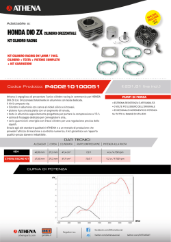
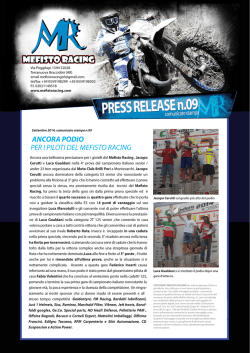
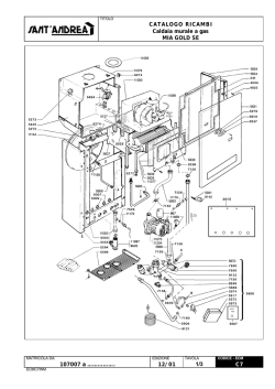
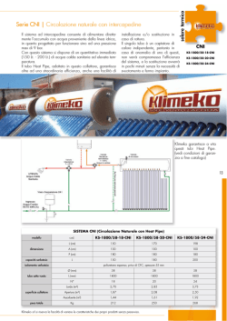
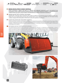
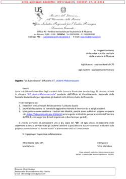
Modelli di riferimento: / Reference Ducati Motorcycles:
ISTR - 580 ED./ED. 00
Diavel MY’15
Kit scarico completo racing / Racing complete exhaust system kit - 96480341A - Black 96480641A
WARNING: This exhaust kit is for racing use (i.e., closedcourse competition) only. After mounting this exhaust kit,
the vehicle cannot be used on public roads. Owner is
responsible for compliance with all laws concerning racing
use and competition vehicles.
ATTENZIONE: Il presente kit di scarico è per utilizzo
esclusivo su pista (esempio: gare sportive su circuiti).
Dopo il montaggio del kit, il motoveicolo non può circolare
su strade pubbliche. Il proprietario si impegna ad attenersi
alle leggi e regolamenti vigenti sull'utilizzo in pista e sui
motoveicoli da competizione.
1
2
3
4
5
6
7
8
9
10
11
12
13
Tubo scarico verticale
Tubo scarico orizzontale
Tubo scarico centrale
Silenziatore racing
Paracalore in carbonio
Clip (q.tà 2)
Vite TBEI M5x12 (q.tà 2)
Rosetta aramidica (q.tà 4)
Distanziale (q.tà 2)
Molla (q.tà 4)
DDS Map key DP2
Staffa silenziatore
Vite TEF M8x16 (q.tà 2)
10
8
9
6
5
7
1
9
8
13
6
2
10
12
10
13
3
11
4
1
2
3
4
5
6
7
8
9
10
11
12
13
Vertical exhaust pipe
Horizontal exhaust pipe
Central exhaust pipe
Racing silencer
Carbon heat guard
Clip (q.ty 2)
TBEI screw M5x12 (q.ty 2)
Aramid washer (q.ty 4)
Spacer (q.ty 2)
Spring (q.ty 4)
DDS Map key DP2
Silencer bracket
TEF screw M8x16 (q.ty 2)
I particolari evidenziati in grigio e riferimento numerico (Es. 2 ) rappresentano l’accessorio da
installare e gli eventuali componenti di montaggio forniti a kit. I particolari con riferimento
alfabetico (Es. A ) rappresentano i componenti originali presenti sul motoveicolo.
Per una lettura rapida e razionale sono stati impiegati simboli che evidenziano situazioni di
massima attenzione, consigli pratici o semplici informazioni.
Tutte le indicazioni destro o sinistro si riferiscono al senso di marcia del motociclo.
Parts highlighted in grey and with a numeric reference (Example 2 ) are the accessory to be
installed and any assembly components supplied with the kit. Parts with an alphabetic reference
(Example A ) are the original components fitted on the vehicle.
For easy and rational reading, this document uses graphic symbols for
highlighting situations in which maximum care is required, practical advice or simple information.
Any right- or left-hand indication refers to the vehicle direction of travel.
Attenzione / Warning
La non osservanza delle istruzioni riportate può creare una situazione di pericolo e causare
gravi lesioni personali e anche la morte. / Failure to follow these instructions might give raise to
a dangerous situation and provoke severe personal injuries or even death.
Importante / Caution
Indica la possibilità di arrecare danno al veicolo e/o ai suoi componenti se le istruzioni
riportate non vengono eseguite. / Failure to follow these instructions might cause damages to the
vehicle and/or its components.
Note / Note
Fornisce utili informazioni sull'operazione in corso. / Useful information on the procedure
being described.
Cod. ISTR - 580 ED./ED. 00
Pag. - Page 1/5
Note
Prima di iniziare l’operazione, leggere
attentamente le avvertenze riportate nella
prima pagina.
Smontaggio componenti
originali
Note
Read the instructions on the first
page carefully before proceeding.
Removing the original
components
Warning
Attenzione
Le operazioni di seguito riportate
devono essere eseguite da un tecnico
specializzato o da un’officina autorizzata
DUCATI.
J
H
Attenzione
Le operazioni di seguito riportate se
non eseguite a regola d’arte possono
causare gravi rotture al motore e
pregiudicare la sicurezza del pilota.
G
Note
I
K
Documentazione necessaria per
eseguire il montaggio del Kit é il: MANUALE
OFFICINA, relativo al modello di moto in
vostro possesso.
Smontaggio impianto scarico
Procedere allo smontaggio dell’impianto di
scarico come riportato al capitolo
“Smontaggio impianto di scarico”,
procedendo come descritto di seguito:
- Smontare il gruppo silenziatore originale
(A) recuperando la vite (B), la boccola (C),
i gommini (D) e il dado (E).
- Smontare il gruppo scarico centrale (F).
- Smontare il gruppo scarico verticale (G).
- Smontare il gruppo scarico orizzontale (H)
recuperando la sonda lambda (I), la
guarnizione (J) e i dadi (K).
F
E
Have the kit installed by a trained
technician or at a DUCATI Authorized
Workshop.
Warning
Incorrect installation of this kit may
lead to severe engine damage and put the
rider’s safety at risk.
Note
Some of the operations required to
install this kit are described in the
WORKSHOP MANUAL for your motorcycle
model.
Removing the exhaust system
Remove the exhaust system as explained
under “Removing the exhaust system”,
following this sequence:
- Remove the original silencer unit (A)
recovering the screw (B), the bushing (C),
the rubber blocks (D) and the nut (E).
- Remove the central exhaust pipe unit (F).
- Remove the vertical exhaust unit (G).
- Remove the horizontal exhaust unit (H),
lambda sensor (I), seal (J) and nuts (K).
A
D
B
C
Pag. - Page 2/5
Cod. ISTR - 580 ED./ED. 00
Montaggio componenti kit
Importante
Verificare, prima del montaggio, che
tutti i componenti risultino puliti e in
perfetto stato. Adottare tutte le precauzioni
necessarie per evitare di danneggiare le
zone nelle quali si opera.
L1
L
Durante il montaggio di componenti
in carbonio porre particolare attenzione al
serraggio delle viti di fissaggio. Serrare gli
elementi di fissaggio senza forzare
eccessivamente per evitare che il carbonio
si danneggi.
Montaggio scarico completo
Note
È consigliato sostituire le guarnizioni
di scarico montate sulle teste con
guarnizioni nuove.
L
M
Facendo riferimento al capitolo
“Smontaggio impianto di scarico”,
smontare il gruppo motorino valvola scarico
(L) svitando le viti (L1).
Aiutandosi con un paio di pinze commerciali
svincolare il cavo (M) dalla carrucola del
motorino (L) e rimuovere il cavo dalla moto.
Rimontare il gruppo motorino (L) avvitando
e serrando le viti (L1).
N
Posizionare la guarnizione (N) e il tubo
scarico orizzontale (1) sui prigionieri della
testa orizzontale avvitando i dadi (K)
originali.
1
1
Avvitare e serrare la sonda lambda originale
(I) sul tubo scarico orizzontale (1)
assicurandosi che sia ancora collegata al
cablaggio principale.
Montare le clip (6) sul tubo (1). Inserire le
rondelle (8) sulle viti (7) e inserirle nel
paracalore (5); Dal lato posteriore del
paracalore inserire sul filetto delle viti i
distanziali (9) muniti di rondelle (8).
Posizionare il gruppo paracalore (5) sul tubo
(1) avvitando e serrando le viti (7) sulle clip
(6).
I
8
Caution
Check that all components are clean
and in perfect condition before installation.
Take all necessary measures to avoid
damaging the nearby surfaces.
Warning
Attenzione
K
Kit installation
When fitting carbon parts, take
special care when tightening fastening
screws. Tighten fasteners without forcing
too much to prevent carbon parts from
being damaged.
Assembling the complete
exhaust system
Note
It is recommended to renew the
exhaust gaskets fitted to the heads.
Refer to “Removing the exhaust system”
and loosen screws (L1) to remove the
exhaust valve drive unit (L).
By means of a pair of standard calipers
release the cable (M) from the pulley of the
motor (L) and remove the cable from the
motorcycle.
Reassemble the motor unit (L) by tightening
the screws (L1).
Fit gasket (N) and horizontal exhaust pipe (1)
onto horizontal head stud bolts, then tighten
the original nuts (K).
Start and tighten the original lambda sensor
(I) onto horizontal exhaust pipe (1) making
sure it is still connected to main wiring
harness.
Assemble the clips (6) onto the pipe (1). Fit
the washers (8) onto the screws (7) and
insert them in the heat guard (5); from the
heat guard rear side insert on the screw
thread the spacers (9) equipped with
washers (8).
Place the heat guard unit (5) onto the pipe
(1) tightening the screws (7) onto the clips
(6).
9
6
5
7
1
8
Cod. ISTR - 580 ED./ED. 00
9
Pag. - Page 3/5
P
10
1
2
1
Inserire il gruppo tubo (1) sulla flangia
verticale originale (P) e fissarli montando
una molla (10) utilizzando un tiramolle
commerciale.
Fit the pipe unit (1) onto the original vertical
flange (P) and secure them by assembling a
spring (10) with the aid of a standard spring
pulling tool.
Inserire il tubo scarico centrale (3) nei tubi
(1) e (2). Fissare il tubo (3) al tubo (2)
montando una molla (10) con un tiramolle
commerciale.
Install central exhaust pipe (3) to pipes (1)
and (2). Fasten pipe (3) to pipe (2) by
installing one spring (10) using a standard
spring tool.
Fissare il tubo (3) al tubo (1) montando una
molla (10) con un tiramolle commerciale.
Fasten pipe (3) to pipe (1) by installing one
spring (10) using a standard spring tool.
Inserire il gruppo silenziatore racing (4) sul
collettore di scarico centrale (3).
Fit racing silencer unit (4) onto the central
exhaust manifold (3).
Bloccare il gruppo silenziatore racing (4) al
collettore (3) montando una molla (10) con
un tiramolle commerciale.
Secure the racing silencer unit (4) to the
manifold (3) with spring (10) using a
standard spring pulling tool.
10
3
1
10
3
4
4
Pag. - Page 4/5
3
10
3
Cod. ISTR - 580 ED./ED. 00
E
D
12
Q
B
Assicurarsi che sulla piastra porta pedana
destra (Q) siano ancora montati i gommini
(D) e la boccola (C), inserire la vite (B)
passando attraverso la boccola e la staffa di
supporto (12) del gruppo silenziatore e
dall'altro lato avvitare e serrare il dado (E).
Ensure that the rubber blocks (D) and the
bushing (C) are still mounted on the righthand footpeg holder plate (Q); fit the screw
(B) through the bushing and the silencer
unit support bracket (12), then screw and
tighten the nut (E) on the other side.
Procedere al serraggio di tutti gli elementi di
fissaggio lasciati lenti per esigenze di
montaggio.
Tighten all fasteners previously left loose
for assembly purposes.
Refit the removed parts.
C
Procedere al rimontaggio di tutte le
strutture rimosse per le operazioni
descritte.
Note
È possibile rimuovere il riduttore
fonico, in base alle regole vigenti, nelle
strutture adibite a pista. Svitare la vite (4B) e
sfilare con un gancio appropriato il riduttore
(4A).
Note
4
4B
Il kit silenziatori Racing viene fornito
con MAP-KEY che consente il download
della calibrazione centralina controllo
motore “Performance”.
Smontare la sella (U), seguendo quanto
riportato al capitolo "Smontaggio sella".
Scollegare dalla spina (V) il coperchio
connettore (W).
Collegare alla spina (V) l'abilitatore
centralina racing (map-key) (11).
Importante
4
4A
Per effettuare il download è
necessario rivolgersi ad un’Officina
Autorizzata Ducati. Le modalità di
caricamento calibrazione sono elencate
sulla circolare tecnica SAT 895.
U
Note
According to regulations currently in
force, it is possible to remove the dB killer
in facilities used as race tracks. Loosen
screw (4B) and slide dB killer (4A) with a
suitable hook.
Note
The Racing silencer kit is supplied
with MAP-KEY, which enables engine
control unit "Performance" calibration
download.
Remove seat (U) following the indications in
chapter "Removing the seat".
Disconnect connector cover (W) from plug
(V).
Connect Racing control unit enabler (mapkey) (11) to plug (V).
Caution
To download, contact a Ducati
Authorised Service Centre. Calibration
loading procedures are illustrated in
Technical Bulletin SAT 895.
Caution
It is absolutely forbidden to clean the
MAP-KEY device with strong detergents or
solvents that would damage it irreparably.
Importante
È assolutamente vietato pulire il
dispositivo MAP-KEY con detergenti
aggressivi o solventi che lo
danneggerebbero irrimediabilmente.
W
V
Cod. ISTR - 580 ED./ED. 00
11
Al termine della calibrazione centralina,
scollegare l'abilitatore centralina racing
(map-key) (11) e inserire il coperchio
connettore (W) nella spina (V).
Rimontare la sella (U), seguendo quanto
riportato al capitolo "Rimontaggio sella".
At the end of control unit calibration,
disconnect Racing control unit enabler
(map-key) (11) and fit connector cover (W)
on plug (V).
Reassemble seat (U) following the
indications in chapter "Reassembling the
seat".
Pag. - Page 5/5
Modèles de référence: / Bezugsmodelle:
ISTR/ANLEIT - 580 ED./AUSG. 00
Diavel MY’15
Kit d'échappement complet racing / Kit kompletter Racing-Auspuff - 96480341A - Black 96480641A
ATTENTION ! Le présent kit d'échappement est destiné à
l'usage exclusif sur piste (exemple : compétitions
sportives sur circuits). Après l'installation du kit, le
motocycle ne peut pas circuler sur des voies publiques.Le
propriétaire s'engage formellement à se conformer aux
lois et règlements sur l'usage des motocycles sur piste et
sur les motocycles de compétition.
1
2
3
4
5
6
7
8
9
10
11
12
13
Tuyau d'échappement vertical
Tuyau d'échappement horizontal
Tuyau d'échappement central
Silencieux racing
Pare-chaleur en carbone
Clips (q.té 2)
Vis TBHC M5x12 (q.té 2)
Rondelle aramidique (q.té 4)
Entretoise (q.té 2)
Ressort (q.té 4)
DDS Map key DP2
Bride silencieux
Vis THB M8x16 (q.té 2)
ACHTUNG Vorliegendes Auspuffkit ist ausschließlich für den
Einsatz auf der Rennstrecke (zum Beispiel bei
Sportveranstaltungen) vorgesehen. Nach der Montage des
Auspuffkits darf das Motorrad nicht mehr auf öffentlichen
Straßen gefahren werden. Der Eigentümer verpflichtet sich,
die für den Einsatz auf Rennstrecken und für Rennmotorräder
geltenden Gesetze und Verordnungen zu beachten
10
8
9
6
5
7
1
9
8
13
6
2
10
12
10
13
3
11
1
2
3
4
5
6
7
8
9
10
11
12
13
Auspuffrohr senkrechter Zylinderkopf
Auspuffrohr senkrechter Zylinderkopf
Mittleres Auspuffrohr
Racing-Schalldämpfer
Wärmeschutz aus Kohlefaser
Clip (2 Stck.)
Linseninnensechskantschraube M5x12
(2 Stck.)
Aramid-Unterlegscheibe (4 Stck.)
Distanzstück (2 Stck.)
Feder (4 Stck.)
DDS Map key DP2
Schalldämpferbügel
Geflanschte Sechskantschraube
M8x16 (2 Stck.)
4
Les pièces surlignées en gris et la référence numérique (Ex. 2 ) représentent l'accessoire à
installer et les composants de montage éventuels fournis en kit. Les pièces avec référence
alphabétique (Ex. A ) représentent les composants d'origine présents sur le motocycle.
Pour une lecture rapide et rationnelle ont été utilisés des symboles qui mettent en évidence les
situations exigeant une attention particulière, les conseils pratiques ou bien encore de simples
informations. Toutes les indications droite ou gauche se réfèrent au sens de marche la moto.
Die grau gekennzeichneten Bestandteile mit numerischem Bezug (Bsp. 2 ) geben das zu
installierende Bestandteil und die eventuellen, im Kit enthaltenen Montagekomponenten wieder.
Die Bestandteile mit alphabetischem Bezug (Bsp. A ) geben die Original-Bestandteile wieder, die
am Motorrad verbaut wurden. Im Sinne einer schnellen und rationellen Erfassung beim Lesen
wurden Symbole verwendet, die auf Situationen hinweisen, bei denen maximale Aufmerksamkeit
geboten ist, oder die praktische Empfehlungen bzw. einfache Informationen hervorheben. Alle
Angaben wie „rechts” oder „links” beziehen sich auf die Fahrtrichtung des Motorrads.
Attention / Achtung
La non-observance des instructions reportées ci-dessous peut créer une situation
dangereuse et provoquer de graves lésions personnelles voire la mort. / Eine Nichtbeachtung der
hier wiedergegebenen Anweisungen kann Gefahrensituationen schaffen und zu schweren
Verletzungen und auch zum Tod führen.
Important / Wichtig
Indique la possibilité d'endommager le véhicule et/ou ses composants si les instructions
reportées ci-dessous ne sont pas suivies. / Weist darauf hin, dass bei Nichteinhaltung der hier
wiedergegebenen Anweisungen die Möglichkeit für Schäden am Fahrzeug und/oder seiner
Komponenten besteht.
Remarques / Hinweis
Fournit des informations utiles sur l'opération en cours. / Übermittelt nützliche Informationen
zum betreffenden Arbeitseingriff.
Code. ISTR / Art.-Nr. ANLEIT - 580 ED./AUSG. 00
Page - Seite 1/5
Hinweis
Remarques
Avant d'entamer l'opération, lire avec
attention les instructions reportées dans la
première page.
Vor dem Eingriffsbeginn bitte
aufmerksam die Hinweise auf der ersten
Seite lesen.
Dépose des composants
d'origine
Ausbau der
Originalkomponenten
Achtung
Attention
Les opérations décrites ci-dessous
doivent être effectuées par un technicien
qualifié où auprès d'un atelier autorisé
DUCATI.
J
H
Achtung
Attention
Les opérations reportées ci-après
peuvent gravement endommager le moteur
et mettre en danger la sécurité du pilote si
elles ne sont pas bien effectuées.
G
Note
I
K
Documentation nécessaire pour
effectuer la pose du Kit : MANUEL
D'ATELIER, relatif au modèle de moto
concerné.
Dépose système
d'échappement
F
E
A
Folgende Arbeitseingriffe müssen
von einem Fachtechniker oder einer
DUCATI Vertragswerkstatt ausgeübt
werden.
Werden die nachstehend
beschriebenen Arbeitseingriffe nicht
fachgerecht ausgeführt, kann dies zu
schweren Motorschäden führen und die
Sicherheit des Fahrers gefährden.
Hinweis
Für die Montage dieses Kits ist
folgende Dokumentation erforderlich:
WERKSTATTHANDBUCH, des sich in
Ihrem Besitz befindlichen
Motorradmodells.
Abnahme der Auspuffanlage
Procéder à la dépose du système
d'échappement comme indiqué dans le
chapitre « Dépose système d'échappement
», en procédant comme décrit ci-après :
- Déposer l'ensemble silencieux d'origine
(A) en récupérant la vis (B), la bague (C),
les plots en caoutchouc (D) et l'écrou (E).
- Déposer l'ensemble échappement
central (F).
- Déposer l'ensemble échappement
vertical (G).
- Déposer l'ensemble échappement
horizontal (H) en récupérant la sonde
lambda (I), le joint (J) et les écrous (K).
Die Auspuffanlage den Angaben im Kapitel
„Abnahme der Auspuffanlage” gemäß
abnehmen und wie nachstehend
beschrieben verfahren:
- Die Original-Schalldämpfereinheit (A)
abnehmen und die Schraube (B), die
Buchse (C), die Gummielemente (D) und
die Mutter (E) aufnehmen.
- Die mittlere Auspuffeinheit (F)
abnehmen.
- Die Auspuffeinheit (G) des senkrechten
Zylinders abnehmen.
- Die Auspuffeinheit (H) des waagrechten
Zylinderkopfs abnehmen und die
Lambdasonde (I), die Dichtung (J) sowie
die Muttern (K) aufnehmen.
D
B
C
Page - Seite 2/5
Code. ISTR / Art.-Nr. ANLEIT - 580 ED./AUSG. 00
Pose des composants kit
Important
Avant la pose vérifier que tous les
composants sont propres et en bon état.
Adopter toutes les précautions nécessaires
pour éviter d'endommager les zones sur
lesquelles on opère.
L1
Attention
L
Durant la pose des composants en
carbone, faire particulièrement attention au
serrage des vis de fixation. Serrer les
éléments de fixation sans forcer
excessivement pour éviter que le carbone
s'abîme.
Pose échappement complet
Remarques
Il est conseillé de remplacer les joints
d'échappement installés sur les culasses
avec des joints neufs.
L
M
En se référant au chapitre « Dépose
système d'échappement », déposer
l'ensemble actionneur vanne à
l'échappement (L) en desserrant les vis
(L1).
À l'aide d'une paire de pinces disponibles
dans le commerce libérer le câble (M) de la
roulette de l'actionneur (L) et déposer le
câble de la moto.
Reposer l'ensemble actionneur (L) en
vissant et en serrant les vis (L1).
N
Positionner le joint (N) et le tuyau
d'échappement horizontal (1) sur les
goujons de la culasse horizontale en vissant
les écrous (K) d'origine.
1
K
1
Poser les clips (6) sur le tuyau (1). Introduire
les rondelles (8) sur les vis (7) et les insérer
dans le pare-chaleur (5) ; du côté arrière du
pare-chaleur insérer les entretoises (9)
munies de rondelles (8) sur le filet des vis.
Positionner l'ensemble pare-chaleur (5) sur
le tuyau (1) en vissant et en serrant les vis
(7) sur les clips (6).
I
8
Visser et serrer la sonde lambda d'origine (I)
sur le tuyau d'échappement horizontal (1)
en s'assurant qu'elle est encore reliée au
câblage principal.
9
6
5
7
1
8
Montage der Kit-Komponenten
Wichtig
Vor der Montage überprüfen, dass
alle Komponenten sich in einem sauberen
und einwandfreien Zustand befinden. Alle
erforderlichen Maßnahmen treffen, um
eine Beschädigung der um den
Eingriffsbereich herum liegenden Bereiche
zu vermeiden.
Achtung
Während der Montage der
Komponenten aus Kohlefaser ist besondere
Aufmerksamkeit auf den Anzug der
Befestigungsschrauben zu richten. Die
Befestigungselemente ohne übermäßigen
Kraftaufwand befestigen, um eine
Beschädigung der Kohlefaserteile zu
vermeiden.
Montage des kompletten
Auspuffs
Hinweis
Es wird empfohlen, die an den
Zylinderköpfen montieren
Auspuffdichtungen durch neue Dichtungen
zu ersetzen.
Unter Bezugnahme auf das Kapitel
„Abnahme der Auspuffanlage” die Einheit
der Auslasssteuerung (L) nach dem Lösen
der Schrauben (L1) abnehmen.
Mithilfe einer handelsüblichen Zange den
Bowdenzug (M) aus der Zugrolle des
Stellantriebs (L) lösen, dann den
Bowdenzug vom Motorrad entfernen.
Die Stellantriebeinheit (L) erneut montieren
und die Schrauben (L1) anziehen.
Die Dichtung (N) und das Auspuffrohr des
waagrechten Zylinderkopfs (1) auf die
Stiftschrauben des waagrechten
Zylinderkopfs (K) fügen und die OriginalMuttern (K) anschrauben.
Die Original-Lambdasonde (I) am
Auspuffrohr des waagrechten
Zylinderkopfs (1) anschrauben und anziehen
und sich darüber vergewissern, dass sie
noch am Hauptkabelbaum angeschlossen
ist.
Die Clips (6) am Rohr (1) montieren. Die
Unterlegscheiben (8) auf die Schrauben (7)
fügen und diese in den Wärmeschutz (5)
einfügen. An der Rückseite des
Wärmeschutzes die Distanzstücke (9) mit
Unterlegscheiben (8) auf das
Schraubengewinde fügen.
Die Wärmeschutzeinheit (5) am Rohr (1)
anordnen, dann die Schrauben (7) an den
Clips (6) anschrauben und anziehen.
9
Code. ISTR / Art.-Nr. ANLEIT - 580 ED./AUSG. 00
Page - Seite 3/5
P
Introduire l'ensemble tuyau (1) sur la bride
verticale d'origine (P) et les fixer en posant
un ressort (10) à l'aide d'un monte-ressort
disponible dans le commerce.
Die Rohreinheit (1) am Original-Flansch des
senkrechten Zylinderkopfs (P) anfügen und
unter Einsatz eines handelsüblichen
Federziehers mit einer Feder (10) fixieren.
Introduire le tuyau d'échappement central
(3) dans les tuyaux (1) et (2). Fixer le tuyau
(3) au tuyau (2) en posant un ressort (10)
avec un monte-ressort disponible dans le
commerce.
Das mittlere Auspuffrohr (3) in die Rohre (1)
und (2) einfügen. Das Rohr (3) durch
Montage einer Feder (10) und unter
Anwendung eines handelsüblichen
Federziehers am Rohr (2) fixieren.
Fixer le tuyau (3) au tuyau (1) en posant un
ressort (10) avec un monte-ressort
disponible dans le commerce.
Das Rohr (3) durch Montage einer Feder
(10) und unter Anwendung eines
handelsüblichen Federziehers am Rohr (1)
fixieren.
10
1
2
1
Insérer l'ensemble silencieux racing (4) sur
le collecteur d'échappement central (3).
Bloquer l'ensemble silencieux racing (4) au
collecteur (3) en posant un ressort (10) avec
un monte-ressort disponible dans le
commerce.
Die Racing-Schalldämpfereinheit (4) am
mittleren Auspuffkrümmer (3) anfügen.
Durch Montage einer Feder (10) und unter
Anwendung eines handelsüblichen
Federziehers die RacingSchalldämpfereinheit (4) am Krümmer (3)
feststellen.
10
3
1
10
3
4
4
Page - Seite 4/5
3
10
3
Code. ISTR / Art.-Nr. ANLEIT - 580 ED./AUSG. 00
E
D
12
Q
B
C
S'assurer que sur la plaque support reposepieds droite (Q) sont encore montés les
plots en caoutchouc (D) et la bague (C),
insérer la vis (B) en passant à travers la
bague et la bride de support (12) de
l'ensemble silencieux et de l'autre côté
visser et serrer l'écrou (E).
Sicherstellen, dass die Gummielemente (D)
und die Buchse (C) noch an der rechten
Fußrastenplatte (Q) montiert sind, dann die
Schraube (B) durch die Buchse und den
Haltebügel (12) der Schalldämpfereinheit
fügen und an der anderen Seite die Mutter
(E) aufschrauben und anziehen.
Procéder au serrage de tous les éléments
de fixation qui ont été laissés desserrés
pour des exigences de montage.
Alle aus Montagegründen gelockerten
Befestigungselemente erneut anziehen.
Procéder à la repose de toutes les
structures déposées pour les opérations
décrites.
Alle für das Ausüben der beschriebenen
Arbeitsschritte entfernten Strukturen
erneut montieren.
Hinweis
Remarques
Il est possible de déposer le
réducteur cranté selon les règles en
vigueur, dans les structures transformées
en pistes. Desserrer la vis (4B) et sortir le
réducteur (4A) à l'aide d'un crochet
approprié.
4
Hinweis
Remarques
4B
Le kit silencieux Racing est fourni
avec MAP-KEY qui permet de télécharger le
réglage de la centrale commande moteur
« Performance ».
4
Déposer la selle (U) en suivant la procédure
indiquée dans le chapitre « Dépose de la
selle ».
Débrancher de la fiche (V) le couvercle
connecteur (W).
Relier à la fiche (V) le dispositif d'activation
boîtier électronique Racing (map-key) (11).
4A
Important
S'adresser à un Atelier Agréé Ducati
pour effectuer le téléchargement. Les
modes de chargement réglage figurent sur
la circulaire technique SAT 895.
U
Important
Ne jamais nettoyer le dispositif
MAP-KEY avec des détergents agressifs ou
des solvants qui peuvent irrémédiablement
l'endommager.
W
V
11
Der dB-Killer kann den in den sich in
Kraft befindlichen Reglements gemäß im
Rennstreckeneinsatz abgenommen
werden. Die Schraube (4B) lösen, dann den
dB-Killer (4A) mit einem angemessenen
Haken anziehen.
Une fois le calibrage du boîtier électronique
terminé, débrancher le dispositif
d'activation boîtier électronique Racing
(map-key) (11) et insérer le couvercle
connecteur (W) dans la fiche (V).
Reposer la selle (U) en suivant la procédure
indiquée dans le chapitre « Repose de la
selle ».
Code. ISTR / Art.-Nr. ANLEIT - 580 ED./AUSG. 00
Das Kit Racing-Schalldämpfer wird
mit dem MAP-KEY geliefert, der das
Download der „Performance”-Kalibrierung
des Motorsteuergeräts ermöglicht.
Die Sitzbank (U) den Angaben im Kapitel
„Abnahme der Sitzbank¨ gemäß abnehmen.
Die Abdeckung des Verbinders (W) vom
Stecker (V) lösen.
Den Stick des Racing-Mappings (Map-Key)
(11) an den Stecker (V) schließen.
Wichtig
Für das Durchführen des Downloads
muss man sich an eine Ducati
Vertragswerkstatt wenden. Für das
Einlesen der Kalibrierung ist das im
Technischen Rundschreiben SAT 895
beschriebene Verfahren zu befolgen.
Wichtig
Es ist strikt verboten, die MAP-KEYVorrichtung mit aggressiven
Reinigungsmittel oder Lösungsmitteln zu
reinigen, da diese dabei in irreparabler
Weise beschädigt werden würde.
Nach der Kalibrierung des Steuergeräts,
den Stick des Racing-Mappings (Map-Key)
(11) abziehen und die Steckerkappe (W) auf
den Stecker (V) fügen.
Die Sitzbank (U) den Angaben im Kapitel
„Montage der Sitzbank¨ gemäß erneut
montieren.
Page - Seite 5/5
Modelos de referência: / Reference Ducati Motorcycles:
Diavel MY’15
ISTR - 580 ED./ED. 00
Conjunto do escape completo racing / Racing complete exhaust system kit - 96480341A - Black 96480641A
WARNING: This exhaust kit is for racing use (i.e., closedcourse competition) only. After mounting this exhaust kit,
the vehicle cannot be used on public roads. Owner is
responsible for compliance with all laws concerning racing
use and competition vehicles.
ATENÇÃO Este kit de escape é para a utilização exclusiva
na pista (exemplo: provas desportivas em circuitos).
Após a montagem do kit, a moto não pode circular em
estradas públicas.O proprietário empenha-se em respeitar
as leis e regulamentos em vigor sobre a utilização na pista
e sobre as motos de competição.
1
2
3
4
5
6
7
8
9
10
11
12
13
Tubo de escape vertical
Tubo de escape horizontal
Tubo de escape central
Silenciador racing
Proteção anticalor em
Clip (quant. 2)
Parafuso TBEI M5x12 (quant. 2)
Anilha de fibra aramídica (quant. 4)
Espaçador (quant. 2)
Mola (quant. 4)
DDS Map key DP2
Suporte do silenciador
Parafuso TEF M8x16 (quant. 2)
10
8
9
6
5
7
1
9
8
13
6
2
10
12
10
13
3
11
4
1
2
3
4
5
6
7
8
9
10
11
12
13
Vertical exhaust pipe
Horizontal exhaust pipe
Central exhaust pipe
Racing silencer
Carbon heat guard
Clip (q.ty 2)
TBEI screw M5x12 (q.ty 2)
Aramid washer (q.ty 4)
Spacer (q.ty 2)
Spring (q.ty 4)
DDS Map key DP2
Silencer bracket
TEF screw M8x16 (q.ty 2)
Os detalhes evidenciados em cinza e com referência numérica (Ex. 2 ) representam o acessório
a ser instalado e os eventuais componentes de montagem fornecidos como kit.
Os detalhes com referência alfabética (Ex. A ) representam os componentes originais presentes
na moto.
Para uma leitura rápida e correta, foram usados símbolos que evidenciam situações de máxima
atenção, conselhos práticos ou simples informações.
Todas as indicações direita ou esquerda, referem-se ao sentido de marcha da moto.
Parts highlighted in grey and with a numeric reference (Example 2 ) are the accessory to be
installed and any assembly components supplied with the kit. Parts with an alphabetic reference
(Example A ) are the original components fitted on the vehicle.
For easy and rational reading, this document uses graphic symbols for
highlighting situations in which maximum care is required, practical advice or simple information.
Any right- or left-hand indication refers to the vehicle direction of travel.
Atenção / Warning
O não cumprimento das instruções mostradas pode criar uma situação de perigo e causar
graves lesões pessois e até mesmo a morte. / Failure to follow these instructions might give raise
to a dangerous situation and provoke severe personal injuries or even death.
Importante / Caution
Indica a possibilidade de causar danos ao veículo e/ou aos seus componentes se as
instruções mostradas não forem executadas. / Failure to follow these instructions might cause
damages to the vehicle and/or its components.
Notas/ Note
Fornece informações úteis sobre a operação em curso. / Useful information on the
procedure being described.
Cod. ISTR / Cod. ISTR - 580 ED./ED. 00
Pág. - Page 1/5
Notas
Antes de iniciar a operação, leia
atentamente as advertências mostradas na
primeira página.
Desmontagem dos
componentes originais
Note
Read the instructions on the first
page carefully before proceeding.
Removing the original
components
Warning
Atenção
As operações mostradas a seguir
devem ser executadas por um técnico
especializado ou por uma oficina autorizada
DUCATI.
J
H
Atenção
As operações mostradas a seguir, se
não forem executadas com boa técnica,
podem causar graves danos ao motor e
prejudicar a segurança do condutor.
G
Notas
I
K
Documentação necessária para
executar a montagem do Kit: MANUAL DE
OFICINA, relativo ao modelo de moto em
sua posse.
Desmontagem do sistema de
escape
Realize a desmontagem do sistema de
escape como o mostrado no capítulo
“Desmontagem do sistema de escape”,
atuando como o descrito a seguir:
- Desmonte o grupo do silenciador original
(A) recuperando o parafuso (B), o
casquilho (C), os anéis de borracha (D) e a
porca (E).
- Desmonte o grupo do escape central (F).
- Desmonte o grupo do escape vertical (G).
- Desmonte o grupo do escape horizontal
(H), recuperando a sonda lambda (I), a
junta de vedação (J) e as porcas (K).
F
E
Have the kit installed by a trained
technician or at a DUCATI Authorized
Workshop.
Warning
Incorrect installation of this kit may
lead to severe engine damage and put the
rider’s safety at risk.
Note
Some of the operations required to
install this kit are described in the
WORKSHOP MANUAL for your motorcycle
model.
Removing the exhaust system
Remove the exhaust system as explained
under “Removing the exhaust system”,
following this sequence:
- Remove the original silencer unit (A)
recovering the screw (B), the bushing (C),
the rubber blocks (D) and the nut (E).
- Remove the central exhaust pipe unit (F).
- Remove the vertical exhaust unit (G).
- Remove the horizontal exhaust unit (H),
lambda sensor (I), seal (J) and nuts (K).
A
D
B
C
Pág. - Page 2/5
Cod. ISTR / Cod. ISTR - 580 ED./ED. 00
Montagem dos componentes do
kit
Kit installation
Caution
Importante
Verifique, antes da montagem, se
todos os componentes estão limpos e em
perfeito estado. Adote todas as precauções
necessárias para evitar danificar as zonas
nas quais atua.
L1
L
Atenção
As operações mostradas a seguir
devem ser executadas por um técnico
especializado ou por uma oficina autorizada
DUCATI.
Montagem do escape completo
Notas
Aconselha-se substituir as juntas de
vedação de escape montadas nas cabeças
com juntas de vedação novas.
L
M
Tendo como referência o capítulo
“Desmontagem do sistema de escape”,
desmonte o grupo do motor da válvula de
escape (L) desatarraxando os parafusos
(L1).
Com a ajuda de um par de pinças presentes
no comércio, solte o cabo (M) da polia do
motor (L) e remova-o da moto.
Volte a montar o grupo do motor (L),
atarraxando e apertando os parafusos (L1).
N
Posicione a junta de vedação (N) e o tubo de
escape horizontal (1) nos prisioneiros da
cabeça horizontal, atarraxando as porcas (K)
originais.
1
K
1
Monte os clips (6) no tubo (1). Insira as
anilhas (8) nos parafusos (7) e insira-as na
proteção anticalor (5); Pelo lado traseiro da
proteção anticalor, insira os espaçadores (9)
com as anilhas (8) na rosca dos parafusos.
Posicione o grupo da proteção anticalor (5)
no tubo (1), atarraxando e apertando os
parafusos (7) nos clips (6).
I
8
Atarraxe e aperte a sonda lambda original (I)
no tubo de escape horizontal (1),
certificando-se de que ainda esteja ligada à
cablagem principal.
Check that all components are clean
and in perfect condition before installation.
Take all necessary measures to avoid
damaging the nearby surfaces.
Warning
When fitting carbon parts, take
special care when tightening fastening
screws. Tighten fasteners without forcing
too much to prevent carbon parts from
being damaged.
Assembling the complete
exhaust system
Note
It is recommended to renew the
exhaust gaskets fitted to the heads.
Refer to “Removing the exhaust system”
and loosen screws (L1) to remove the
exhaust valve drive unit (L).
By means of a pair of standard calipers
release the cable (M) from the pulley of the
motor (L) and remove the cable from the
motorcycle.
Reassemble the motor unit (L) by tightening
the screws (L1).
Fit gasket (N) and horizontal exhaust pipe (1)
onto horizontal head stud bolts, then tighten
the original nuts (K).
Start and tighten the original lambda sensor
(I) onto horizontal exhaust pipe (1) making
sure it is still connected to main wiring
harness.
Assemble the clips (6) onto the pipe (1). Fit
the washers (8) onto the screws (7) and
insert them in the heat guard (5); from the
heat guard rear side insert on the screw
thread the spacers (9) equipped with
washers (8).
Place the heat guard unit (5) onto the pipe
(1) tightening the screws (7) onto the clips
(6).
9
6
5
7
1
8
9
Cod. ISTR / Cod. ISTR - 580 ED./ED. 00
Pág. - Page 3/5
P
10
1
2
1
Insira o grupo do tubo (1) na flange vertical
original (P) e fixe-os montando uma mola
(10), utilizando um esticador de molas
presente no comércio.
Fit the pipe unit (1) onto the original vertical
flange (P) and secure them by assembling a
spring (10) with the aid of a standard spring
pulling tool.
Insira o tubo de escape central (3) nos tubos
(1) e (2). Fixe o tubo (3) no tubo (2),
montando uma mola (10) com um esticador
de molas presente no comércio.
Install central exhaust pipe (3) to pipes (1)
and (2). Fasten pipe (3) to pipe (2) by
installing one spring (10) using a standard
spring tool.
Fixe o tubo (3) no tubo (1), montando uma
mola (10) com um esticador de molas
presente no comércio.
Fasten pipe (3) to pipe (1) by installing one
spring (10) using a standard spring tool.
Insira o grupo do silenciador racing (4) no
coletor de escape central (3).
Bloqueie o grupo do silenciador racing (4) no
coletor (3), montando uma mola (10) com
um esticador de molas presente no
comércio.
Fit racing silencer unit (4) onto the central
exhaust manifold (3).
Secure the racing silencer unit (4) to the
manifold (3) with spring (10) using a
standard spring pulling tool.
10
3
1
10
3
4
4
Pág. - Page 4/5
3
10
3
Cod. ISTR / Cod. ISTR - 580 ED./ED. 00
E
D
12
Q
B
C
Certifique-se de que na placa porta-patim
direita (Q) ainda estejam montados os anéis
de borracha (D) e o casquilho (C); insira o
parafuso (B) passando através do casquilho
e do suporte (12) do grupo do silenciador e
pelo outro lado, atarraxe e aperte a porca
(E).
Realize o aperto de todos os elementos de
fixação deixados frouxos por exigências de
montagem.
Realize a remontagem de todas as
estruturas removidas para as operações
descritas.
Notas
É possível remover o redutor fónico,
com base nas regras em vigor, nas
estruturas usadas como pista. Desatarraxe
o parafuso (4B) e retire, com um gancho
apropriado, o redutor (4A).
4
Importante
É absolutamente proibido limpar o
dispositivo MAP-KEY com detergentes
agressivos ou com solventes que possam
vir a danificá-lo irreparavelmente.
4B
Demonte o assento (U), seguindo o quanto
mostrado no capítulo "Desmontagem do
assento".
Desligue pela ficha (V) a tampa do conector
(W).
Ligue à ficha (V) o ativador da unidade
eletrónica racing (map-key) (11).
4
4A
Importante
É absolutamente proibido limpar o
dispositivo MAP-KEY com detergentes
agressivos ou com solventes que possam
vir a danificá-lo irreparavelmente.
W
V
11
Cod. ISTR / Cod. ISTR - 580 ED./ED. 00
Tighten all fasteners previously left loose
for assembly purposes.
Refit the removed parts.
Note
According to regulations currently in
force, it is possible to remove the dB killer
in facilities used as race tracks. Loosen
screw (4B) and slide dB killer (4A) with a
suitable hook.
Note
The Racing silencer kit is supplied
with MAP-KEY, which enables engine
control unit "Performance" calibration
download.
Remove seat (U) following the indications in
chapter "Removing the seat".
Disconnect connector cover (W) from plug
(V).
Connect Racing control unit enabler (mapkey) (11) to plug (V).
Caution
To download, contact a Ducati
Authorised Service Centre. Calibration
loading procedures are illustrated in
Technical Bulletin SAT 895.
Importante
Para efetuar o download, é
necessário dirigir-se a uma Oficina
Autorizada Ducati. As modalidades de
carregamento da calibração estão
enumeradas na carta circular técnica SAT
895.
U
Ensure that the rubber blocks (D) and the
bushing (C) are still mounted on the righthand footpeg holder plate (Q); fit the screw
(B) through the bushing and the silencer
unit support bracket (12), then screw and
tighten the nut (E) on the other side.
Caution
It is absolutely forbidden to clean the
MAP-KEY device with strong detergents or
solvents that would damage it irreparably.
At the end of control unit calibration,
disconnect Racing control unit enabler
(map-key) (11) and fit connector cover (W)
on plug (V).
Reassemble seat (U) following the
indications in chapter "Reassembling the
seat".
Ao final da calibração da unidade eletrónica,
desligue o ativador da unidade eletrónica
racing (map-key) (11) e insira a tampa do
conector (W) na ficha (V).
Volte a montar o assento (U), seguindo o
quanto mostrado no capítulo "Remontagem
do assento".
Pág. - Page 5/5
Modelos de referencia: / 参照モデル :
Diavel MY’15
ISTR / コード番号 - 580 ED./ 版 00
Kit escape completo racing / レーシングコンプリートエキゾーストキット - 96480341A - Black 96480641A
警告 このエキゾーストキットはサーキット走行専用品
( サーキットでのスポーツレース等 ) です。本キットを
取り付けた車両は一般公道を走行することはできません。
車両の所有者はサーキット走行やレース用バイクに関連
する法律および規制を必ず遵守してください。
ATENCIÓN El presente kit de escape debe utilizarse
exclusivamente en pistas (por ejemplo, en competencias
deportivas en circuitos). Tras el montaje del kit, la
motocicleta no podrá circular en carreteras públicas.
El propietario se compromete a cumplir con todas las leyes
y regulaciones sobre el uso en pistas y sobre motocicletas
de carreras.
1
2
3
4
5
6
7
8
9
10
11
12
13
Tubo escape vertical
Tubo escape horizontal
Tubo escape central
Silenciador racing
Protector calor de carbono
Clips (cant. 2)
Tornillo TBEI M5x12 (cant. 2)
Arandela de aramida (cant. 4)
Separador (cant. 2)
Muelle (cant. 4)
DDS Map key DP2
Soporte silenciador
Tornillo especial TEF M8x16 (cant. 2)
10
8
9
6
5
7
1
9
8
13
6
2
10
12
10
13
3
11
1
2
3
4
5
6
7
8
9
10
11
12
13
バーチカルエキゾーストパイプ
ホリゾンタルエキゾーストパイプ
センターエキゾーストパイプ
レーシングサイレンサー
カーボン製ヒートガード
クリップ (2 個 )
スクリュー TBEI M5x12 (2 本 )
アラミドワッシャー (4 個 )
スペーサー (2 個 )
スプリング (4 個 )
DDS マップキー DP2
サイレンサーブラケット
スクリュー TEF M8x16 (2 本 )
4
Las partes resaltadas en gris y la referencia numérica (Por ej. 2 ) representan el accesorio que se
debe instalar y los eventuales componentes de montaje suministrados en el kit.
Las partes con referencia alfabética (Por ej. A ) representan los componentes originales
presentes en la motocicleta.
Para una lectura rápida y racional, se han utilizado símbolos que evidencian situaciones de máxima
atención, consejos prácticos o simples informaciones.
Todas las indicaciones derecha o izquierda se refieren al sentido de marcha de la motocicleta.
灰色で表示する部品、および参照番号 (Es. 2 ) で表示する部品は、キットに付属する取り付け
部品および組み立て部品を示します。参照アルファベット (Es. A ) で表示する部品は、車両に
付属するオリジナル部品を示します。
迅速かつ容易に読み進めていただくため、特別な注意を必要とするもの、実用的なアドバイス、
簡素な情報を際立たせるシンボルが使用されています。
すべての右及び左の指示は車体の進行方向を向いたものです。
Atención / 注記
El incumplimiento de las instrucciones indicadas puede crear una situación de peligro y
ocasionar graves lesiones e incluso la muerte. / この説明書に従わずに使用すると危険な状況を招
き、重大なけが、あるいは死をももたらす原因となることがあります。
Importante / 重要
Indica la posibilidad de provocar un daño al vehículo y/o a sus componentes si no se siguen
las instrucciones indicadas. / この説明書に従わずに使用すると、車体及び / 又はその部品に損害
を招く可能性があります。
Nota / 参考
Suministra útiles informaciones sobre la operación en curso. / 操作中の内容に関する有用な
情報を掲載しています。
Cod. ISTR / コード番号 - 580 ED./ 版 00
Pag. - ページ 1/5
Nota
参考
Antes de iniciar la operación, leer
atentamente las advertencias de la primera
página.
作業を始める前に、最初のページに
記載されている注意事項を注意深くお読み
ください。
Desmontaje componentes
originales
オリジナル部品の取り外し
注記
Atención
Las operaciones indicadas a
continuación deben ser realizadas por un
técnico especializado o por un taller
autorizado DUCATI.
J
H
Atención
Las operaciones indicadas a continuación se deben realizar minuciosamente porque podrían ocasionar graves roturas al
motor y perjudicar la seguridad del piloto.
G
Nota
I
K
Documentación necesaria para
realizar el montaje del Kit: MANUAL DE
TALLER, relativo al modelo de moto en
vuestro poder.
Desmontaje sistema de escape
Desmontar el sistema de escape siguiendo
lo indicado en el capítulo “Desmontaje
sistema de escape”, procediendo de la
siguiente manera:
- Desmontar el grupo silenciador original
(A) recuperando el tornillo (B), el casquillo
(C), las gomas (D) y la tuerca (E).
- Desmontar el grupo escape central (F).
- Desmontar el grupo escape vertical (G).
- Desmontar el grupo escape horizontal (H)
recuperando la sonda lambda (I), la junta
(J) y las tuercas (K).
F
E
以下に記載されている作業は熟練の
技術者又はドゥカティオフィシャルディー
ラーで行わなければなりません。
注記
以下の作業は指示の通り行わないと
エンジンの重大な故障の原因となり、ライ
ダーの安全を脅かす可能性があります。
参考
キットの取り付けにはお手持ちのバ
イクモデルのメンテナンスマニュアルが必
要です。
エキゾーストシステムの取り外
し
" エキゾーストシステムの取り外し " の章
の記載に従い、以下の手順でエキゾースト
システムを取り外します。
- オリジナルサイレンサーユニット (A)
を取り外し、スクリュー (B)、ブッシュ
(C)、ラバー (D)、ナット (E) を回収し
ます。
- センターエキゾーストユニット (F) を
取り外します。
- バーチカルエキゾーストユニット (G)
を取り外します。
- ホリゾンタルエキゾーストユニット (H)
を取り外し、ラムダセンサー (I)、ガス
ケット (J)、ナット (K) を回収します。
A
D
B
C
Pag. - ページ 2/5
Cod. ISTR / コード番号 - 580 ED./ 版 00
Montaje componentes kit
Importante
Controlar, antes del montaje, que
todos los componentes se encuentren
limpios y en perfecto estado. Adoptar todas
las precauciones necesarias para evitar
dañar las zonas en las cuales se opera.
L1
L
Durante el montaje de componentes
de carbono, poner particular atención en el
ajuste de los tornillos de fijación. Ajustar los
elementos de fijación sin forzar excesivamente, para evitar que el carbono se dañe.
Montaje escape completo
Nota
Se recomienda sustituir con juntas
nuevas las juntas de escape montadas en
las culatas.
L
M
N
取り付ける前に、すべての部品に汚
れがなく完璧な状態であることを確認して
ください。作業する部分が損傷しないよう
必要な予防措置をとってください。
1
コンプリートエキゾーストの取
り付け
参考
ヘッドに取り付けられているエキ
ゾーストガスケットを新しいものと交換す
ることが推奨されます。
“エキゾーストシステムの取り外し”の章
を参照し、スクリュー (L1) を緩めて外
し、エキゾーストバルブモーターユニット
(L) を取り外します。
一般的なペンチを使用し、ケーブル (M)
をモーターのプーリー (L) から外し、
ケーブルを車両から取り外します。
スクリュー (L1) をねじ込み締め付け、
モーターユニット (L) を取り付けます。
Colocar la junta (N) y el tubo de escape
horizontal (1) en los espárragos de la culata
horizontal atornillando las tuercas (K)
originales.
ガスケット (N) およびホリゾンタルエキ
ゾーストパイプ (1) をホリゾンタルヘッ
ドのスタッドボルトに配置し、オリジナル
ナット (K) をねじ込みま。
Atornillar y ajustar la sonda lambda original
(I) al tubo de escape horizontal (1)
asegurándose de que siga conectada al
cableado principal.
オリジナルラムダセンサー (I) をホリゾ
ンタルエキゾーストパイプ (1) にねじ込
み、締め付けます。この時、主要配線にラ
ムダセンサーがまだ接続されていることを
確認します。
Montar los clips (6) en el tubo (1). Introducir
las arandelas (8) en los tornillos (7) y luego
en el protector calor (5). Desde el lado
trasero del protector calor, introducir los
separadores (9) con arandelas (8) en la rosca
de los tornillos.
Colocar el grupo protector calor (5) en el
tubo (1) atornillando y ajustando los tornillos
(7) en los clips (6).
I
カーボン製部品の取り付けの際は、
固定用スクリューの締め付けに十分注意し
てください。カーボン素材を損傷しないよ
う、固定部品の過度な締め付はおこなわな
いでください。
Consultando el capítulo “Desmontaje
sistema de escape”, desmontar el grupo
motor válvula escape (L) desatornillando los
tornillos (L1).
Con la ayuda de un par de pinzas
comerciales, liberar el cable (M) de la polea
del motor (L) y quitar el cable de la moto.
Volver a montar el grupo motor (L)
atornillando los tornillos (L1).
1
8
重要
注記
Atención
K
キット部品の取り付け
クリップ (6) をパイプ (1) に取り付けま
す。ワッシャー (8) を取り付けたスク
リュー (7) をヒートガード (5) に挿入し
ます。ヒートガードの後部からスクリュー
のネジ山にワッシャー (8) 付きペーサー
(9) を挿入します。
スクリュー (7) をクリップ (6) にねじ込
み締め付け、ヒートガードユニット (5)
をパイプ (1) に配置します。
9
6
5
7
1
8
9
Cod. ISTR / コード番号 - 580 ED./ 版 00
Pag. - ページ 3/5
P
10
Introducir el grupo tubo (1) en la brida
vertical original (P) y fijarlos montando un
muelle (10) utilizando un tensor de muelles
comercial.
パイプユニット (1) をオリジナルのバー
チカルフランジ (P) に挿入し、一般的な
スプリングテンショナーでスプリング
(10) を取り付けて固定します。
Introducir el tubo de escape central (3) en
los tubos (1) y (2). Fijar el tubo (3) al tubo (2)
montando un muelle (10) con un tensor de
muelles comercial.
センターエキゾーストパイプ (3) をパイ
プ (1)、(2) に挿入します。一般的なスプ
リングテンショナーでスプリング (10) を
取り付け、パイプ (3) をパイプ (2) に固
定します。
Fijar el tubo (3) al tubo (1) montando un
muelle (10) con un tensor de muelles
comercial.
1
2
1
Introducir el grupo silenciador racing (4) en
el colector de escape central (3).
Bloquear el grupo silenciador racing (4) al
colector (3) montando un muelle (10) con un
tensor de muelles comercial.
一般的なスプリングテンショナーでスプリ
ング (10) を取り付け、パイプ (3) をパイ
プ (1) に固定します。
レーシングサイレンサーユニット (4) を
センターエキゾーストマニホールド (3)
に挿入します。
一般的なスプリングテンショナーでスプリ
ング (10) を取り付け、レーシングサイレ
ンサーユニット (4) をマニホールド (3)
に固定します。
10
3
1
10
3
4
4
Pag. - ページ 4/5
3
10
3
Cod. ISTR / コード番号 - 580 ED./ 版 00
D
Asegurarse de que las gomas (D) y el
casquillo (C) se encuentren montados en la
placa porta estribo derecha (Q), introducir el
tornillo (B) pasando a través del casquillo y
el sostén de soporte (12) del grupo
silenciador y desde el otro lado atornillar y
ajustar la tuerca (E).
右フットペグホルダープレート (Q) にラ
バー (D)、ブッシュ (C) がまだ取り付けら
れていることを確認し、スクリュー (B)
をサイレンサーユニットのブッシュおよび
マウントブラケット (12) に通して挿入
し、反対側からナット (E) をねじ込み、
締め付けます。
Q
Ajustar todos los elementos de fijación
aflojados por exigencias del montaje.
取り付けのために緩めたままにしてあるす
べての固定部品を締め付けます。
Proceder al montaje de todas las
estructuras extraídas para realizar las
operaciones descritas.
規定の作業をおこなうため、取り外したす
べての構造を再度取り付けます。
E
12
B
C
参考
Nota
Es posible quitar el reductor de ruido
en base a las normativas vigentes en las
instalaciones utilizadas como pistas.
Desatornillar el tornillo (4B) y extraer el
reductor (4A) con un gancho adecuado.
Nota
4
4B
4
4A
レーシングサイレンサーキットには、
ECU キャリブレーション “Performance”
のダウンロードが可能な MAP-KEY が付属
します。
Desmontar el asiento (U) siguiendo las
indicaciones del capítulo “Desmontaje
asiento”.
Desconectar la tapa conector (W) de la
clavija (V).
Conectar el habilitador central racing (mapkey) (11) a la clavija (V).
" シートの取り外し " の章の記載に従い、
シート (U) を取り外します。
コネクターキャップ (W) をプラグ (V) か
ら切り離します。
プラグ (V) にレーシングコントロールユ
ニットアクチュエーター (MAP-KEY)(11)
を接続します。
Importante
Para realizar la descarga es necesario
dirigirse a un Taller Autorizado Ducati. Las
modalidades de carga de la calibración se
indican en la circular técnica SAT 895.
Importante
Está absolutamente prohibido limpiar
el dispositivo MAP-KEY con detergentes
agresivos o solventes que lo puedan dañar
de manera irremediable.
W
11
Cod. ISTR / コード番号 - 580 ED./ 版 00
参考
El kit silenciadores Racing se
suministra con MAP-KEY que permite la
descarga de la calibración de la central
control motor “Performance”.
U
V
現行の法規に基づき、サーキットと
して使用可能な施設ではノイズレデュー
サー (DB キラー ) を取り外すことができ
ます。スクリュー (4B) を緩めて外し、適
切なフックを使用してノイズレデューサー
(DB キラー ) (4A) を抜き取ります。
Al final de la calibración de la central,
desconectar el habilitador central racing
(map-key) (11) e introducir la tapa conector
(W) en la clavija (V).
Volver a montar el asiento (U) siguiendo las
indicaciones del capítulo “Montaje
asiento”.
重要
キャリブレーションのダウンロード
は、必ずドゥカティ正規サービスセンター
で実施してください。キャリブレーション
の読み込み方法につきましては、テクニカ
ル・ビュレティン SAT 895 を参照してくだ
さい。
重要
強力な洗剤や溶剤で MAP-KEY 装置を
絶対に清掃しないでください。取り返しの
つかない損傷の原因になることがありま
す。
コントロールユニットのキャリブレーショ
ンが終了したら、レーシングコントロール
ユニットアクチュエーター (MAP-KEY)
(11) の接続を切り離し、コネクター
キャップ (W) をプラグ (V) に差し込みま
す。
" シートの取り付け " の章の記載に従い、
シート (U) を取り付けます。
Pag. - ページ 5/5
accessories
レース専用部品 ご注文書
DUCATI PERFORMANCE
ご注文商品
1
P/N
商品名
2
P/N
商品名
3
P/N
商品名
4
P/N
商品名
5
P/N
商品名
お客様ご記入欄
私は上記レース専用部品を下記車両に装着し、サーキット走行のみに
利用し、一般公道には利用しません。
車台番号 ZDM
モデル名
お客様署名
ご注文日
ドゥカティ正規ネットワーク店記入欄
お客様に上記レース専用部品を販売し、レース専用部品のご利用方法を
説明いたしました。
販売店署名
販売日 年 月 日
販売店様へお願い
1. 上記ご記入の上、弊社アフターセールス部までFAXしてください。FAX:03-6692-1317
2. 取り付け車両1台に1枚でご使用ください。
Modelli di riferimento: / Reference Ducati Motorcycles / Modèles de référence: / Bezugsmodelle: / Modelos de referência: / Modelos de referencia: / 参照モデル :
Diavel MY’15
96480341A - Black 96480641A
Kit scarico completo racing / Racing complete exhaust system kit / Kit d'échappement complet racing / Kit kompletter Racing-Auspuff / Conjunto do escape completo
racing / Kit escape completo racing / レーシングコンプリートエキゾーストキット
10
9
13
12
6
8
5
1
7
9
8
6
2
10
4
11
3
ISTR / ANLEIT / コード番号 : 580
ED. / AUSG. / 版 : 00
10
Modelli di riferimento: / Reference Ducati Motorcycles / Modèles de référence: / Bezugsmodelle: / Modelos de referência: / Modelos de referencia: / 参照モデル :
Diavel MY’15
96480341A - Black 96480641A
Kit scarico completo racing / Racing complete exhaust system kit / Kit d'échappement complet racing / Kit kompletter Racing-Auspuff / Conjunto do escape completo
racing / Kit escape completo racing / レーシングコンプリートエキゾーストキット
POS.
COD.
DENOMINAZIONE
1
96410521AA
TUBO SCARICO
VERTICALE
VERTICAL EXHAUST
PIPE
TUYAU
D'ÉCHAPPEMENT
VERTICAL
AUSPUFFROHR
SENKRECHTER
ZYLINDERKOPF
TUBO DE ESCAPE
VERTICAL
TUBO ESCAPE
VERTICAL
バーチカルエキゾー
ストパイプ
1
1
96410521AB
TUBO SCARICO
VERTICALE NERO
HORIZONTAL
EXHAUST PIPE
TUYAU
D'ÉCHAPPEMENT
HORIZONTAL
AUSPUFFROHR
SENKRECHTER
ZYLINDERKOPF
TUBO DE ESCAPE
HORIZONTAL
TUBO ESCAPE
HORIZONTAL
ホリゾンタルエキ
ゾーストパイプ
1
2
96410531AA
TUBO SCARICO
ORIZZONTALE
CENTRAL EXHAUST
PIPE
TUYAU
D'ÉCHAPPEMENT
CENTRAL
MITTLERES
AUSPUFFROHR
TUBO DE ESCAPE
CENTRAL
TUBO ESCAPE
CENTRAL
センターエキゾース
トパイプ
1
2
96410531AB
TUBO SCARICO
ORIZZONTALE NERO
RACING SILENCER
SILENCIEUX RACING
RACINGSCHALLDÄMPFER
SILENCIADOR RACING
SILENCIADOR RACING
レーシングサイレン
サー
1
3
96410541AA
TUBO SCARICO
CENTRALE
CARBON HEAT GUARD
PARE-CHALEUR EN
CARBONE
WÄRMESCHUTZ AUS
KOHLEFASER
PROTEÇÃO
ANTICALOR EM
PROTECTOR CALOR
DE CARBONO
カーボン製ヒート
ガード
1
3
96410541AB
TUBO SCARICO
CENTRALE NERO
CLIP
CLIPS
CLIP
CLIP)
CLIPS (CANT. 2)
クリップ (2 個 )
1
4
96410551AA
SILENZIATORE RACING
TBEI SCREW M5X12
(Q.TY 2)
VIS TBHC M5X12
LINSENINNENSECHSK
ANTSCHRAUBE M5X12
PARAFUSO TBEI
M5X12
TORNILLO TBEI M5X12
(CANT. 2)
スクリュー TBEI
M5x12 (2 本 )
1
4
96410551AB
SILENZIATORE RACING
NERO
ARAMID WASHER
RONDELLE
ARAMIDIQUE
ARAMIDUNTERLEGSCHEIBE
ANILHA DE FIBRA
ARAMÍDICA
ARANDELA DE
ARAMIDA (CANT. 4)
アラミドワッシャー
(4 個 )
1
5
969A11410B
PARACALORE IN
CARBONIO
SPACER
ENTRETOISE
DISTANZSTÜCK
ESPAÇADOR
SEPARADOR (CANT. 2)
スペーサー (2 個 )
1
6
85040551A
CLIP M5
SPRING
RESSORT
FEDER
MOLA
MUELLE (CANT. 4)
スプリング (4 個 )
2
7
77210881B
VITE TBEI M5x12
DDS MAP KEY DP2
DDS MAP KEY DP2
DDS MAP KEY DP2
DDS MAP KEY DP2
DDS MAP KEY DP2
DDS マップキー DP2
2
8
85210721B
ROSETTA ARAMIDICA
SILENCER BRACKET
BRIDE SILENCIEUX
SCHALLDÄMPFERBÜG
EL
SUPORTE DO
SILENCIADOR
SOPORTE
SILENCIADOR
サイレンサーブラ
ケット
4
9
71614601AA
DISTANZIALE
TEF SCREW M8X16
VIS THB M8X16
GEFLANSCHTE
SECHSKANTSCHRAUB
E M8X16
PARAFUSO TEF M8X16
TORNILLO ESPECIAL
TEF M8X16 (CANT. 2)
スクリュー TEF
M8x16 (2 本 )
2
10
79910481A
MOLLA
VERTICAL EXHAUST
PIPE
TUYAU
D'ÉCHAPPEMENT
VERTICAL
AUSPUFFROHR
SENKRECHTER
ZYLINDERKOPF
TUBO DE ESCAPE
VERTICAL
TUBO ESCAPE
VERTICAL
バーチカルエキゾー
ストパイプ
4
ISTR / ANLEIT / コード番号 : 580
ED. / AUSG. / 版 : 00
DESCRIPTION
DESIGNATION
BEZEICHNUNG
DESCRIÇÃO
DENOMINACION
DESCRIPTION
Q.TY
Modelli di riferimento: / Reference Ducati Motorcycles / Modèles de référence: / Bezugsmodelle: / Modelos de referência: / Modelos de referencia: / 参照モデル :
Diavel MY’15
96480341A - Black 96480641A
Kit scarico completo racing / Racing complete exhaust system kit / Kit d'échappement complet racing / Kit kompletter Racing-Auspuff / Conjunto do escape completo
racing / Kit escape completo racing / レーシングコンプリートエキゾーストキット
10
9
13
12
6
8
5
1
7
9
8
6
2
10
4
11
3
ISTR / ANLEIT / コード番号 : 580
ED. / AUSG. / 版 : 00
10
Modelli di riferimento: / Reference Ducati Motorcycles / Modèles de référence: / Bezugsmodelle: / Modelos de referência: / Modelos de referencia: / 参照モデル :
Diavel MY’15
96480341A - Black 96480641A
Kit scarico completo racing / Racing complete exhaust system kit / Kit d'échappement complet racing / Kit kompletter Racing-Auspuff / Conjunto do escape completo
racing / Kit escape completo racing / レーシングコンプリートエキゾーストキット
POS.
COD.
DENOMINAZIONE
11
96510161A
DDS MAP KEY DP2
HORIZONTAL
EXHAUST PIPE
TUYAU
D'ÉCHAPPEMENT
HORIZONTAL
AUSPUFFROHR
SENKRECHTER
ZYLINDERKOPF
TUBO DE ESCAPE
HORIZONTAL
TUBO ESCAPE
HORIZONTAL
ホリゾンタルエキ
ゾーストパイプ
1
12
96032710B
STAFFA SILENZIATORE
CENTRAL EXHAUST
PIPE
TUYAU
D'ÉCHAPPEMENT
CENTRAL
MITTLERES
AUSPUFFROHR
TUBO DE ESCAPE
CENTRAL
TUBO ESCAPE
CENTRAL
センターエキゾース
トパイプ
1
13
77251288B
VITE TEF M8x16
RACING SILENCER
SILENCIEUX RACING
RACINGSCHALLDÄMPFER
SILENCIADOR RACING
SILENCIADOR RACING
レーシングサイレン
サー
2
ISTR / ANLEIT / コード番号 : 580
ED. / AUSG. / 版 : 00
DESCRIPTION
DESIGNATION
BEZEICHNUNG
DESCRIÇÃO
DENOMINACION
DESCRIPTION
Q.TY
© Copyright 2026 Paperzz