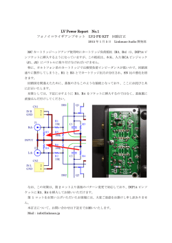
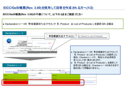
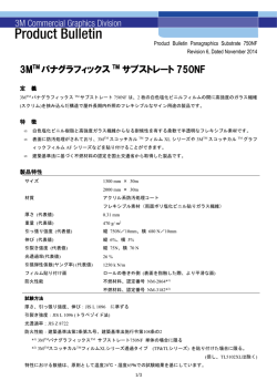
Safety Precautions
H5CN
DIGITAL TIMER
English
Instruction Manual
CAUTION
Thank you for purchasing this Omron product.
This manual primarily describes the functions, performance and
application methods needed for optimum use of the product.
Please observe the following items when using the product.
▪This product is designed for use by qualified personnel with a
knowledge of electrical systems.
▪Before using the product, thoroughly read and understand this
manual to ensure correct use.
▪Keep this manual in a safe location so that it is available for
reference whenever required.
Omron Corporation
©All Rights Reserved
2288977-4A (Side-A)
Dimensions and Installation
n INSTALLATION
n DIMENSIONS [mm]
6
48
48
14.2
7 2 .5
(10.9)
97.6
n PANEL CUTOUT [mm]
Standard panel cutout is as
shown in the right figure.
(conforms to DIN43700)
60 min.
R0.5 max.
45㧗0.6
㧙0
45㧗0.6
㧙0
60 min.
Note 1. The thickness of
mounting panel
should be 1 to 5 mm.
Note 2. It is possible to
mount the products
side-by-side. The dimension is as shown
in the right figure.
n Units mounted
side-by-side
A
A=(48n-2.5) +1
-0
Timing Chart (Power ON Delay)
Connection
● Model H5CN-@@N
(without memory backup)
Contact output

● Model H5CN-X@NS
(without memory backup)
Transistor output
Internal circuit
Gate
Reset
Contact
output
(–)
(+)
● Model H5CN-X@NM
(with memory backup)
Contact output
Reset
Transistor
output
100 to 240 VAC
12 to 48 VDC
(–)
(+)
Power ON
DO NOT
USE
Gate
Contact
output
(–)
(+)
100 to 240 VAC
24 VDC
▪ Model H5CN-@@N/X@NS: Terminal 1 is internally connected to terminal 2 if the Counter is a model that operates with DC.
Model H5CN-X@NM: Terminal 3 is internally connected to terminal 2 if the Counter is a model that operates with DC.
▪ A diode is connected between terminal 5 and 6 to absorb the counter electromotive force that occurs when connecting an
inductive load.
▪ Do not wire the terminals which are not used.
Time UP
Gate input
Setting value
0
Control output
Time up
indication
DOWN display
Power ON
0
no digital
display
Gate input
Reset input
Gate input
Digital display
00 h 00 min
(instant output)
of setting in 1/1000th of a second because there is an error
of between 0.03 to 0.05 s. (Repeat accuracy is 1 to 2 ms)
Specifications
Power supply voltage
Operating voltage range
Power consumption
External reset, gate
100 to 240 VAC 50/60 Hz
12 to 48 VDC, 24 VDC
(20% max. ripple)
85 to 110% of rated power voltage
Approx. 12 VA (for 240 VAC)
Approx. 2.5 W (for 48 VDC)
0.5 sec reset time (min.)
Reset time following power application: 0.05 sec
0.02 sec reset signal width (min.)
ON residual voltage: 2 V max.
* Contact and transistor signal input
use common terminal.
Connecting Sockets
Socket
Surface mounting
Flush mounting
P2CF-08(-E)
P3G-08
P2CF-11(-E)
P3GA-11
Self-diagnosis Function
7 segment display Time UP display
Control output
e1
OFF
Time up
indication
e2
OFF
e3
OFF
Suitability for Use
Description
CPU error
Memory error
(RAM)
Memory error
(non-volatile memory)*
Output
OFF
OFF
OFF
* Including the case when the rewriting lifespan of the nonvolatile memory is reached.
Recovery method
As an action, turn the power OFF then back ON again. If the display restored to normal, then a probable cause can be external
noise affecting the system. Check for external noise. In the case
of E3, input gate (“0000” will be displayed) and turn power ON
again. After that, if it still remains the same, the product must
be repaired.
Contact Address
OMRON EUROPE B.V.
Wegalaan 67-69, NL-2132 JD Hoofddorp The Netherlands
Phone 31-2356-81-300
FAX 31-2356-81-388
OMRON ELECTRONICS LLC
One Commerce Drive Schaumburg, IL 60173-5302 U.S.A
Phone 1-847-843-7900
FAX 1-847-843-7787
H5CN_EN-JP.indb 1
min
When an error has occurred, the bellow error codes are shown.
Power supply
Omron Companies shall not be responsible for conformity with any standards, codes or regulations which apply to the combination of the Product in the Buyer’s application or use of the Product. At Buyer’s request, Omron will provide applicable third party
certification documents identifying ratings and limitations of use which apply to the Product. This information by itself is not sufficient
for a complete determination of the suitability of the Product in combination with the end product, machine, system, or other application or use. Buyer shall be solely responsible for determining appropriateness of the particular Product with respect to Buyer’s
application, product or system. Buyer shall take application responsibility in all cases.
NEVER USE THE PRODUCT FOR AN APPLICATION INVOLVING SERIOUS RISK TO LIFE OR PROPERTY OR IN LARGE
QUANTITIES WITHOUT ENSURING THAT THE SYSTEM AS A WHOLE HAS BEEN DESIGNED TO ADDRESS THE RISKS, AND
THAT THE OMRON PRODUCT(S) IS PROPERLY RATED AND INSTALLED FOR THE INTENDED USE WITHIN THE OVERALL
EQUIPMENT OR SYSTEM.
hours
▪ Take particular care with the H5CN-@Z@, which is capable
H5CN
-@@N
-X@NS
-X@NM
Gate input
Setting value
sec
(Conceivable
operating time) 5 min 30 s
Time UP
Reset input
Set the reset time at lease 0.5 sec during power recovery (power reset).
min
(Undesirable
changes in
the settings)
250 VAC 3 A resistive load (cosφ=1)
Minimum load
10 mA, 5 VDC (P level, reference value)
Transistor output
open collector
100 mA, 30 VDC max.
Operating ambient
-10 to +55 ºC
temperature
(with no icing and condensation)
Operating ambient humidity 35 to 85% RH
Storage temperature
-25 to +65 ºC
(with no icing and condensation)
Altitude
2,000 m max.
Weight
Approx. 110 g
Electrical lifespan of
100,000 operations min.
relay
(3 A, 250 VAC resistive load)
Mechanical lifespan of relay 10,000,000 operations min.
Power supply
Connection of contact signal input Connection of transistor signal input
Reset input
Reset input
Connection of transistor signal input
Gate input
Reset input
Gate input
Connection of contact signal input
● Model H5CN-X@NM (with memory backup)
Model
H5CN-@Z@
H5CN-@A@
H5CN-@B@
H5CN-@C@
H5CN-@D@
▪ The H5CN Timer is capable of reading the input data at any time during normal operation. This means that the set time can be changed
during power application. This feature sets back the output from the
timer by temporarily setting the longer time or quickens the output by
setting the shorter time. During normal operation, the set time may
be accidentally changed by touching a thumbwheel switch, causing
the timer to operate with a different set time. To prevent this possibility, use the optional Y92A-48B Protective Cover.
▪ When the set time is all zeroes (e.g., 000.0 s or 00 h 00 min), there will
be a momentary control output upon power application, which can be
used to check normal output. When changing the set time during normal operation, pay attention not to alter the set value to this all zeroes.
▪ When changing the set time while power is being supplied, an inadequate push of the thumbwheel switches willdisplay two numbers in one
display window, causing the operating count to drift widely. Therefore,
press the thumbwheel switches surely. Take particular care when the
other three digits are all zeroes, because the improper setting of the
fourth switch to create four zeroes will cause an instantaneous output.
Control output
Contact output
Input Connection
● Model H5CN-@@N/X@NS (without memory backup)
Setting range
0.001 sec~9.999 sec
0.01 sec-99.99 sec
0.1 sec-999.9 sec
1 sec-99min59 sec
1 min-99h59 min
Reset input
Digital display
DO NOT
USE
100 to 240 VAC
12 to 48 VDC
Internal circuit
DO NOT USE
1) Inrush current will be carried when turning on the power.
If the capacity of the power for the product is insufficient,
the product cannot start. Use a power supply, breakers,
contacts which sufficient capacity.
100 to 240 VAC specifications Approx. 0.8 A for 264 VAC
12 to 48 VDC specifications Approx. 0.4 A for 52.8 VDC
2) Since 50 ms after the power is turned ON is required as the raise
time of the internal circuit voltage, note that the product may not
operate in response to any input signal during this period.
3) Since100 ms after the power is turned OFF (or momentary power failures) is required as the fall time of the
internal circuit voltage, note that the product may respond
to input signals during this period.
4) The product memorizes the status just before occurring
the electric failure memory with non-volatile memory. The
rewriting lifespan of the non-volatile memory is 1,000,000
or more. The non-volatile memory rewrites the setting
condition into the initial setting one when the power OFF
and reset input. (-M type only)
5) Model H5CN 12-48 VDC specification use transformer-less
power supply which the power terminals and input terminals are
not insulated. When use this specification, the internal parts of
the product may be occasionally burnt (damaged) if the wiring
is not correct. Pay attention to check the wiring before use.
6) Operation time setting
Time setting range
Reset, gate
Power reset
● Digital display
UP display
Reset
Internal circuit
Gate
Precautions for Correct Use
Please comply strictly with the following instructions which are
Indicates a potentially hazardous situation which, if intended to ensure safe operation of thecontroller.
1) Make sure the proper product is specified for the application.
CAUTION not avoided, is likely to result in minor or moderate
2) For correct use, do not subject the product to the following
injury or property damage.
conditions.
l Warning Symbols
• Dramatic temperature fluctuations
• High humidity or where condensation may occur
• Severe vibration and shock
Do not touch the terminals while power is being supplied.
• Where excessive dust, corrosive gas, or direct sunlight may
Doing so many occasionally result in minor injury due to
be present
electric shock.
3) This product is not waterproof or oil resistance. Do not use the
product
in any of the places subject to splashing liquid or oil
Do not use the product where subject to flammable or
atmosphere.
explosive gas.
4) Use and store the product within the rated ranges given for the
Otherwise, minor injury from explosion may occasionally occur.
product model you are using. If necessary, use forced cooling.
Never disassemble, modify or repair the product or touch
If the product is stored below −10°C, allow it to warm up for three
any of the internal parts. Minor electric shock, fire, or
hours at room temperature before turning ON the power supply.
malfunction may occasionally occur.
5) Do not cover the vent holeson the products and the area
around the product in order to ensure thermal dissipation.
The life expectancy of output relays varies considerably
6) Wiring all terminals correctly.
with the output load and switching conditions. Always consider the application conditions and use the output relays
7) Do not wire the terminals which are not used.
within their rated load and electrical life expectancy. If the
8) Use specified size crimped terminals (M3.5, thickness 7.2 mm
max.) for wiring with a gage of AWG 24 to AWG 18 (equal to a
output relays are used past their life expectancy, contact
cross section area of 0.205 to 0.823 mm2).
fusing or burning may occasionally occur. Also, never
(The
wiring stripping length is 5 to 6 mm.)
exceed the rated load current. When using a heater, surely
Up to two wires of same size and type, or two crimped termiuse a thermo switch in the load circuit.
nals can be inserted into a single terminal.
Tighten the terminal screws to between 0.74 and 0.90 N·m.
9) Use this product within the rated power supply voltage and
Loose screws may occasionally result in fire.
control output.
Do not allow pieces of metal, wire clippings, or fine metallic
10) Use a switch, relay, or other contact to turn the power supply
shavings or filings from installation to enter the product. Doing
ON instantaneously. If the voltage is applied gradually, the
so may occasionally result in electric shock, fire, or malfunction.
power may not be reset or output malfunctions may occur.
11) Do not apply the supply voltage directly from external to
transistor output.
12) Install and clearly label a switch or circuit breaker so that the
operator can quickly turn OFF the power supply.
13) Install the input signal resource and the product itself apart
from noise generating sources and wiring which is carrying
[mm]
the high power current to cause noise.
14) Separate the product from any sources of excessive static
Surface mounting
electricity, such as forming materials and pipes carrying
powder and liquid materials.
15) Interlock the power to the product with a relay so that the
@44.8
product will not be left in an output on condition for long periModel H5CN
Model H5CN
ods. Leaving the product in an output-on condition for a month
-@@N
-X@NM
or longer, especially in places with high temperatures, may
-X@NS
114.6
103.7
106
116.9
result in deterioration to internal parts, such as an electrolytic
capacitor.
16) Internal circuit voltage (5 V) is output to the no-voltage input
terminals, which may cause some connected devices to
malfunction or fail. Check the specifications of the input device
P2CF-08(-E)
P2CF-11(-E)
(e.g., rated output voltage or whether a power supply circuit
diode is built in).
To prevent power supply devices from
Flush mounting
being subjected to charging accidents,

Sensor
connect a diode as in the figure when
95.1
10.9
10.9
100.2
using a power supply voltage of 5 V or
less to operate input devices that do
not have a diode built into the power
Input
0V
supply circuit.
Model H5CN
Model H5CN
-@@N
-X@NM
17)
The
exterior
of
the
product
may
be
damaged
by
organic
sol-X@NS
+
vents (such as thinners or benzene), strong alkali, or strong
+
Adapter
Adapter
acids.
P3G-08
P3GA-11 18) Check that the LED indicators are operating normally. Depending
Y92F-30
Y92F-30
on the operating environment, the indicators and plastic parts may
deteriorate faster than expected, causing the indicators to fail.
Periodically perform inspections and replacements.
19) Use tools when separating parts for disposal.
20) When disposing of the product, observer all local ordinances
as they apply.
no digital
display
Model
Precautions for Safety Use
l Key to WARNING Symbols
OMRON ASIA PACIFIC PTE. LTD.
No. 438A Alexandra Road # 05-05/08(Lobby 2),
Alexandra Technopark, Singapore 119967
Phone 65-6835-3011
FAX 65-6835-2711
OMRON Corporation
Shiokoji Horikawa, Shimogyo-ku, Kyoto 600-8530 JAPAN
1/16/2014 11:28:16 AM
安全上のご注意
●警告表示の意味
H5CN
形
注意
クォ-ツタイマ
Japanese
正しい取扱いをしなければ、この危険のために、時
に軽傷・中程度の傷害をおったり、あるいは物的損
害を受ける恐れがあります。
●警告表示
取扱説明書
注意
このたびはオムロン製品をお買い上げいただきまして、まこと
にありがとうございます。
この取扱説明書では、本製品をご使用いただく上で必要な機
能、性能、使用方法などの情報を記載しています。
本製品のご使用に際して、下記のことを守ってください。
・この製品は電気の知識を有する専門家が扱ってください。
・この取扱説明書をよくお読みになり、十分にご理解のうえ、正
しくご使用ください。
・この取扱説明書はいつでも参照できるよう大切に保管ください。
感電により軽度の傷害が稀に起こる恐れがあります。通電
中は端子に触らないでください。
爆発により稀に軽度の傷害の恐れがあります。
引火性、爆発性ガスのある所では使用しないでください。
軽度の感電、発火、機器の故障が稀に起こる恐れがあります。
分解、改造、修理したり、内部に触らないでください。
出力リレーの寿命は、開閉容量、開閉条件により大きく異な
るので必ず実使用条件を考慮し、定格負荷、電気的寿命回数
内でご使用ください。寿命を超えた状態で使用すると接点溶
着や焼損の恐れがあります。また、負荷電流は必ず定格以下
でご使用いたただき、ヒータ等を使用する場合は、必ず負荷
回路にサーモ・スイッチをご使用ください。
発火が稀に起こる恐れがあります。端子ねじは規定トルク
(0.74~0.90N・m)で締めてください。
オムロン株式会社
軽度の感電、発火、機器の故障が稀に起こる恐れがありま
す。製品の中に金属、導線または取りつけ加工中の切粉な
どが入らないようにしてください。
©All Rights Reserved
詳細な使用方法はwww.fa.omron.co.jpへアクセスをお願いします。
2288977-4A(Side-B)
外形および取付寸法
■取付寸法 [mm]
■外形寸法 [mm]
6
表面取りつけの場合
48
@44.8
106
48
103.7
形H5CN
-X@NM
116.9
114.6
14.2
7 2 .5
(10.9)
形H5CN
-@@N
-X@NS
97.6
形P2CF-08(-E)
■パネルカット寸法 [mm]
標準パネルカットは
右図のとおりです。
(DIN43700準拠)
埋込み取りつけの場合
60以上
R0.5以下
形P2CF-11(-E)
95.1
10.9
45㧗0.6
㧙0
10.9
100.2
45㧗0.6
㧙0
60以上
注1.取り付けパネルの
板厚は1~5mmが
適当です。
注2.密着取り付け時の
パネルカット寸法
は右図のようにな
ります。
形H5CN
-@@N
-X@NS
+
アダプタ
n個密着取付け
形H5CN
-X@NM
+
アダプタ
形P3G-08
形Y92F-30
形Y92F-30
形P3GA-11
A
A=(48n-2.5) +1
-0
安全上の要点
使用上の注意
以下に示すような項目は安全を確保する上で必要なことですので
必ず守ってください。
1) ご希望通りの製品であるかお確かめの上ご使用ください。
2) 下記環境下での使用は避けてください。
・温度変化の激しい場所
・湿度が高く、結露が生じる恐れのある場所
・振動、衝撃の激しい場所
・塵埃が多い、腐食性ガスの発生する、直射日光があたる
場所
3) 本製品は防水、防油構造ではありません。水がかかる所、被
油のあるところでは使用しないでください。
4) 周囲温度および湿度は仕様範囲内で使用および保存してくだ
さい。 必要により強制冷却してください。
また、-10℃以下で保存後使用する場合は、常温に3時間以
上放置してから通電してください。
5) 放熱を妨げないよう本体の通風孔および周辺をふさがないで
ください。
6) 端子の極性を確認し、正しく配線してください。
7) 使用しない端子には何も接続しないでください。
8) 配線用圧着端子は、指定サイズ(M3.5、幅7.2mm以下)のも
のをご使用ください。裸線接続の配線材は、銅製AWG24(断
面積0.205mm2)-AWG18(断面積0.823mm2)のより線か、単線
を使用してください。
(電線被覆剥きしろ:5~6mm)
1端子への配線は同じサイズ、同じ種類の線で2本まで、圧
着端子は2枚までの接続としてください。
9) 電源電圧および制御出力は仕様、定格の範囲内でご使用くだ
さい。
10) 電源投入・遮断はスイッチ、リレーなどの接点を介して一気
に行ってください。徐々に電圧を印加しますと、誤動作の原
因となることがあります。
11) トランジスタ出力端子には外部から直接電圧を印加しないで
ください。
12) 作業者がすぐ電源をOFFできるよう、スイッチまたは
サーキットブレーカを設置し、適切に表示してください。
13) ノイズ発生源、ノイズがのった強電線から入力信号源の機
器、入力信号線の配線、および製品本体を離してください。
14) 多量の静電気が発生する環境(成形材料、粉・流体材料のパ
イプ搬送の場合など)でご使用の場合は静電気発生源を製品
本体より離してください。
15) 高温中に長時間、出力ONの状態で放置されますと、内部部品
(電解コンデンサ等)の劣化を早める恐れがあります。その
ためリレーと組み合わせて使用するようにし、長時間(例え
ば1ヶ月以上)の出力ON状態での放置はしないでください。
16) 無電圧入力端子には内部回路電圧(約5V)が出ています。接
続される入力機器によっては誤動作・故障の恐れがあります
ので、入力機器の仕様(出力定格電圧、電源回路ダイオード
内蔵有無)をご確認ください。
電源回路にダイオードが内蔵され
センサ
ていない入力機器を5V以下の電源
電圧でご使用する場合は、電源装
置への充電事故を防止するために
図のようにダイオードを接続して
入力
ください。
0V
17) 本体の外装は有機溶剤(シンナー・ベンジンなど)強アルカ
リ、強酸性物質に侵されますので使用しないでください。清
掃の際は、市販のアルコールをご使用ください。
18) 表示(LED)が正常に動作していることをご確認ください。
ご使用環境によっては、LED、樹脂部品の劣化を早め、表示
不良になることがありますので、定期的な点検および交換を
お願いします。
19) 廃棄時に分別する時は、工具を使用してください。
20) 本製品を廃棄する場合は、各地方自治体の産業廃棄物処理方
法に従って処理してください。
1) 電源投入時に短時間ですが突入電流が流れ、電源の容量
によっては起動しないことがありますので、十分な容量
の電源、ブレーカ、接点をご使用ください。
AC100-240V仕様
AC264V時 約0.8A
DC12-48V仕様
DC52.8V時 約0.4A
2) 電源投入後50ms の間は内部回路電圧の立上り時間のため、
この間の入力信号に対しては作動しないことがあります。
3) 電源開放後(停電直後)100msの間は内部回路電圧の立
下り時間のため、この間の入力信号に対しては作動して
しまうことがあります。
4) 不揮発性メモリにより停電記憶を行っており、書き込み
寿命100万回以上です。不揮発性メモリへの書き込みは
電源OFF時に行います。(-Mタイプのみ)
5) 形H5CNシリーズのDC12-48V電源タイプは電源端子と信号入
力端子間が絶縁されていない電源トランスレス方式となって
います。非絶縁タイプのDC電源を使用する場合は、配線に
よっては回り込みで、稀に内部部品の焼損(破壊)の恐れが
あります。ご使用前に配線を十分ご確認ください。
6) 動作時間の設定
時間設定範囲
設定範囲
0.001s~9.999s
0.01s~99.99s
0.1s~999.9s
1s~99min59s
1min~99h59min
・“常時読込方式”を採用しており、通電中でも設定が変
更できますので、一時的に長時間にセットして不動作状態
にしたり短時間にセットして早く動作させたりすることが
できます。
(運転中、誤って触れてセット値が変わると、変わった後の
セット値で動作することになりますので、その恐れがある場
合は別売のフロントカバー形Y92A-48Bをご使用ください。)
・セット値をオール“0”(たとえば000.0sや00h00min)にし
ますと制御出力が瞬時に出せますので、時間“ゼロ”でのテ
ストなどに使用できます。運転中、セット値を変更する場
合、オール“0”の状態にならないようにしてください。
・通電中に設定時間を変更する場合、サムロータリ・スイッチ
の数字表示窓に2つの数字が見えるような半端なプッシュ状
態を続けると動作時間が大きく狂いますので、サムロータ
リ・スイッチは確実にプッシュしてください。特に設定値
変更中の桁以外の3桁が“0”にセットされているときに、
残りの1桁を上記のような中途半端な設定をしていると瞬時
に出力が出る場合がありますのでご注意ください。
min
sec
hours
min
〔好ましく
ない設定
変更〕
〔可能性の
ある動作
00h00min
5min30s
(瞬時に出力が出ます)
時間〕
・1/1000秒設定が可能な形H5CN-□Z□タイプの場合、固定
誤差(0.03 ~0.05s)が発生する場合があります。(ただ
し、繰り返し誤差は1~2ms程度です)
定格(仕様)
電源電圧
許容電圧変動範囲
消費電力
端子配列
●形H5CN-@@N(停電記憶なし)
有接点出力
タイムチャート(パワーオンディレー)
●形H5CN-X@NS(停電記憶なし)
無接点出力
内部回路
ゲ-ト
ゲ-ト
リセット
リセット
有接点
出力
●形H5CN-X@NM(停電記憶あり)
有接点出力
●数字表示
UP表示用
リセット
内部回路
無接点
出力
電源ON
DO NOT
USE
ゲ-ト
DO NOT USE
タイムアップ
リセット入力
内部回路
有接点
出力
ゲート入力
設定値
(–)
(+)
AC100~240V
DC12~48V
(–)
(+)
AC100~240V
DC12~48V
DO NOT
USE
(–)
数
字
表
示
せ
ず
数字表示
AC100~240V
DC24V
(+)
・DC電源仕様製品の場合、停電記憶なしタイプは②-①端子、停電記憶ありタイプは③-②端子は内部で接続されています。
・形H5CN-X@NSの端子⑤-⑥間のダイオードは誘導負荷接続時発生する逆起電力の吸収用ダイオードです。
・使用しない端子には何も接続しないでください。
0
電源
制御出力
タイムアップ
表示
有接点信号入力の接続
最小電源開放時間0.5s
電源投入後のリセット時間0.05s
外部リセット、ゲート 最小リセット入力信号幅0.02s
残留電圧2V以下
※有接点・無接点入力共用
制御出力
接点出力
AC250V 3A抵抗負荷(cosφ=1)
最小適用負荷
DC5V 10mA (P水準,参考値)
トランジスタ出力
オープンコレクタ
DC30V max,100mA max
使用周囲温度
-10~+55℃
(ただし、氷結、結露しないこと)
使用周囲湿度
35~+85%
保存周囲温度
-25~+65℃
(ただし、氷結、結露しないこと)
高度
2,000m以下
質量
約110g
リレーの電気的寿命
10万回以上(AC250V,3A抵抗負荷)
リレーの機械的寿命
1,000万回以上
適用ソケット
DOWN表示用
無接点信号入力の接続
リ
セ
ッ
ト
入
力
ゲート入力
リ
セ
ッ
ト
入
力
有接点信号入力の接続
リ
セ
ッ
ト
入
力
ゲート入力
ゲート入力
ゲート入力
リ
セ
ッ
ト
入
力
ソケット
●形H5CN-X@NM(停電記憶あり)
無接点信号入力の接続
AC100~240V 50/60Hz
DC12~48V、DC24V
(リップル含有率20%以下)
定格電源電圧の85~110%
約12VA(AC240V時)
約2.5W(DC48V時)
リセット、ゲート
電源リセット
入力の接続
●形H5CN-@@N/X@NS(停電記憶なし)
形式
形H5CN-@Z@
形H5CN-@A@
形H5CN-@B@
形H5CN-@C@
形H5CN-@D@
電源ON
タイムアップ
リセット入力
設定値
数字表示
形P2CF-08(-E)
形P3G-08
形P2CF-11(-E)
形P3GA-11
7セグメント表示 タイムUP 表示
制御出力
内容
出力
OFF
CPU異常
e2
OFF
e3
OFF
メモリ異常
OFF
(RAM)
メモリ異常
OFF
(不揮発性メモリ)※
e1
OFF
※不揮発性メモリの書換寿命に達した場合も含みます。
復帰方法
電源の再投入を行ってください。表示が正常となった場合、
ノイズの影響が考えられますので、ノイズが発生していない
か確認してください。E3の場合、エラー発生時の状態を消去
する必要がありますので、ゲートを入力(“0000”を表示し
ます)し再度、電源再投入を行ってください。上記処置を行っ
ても表示が変わらない場合は修理が必要です。
タイムアップ
表示
ご使用に際してのご承諾事項
お問い合わせ先
オムロン株式会社
インダストリアルオートメーションビジネスカンパニー
●製品に関するお問い合わせ先
お客様相談室
クイック
*(a)から(d)に記載されている他、本カタログ等記載の商品は自動車(二輪車含む。以下同じ)向けではありません。自動車に搭載
する用途には利用しないで下さい。自動車搭載用商品については当社営業担当者にご相談ください。
*上記は適合用途の条件の一部です。当社のベスト、総合カタログ、データシート等最新版のカタログ、マニュアルに記載の保証・免
責事項の内容をよく読んでご使用ください。
埋込み取付け用
ソケット
異常が発生した時は下記の表示になります。
数
字
表
示
せ
ず
電源
当社商品は、一般工業製品向けの汎用品として設計製造されています。従いまして、次に掲げる用途での使用を意図しておらず、
お客様が当社商品をこれらの用途に使用される際には、当社は当社商品に対して一切保証をいたしません。ただし、次に掲げる用
途であっても当社の意図した商品用途の場合や特別の合意がある場合は除きます。
(a) 高い安全性が必要とされる用途(例:原子力制御設備、燃焼設備、航空・宇宙設備、鉄道設備、昇降設備、娯楽設備、医用機
器、安全装置、その他生命・身体に危険が及びうる用途)
(b) 高い信頼性が必要な用途(例:ガス・水道・電気等の供給システム、24時間連続運転システム、決済システムほか権利・財産
を取扱う用途など)
(c) 厳しい条件または環境での用途(例:屋外に設置する設備、化学的汚染を被る設備、電磁的妨害を被る設備、振動・衝撃を受
ける設備など)
(d) カタログ等に記載のない条件や環境での用途
表面取り付け用
ソケット
自己診断機能
ゲート入力
0
電源復帰(電源リセット)の際には電源開放時間を必ず0.5s以上とってください。
H5CN
-@@N
-X@NS
-X@NM
フリー
通話
オムロン
0120-919-066
携帯電話・PHS・IP電話などではご利用いただけませんので、下記 の電話番号へおかけください。
電話 055-982-5015(通話料がかかります)
■営業時間:8:00~21:00
■営業日:365日
●FAXやWebページでもお問い合わせいただけます。
●その他のお問い合わせ
納期・価格・サンプル・仕様書は貴社のお取引先、または貴社
担当オムロン販売員にご相談ください。
オムロン制御機器販売店やオムロン販売拠点は、Webページで
ご案内しています。
オムロン制御機器の最新情報をご覧いただけます。
www.fa.omron.co.jp
緊急時のご購入にもご利用ください。
FAX 055-982-5051 / www.fa.omron.co.jp
H5CN_EN-JP.indb 2
1/16/2014 11:28:19 AM
© Copyright 2026 Paperzz