G
For Gas
フローメータ
Online Store にて販売中!
http://www.tofco.jp/store/
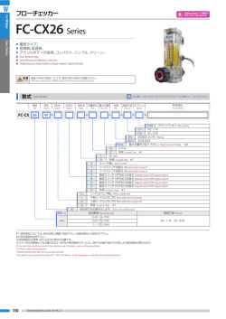
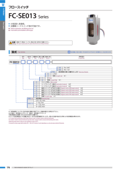
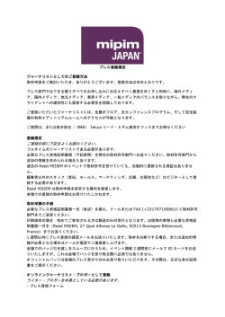
FM-PZ Series
Flowmeter
警報スイッチが取付可能です。
短納期。低価格。
■
■
Alarm switch can be installed
Quick delivery and offering at a low price.
■
■
型式
規格
Std.
FM-PZ
型式欄にご記入頂き、そのままFAXでもOK! お見積もり、ご注文承ります。
Type selection
ガス
Gas
形状1
Shape1
-
G
形状2
Shape2
流体名 流量単位 最大流量 設計圧力/温度 接続口径 オプション
Fluids
Units
Max. flow Designed pres./temp. Pipe size
Option
-
-
-
-
特殊項目
For specif item
-
T1
ショートタイプ For short type *4
FPM バイトンパッキン Viton packing
規格 Std.
接続口径 Pipe size
01
25
Rc 1/4”
02
Rc 3/8”
50
03
Rc 1/2”
1atm/20℃ 設計圧力/温度を示します Shows designed pres./temp. *3
Max.
測定範囲の最大流量をご記入下さい。 Shows here max. flowrate.
NL/min
*1: 特殊項目に付いては、型式末尾に順番に明
SL/min
記下さい。詳細は弊社にお問合せ下さい。
特殊 For specif. unit *1
G
規格 Std.
25
50
012
2014 Vol.1
B
E
Z
1
AIR
2
N2
O2
3
CO2
4
Ar
5
He
6
C3H8(プロパン) (Propane)
7
AIR/N2 ダブル目盛 Air/N2 double scale*4*5
A
特殊 For specif. fluid *1
9
0 スイッチ無し With no switch
1 リードスイッチA接点 With reed switch of Contact A *2
2 リードスイッチB接点 With reed switch of Contact B *2
A 磁気スイッチ NPN出力A接点 Magnetic switch of NPN output contact A *2
B 磁気スイッチ NPN出力B接点 Magnetic switch of NPN output contact B *2
C 磁気スイッチ PNP出力A接点 Magnetic switch of PNP output contact A *2
D 磁気スイッチ PNP出力B接点 Magnetic switch of PNP output contact B *2
9 特殊 For specif. shape *1
0
ニードルバルブ無し With no needle valve
1
下側ニードルバルブ付 With needle valve at lower side
2
上側ニードルバルブ付 With needle valve at upper side
9
特殊 For specif. shape *1
気体用である事を示します。 Shows to be used for gas.
測定範囲 Measuring range
口径 Pipe size
材質 Mtl.
1∼10NL/min
2∼20NL/min
3∼30NL/min
Rc1/4”
SCS14
4∼50NL/min
10∼100NL/min
10∼100NL/min
20∼200NL/min
Rc 3/8”
, Rc 1/2”
SCS14
30∼300NL/min
40∼400NL/min
*2: A接点:設定値以上クローズ
B接点:設定値以下クローズ
*3: 圧力、温度が1atm/20℃以外のものに付
いては、巻末の技術資料を参照下さい。
*4: 規格25のみ対応。
*5: 仕様が限定されています。お問い合わせ下
さい。
※ 測定範囲はAIR換算 1atm/20℃
{OMPa(G)}条件の流量です。
※
マークは即納品です。ただし、Air/N2ダ
ブル目盛の下記の型式に限定されます。
FM-PZ25G-10A-B□-1atm/20℃-01
※ スイッチ設定範囲は、FS流量の約20∼80
%が使用範囲です。ただし、個々の目盛や長
さや接点方式等により使用範囲は異なりま
す。
*1: For specif. items specify them at end of Type selection in order.
For details, consult us with your specification.
*2: Contact A: Switch is closed as the float rises past the switch.
Contact B: Switch is closed as the float falls past the switch.
*3: Refer to technical information at the end of this catalog, if
applying any pressure and temperature other than 1 atm and
20℃.
*4: Responding only to Std.25.
*5: Specifications to be applied are limited. Please contact us
with your specification.
※ Measuring range shown above are ones equivalent to air at 1
atm/20℃.
shows a quick delivery, however the
※ Pictorial marking
type is limited to a double scale of Air/N 2 as shown
below:FM-PZ25G-10A-B□-1atm/20℃-01
※ Set point for contact range shall be within 20%~80% of FS.
However, it varies depending on a scale, size and contact
method of flowmeter.
G
磁気スイッチ仕様
Specifications
流量精度 Flow accuracy
±5% of FS FS±5%
使用最高圧力 Max. operating pressure
0.8MPa (G)
使用流体温度 Operating fluid temperature ※
Max. 100℃ / NBR 80℃
使用環境温度 Ambient operating temperature
0∼50℃(結露なきこと) (No dewing)
フローメータ
PNP出力-A接点 PNP output contact A ※
PNP出力-B接点 PNP output contact B ※
電源電圧 Power supply voltage
DC+12∼24V
消費電流 Power consumption
10mA以下 Less than 10mA
オープンドレイン Open drain
出力 Output
耐電圧 Withstand voltage Max. 30V
駆動電流100mA以下 Driving current Less than 100mA
A接点 Contact A ※
ケーブルの長さ Cable length
B接点 Contact B ※
DC 0∼24V
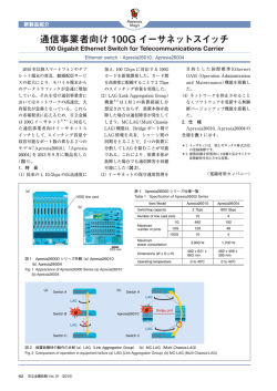
規格寸法
Max. 0.2A
2m (AWG24)
Standard dimensions
50cm (AWG24)
ケーブルの長さ Cable length
25
50
L
L1
L2
標準 Standard type
155
130
100
ショートタイプ Short type
139
115
85
標準 Standard type
185
150
112
FM-PZ
※A接点:設定値以上クローズ
B接点:設定値以下クローズ
※Contact A: Switch is closed as the float rises past the switch.
Contact B: Switch is closed as the float falls past the switch.
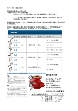
Structural drawing
FM-PZ50 type(リードスイッチ付) (with reed switch)
FM-PZ25 type(リードスイッチ付) (with reed switch)
4-M4ネジ
OUT
①
②
③
④
⑤
⑥
深さ4 (4deep)
⑫
⑦
⑧
⑨
⑩
青 Blue(−)
L
120
L1
L
茶 Brown(+)
(26)
2-Rc3/8”or 1/2”
35
2-Rc1/4”
⑪
⑫
茶 Brown(+)
(25)
青 Blue(−)
32.5
⑪
IN
50
Max.39
30
②
③
④
⑥
⑤
⑦
⑨
⑧
⑩
L1
構造図
NPN出力-B接点 NPN output contact B ※
出力形態 Output form
リードスイッチ仕様 Specifications on reed switch
接点容量 Contact capacity
Specifications on magnetic switch
NPN出力-A接点 NPN output contact A ※
※ オプションにて、
パッキン : FPM選定時。
※ Available when using FPM O-rings.
接点方法 Contact forms
気体用
仕様
32
Max.52
46
17
10
パネルカット図 For panel cut-out
PZ25 type スイッチ付 with switch
PZ50 type スイッチ付 with switch
2-φ20
2-φ29
35
磁気スイッチ Magnetic switch
※
40
L2
L1
28
35
4-φ5
15
10
5
(28)
L2
L1
オレンジ Orange : +DC12∼24V
グレー Gray : GND
ホワイト White : OUT PUT
120
100
※
(2000)
19
⑬
φ30
埋込型 For embedded type
パネルマウントタイプ
For panel mounting type
※ リードスイッチ付きの場合、磁性体パネルには固定できません。
Flowmeter equipped with reed switch is uninstallable to magnetic panel
材質 Materials
No.
名称 Names of parts
1
キャップ Cap
2
フィッティング Fittings
3
パッキン Packing
4
ストッパー Stoppers
5
ガイドポール Guiding pole
6
テーパー管 Tapered tube
材質 Mtl.
PPS
No.
名称 Names of parts
7
フロート Float
NBR
8
フロントプレート Front plate
POM/PPS/SUS316
9
ケース Case
SCS14
SUS316
耐熱ガラス Heat-resistant glass
10 ニードルバルブ Needle valve
11 ロックナット Locknut
材質 Mtl.
摘要 Remarks
SUS316/ガラス/Ti/SUS304 マグネット密封(スイッチ付のみ)
Magnet sealed for switch
SUS316/Glass/Ti/SUS304
PA12
ADC12
SUS316
オリフィス Orifice:PEEK
C3604/Ni-3
12 リードスイッチ Reed switch
SUS303 他 SUS303, etc.
AWG24
13 磁気スイッチ Magnetic switch
POM 他 POM etc.
AWG24
2014 Vol.1
013
© Copyright 2026 Paperzz