●この資料に掲載しています応用回路等は製品の特性および性能を引き出す上で正確かつ信頼
できるものと確信しております。ただし、その使用に起因する回路上および工業所有権に関
する諸問題につきましては当社は一切その責任を負いません。また、改良などのため予告な
しに仕様の変更を行うことがあります。
●カタログ記載値は参考値であり、ご使用に当たっては納入仕様書を御請求頂くか、あるいは
承認図のお取り交わしをお願い致します。
●当カタログに記載の製品用途は一般民生機器を前提としております。
●医療機器、宇宙用機器、原子力関係機器など、故障を生じた場合、人命に影響し、あるいは
社会的に甚大な損失を与える恐れのある機器に使用する電子部品は一般民生機器向けと区別
した高い信頼性が必要になる場合があります。このような用途、もしくはカタログ記載以外
の用途での使用を検討される場合は、必ず事前に弊社営業部または各支社までお問合せ下さい。
●電子部品、特に面実装用部品は、使用する回路、実装方法・材料、環境条件により信頼性が
大きな影響を受ける場合がありますので、特殊な回路、実装方法・材料、特殊な環境下での
使用を検討される場合は、必ず事前に弊社営業部または各支社までお問合せ下さい。
●このカタログの記載内容は
●無断転載禁じます。
2009年10月 現在のものです。
●We are confident that the practical circuit configurations and examples listed in
this document will ensure the maximum benefit from the characteristics and perfomance feature of our products and that these application examples are accurate and reliable. However, we cannot accept any liability for any problems in
connection with industrial property rights and concerning any difficulties arising in
the use of these circuits. It should also be noted that as part of our ongoing policy
of product improvement, the specifications given herein may be changed or modified at anytime without prior notice.
●Values mentioned in the catalog are reference purpose only. Please request
specifications for the part which you plan to use.
●Parts shown in the catalog are meant for general commercial products.
●Electronic components used in equipment that can have a serious effect on human life or society, such as medical equipment, equipment for use in space, nuclear related equipment, etc. requires higher reliability parts than those found in
general commercial electronics. For these types of applications or for other applications not mentioned in the catalog, please contact our sales department or
branch office.
●For electronic components, and especially for surface mount parts, reliability can
be affected by the circuit, mounting method and material, as well as the environmental conditions. For this reason, please contact the sales department or
branch office if you plan on manufacturing a special circuit, use special mounting
methods and materials, or if the equipment will be used in an unusual environment.
●The details given in the catalog are valid as of October.2009.
●All rights reserved.
サ
ー
ジ
ア
ブ
ソ
ー
バ
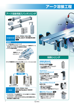
ダイヤサージシリーズは、マイクロギャップによる電界電子放出機構を応用
したサージ吸収素子です。数十μmにカットされたマイクロギャップで放電
をトリガし、主放電はキャップ電極間にて行われます。この為、急峻な立上
りをもつ、誘導雷、静電気に対してすばやく応答するので、低電圧回路・通
信回路・電源回路・エレクトロニクス機器のサージ対策に最適な製品です。
Each DIA SURGE SERIES part has a micro gap cut to an accuracy of several
tens of microns in width for rapid response against induced lightning and electrostatic discharges.These components are ideal for protecting low voltage circuits, communication systems and power supply circuits against electrical circuits as well as electronic equipment for surge voltage.
DB60
DA38
DA53
DSA
DSAZR
CSA20/CSZ20
CSA30/CSZ30
DSP
DSS
DSSV
DE37
DA33
CSA70
CDA70
■特長
■Features
●Wide voltage range(140~7800V)is available.
●Quick response for surge voltage and low limiting voltage.
●Low capacitance and very high insulation resistance.(100MΩmin.)
●Stable against repeated surges and environmental fluctuation.
●No polarity.
●No dark effect.
●Some models are recognized by UL,CSA and TÜV.
●Each part combined with a varistor or cement resistor can be used as surgeprotecting elements in power supplies.
●同一形式で、広範囲の動作電圧(140∼7800V)のものが選べます。
●サージ吸収特性が良く、制限電圧が低くなります。
●静電容量が小さく、絶縁性(10MΩ以上)も優れています。
●繰り返しサージ及び環境変化に対して安全です。
●極性がありません。
●明暗効果がありません。
●UL、CSA、TÜV規格認定品もあります。
●各種電源回路にバリスタまたは指定セメント抵抗と組合せる事により使用できます。
● RoHS 対応品です。
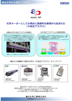
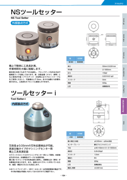
マイクロギャップ Micro gap
ガラス Glass
ガラス Glass
マイクロギャップ Micro gap
キャップ電極 Electrode cap
リード線 Lead wire
リード線 Lead wire
キャップ電極 Electrode cap
特殊皮膜 Special film
特殊ガス Special gas
特殊ガス Special gas
特殊皮膜 Special film
ダイヤサージシリーズの構造 Structure of DSA and DA38,DA53,DSP,DSS,DE37,DA33
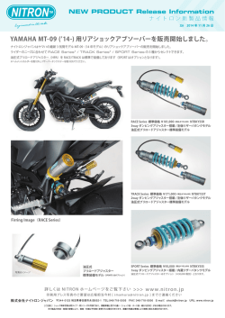
■用途 Applications
家電
Consumer
Electronics
産業機器
Industrial
サージ対策
Surge protection
エアコン、冷蔵庫、電子レンジ、給湯器
Air conditioner, Refrigirator, Microwave oven, Hot boiler
電源ライン Power line
UL, CSA, TÜV
TV、DVD
サージ耐量
Surge current capacity
1000A~5000A
工業用計測機器、各種制御機器
Process measurement & control
サージ対策
Surge protection
電 話
Telephone
情報通信
Communication
通信ライン
アンテナ
UL, CSA対策
Communication line
Antenna
UL, CSA protection
交換機、PHS基地局
PBX, Base station
携帯電話
Mobile phone
充電器
Battery charger
サージ耐量
Surge current capacity
500A~3000A
複写機、FAX
Copier, Fax
OA
IT
パソコン
PC
静電気対策
ESD protection
Modem,
ADSL、VDSL
管内放電
アンテナ
Internal discharge
Antenna
CRT
AV
Automotive
カーステレオ、
カーナビ、無線機
Car audio, Car navigation
1
DB60
DA38
DA53
DSA
DSAZR
DSANR
DSAHR
DA33
DA38
DA53
DSA
DSS,DE37
高電圧DSS
High voltage DSS
DSSV
CSA70
CDA70
DSP
高電圧DSP
High voltage DSP
CSA10
CSA20
CSZ20
CSA30
CSZ30
電源サージ対策用
For Power Lines
The DB60 Series are designed specifically for power supplies using microgap
technology to discharge surges.
With a 5mm pitch and a small body size, the part takes up very little space on
the board.
■特長
■Features
●5mmピッチのラジアルテーピング形状で自動実装に対応。
● マイクロギャップを利用した優れたサージ応答特性。
● 100MΩ以上の高い絶縁抵抗特性。
● 各種電源回路にバリスタとDB60シリーズを組合せる事により使用できます。
●The 5mm pitch; radial taped parts can be mounted using automatic
insertion equipment.
●Superior surge response characteristcs due to microgap technology.
●High insulation resistance of over 100MΩ.
●DB60 series combined with varistor can be used as surge-protecting
elements in power supplies.
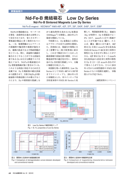
■形名構成 Part number system
−
DB60
シリーズ名
Series
272
M
直流放電開始電圧
DC Spark-over
voltage(Vs)
直流放電開始電圧許容差
DC Spark-over
voltage tolerance
最初の2数字は電圧値の有効数字で
第3数字は乗数を表す。
The first two digits are significant,
and the third is number of zeros.
M
±20%
例)272の場合
Ex.) 272 meanes:
27✕102=2700v
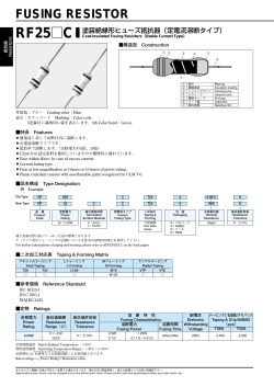
■形状・寸法
■マーキング
Dimensions
Marking
8.5 max
カラーコード
Color code
8.5 max
形 名
Part No.
Color code
32.0 max
3.85±0.5
5.0±0.5
15.0±2.5
12.7±1.0
黒
Black
茶
Brown
赤
Red
DB60-272M
だいだい
Orange
黄
Yellow
緑
Green
DB60-302M
青
Blue
DB60-362M
紫
Purple
DB60-452M
灰
Gray
白
White
■特性 Characteristics
形 名
Part No.
直流放電開始電圧
DC spark-over
voltage
Vs
DB60-272M
2700V ±20%
DB60-302M
3000V ±20%
DB60-362M
3600V ±20%
DB60-452M
4500V ±20%
絶縁抵抗
Insulation
resistance
IR
100MΩ
min.
静電容量
Electrostatic
capacitance
1kHz-6V max.
サージ耐量
Surge current
capacity
8/20µsec.
DC500V
8/20μsec.
1500A
1pF max.
DC1000V
サージ寿命
Surge life
test
8/20μsec.
100A 200times
AC耐電圧
AC withstanding
voltage
UL規格認定品
UL recognized
4)
UL1414
5)
UL1449
EN規格認定品
EN recognized
6)
EN60065
EN60950-1
AC1000V-1min.
AC1200V- 3sec.
○ 1)
○ 2)
AC1500V-1min.
○ 1)
○ 2)
○ 3)
AC1800V-3sec.
○ 1)
○ 2)
○ 3)
AC2000V-1min.
○ 1)
○ 3)
1):バリスタ(AC125V V1mA≧270V 8 Joule Min at 2ms, AC250V V1mA≧470V 8 Joule Min at 2ms)と電気的に直列接続(リード線をよりはんだ付け、
かしめ、溶接等)する事により、認定されます。
Approved if used together with a varistor (AC125V : V1mA 270V 8 Joule Min at 2ms, AC250V : V1mA 470V 8 Joule Min at 2ms), electrically connected in
series by means
such as twist and soldering, staking, welding etc.
2):バリスタ(AC125V V 1mA≧270V D≧φ5mm, AC250V V 1mA≧470V D≧φ5mm)と電気的に直列接続(リード線をよりはんだ付け、かしめ、溶接等)
する事により、認定されます。
Approved if used together with a varistor (AC125V : V1mA 270V, D φ5mm, AC250V : V1mA 470V, D φ5mm), electrically connected in series by means
such as twist and soldering, staking, welding etc.
3):バリスタ(V 1mA≧470V D≧φ5mm)と電気的に直列接続(リード線をよりはんだ付け、かしめ、溶接等)する事により、認定されます。
Approved if used together with a varistor (V1mA 470V, D φ5mm), electrically connected in series by means such as twist and soldering, staking, welding etc.
4):UL Standard UL 1414 File No. E89615
5):UL Standard UL 1449 File No. E70785 or E318314
6):DB60 has received recognition to EN60065, EN60950-1 through TÜV. Report No.J50164463
2
DB60シリーズは、マイクロギャップを利用した放電管タイプの電源用サー
ジアブソーバです。5mmピッチの小型であり、実装面積を小さく抑えること
ができます。
サ
ー
ジ
ア
ブ
ソ
ー
バ
電源サージ対策用
For Power Lines
サ
ー
ジ
ア
ブ
ソ
ー
バ
DA38シリーズはマイクロギャップによる電界電子放出機構を応用したサー
ジ用防護素子です。このためサージに対して応答性がよく、また各種AC耐電
圧試験に対応しており、サージ耐量を要する電源ラインのサージ対策に最適
のサージ吸収素子です。
DA38 Series has a micro gap cut to an accuracy of several tens of microns in
width for rapid response against induced lightning and electrostatic discharges.
Allows performing the AC withstanding voltage test.
This series are ideal for protecting power supplies against surge voltage.
■特長
■Features
●非常に小型です。
(直径 3.8mm 長さ 10mm)
●各種AC耐電圧試験に対応可能です。
●サージに対し応答性がよく、制限電圧が低くなります。
●静電容量が小さく、絶縁性にも優れています。
●繰り返しサージ及び環境変化に対して安定しています。
●アキシャルテーピング包装対応可能です。
●極性がありません。
●明所暗所による特性の差がありません。
●各種電源回路にバリスタとDA38シリーズを組合せる事により使用できます。
●Small size. ( 3.8mm Length 10mm)
●Allows performing the AC withstanding voltage test.
●Quick response for surge voltage, and low limiting voltage.
●Small capacitance and excellent insulation resistance.
●Stable for repeated discharge test conditions and environmental fluctuation.
●Axial taping available.
●No polarity.
●No dark effect.
●DA38 Series combined with varistor can be used as surge-protecting elements in power supplies.
■形名構成 Part number system
DA38
シリーズ名
Series
−
−
272
M
T
直流放電開始電圧(Vs)
DC Spark-over
voltage (Vs)
直流放電開始電圧許容差
DC Spark-over
voltage tolerance
包装形態
Packing form
±20%
M
最初の2数字は電圧値の有効数字で
第3数字は乗数を表す。
The first two digits are significant,
and the third is number of zeros.
特殊記号
Special code
B
バルク包装
Bulk pack
記号
Code
T
テーピング包装
Taping Form
無し
None
A21F
例)272の場合
Ex.) 272 means:
27×102=2700v
A21F
内容 Description
包装形態B品
Bulk pack
包装形態T品(アキシャルテーピング)5mm ピッチ
Axial Taping, Lead pitch 5mm
■形状・寸法 Dimensions
φ3.8±0.5
単位:mm
Unit:mm
φ0.50±0.05
25.5min
25.5min
10.0±1.0
■特性 Characteristics
DA38-102M
800V∼1,200V
−
−
○3)
−
EN規格
認定品
EN recognized
8)
EN60065
EN60950-1
−
DA38-152M
1,200V∼1,800V
−
−
○3)
−
−
DA38-272M
2,160V∼3,240V
AC1,000V−3sec.
AC1,200V−3sec.
○1)
○3)
○3)
−
DA38-302M
2,400V∼3,600V
AC1,500V−1min.
○1)
○3)
○3)
○4)
DA38-362M
2,880V∼4,320V
AC1,800V−3sec.
○1)
○3)
○3)
○4)
DA38-452M
3,600V∼5,400V
AC2,000V−1min.
○2)
−
−
−
DA38-622M
4,960V∼7,440V
AC3,000V−1min.
○2)
−
−
−
形 名
Part number
直流放電開始電圧
DC spark-over
voltage
Vs
絶縁抵抗
Insulation
resistance
IR
静電容量
Electrostatic
capacitance
1kHz-6V max.
サージ耐量
Surge current
capacity
8/20µsec.
8/20μsec.
2,000A
DC 500V
1pF max.
100MΩmin.
1500A
DC 1000V
サージ寿命
Surge life
test
8/20μsec.
100A
300times
200times
AC耐電圧
AC withstanding
voltage
CSA規格
認定品
CSA recognized
6)
7)
5)
UL1414 UL1449 CSA22.2
UL規格認定品
UL recognized
1):バリスタ
(AC125V V1mA≧270V 8 Joule Min at 2ms, AC250V V1mA≧470V 8 Joule Min at 2ms)
と電気的に直列接続(リード線をよりはんだ付け、
かしめ、溶接等)する事により、認定されます。
Approved if used together with a varistor (AC125V : V1mA 270V 8 Joule Min at 2ms, AC250V : V1mA 470V 8 Joule Min at 2ms), electrically connected in series by means
such as twist and soldering, staking, welding etc.
2):バリスタ
(V 1mA≧470V 8 Joule Min at 2ms)
と電気的に直列接続(リード線をよりはんだ付け、
かしめ、溶接等)する事により、認定されます。
Approved if used together with a varistor (V1mA 470V, 8 Joule Min at 2ms), electrically connected in series by means such as twist and soldering, staking, welding etc.
3):バリスタ
(AC125V V 1mA≧270V D≧φ5mm, AC250V V 1mA≧470V D≧φ5mm)
と電気的に直列接続(リード線をよりはんだ付け、
かしめ、溶接等)する事により、認定されます。
Approved if used together with a varistor (AC125V : V1mA 270V, D φ5mm, AC250V : V1mA 470V, D φ5mm), electrically connected in series by means
such as twist and soldering, staking, welding etc.
4):バリスタ
(V 1mA≧470V D≧φ5mm)
と電気的に直列接続(リード線をよりはんだ付け、
かしめ、溶接等)する事により、認定されます。
Approved if used together with a varistor (V1mA 470V, D≧φ5mm), electrically connected in series by means such as twist and soldering, staking, welding etc.
5):UL Standard UL1414 File No.E89615
6):UL Standard UL1449 File No.E70785 or E318314
7):CSA Standard C22.2 No1 File No. CA111411
8):DA38 has received recognition to EN60065, EN60950-1 through TÜV. Report No. J9950875
特殊仕様となります。別途ご相談ください。
Please consult us for available
3
電源サージ対策用
For Power Lines
DA53 Series has a micro gap cut to an accuracy of several tens of microns in
width for rapid response against induced lightning and electrostatic discharges.
Allows performing the AC withstanding voltage test.
This series are ideal for protecting power supplies against surge voltage.
■特長
■Features
●非常に小型です。
(直径 5.3mm 長さ 10mm)
●各種AC耐電圧試験に対応可能です。
●サージ耐量が大きく、3000Aです。
●サージに対し応答性がよく、制限電圧が低くなります。
●静電容量が小さく、絶縁性にも優れています。
●繰り返しサージ及び環境変化に対して安定しています。
●極性がありません。
●明所暗所による特性の差がありません。
●各種電源回路にバリスタとDA53シリーズを組合せる事により使用できます。
●Small size. ( 5.3mm Length 10mm)
●Allows performing the AC withstanding voltage test.
●Used to protect power supplies.
●Quick response for surge voltage, and low limiting voltage.
●Small capacitance and excellent insulation resistance.
●Stable for repeated discharge test conditions and environmental fluctuation.
●No polarity.
●No dark effect.
●DA53 Series combined with varistor can be used as surge-protecting elements in power supplies.
■形名構成 Part number system
DA53
シリーズ名
Series
622
M
F
直流放電開始電圧(Vs)
DC Spark-over
voltage (Vs)
直流放電開始電圧許容差
DC Spark-over
voltage tolerance
包装形態
Packing form
−
±20%
M
最初の2数字は電圧値の有効数字で
第3数字は乗数を表す。
The first two digits are significant,
and the third is number of zeros.
−
E15E
特殊記号
Special code
B
バルク包装
Bulk pack
記号
Code
F
バルクフォーミング包装
Bulk Forming pack
無し
None
E15E
例)622の場合
Ex.) 622 means:
62×102=6200v
E25E
内容 Description
包装形態B品
Bulk pack
包装形態F品(フォーミング形状E品)
リード線間 15mm
Bulk forming, Lead pitch 15mm
包装形態F品(フォーミング形状E品)
リード線間 25mm
Bulk forming, Lead pitch 25mm
■形状・寸法 Dimensions
φ5.3±0.4
25.5min
単位:mm
Unit:mm
φ0.50±0.05
10.0±1.0
25.5min
■マーキング Marking
ロットNo.(最大4桁の英数字)
Lot No. (Number with four digits maximum)
商標 Trade mark
形名略記号(最大4桁の英数字)
Part number (Number with four digits maximum)
■特性 Characteristics
形 名
Part number
直流放電開始電圧
DC spark-over
voltage
Vs
DA53-701M
560V∼840V
DA53-272M
2,160V∼3,240V
DA53-302M
2,400V∼3,600V
DA53-362M
2,880V∼4,320V
DA53-622M
4,960V∼7,440V
DA53-752M
6,000V∼9,000V
DA53-782M
6,240V∼9,360V
絶縁抵抗
Insulation
resistance
IR
静電容量
Electrostatic
capacitance
1kHz-6V max.
サージ耐量
Surge current
capacity
8/20µsec.
サージ寿命
Surge life
test
DC 250V
DC 500V
1pF max.
100MΩmin.
8/20μsec.
3,000A
DC 1,000V
8/20μsec.
100A
300times
AC耐電圧
AC withstanding
voltage
UL規格認定品
UL recognized
5)
UL1414
CSA規格認定品
CSA recognized
EN規格認定品
EN recognized
6)
7)
9)EN60065
8)
EN60950-1
UL1449 C22.2 No.1 C22.2 No.60065
−
−
−
−
AC1,000V−1min.
AC1,200V−3sec.
−
○2)
○2)
AC1,500V−1min.
○1)
○2)
○2)
AC1,800V−3sec.
○1)
○2)
○2)
AC3,000V−3sec.
○1)
−
○2)
○3)
○4)
AC3,600V−3sec.
○1)
−
○2)
○3)
○4)
AC4,000V−1min.
○1)
−
−
○4)
○4)
○4)
1):バリスタ
(AC125V V1mA≧270V 8 Joule Min at 2ms, AC250V V1mA≧470V 8 Joule Min at 2ms)
と電気的に直列接続(リード線をよりはんだ付け、
かしめ、溶接等)する事により、認定されます。
Approved if used together with a varistor (AC125V : V1mA 270V 8 Joule Min at 2ms, AC250V : V1mA 470V 8 Joule Min at 2ms), electrically connected in series by means
such as twist and soldering, staking, welding etc.
2):バリスタ(AC125V V 1mA≧270V D≧φ5mm, AC250V V 1mA≧470V D≧φ5mm)と電気的に直列接続(リード線をよりはんだ付け、かしめ、溶接等)する事により、認定されます。
Approved if used together with a varistor (AC125V : V1mA 270V, D φ5mm, AC250V : V1mA 470V, D φ5mm), electrically connected in series by means such as twist and soldering, staking, welding etc.
3):バリスタ(AC125V:V1mA 270V D φ14mm AC250V :V1mA 470V D φ14mm)と電気的に直列接続(リード線をよりはんだ付け、かしめ、溶接等)する事により、認定されます。
Approved if used together with a varistor (AC125V:V1mA 270V D φ14mm AC250V :V1mA 470V D φ14mm), electrically connected in series by means such as twist and soldering, staking, welding etc.
4):バリスタ(V1mA 470V D φ5mm)と電気的に直列接続(リード線をよりはんだ付け、かしめ、溶接等)する事により、認定されます。
Approved if used together with a varistor (V1mA 470V, D φ5mm), electrically connected in series by means such as twist and soldering, staking, welding etc.
5):UL Standard UL 1414 File No. E89615
6):UL Standard UL 1449 File No. E70785 or E318314
7):CSA Standard C22.2 No.1 File No. CA111411
8):CSA Standard C22.2 No.60065 File No. CA111411
9):DA53 has received recognition to EN60065, EN60950-1 through TÜV. Report No. J9851289(DA53-752M,782M), J9850855(DA53-302M,362M,622M)
4
DA53シリーズはマイクロギャップによる電界電子放出機構を応用したサー
ジ用防護素子です。このためサージに対して応答性がよく、また各種AC耐電
圧試験に対応しており、サージ耐量を要する電源ラインのサージ対策に最適
のサージ吸収素子です。
サ
ー
ジ
ア
ブ
ソ
ー
バ
電源サージ対策用
For Power Lines
■Features
<DSA>
■特長
サ
ー
ジ
ア
ブ
ソ
ー
バ
〈DSA〉
●通信機器、センサーライン等の低電圧低電流回路に DSA 単品で使用できます。
●The Models of this series are extensively used as surge-protecting elements for electronic equipment in low-voltage and low-current circuits such
as telecommunication equipment and sensor lines.
●Excellent for protecting signal lines that require low capacitance.
●The DSA-A-type combined with varistor or a cement resistor can be used
as surge-protecting elements in power supplies.
●Allows performing the AC withstanding voltage test without removal of the
surge absorber.
●DSA A-type series displaying the “MMCC”trademark (except 402MA,
452MA)are UL-recognized protectors when connected to the appropriate varistor (UL recognized) or a cement resistor (RGBS5 3ΩK) in-series.
(UL1449 File No.E70785 )
★Some models are approved by CSA, TÜV.
Please contact us for details.
●静電容量が小さい事から、信号ラインに使用出来ます。
●各種電源回路にバリスタまたは指定セメント抵抗とDSA-A タイプを組合せる事に
より使用できます。
●電源回路に於て、サージアブソーバを取り外さずに AC 耐電圧試験が出来ます。
(2400V 以上)
● DSA-A タイプとUL 認定バリスタまたは指定セメント抵抗(RGBS5L-3ΩK)と
組み合わせる事によりUL 規格認定品として使用出来ます。(UL1449 ファイル
No.E70785)
★一部 CSA, TÜV 認証タイプもあります。 詳しくは当社までお問い合わせ下さい。
■形名構成 Part number system
−
DSA
シリーズ名
Series
242
M
最初の2数字は電圧値の有効数字で、
第3数字は乗数を表す。
The first two digits are significant,
and the third is number of zeros.
単位:mm
Unit:mm
φ0.4∼0.5
±0.05
アキシャル形
Axial
無
None
φ0.4
M
±20%
S
アキシャル小形
Axial small
05
φ0.5
−U10T
加工品
Processed
25.0±3.0
単位:mm
Unit:mm
17.0±2.0
無
UL非認定品
UL Not recognized
ロットNo.(最大4桁の英数字)
Lot No. (Number with four digits maximum)
形名
Part number
単位:mm
Unit:mm
DSA-A-05F25 Type
4.5±1.0
22.5±2.0
F25 フォーミング品
Forming
MMCCロゴ:UL1449指定品のみ捺印されます。
通常品は、捺印されません。
MMCC Trademark
Only parts marked with the MMCC trademark
are UL1449 approved.
10.0±3.0
φ0.5±0.05
UL認定品
(UL) UL Recognized
標準品
Standard
MMCC
DSA
301L
φ0.5±0.05
φ3.8±0.4
φ0.4±0.05
無
None
単位:mm
Unit:mm
DSA-U10T Type
23.0±3.0
DSA-S Type
(UL)
UL1449認定品表示
UL1449 Recognized
A
4.0±2.0
21.0±3.0
F25
フォーミング品
Forming
U10Tタイプは2400V品まで製造可
Vs range of U10T type : 300~2400V
φ6.0±0.5
23.0±3.0
05
リード線径
Lead wire
diameter
±15%
Example Assume the designation is 242.
This means that the spark-over voltage is:24×102=2400V
DSA-A Type
形状
Shape
L
例)242の場合 24×102=2400V
■形状・寸法 Dimensions
−
A
直流放電開始電圧(Vs) 直流放電開始電圧許容差
DC Spark-over
DC Spark-over
voltage (Vs)
voltage tolerance
φ6.0±0.5
21.0±3.0
25.0±0.5
26.5±2.0
26.3±1.5
■特性 Characteristics
形状
Shape
形名
Part number
※DSA-301LA
300V
(255∼345)
※DSA-501MA
500V
(400∼600)
※DSA-701MA
700V
(560∼840)
※DSA-102MA
1000V
(800∼1200)
※DSA-152MA
1500V
(1200∼1800)
※DSA-242MA
2400V
(1920∼2880)
DSA-282MA
2800V
(2240∼3360)
A-type
S-type
直流放電開始電圧
DC spark-over
voltage
Vs
DSA-302MA
3000V
(2400∼3600)
DSA-332MA
3300V
(2640∼3960)
DSA-362MA
3600V
(2880∼4320)
DSA-402MA
4000V
(3200∼4800)
DSA-452MA
4500V
(3600∼5400)
DSA-622MA
6200V
(4960∼7440)
DSA-752MA
7500V
(6000∼9000)
DSA-301LS
300V
(255∼345)
DSA-501MS
500V
(400∼600)
DSA-701MS
700V
(560∼840)
DSA-102MS
1000V
(800∼1200)
絶縁抵抗
Insulation
resistance
lR
静電容量
Electrostatic
capacitance
1kHz-6V max.
サージ耐量
Surge current
capacity
8/20µsec.
サージ寿命
Surge life
test.
DC100V
DC250V
リード径
Lead wire
diameter
φ0.4mm
:1500A
DC500V
100MΩmin.
リード径
Lead wire
diameter
φ0.5mm
:2000A
2pF max.
DC1000V
DC100V
リード径
φ0.4mm
:1000A
DC250V
DC500V
8/20μsec.
100A
300times
CSA認証
8)
CSA approved
8)
EN認証
9)
EN approved
9)
○
−
−
○
−
−
○2)
○
−
−
−
○2)
−
−
−
−
−
○2)
−
−
−
AC1000V-1min.
AC1200V-3sec.
AC1000V-1min.
AC1250V-3sec.
○1)
○2)
−
○3)
−
○1)
○2)
−
○3)
AC1500V-1min.
○1)
○2)
−
○3)
○4)
○1)
○2)
−
○3)
○4)
○1)
○2)
−
○3)
○4)
UL規格認定品
UL recognized
AC耐電圧
AC
Withstanding
voltage
5)
UL1414
−
−
○2)
−
−
○2)
−
−
−
AC1800V-3sec.
6)
UL1449
7)
UL497B
−
AC2000V-1min.
○1)
−
−
○3)
○4)
AC2000V-1min.
○1)
−
−
○3)
○4)
AC3000V-3sec.
○1)
−
−
○3)
○4)
AC3600V-3sec.
○1)
−
−
○3)
○4)
−
−
−
○
−
−
−
−
−
○
−
−
−
−
−
○
−
−
−
−
−
−
−
−
1):バリスタ
(AC125V V1mA≧270V 8 Joule Min at 2ms, AC250V V1mA≧470V 8 Joule Min at 2ms)
と電気的に直列接続(リード線をよりはんだ付け、
かしめ、溶接等)する事により、認定されます。
Approved if used together with a varistor (AC125V : V1mA 270V 8 Joule Min at 2ms, AC250V : V1mA 470V 8 Joule Min at 2ms), electrically connected in series by means
such as twist and soldering, staking, welding etc.
2):弊社指定セメント抵抗(AC125V RGBS5L-3ΩK)または、UL認定バリスタ(AC125V:V1mA≧270V, D≧φ5mm, AC250V:V1mA≧470V, D≧φ5mm)と直列接続
(リード線をよりはんだ付け、かしめ、溶接等)する事により認定されています。
Approved if used together with a resistor (AC125V:RGBS5L-3ΩK) or a UL approved varistor (AC125V:V1mA≧270V, D≧φ5mm, AC250V:V1mA≧470V, D≧φ5mm),
electrically connected in series by means such as twist and soldering, staking, welding etc..
3):バリスタ(AC125V V 1mA≧270V D≧φ5mm, AC250V V 1mA≧470V D≧φ5mm)と電気的に直列接続(リード線をよりはんだ付け、かしめ、溶接等)する事により、認定されます。
Approved if used together with a varistor (AC125V : V1mA 270V, D φ5mm, AC250V : V1mA 470V, D φ5mm), electrically connected in series by means such as twist and soldering,
staking, welding etc.
4):バリスタ(バリスタ電圧(V 1mA):470V以上、サイズ:φ10mm以上)と電気的に直列接続する事(リード線をよりはんだ付け、かしめ、溶接等)により、認定されています。
Approved if used together with a varistor (V1mA 470V, D φ10mm), electrically connected in series by means such as twist and soldering, staking, welding etc.
5):UL Standard UL 1414 File No. E89615
6):UL Standard UL 1449 File No. E70785 or E318314
7):UL Standard UL497B File No. E175280
8):CSA Standard C22.2 No.1 File No. CA111411
9):DSA has received recognition to EN60065, EN60950-1 through TÜV. Report No. J9851289(DSA-752MA), J9251508(DSA-752MA以外の該当品種)
※ :U10Tタイプ製造可能 U10T type can be provided
5
電源サージ対策用
For Power Lines
DSAZR Series
■特長
■Features
●各種電源回路に使用出来ます。
●TVのアンテナ入力回路のサージ対策に使用出来ます。
●UL、CSA、TÜV規格認定品もあります。
●Used to protect power supplies.
●Excellent for protecting TV-tuner circuits.
●Some models are recognized by UL, CSA and TÜV.
DSAZRシリーズ
サ
ー
ジ
ア
ブ
ソ
ー
バ
■形名構成 Part number system
DSAZR
1
シリーズ名
Series
定格電圧
Rated voltage
1
AC125V
2
AC250V
−
301L
内部に使用しているDSA
,
Inside DSA s part number
■形状寸法及び包装形態 Dimensions and packing form
8.5±0.5
21.5±0.5
MMCCロゴ
Trademark
MMCC
DSAZR
形名
Part number
CSAマーク
CSA認定品のみ捺印されます。
CSA mark
Only parts marked with this
mark are CSA approved.
TÜVマーク
TÜV認定品のみ捺印されます。
TÜV mark
Only parts marked with this
mark are TÜV approved.
50
28.5±0.5
Lot.No.→
定格電圧→
Rated voltage
®
AC V
φ0.5±0.05
250
200
φ0.8±0.05 6.0±1.0
4.2
参考値
Reference value
12.5±0.5
200個/箱
200pcs./box
単位:mm
Unit : mm
■特性 Characteristics
定格電圧
Rated
voltage
AC125V
形名
Part
number
直流放電開始電圧
DC spark-over
voltage
Vs
絶縁抵抗
Insulation
resistance
lR
静電容量
サージ耐量
Electrostatic Surge current
capacitance
capacity
1kHz-6V max.
8/20µsec.
C
サージ寿命
Surge life
test.
AC耐電圧
Withstanding
voltage
EN認証
CSA規格
EN approved
認定品
CSA appoved
4)
1) 2)
3)
UL1414 UL1449
CSA22.2
UL規格認定品
UL recognized
DSAZR1-301L
500V(400∼600)
DC100V
−
−
○
−
−
DSAZR1-501M
600V(480∼720)
DC250V
−
−
○
−
−
DSAZR1-102M
1100V(880∼1320)
○
−
−
−
−
DSAZR1-242M
2400V(1920∼2880)
AC1000V-1min.
AC1200V-3sec.
○
○
○
−
DSAZR1-282M
2800V(2240∼3360)
AC1250V-3sec.
○
○
○
−
DSAZR1-302M
3000V(2400∼3600)
AC1500V-1min.
○
○
○
−
DSAZR1-362M
3600V(2880∼4320)
AC1800V-3sec.
○
○
○
−
DSAZR1-402M
4000V(3200∼4800)
AC2000V-1min.
○
○
○
−
DSAZR1-452M
4500V(3600∼5400)
DC1000V
AC2000V-1min.
○
−
○
−
DSAZR2-501M
800V(640∼960)
DC250V
−
−
○
−
−
DSAZR2-102M
1400V(1120∼1680)
−
−
○
−
−
DSAZR2-242M
2400V(1920∼2880)
AC1000V-1min.
AC1200V-3sec.
○
○
−
−
DSAZR2-302M
3000V(2400∼3600)
AC1500V-1min.
○
○
○
○
DSAZR2-362M
3600V(2880∼4320)
AC1800V-3sec.
○
○
○
○
DSAZR2-402M
4000V(3200∼4800)
AC2000V-1min.
○
○
○
○
DSAZR2-452M
4500V(3600∼5400)
AC2000V-1min.
○
−
○
○
DC500V
100MΩmin.
AC250V
2pF max.
1000A
8/20μsec.
100A
300 times
DC500V
DC1000V
1):UL Standard UL 1414 File No. E89615
2):UL Standard UL 1449 File No. E70785 or E318314
3):CSA22.2 CLASS No. 9091-32 File No. CA87070
4):DSAZR has received recognition to EN60065, EN60950-1 through TÜV. Report No. J9251508
6
電源サージ対策用
For Power Lines
サ
ー
ジ
ア
ブ
ソ
ー
バ
DSANRシリーズ
DSANR Series
■特長
■Features
●各種電源回路に使用出来ます。
●UL, TÜV規格認定品もあります。
●Used to protect power supplies.
●Some models are recognized by UL, TÜV.
■形名構成 Part number system
DSANR −
略号
Abbreviation
AC125Vライン間用
Between AC125V lines
1
(UL)
1
シリーズ名
Series
2
AC125Vラインアース間用
Between AC125V lines and ground
3
AC250Vライン間及び
ラインアース間用
Between AC250V lines or between
AC250 lines and ground
4
5
AC125Vラインアース間用
(AC1200V 絶縁耐圧試験用)
Between AC125V lines and ground
(For AC 1200V withstanding voltage test)
6
A
AC250Vラインアース間用
(AC1500V 絶縁耐圧試験用)
Between AC250V lines and ground
(For AC 1500V withstanding voltage test)
9
AC250Vラインアース間用
AC250Vラインアース間用
10
(AC1800V 絶縁耐圧試験用)
(AC2000V 絶縁耐圧試験用)
Between AC250V lines and ground B Between AC250V lines and ground
(For AC 1800V withstanding voltage test)
(For AC 2000V withstanding voltage test)
AC250Vラインアース間用
(AC2000V 絶縁耐圧試験用)
Between AC250V lines and ground
(For AC 2000V withstanding voltage test)
(UL)
UL認定品
UL Recognized
無
None
UL
非認定品
UL not
Recognized
■形状寸法及び包装形態 Dimensions and packing form
22.5
±1.0
MMCCロゴ
Trademark
8.7
±1.0
MMCC
DSANR
形名
Part number
28.1
±1.0
Lot.No.
ULマーク
UL認定品のみ捺印されます。
UL mark
Only parts marked with this
mark are UL approved.
AC 55
V
φ0.8
±0.05
15.0
最小値
Minimum
value
定格回路電圧
Rated voltage
220
200
単位:mm
Unit:mm
200個/箱
200pcs./box
15.0
±1.0
■特性 Characteristics
定格電圧
Rated
voltage
形 名
Part number
直流放電開始電圧
DC spark-over
voltage
Vs
DSANR-1
500V
(400∼600)
DSANR-2
600V
(480∼720)
絶縁抵抗
Insulation
resistance
lR
静電容量
1kHz-6V max.
Electrostatic
capacitance
1kHz-6V max.
C
サージ耐量
8/20μsec.
Surge current
capacity
8/20µsec.
サージ寿命
Surge life
test.
AC耐電圧
Withstanding
voltage
UL規格認定品
UL approved
EN認証
EN approved
3)
1) 2)
UL1414 UL1449
DC100V
−
−
○
−
−
−
○
−
DC250V
DSANR-2A
800V
(640∼960)
−
−
−
−
DSANR-2B
1100V
(880∼1320)
−
−
−
−
DSANR-4
2400V
(1920∼2880)
AC1000V-1min.
AC1200V-3sec.
○
−
−
DSANR-6
3600V
(2880∼4320)
AC1800V-3sec.
−
−
−
−
−
○
−
−
−
−
−
AC1500V-1min.
○
−
○
AC1800V-3sec.
−
−
○
AC2000V-1min.
−
−
○
AC2000V-1min.
−
−
○
AC125V
DC500V
2pF max.
100MΩmin.
800V
(640∼960)
DC250V
DSANR-3A
1400V
(1120∼1680)
DC500V
DSANR-5
3000V
(2400∼3600)
DSANR-6A
3600V
(2880∼4320)
DSANR-9
4000V
(3200∼4800)
DSANR-10B
4500V
(3600∼5400)
DSANR-3
1000A
8/20μsec.
100A
500 times
AC250V
DC500V
DC1000V
1):UL Standard UL 1414 File No. E89615
2):UL Standard UL 1449 File No. E70785 or E318314
3):DSANR has received recognition to EN60065, EN60950-1 through TÜV. Report No. J9251508
7
電源サージ対策用
For Power Lines
DSAHR Series
■特長
■Features
●大きなサージ耐量を必要とする回路の
サージ対策に使用できます。
●Used to protect power supplies.
DSAHRシリーズ
サ
ー
ジ
ア
ブ
ソ
ー
バ
■形名構成 Part number system
1
1
AC125Vライン間及びラインアース間用
Between AC125V lines or between AC125 lines and ground
略号
Abbreviation
3
AC250Vライン間及びラインアース間用
Between AC250V lines or between AC250 lines and ground
DSAHR −
シリーズ名
Series
■特性 Characteristics
定格電圧
Rated
voltage
形 名
Part number
直流放電開始電圧
DC spark-over
voltage Vs
AC125V
DSAHR-1
500V(400∼600)
絶縁抵抗
Insulation
resistance lR
静電容量
Electrostatic capacitance
1kHz-6V max.
サージ耐量
Surge current capacity
8/20µsec.
サージ寿命
Surge life
test
5pF max.
5000A
8/20μsec.
100A
300times
DC100V
100MΩmin
AC250V
800V(640∼960)
DSAHR-3
DC250V
■形状寸法及び包装形態 Dimensions and packing form
21.5±1.0
17.5±1.0
MMCC
DSAHR
MMCCロゴ
Trademark
40
形名
Part number
29.0
±1.0
Lot.No.
(See below table)
定格回路電圧
Rated voltage
AC V
250
4.0+0.5
−1.0
15.0±1.0
φ0.8±0.05
■DSAZR, DSANR, DSAHR
Lot No.表示法 Lot No. system
Lot No.表示法
205
9.0
100個/箱
100pcs./box
単位:mm
Unit:mm
■サージ応答特性(参考値)Surge response characteristics(Reference)
サージ原波形 Original waveform
1.2/50μsec. 10kV
DSA–301LA 応答波形 Response waveform
Lot No. system
Lot No.の左から第2文字:製造年の下1桁
Lot No. second character:manufactured year(Last one digit)
2kV/div.
Lot No.の左から第1文字:製造場所を示す英文字
Lot No. first character:factory
200V/div.
捺印:白色 Marking color:white
(DSAZR:gray)
Lot No.の左から第3文字:製造月
(下記参照)
Lot No. third character:manufactuerd month(See table below)
月
month 1
略号 A
Code
2
3
4
5
6
7
B
C D
E
F
G H
8
9 10 11 12
J
K
L
5μsec./div.
5μsec./div.
M
例:E5D 1995年4月製造
Example:E5D manufactuerd April,1995
Response waveform
2kV/div.
2kV/div.
DSA–242MA 応答波形
5μsec./div.
8
1μsec./div.
静電気対策用
For ESD
サ
ー
ジ
ア
ブ
ソ
ー
バ
■特長
■Features
●カーステレオ、無線機、VTR、BSチューナー等のアンテナの静電気対策に
使用できます。
●ディスプレイ装置、モニターテレビ等の管内放電対策(DSP-141Nは、除く)
に使用できます。
●その他静電気トラブル防止対策に使用できます。
●Car radio, radio cassette, wireless, new media.
●Protection from electrostatic discharge in a CRT display or monitor TV.
(Except DSP-141N)
●Protection against electrostatic discharge.
■形名構成 Part number system
−
DSP
シリーズ名
Series
−
301
N
直流放電開始電圧(Vs)
DC Spark-over
voltage(Vs)
直流放電開始電圧許容差
DC Spark-over
voltage tolerance
最初の2数字は電圧値の有効数字で
第3数字は乗数を表す。
The first two digits are significant,
and the third is number of zeros.
M
N
±20%
S
00
B
テーピング形態
Taping form
テーピング寸法
Taping dimensions
包装形態
Packing form
単位:mm
Unit:mm
A
アキシャル(横型)テーピング
Axial taping
±30%
記号
Code
04
C
例)301の場合
30×101=300v
Ex.) 301 means:
30×101=300v
ラジアル(縦型)テーピング
Radial taping
ノーテーピング
No taping
S
テープ内側幅
Taping width
ピッチ
Pitch
(ラジアルテーピング) 12.7
(Radial taping)
11
21
26
52
5
5
B
バラ品袋詰
Bulk pack
F
フラットパック
Flat pack taping
R
リール巻
Reel taping
ノーテーピング
No taping
00
■形状・寸法 Dimensions
単位:mm
Unit:mm
φ2.6±0.4
φ0.50±0.05
30.0±3.0
30.0±3.0
7.0±1.0
■マーキング Marking
第一色帯 First color band
形名 Part number
カラーコード
Color code
黒
茶
赤
だいだい
黄
緑
青
紫
灰
白
Black
Brown
Red
Orange
Yellow
Green
Blue
Purple
Gray
White
第二色帯 Second color band
製造ロット番号の10の桁 The tens dijit of product Lot No.
0
1
2
3
4
5
6
7
8
9
201M
301N
501N
751N
141N
第三色帯 Third color band
製造ロット番号の1の桁 The unit dijit of product Lot No.
0
1
2
3
4
5
6
7
8
9
■特性 Characteristics
形 名
Part number
直流放電開始電圧
DC spark-over
voltage
Vs
DSP-141N
140V(98 ∼ 182)
DSP-201M
200V(160 ∼ 240)
DSP-301N
300V(210 ∼ 390)
DSP-501N
500V(350 ∼ 650)
DSP-751N
750V(525 ∼ 975)
絶縁抵抗
Insulation
resistance
IR
静電容量
Electrostatic capacitance
1kHz-6V max.
C
サージ寿命
Surge life
test
DC 50V
DC 100V
100MΩmin.
1pF max.
DC 250V
9
1500pF-0Ω-10kV
200 times
静電気対策用
For ESD
■V–t特性(参考値) V–t Characteristics (Reference)
サ
ー
ジ
ア
ブ
ソ
ー
バ
10
Ne-Tube-80(Dark mode)
電圧
voltage (kV)
5
2
1
1
Ne-Tube-80(Light mode)
DSP-201M
0.5
0.2
0.1
0.01
0.1
1
5
時間 time (µsec.)
・急峻な立上りの静電気に対して素早い応答特性を示します。
・明暗効果がありません。
· Rapid response against electrostatic discharge with instantaneous rise.
· No dark effect.
■静電気応答特性(参考値) Electrostatic response characteristics (Reference)
静電気原波形 Original waveform
500pF–500Ω–10kV
2kV/div.
2kV/div.
DSP– 201M 応答波形(明所、暗所)
DSP– 201M Response waveform (Light & Dark mode)
1μsec./div.
1μsec./div.
Ne管(80V)応答波形(暗所)
Ne–Tube-80V Response waveform (Dark mode)
2kV/div.
2kV/div.
Ne管(80V)応答波形(明所)
Ne–Tube-80V Response waveform (Light mode)
1μsec./div.
1μsec./div.
10
静電気対策用
新製品
NEW
10
サ
ー
ジ
ア
ブ
ソ
ー
バ
10
For ESD
CSA10シリーズ(1608形状)はチップタイプの静電気対策用サージアブソー
バです。当社が永年培って参りましたマイクロギャップ方式を採用している
ため、優れたサージ応答特性と1pF以下という低静電容量を実現。小型であ
りながら、IEC61000-4-2に十分対応できる150pF-330Ω-15kVの静電気サージ
寿命を有しています。
CSA10 Series(EIA 0603 size) is a chip type surge absorber for protection
from ESD (electrostatic discharge). Through our long history of developing microgap products, we have been able to realize a product with excellent surge
protection characteristics and low capacitance of less than 1pF. Even with its
small package design, it is easily able to meet the electrostatic protection requirements of IEC61000-4-2.
■特長
■Features
●高密度表面実装対応の静電気対策用サージアブソーバ
●フロー・リフローはんだに対応
●マイクロギャップを利用した優れたサージ応答特性
●低静電容量により高周波回路上での使用が可能
●高絶縁抵抗特性
●エンボステーピング対応
●IEC61000-4-2規格準拠
●ESD surge absorber in a compact surface mount package
●Can be used with flow or reflow solder
●Microgap technology gives excellent surge response
●Can use in high frequency circuits due to low capacitance
●High insulation resistance characteristics
●Available in embossed taping
●Conforms with IEC61000-4-2 standard
■形名構成 Part number system
CSA10 −
シリーズ名
Series
−
141
N
直流放電開始電圧(Vs)
DC Spark-over
voltage(Vs)
直流放電開始電圧許容差
DC Spark-over
voltage tolerance
最初の2数字は電圧値の有効数字で
第3数字は乗数を表す。
The first two digits are significant,
and the third is number of zeros.
T
テーピング形態
Taping form
N ±30%
+30%
−20%
Q
B
バラ品
Bulk
T
テーピング
Taping
例)141の場合
14×101=140v
Ex)141 means:
14×101=140v
■形状・寸法(mm) Dimensions (mm)
L1
■推奨ランドパターン Recommended Land Pattern
L2
T
W
L
1.20mm
L 1.65±0.20
W 1.85±0.20
T 1.85±0.20
L1.L1 0.4±0.20 (mm)
1.00mm
3.00mm
銅箔(Copper)
■特性 Characteristics
形 名
Part number
CSA10-141N
直流放電開始電圧
DC Spark-over voltage
絶縁抵抗
Insulation resistance
静電容量
Electrostatic capacitance
1kHz-6V max.
Vs
IR
C
140V(98∼182)
100MΩmin.
DC 50V
1pF max.
サージ寿命(接触放電)
Surge life test
(Contact discharge)
150pF-330Ω-15kV
20 times
■IEC61000-4-2について
■About IEC61000-4-2
●静電気放電イミュニティ試験
150pF−330Ω−2∼8kV (接触放電)
2∼15kV (気中放電)
CSA20は、これに十分対応できる150pF−330Ω−15kVの
静電気サージ寿命を有しております。
●Electrostatic discharge immunity test
150pF−330Ω−2∼8kV (Contact discharge)
2∼15kV (Air discharge)
CSA20 series is easily able to meet requirements of IEC61000-4-2.
■はんだ付け条件は93頁をご参照下さい。
Please refer to page 93 for soldering conditions.
11
静電気対策用
20
20
For ESD
CSA20 Series(EIA 0805 size) is a chip type surge absorber for protection
from ESD (electrostatic discharge). Through our long history of developing microgap products, we have been able to realize a product with excellent surge
protection characteristics and low capacitance of less than 1pF. Even with its
small package design, it is easily able to meet the electrostatic protection requirements of IEC61000-4-2.
■特長
■Features
●高密度表面実装対応の静電気対策用サージアブソーバ
●フロー・リフローはんだに対応
●マイクロギャップを利用した優れたサージ応答特性
●低静電容量により高周波回路上での使用が可能
●高絶縁抵抗特性
●エンボステーピング対応
●IEC61000-4-2規格準拠
●ESD surge absorber in a compact surface mount package
●Can be used with flow or reflow solder
●Microgap technology gives excellent surge response
●Can use in high frequency circuits due to low capacitance
●High insulation resistance characteristics
●Available in embossed taping
●Conforms with IEC61000-4-2 standard
■形名構成 Part number system
CSA20 −
シリーズ名
Series
−
201
N
直流放電開始電圧(Vs)
DC Spark-over
voltage(Vs)
直流放電開始電圧許容差
DC Spark-over
voltage tolerance
最初の2数字は電圧値の有効数字で
第3数字は乗数を表す。
The first two digits are significant,
and the third is number of zeros.
T
テーピング形態
Taping form
N ±30%
+30%
−20%
Q
B
バラ品
Bulk
T
テーピング
Taping
例)201の場合
20×101=200v
Ex)201 means:
20×101=200v
■形状・寸法(mm) Dimensions (mm)
L1
■推奨ランドパターン Recommended Land Pattern
L2
T
W
L
1.65mm
L 2.0±0.2
W 1.25±0.2
T 1.25±0.2
L1.L1 0.4±0.25 (mm)
1.2mm
4.0mm
銅箔(Copper)
■特性 Characteristics
形 名
Part number
直流放電開始電圧
DC Spark-over voltage
絶縁抵抗
Insulation resistance
静電容量
Electrostatic capacitance
1kHz-6V max.
Vs
IR
C
CSA20-141N
140V(98∼182)
CSA20-201N
200V(140∼260)
CSA20-401Q
400V(320∼520)
サージ寿命(接触放電)
Surge life test
(Contact discharge)
DC 50V
100MΩmin.
DC 100V
1pF max.
150pF-330Ω-20kV
20 times
DC 250V
■IEC61000-4-2について
■About IEC61000-4-2
●静電気放電イミュニティ試験
150pF−330Ω−2∼8kV (接触放電)
2∼15kV (気中放電)
CSA20は、これに十分対応できる150pF−330Ω−20kVの
静電気サージ寿命を有しております。
●Electrostatic discharge immunity test
150pF−330Ω−2∼8kV (Contact discharge)
2∼15kV (Air discharge)
CSA20 series is easily able to meet requirements of IEC61000-4-2.
■はんだ付け条件は93頁をご参照下さい。
Please refer to page 93 for soldering conditions.
12
CSA20シリーズ(2125形状)はチップタイプの静電気対策用サージアブソー
バです。当社が永年培って参りましたマイクロギャップ方式を採用している
ため、優れたサージ応答特性と1pF以下という低静電容量を実現。小型であ
りながら、IEC61000-4-2に十分対応できる150pF-330Ω-20kVの静電気サージ
寿命を有しています。
サ
ー
ジ
ア
ブ
ソ
ー
バ
静電気対策用
30
サ
ー
ジ
ア
ブ
ソ
ー
バ
30
For ESD
CSA30シリーズ(3216形状)
はチップタイプの静電気対策用サージアブソーバ
です。当社が永年培って参りましたマイクロギャップ方式を採用しているた
め、優れたサージ応答特性と1pF以下という低静電容量を実現。小型であり
ながら、IEC61000-4-2に十分対応できる150pF-330Ω-25kVの静電気サージ
寿命を有しています。
CSA30 Series (EIA 1206 size) is a chip type surge absorber for protection
from ESD (electrostatic discharge). Through our long history of developing microgap products, we have been able to realize a product with excellent surge
protection characteristics and low capacitance of less than 1pF. Even with its
small package design, it is easily able to meet the electrostatic protection requirements of IEC61000-4-2.
■特長
■Features
●高密度表面実装対応の静電気対策用サージアブソーバ
●フロー・リフローはんだに対応
●マイクロギャップを利用した優れたサージ応答特性
●低静電容量により高周波回路上での使用が可能
●高絶縁抵抗特性
●エンボステーピング対応
●IEC61000-4-2規格準拠
●ESD surge absorber in a compact surface mount package
●Can be used with flow or reflow solder
●Microgap technology gives excellent surge response
●Can use in high frequency circuits due to low capacitance
●High insulation resistance characteristics
●Available in embossed taping
●Conforms with IEC61000-4-2 standard
■形名構成 Part number system
CSA30 −
シリーズ名
Series
−
201
N
直流放電開始電圧(Vs)
DC Spark-over
voltage(Vs)
直流放電開始電圧許容差
DC Spark-over
voltage tolerance
最初の2数字は電圧値の有効数字で
第3数字は乗数を表す。
The first two digits are significant,
and the third is number of zeros.
N ±30%
+30%
−20%
Q
T
テーピング形態
Taping form
B
バラ品
Bulk
T
テーピング
Taping
例)201の場合
20×101=200v
Ex)201 means:
20×101=200v
■形状・寸法(mm) Dimensions (mm)
L1
■推奨ランドパターン Recommended Land Pattern
L2
2.0mm
T
W
L
L 3.2±0.2
W 1.6±0.2
T 1.6±0.2
L1.L1 0.5±0.25 (mm)
2.2mm
5.0mm
銅箔(Copper)
■特性 Characteristics
形 名
Part number
直流放電開始電圧
DC Spark-over voltage
絶縁抵抗
Insulation resistance
静電容量
Electrostatic capacitance
1kHz-6V max.
Vs
IR
C
CSA30-141N
140V(98∼182)
CSA30-201N
200V(140∼260)
CSA30-401Q
400V(320∼520)
サージ寿命(接触放電)
Surge life test
(Contact discharge)
DC 50V
10MΩmin.
DC 100V
1pF max.
150pF-330Ω-25kV
20 times
DC 250V
■IEC61000-4-2について
■About IEC61000-4-2
●静電気放電イミュニティ試験
150pF−330Ω−2∼8kV (接触放電)
2∼15kV (気中放電)
CSA30は、これに十分対応できる150pF−330Ω−25kVの
静電気サージ寿命を有しております。
●Electrostatic discharge immunity test
150pF−330Ω−2∼8kV (Contact discharge)
2∼15kV (Air discharge)
CSA30 series easily able to meet requirements of IEC61000-4-2.
■はんだ付け条件は93頁をご参照下さい。
Please refer to page 93 for soldering conditions.
13
車両ECU用
新製品
NEW
20
20
For Automotive ECU
CSZ20 Series (EIA 0805 size) is a chip type surge absorber for automotive
ECU protection from ESD (electrostatic discharge). Through our long history
of developing microgap products, we have been able to realize a product with
excellent surge protection characteristics and low capacitance of less than
1pF. Even with its small package design, it is easily able to meet the electrostatic protection requirements of ISO10605.
■特長
■Features
●高密度表面実装対応の静電気対策用サージアブソーバ
●フロー・リフローはんだに対応
●マイクロギャップを利用した優れたサージ応答特性
●低静電容量により高周波回路上での使用が可能
●高絶縁抵抗特性
●エンボステーピング対応
●ISO10605規格準拠
●ESD surge absorber in a compact surface mount package
●Can be used with flow or reflow solder
●Microgap technology gives excellent surge response
●Can use in high frequency circuits due to low capacitance
●High insulation resistance characteristics
●Available in embossed taping
●Conforms with ISO10605 standard
■形名構成 Part number system
CSZ20 −
シリーズ名
Series
−
201
N
直流放電開始電圧(Vs)
DC Spark-over
voltage(Vs)
直流放電開始電圧許容差
DC Spark-over
voltage tolerance
最初の2数字は電圧値の有効数字で
第3数字は乗数を表す。
The first two digits are significant,
and the third is number of zeros.
T
テーピング形態
Taping form
N ±30%
B
バラ品
Bulk
T
テーピング
Taping
例)201の場合
20×101=200v
Ex)201 means:
20×101=200v
■形状・寸法(mm) Dimensions (mm)
L1
■推奨ランドパターン Recommended Land Pattern
L2
T
W
L
1.65mm
L 2.0±0.2
W 1.25±0.2
T 1.25±0.2
L1.L1 0.4±0.25 (mm)
1.2mm
4.0mm
銅箔(Copper)
■特性 Characteristics
形 名
Part number
CSZ20-201N
直流放電開始電圧
DC Spark-over voltage
絶縁抵抗
Insulation resistance
静電容量
Electrostatic capacitance
1kHz-6V max.
Vs
IR
C
200V(140∼260)
100MΩmin.
DC 100V
1pF max.
サージ寿命
Surge life
test
330pF-2kΩ-15kV
±10 times
■ISO10605について
■About ISO10605
●路上走行車 静電気による電気的妨害の試験方法
330pF−2kΩ−4∼8kV (接触放電)
4∼15kV (気中放電)
CSZ30は、これに十分対応できる330pF−2kΩ−15kVの
静電気サージ寿命を有しております。
●Road vehicles-Test methods for electrical disturbances from
electostatic discharge
330pF−2kΩ−4∼8kV (Contact discharge)
4∼15kV (Air discharge)
CSZ30 series easily able to meet requirements of ISO10605.
■はんだ付け条件は93頁をご参照下さい。
Please refer to page 93 for soldering conditions.
14
CSZ20シリーズ(2125形状)
はチップタイプの車両ECU静電気対策用サージア
ブソーバです。当社が永年培って参りましたマイクロギャップ方式を採用し
ているため、優れたサージ応答特性と1pF以下という低静電容量を実現。小
型でありながら、ISO10605に十分対応できる330pF-2kΩ-15kVの静電気サー
ジ寿命を有しています。
サ
ー
ジ
ア
ブ
ソ
ー
バ
車両ECU用
30
サ
ー
ジ
ア
ブ
ソ
ー
バ
30
For Automotive ECU
CSZ30シリーズ(3216形状)
はチップタイプの車両ECU静電気対策用サージア
ブソーバです。当社が永年培って参りましたマイクロギャップ方式を採用し
ているため、優れたサージ応答特性と1pF以下という低静電容量を実現。小
型でありながら、ISO10605に十分対応できる330pF-2kΩ-25kVの静電気サー
ジ寿命を有しています。
CSZ30 Series (EIA 1206 size) is a chip type surge absorber for automotive
ECU protection from ESD (electrostatic discharge). Through our long history
of developing microgap products, we have been able to realize a product with
excellent surge protection characteristics and low capacitance of less than
1pF. Even with its small package design, it is easily able to meet the electrostatic protection requirements of ISO10605.
■特長
■Features
●高密度表面実装対応の静電気対策用サージアブソーバ
●フロー・リフローはんだに対応
●マイクロギャップを利用した優れたサージ応答特性
●低静電容量により高周波回路上での使用が可能
●高絶縁抵抗特性
●エンボステーピング対応
●ISO10605規格準拠
●ESD surge absorber in a compact surface mount package
●Can be used with flow or reflow solder
●Microgap technology gives excellent surge response
●Can use in high frequency circuits due to low capacitance
●High insulation resistance characteristics
●Available in embossed taping
●Conforms with ISO10605 standard
■形名構成 Part number system
CSZ30 −
シリーズ名
Series
−
201
N
直流放電開始電圧(Vs)
DC Spark-over
voltage(Vs)
直流放電開始電圧許容差
DC Spark-over
voltage tolerance
最初の2数字は電圧値の有効数字で
第3数字は乗数を表す。
The first two digits are significant,
and the third is number of zeros.
T
テーピング形態
Taping form
N ±30%
B
バラ品
Bulk
T
テーピング
Taping
例)201の場合
20×101=200v
Ex)201 means:
20×101=200v
■形状・寸法(mm) Dimensions (mm)
L1
■推奨ランドパターン Recommended Land Pattern
L2
2.0mm
T
W
L
L 3.2±0.2
W 1.6±0.2
T 1.6±0.2
L1.L1 0.5±0.25 (mm)
2.2mm
5.0mm
銅箔(Copper)
■特性 Characteristics
形 名
Part number
CSZ30-201N
直流放電開始電圧
DC Spark-over voltage
絶縁抵抗
Insulation resistance
静電容量
Electrostatic capacitance
1kHz-6V max.
Vs
IR
C
200V(140∼260)
100MΩmin.
DC 100V
1pF max.
サージ寿命
Surge life
test
330pF-2kΩ-25kV
±10 times
■ISO10605について
■About ISO10605
●路上走行車 静電気による電気的妨害の試験方法
330pF−2kΩ−4∼8kV (接触放電)
4∼15kV (気中放電)
CSZ30は、これに十分対応できる330pF−2kΩ−25kVの
静電気サージ寿命を有しております。
●Road vehicles-Test methods for electrical disturbances from
electostatic discharge
330pF−2kΩ−4∼8kV (Contact discharge)
4∼15kV (Air discharge)
CSZ30 series easily able to meet requirements of ISO10605.
■はんだ付け条件は93頁をご参照下さい。
Please refer to page 93 for soldering conditions.
15
静電気対策用
For ESD
■Features
●非常に小型であるにもかかわらず、放電開始電圧が高電圧です。
(1000, 1500, 2700, 3000Vの4品種)
●DSP-272MはAC1200V-3秒又はAC1000V-1分、DSP-302MはAC1500V-1分
のAC試験に対応可能です。
●静電気サージに対し吸収性がよく、制限電圧が低くなります。
●静電容量が小さく、絶縁性(100MΩ以上)にも優れています。
●繰り返し静電気サージ及び環境変化に対して安定しています。
●極性がありません。
●High DC spark-over voltage
(4types; 1000, 1500, 2700, 3000V) in spite of compact size.
●DSP-272M and DSP-302M each correspond to 1200volts rms 3seconds or
1000volts rms 1minute and 1500volts rms 1minute AC withstanding voltage
tests respectively.
●Quick response for electrostatic surge and low limiting voltage.
●Small capacitance and excellent insulation resistance (100M Ω min)
●Stable for repeated electrostatic test conditions and environmental fluctuation.
●No polarity.
●No dark effect.
●明所暗所による特性の差がありません。
■代表的用途
■Typical applications
●ディスプレイ装置、モニターテレビ等の管内放電対策
●コードレス電話の充電端子
●Protect driver IC and transistors in CRT displays and TV monitors from internal electrostatic discharge.
●Cordless telephone charging terminal.
■形名構成 Part number system
DSP
−
272
シリーズ名
Series
直流放電開始電圧(Vs)
DC Spark-over
voltage(Vs)
最初の2数字は電圧値の有効数字で、
第3数字は乗数を表す。
−
M
直流放電開始電圧許容差
DC Spark-over
voltage tolerance
M
±20%
The first two digits are significant,
and the third is number of zeros.
A
21
R
テーピング形態
Taping form
テーピング寸法
Taping dimensions
包装形態
Packing form
A
アキシャル(横型)テーピング
Axial taping
記号
Code
テープ内側幅
taping width
ピッチ
Pitch
S
ノーテーピング
No taping
11
21
26
52
5
5
2=2700V
ノーテーピング
No taping
00
例)272の場合 27×10
Ex.) 272 means : 27✕102=2700V
B
バラ品袋詰
Bulk pack
F
フラットパック
Flat pack taping
R
リール巻
Reel taping
■形状・寸法 Dimensions
単位:mm
Unit:mm
φ2.6±0.4
φ0.50±0.05
30.0±3.0
30.0±3.0
7.0±1.0
■マーキング Marking
カラーコード
黒
茶
赤
だいだい
黄
緑
青
紫
灰
白
第一色帯 First color band
形名 Part number
102M
152M
272M
302M
Color code
Black
Brown
Red
Orange
Yellow
Green
Blue
Purple
Gray
White
第二色帯 Second color band
製造ロット番号の1の位 The unit digit of lot number
0
1
2
3
4
5
6
7
8
9
■特性 Characteristics
形 名
Part number
直流放電開始電圧
DC spark-over voltage
Vs(V)
DSP-102M
DSP-152M
1,000V(800∼1,200)
1,500V(1,200∼1,800)
DSP-272M
2,700V(2,160∼3,240)
DSP-302M
3,000V(2,400∼3,600)
絶縁抵抗
Insuration resistance
IR
100MΩmin.
DC500V
静電容量
Electrostatic capacitance
1kHz-6V max.
1pF max.
サージ耐量
Surge current
capacity
8/20μsec-300A
サージ寿命
Surge life test
1,500pF-0Ω-10kV
200 times
AC耐電圧
AC withstanding
voltage
なし
(nothing)
なし
(nothing)
AC1,000V-1min.
AC1,200V-3sec.
AC1,500V-1min.
16
■特長
サ
ー
ジ
ア
ブ
ソ
ー
バ
静電気対策用
For ESD
■V–l特性(参考値) V–l Characteristics (Reference)
DSP–302M
3000
放電電圧 Discharge voltage(V)
DSP–272M
放電電圧 Discharge voltage(V)
2000
1000
Glow discharge region
グロー放電
3000
2000
1000
Glow discharge region
グロー放電
Arc discharge region
アーク放電
0
10–3
10–2
Arc discharge region
アーク放電
0
10–1
10–3
放電電流(A)
Discharge current (A)
10–2
放電電流(A)
Discharge current (A)
■静電気応答特性(参考値) Electrostatic response characteristics (Reference)
2kV/div.
静電気原波形 Original waveform
500pF–500Ω–10kV
5μsec./div.
2kV/div.
DSP–272M応答波形
DSP–272M Response waveform
5μsec./div.
DSP–302M応答波形
DSP–302M Response waveform
2kV/div.
サ
ー
ジ
ア
ブ
ソ
ー
バ
5μsec./div.
17
10–1
通信サージ対策用
For Communication Lines
■Features
●電話機、モデム、FAX等電話回線に接続される機器のサージ対策。
●コンピュータ等の通信回路に接続される機器のサージ対策。
●UL規格認定品もあります。
●Surge protection for telephone lines.(telephone, modem, facsimile etc.)
●Surge protection for telecommunication lines.(computer etc.)
●Some models are recognized by UL.
■形名構成 Part number system
−
DSS
シリーズ名
Series
−
301
L
直流放電開始電圧
DC Spark-over
voltage(Vs)
直流放電開始電圧許容差
DC Spark-over
voltage tolerance
S
00
B
テーピング形態
Taping form
テーピング寸法
Taping dimensions
包装形態
Packing form
単位:mm Unit:mm
最初の2数字は電圧値の有効数字で
第3数字は乗数を表す。
The first two digits are significant,
and the third is number of zeros.
L
M
A アキシャル(横型)テーピング
Axial taping
±15%
±20%
例)301の場合
30×101=300v
Ex.) 301 meanes:
30✕101=300v
■形状・寸法
記号
Symbol
テープ内側幅
Taping width
ピッチ
Pitch
C
ラジアル(縦型)テーピング
Radial taping
04
ラジアルテーピング
Radial taping
S
ノーテーピング
No taping
12
22
26
52
B
バラ品袋詰
Bulk pack
12.7
F
フラットパック
Flat pack taping
10
10
R
リール巻
Reel taping
ノーテーピング
No taping
00
Dimensions
単位:mm
Unit:mm
φ3.3±0.4
φ0.50±0.05
30.0±3.0
7.0±1.0
30.0±3.0
■マーキング Marking
カラーコード
Color code
黒
茶
赤
だいだい
黄
緑
青
紫
灰
白
Black
Brown
Red
Orange
Yellow
Green
Blue
Purple
Gray
White
第二色帯 Second color band
製造ロット番号の10の桁 The tens digit of product Lot No.
0
1
2
3
4
5
6
7
8
9
第一色帯 First color band
形名 Part number
201M
301L
401M
601M
351M
第三色帯 Third color band
製造ロット番号の1の桁 The unit digit of product Lot No.
0
1
2
3
4
5
6
7
8
9
■特性
形 名
Part number
直流放電開始電圧
DC spark-over
voltage
Vs
DSS-201M
200V(160∼240)
DSS-301L
300V(255∼345)
DSS-351M
350V(280∼420)
DSS-401M
400V(320∼480)
DSS-601M
600V(480∼720)
絶縁抵抗
Insulation
resistance
IR
静電容量
Electrostatic
capacitance
1kHz-6V max.
サージ耐量
Surge current
capacity
8/20µsec.
サージ寿命
Surge life
test
UL 497B 2)
○
DC 100V
100MΩmin.
○
1pF max.
DC 250V
UL規格認定品
UL recognized
500A
DOC1サイクル 1)
DOC 1cycle
−
○
○
1)
:DOC 1cycle 10/1000μsec. 1KV-12times, 100/1000μsec. 1KV-12times respectively.
2)
:UL Standard UL 497B File No. E175280
18
■特長
サ
ー
ジ
ア
ブ
ソ
ー
バ
通信サージ対策用
For Communication Lines
サ
ー
ジ
ア
ブ
ソ
ー
バ
DSSVシリーズ
DSSV Series
■特長
■Features
●電話機、モデム、FAX 等電話回線に接続される機器のサージ対策及び過電
圧対策(UL1459、CSA-22.2 No.225-M90)に使用できます。
●Protects telephone line equipment (telephone, modem, facsimile etc.)
against surge and overvoltage (UL1459, CSA-22.2 No. 225-M90).
■形名構成
Part number system
DSSV −
301
L
直流放電開始電圧(Vs)
DC Spark-over
voltage(Vs)
直流放電開始電圧許容差
DC Spark-over
voltage tolerance
シリーズ名
Series
最初の2数字は電圧値の有効数字で
第3数字は乗数を表す。
The first two digits are significant,
and the third is number of zeros.
■形状・寸法
−
L
±15%
M
±20%
YD
形状
Shape
YD
横型 4端子
4Terminal
Dimensions
DSSV-YD Type
上面 Top view
側面 Side view
9.0±0.5
10.5±0.5
底面 Bottom view
4.0±1.0
5.0±0.5
0.5±0.1
DSSV-301L-YD
1
形名
Part number
MMCC □□□
18.0±0.5
12.5±0.5
4
2
Lot No.
MMCC ロゴ
Trade mark
3
φ0.7±0.1
単位:mm
Unit:mm
■特性 Characteristics
形 名
Part number
直流放電開始電圧
DC spark-over
voltage
Vs
DSSV-201M-YD
200V(160∼240)
DSSV-301L-YD
300V(255∼345)
DSSV-401M-YD
400V(320∼480)
絶縁抵抗
Insulation
resistance
IR
静電容量
Electrostatic
capacitance
1kHz-6V max.
C
サージ耐量
Surge current
capacity
8/20µsec.
UL規格認定品
UL recognized
UL 497A 3)
FCCサイクル 1)
FCC cycle 1)
DC 100V
100MΩmin.
サージ寿命
Surge life
test
2pF max.
400A
DC 250V
DOC1サイクル 2)
DOC 1cycle 2)
○
○
1)
:FCC10/560μsec. 100A ±3times, 10/160μsec. 200A ±3times
2)
:DOC 1cycle 10/1000μsec. 1KV-12times, 100/1000μsec. 1KV-12times respectively.
3)
:UL Standard UL 497A File No. E131010
■DSSVタイプ過電圧遮断特性 Overvoltage cut off properties of DSSV type
形 名
Part number
印加条件
Applied conditions
発火率
Rate of ignition n=100
DSSV–301L–YD, DSSV–401M–YD
AC600V–40A–1.50sec.
AC600V–7A–5sec.
AC600V–2.2A–30min.
0
0
0
電話機の安全規格、UL60950、CSA–C22.2 No.225–M90において、上記のよ
うな過電圧を電話機の通信回線に印加する試験があります。このような過電
圧に対して、DSSVシリーズは素早く動作し、通信回線又はサージアブソー
バに流れ込む過電圧を遮断します。
Overvoltage testing is required in both UL60950 and CSA–C22.2 No.225–M90.
The DSSV is effective in protecting against these overvoltage conditions by
opening the circuit.
19
通信サージ対策用
For Communication Lines
■サージ応答特性(参考値) Surge Response characteristics (Reference)
サージ原波形 Original waveform
FCC 10/560μsec. 800V
サ
ー
ジ
ア
ブ
ソ
ー
バ
200V/div.
200V/div.
DOC 10/1000μsec. 1000V
10μsec./div.
10μsec./div.
応答波形 Response waveform
DSS–301L, DSSV–301L–YD
FCC 10/560μsec. 800V印加
200V/div.
200V/div.
DSS–401L, DSSV–401M–YD
DOC 10/1000μsec. 1000V印加
10μsec./div.
10μsec./div.
200V/div.
バリスタ Varistor 390V
200V/div.
バリスタ Varistor 270V
10μsec./div.
10μsec./div.
20
通信サージ対策用
For Communication Lines
Glass tube type surge asorber with a micro-gap, protects many kind of communication equipment. This protection device has quick response against
surge and its capacitance value is less than 1pF.
It is suitable for high speed communications like broadband interenet.
■特長
■Features
●サージに対し吸収性がよく、制限電圧が低くなります。
●静電容量が小さく、絶縁性(100MΩ以上)にも優れています。
●Quick response for surge voltage and limiting voltage.
●Small capacitance and excellent insulation resistance (100M min)
■形名構成 Part number system
DA33 −
シリーズ名
Series
−
301
L
H
直流放電開始電圧
DC Spark-over
voltage(Vs)
直流放電開始電圧許容差
DC Spark-over
voltage tolerance
特殊記号
Special code
S
00
B
テーピング形態
Taping form
テーピング寸法
Taping dimensions
包装形態
Packing form
単位:mm Unit:mm
最初の2数字は電圧値の有効数字で
第3数字は乗数を表す。
The first two digits are significant,
and the third is number of zeros.
L
±15%
高速応答品
High responce
H
例)301の場合
30×101=300v
Ex.) 301 meanes:
30✕101=300v
■形状・寸法
A アキシャル(横型)テーピング
Axial taping
記号
Symbol
テープ内側幅
Taping width
ピッチ
Pitch
B
バラ品袋詰
Bulk pack
C
ラジアル(縦型)テーピング
Radial taping
04
ラジアルテーピング
Radial taping
12.7
F
フラットパック
Flat pack taping
S
ノーテーピング
No taping
12
22
26
52
10
10
R
リール巻
Reel taping
ノーテーピング
No taping
00
Dimensions
単位:mm
Unit:mm
φ3.3±0.4
φ0.50±0.05
30.0±3.0
30.0±3.0
7.0±1.0
■特性 Characteristics
形 名
Part number
直流放電開始電圧
DC spark-over
voltage
Vs
DA33-301LH
300V±15%
絶縁抵抗
Insuration resistance
IR
100MΩmin.
DC100V
静電容量
Electrostatic
capacitance
1kHz-6V max.
サージ耐量
Surge current
capacity
8/20µsec.
UL規格認定品
UL recognized
1pF max.
500A
○
1)
:UL Standard UL 497B File No. E175280
■サージ応答特性(参考値) Surge response characteristics (Reference)
1.2/50μ sec. 10kV サージに対する応答波形
Response wave form against 1.2/50μsec. 10kV
DSS-301L(当社従来品)
Micro-gap type
DA33-301LH
Much quicker than the old type DSS-301L.
200V/div.
200V/div.
従来品(右図)に比べて応答電圧を4割
低減。特に応答特性に優れたシリコンタイプ
(下図)に近い特性を達成。
5μsec./div.
5μsec./div.
バリスタ
(270V)
Varistor
200V/div.
サイリスタタイプ(310V)
Thyristor type 200V/div.
サ
ー
ジ
ア
ブ
ソ
ー
バ
DA33-301LHは、マイクロギャップを利用した放電管タイプの通信回線用サ
ージアブソーバです。1pF以下という優れた静電容量特性はそのままに、サ
ージ応答特性(サージ侵入時の応答電圧)を大幅に向上しました。ブロード
バンド等の高速通信分野に最適なサージ対策部品です。
5μsec./div.
5μsec./div.
21
UL 497B 1)
通信サージ対策用
For Communication Lines
■Features
●High DC spark-over voltage in spite of compact size (2types; 2700, 3000V) .
●DSS-272M and DSS-302M each correspond to 1200volts rms 3seconds or
1000volts rms 1minute and 1500volts rms 1minute AC withstanding voltage
tests respectively.
●Quick response for surge voltage and low limiting voltage.
●Small capacitance and excellent insulation resistance (100MΩmin)
●Stable for repeated discharge test conditions and environmental fluctuation.
●No polarity.
●No dark effect.
●This series are recognized under UL 1414, UL1449, CSA and TÜV.
■代表的用途
■Typical applications
●ACアダプタのサージ
●TV、VTRアンテナ回路
●通信回線(T、R∼GNDにAC耐圧試験がある場合)
●AC Adaptor.
●Antenna-circuit of TV, VCR.
●Communication lines. (If T, R~GND AC withstanding test is required.)
■形名構成 Part number system
DSS
−
272
シリーズ名
Series
直流放電開始電圧(Vs)
DC Spark-over
voltage(Vs)
最初の2数字は電圧値の有効数字で、
第3数字は乗数を表す。
−
M
直流放電開始電圧許容差
DC Spark-over
voltage tolerance
M
A
22
R
テーピング形態
Taping form
テーピング寸法
Taping dimensions
包装形態
Packing form
A アキシャル(横型)テーピング
Axial taping
±20%
The first two digits are significant,
and the third is number of zeros.
ノーテーピング
No taping
S
テープ内側幅
Taping width
ピッチ
Pitch
B
バラ品袋詰
Bulk pack
12
22
26
52
10
10
F
フラットパック
Flat pack taping
R
リール巻
Reel taping
00
例)272の場合 27×102=2700V
Ex.) 272 means : 27×102=2700V
■形状・寸法
記号
Code
ノーテーピング
No taping
Dimensions
単位:mm
Unit:mm
φ3.3±0.4
φ0.50±0.05
30.0±3.0
7.0±1.0
30.0±3.0
■マーキング Marking
カラーコード
黒
茶
赤
だいだい
黄
緑
青
紫
灰
白
第二色帯 Second color band
製造ロット番号の1の位 The unit digit of lot number
0
1
2
3
4
5
6
7
8
9
第一色帯 First color band
形名 Part number
Color code
Black
Brown
Red
Orange
Yellow
Green
Blue
Purple
Gray
White
272M
302M
■特性 Characteristics
形 名
Part number
直流放電開始電圧
DC spark-over voltage
Vs(V)
DSS-272M
2,700V(2,160∼3,240)
DSS-302M
絶縁抵抗
Insuration resistance
IR
100MΩmin.
DC500V
静電容量
Electrostatic capacitance
1kHz-6V max.
サージ耐量
Surge current
capacity
サージ寿命
AC耐電圧
Surge life test AC withstanding
voltage
1pF max.
8/20μsec-500A
8/20μsec50A AC1,200V-3sec.
AC1,000V-1min.
300回
300 times
AC1,500V-1min.
3,000V(2,400∼3,600)
UL規格認定品 CSA規格
EN認証
UL approved
EN approved
CSA
8)
approved
6)
5)
7)
UL1414 UL1449
○1)
○2)
○3)
○1)
○2)
○3)
−
○4)
1):UL認定バリスタ(V 1mA≧270V 8 Joule Min at 2ms)と電気的に直列接続(リード線をよりはんだ付け、かしめ、溶接等)する事により、認定されます。
Approved if used together with an UL approved varistor (V1mA 270V), electrically connected in series by means such as twist and soldering, staking, welding etc.
2):UL認定バリスタ(V1mA≧270V D≧φ5mm)と電気的に直列接続(リード線をよりはんだ付け、かしめ、溶接等)する事により、認定されます。
Approved if used together with an UL approved varistor (V1mA 270V D≧φ5mm), electrically connected in series by means such as twist and soldering, staking, welding etc.
3):バリスタ(AC125V V 1mA≧270V D≧φ5mm, AC250V V 1mA≧470V D≧φ5mm)と電気的に直列接続(リード線をよりはんだ付け、かしめ、溶接等)
する事により、認定されます。
Approved if used together with a varistor (AC125V : V1mA 270V, D φ5mm, AC250V : V1mA 470V, D φ5mm), electrically connected in series by means such as twist and soldering,
staking, welding etc.
4):バリスタ(V 1mA≧470V D ≧φ10mm)と電気的に直列接続(リード線をよりはんだ付け、かしめ、溶接等)する事により、認定されます。
Approved if used together with a varistor (V1mA 470V, D φ10mm), electrically connected in series by means such as twist and soldering, staking, welding etc.
5):UL Standard UL1414 File No.E89615
6):UL Standard UL1449 File No.E70785 or E318314
7):CSA Standard C22.2 No1 File No. CA111411
8):DSS-302M has received recognition to EN60065, EN60950-1 through TÜV. Report No J9750615.
22
■特長
●非常に小型であるにもかかわらず、放電開始電圧が高電圧です。
(2700, 3000Vの2品種)
●DSS-272MはAC1200V-3秒またはAC1000V-1分、DSS-302MはAC1500V-1
分のAC耐圧試験に対応可能です。
●サージに対し吸収性がよく、制限電圧が低くなります。
●静電容量が小さく、絶縁性(100MΩ以上)にも優れています。
●繰り返しサージ及び環境変化に対して安定しています。
●極性がありません。
●明所暗所による特性の差がありません。
●本シリーズはUL1414, UL1449, CSA, TÜV認定品です。
サ
ー
ジ
ア
ブ
ソ
ー
バ
通信サージ対策用
For Communication Lines
■V–l特性(参考値) Characteristics (Reference)
DSS–272M
DSS–302M
3000
放電電圧 Discharge voltage(V)
3000
放電電圧 Discharge voltage(V)
2000
Glow discharge region
グロー放電
1000
Arc discharge region
アーク放電
0
10–3
10–2
2000
Glow discharge region
グロー放電
1000
Arc discharge region
アーク放電
10–1
0
放電電流 Discharge current(A)
10–3
10–2
放電電流 Discharge current(A)
■サージ応答特性(参考値) Surge Response characteristics (Reference)
2kV/div.
サージ原波形
Original waveform
1.2/50μsec.10kV
1μsec./div.
DSS–272M応答波形
2kV/div.
DSS–272M Response waveform
1μsec./div.
DSS–302M応答波形
DSS–302M Response waveform
2kV/div.
サ
ー
ジ
ア
ブ
ソ
ー
バ
1μsec./div.
23
10–1
通信サージ対策用
For Communication Lines
The DE37 series surge absorbers have a 5mm pitch and are ideal for power
lines and communication networks. This compact device can handle surges
of up to 1500A(8/20μsec.) and is available in several voltages ranging from
300V to 4500V.The 400V part meets the standard for ADSL POTS* splitters:
ITU-T(International Telecommunication Union test standard) K.20 and K.21
Basic Test Condition, and has already received good response from both
service providers and home users in ADSL splitters.
■特長
■Features
●5mmピッチのラジアルテーピング形状で自動実装に対応(部品高さを15.5mm
以下に抑えました)。(2700V以上の品種は除く)
●アキシャルテーピングも選べます
(ガラス管を寝かせて自動実装することも
できます)
。
●1pF以下という低静電容量で、メガビットクラスの高速通信信号を阻害しませ
ん。
●マイクロギャップを利用した優れたサージ応答特性。
●100MΩ以上の高い絶縁抵抗特性。
●The 5mm pitch; radial taped parts can be mounted using automatic
insertion equipment (the part is lower than 15.5mm).
(except the item of over 2700V)
●Also available in axial taping (the glass tube can be mounted flat using
automatic insertion equipment).
●Can be used on megabit class high speed without attenuation of signal due
a capacitance value of less than 1pF.
●Superior surge response characteristics due to microgap technology.
●High insulation resistance of over 100MΩ.
■形名構成 Part number system
DE37
−
シリーズ名
Series
−
401
W
直流放電開始電圧
DC Spark-over
voltage(Vs)
直流放電開始電圧許容差
DC Spark-over
voltage tolerance
S
00
B
テーピング形態
Taping form
テーピング寸法
Taping dimensions
包装形態
Packing form
単位:mm Unit:mm
最初の2数字は電圧値の有効数字で
第3数字は乗数を表す。
The first two digits are significant,
and the third is number of zeros.
例)401の場合
40×101=400v
Ex.) 401 meanes:
40✕101=400v
■形状・寸法
L
±15%
M
±20%
W
A アキシャル(横型)テーピング
Axial taping
テープ内側幅
Taping width
12.7
10
10
D
ラジアル(縦型)テーピング
Radial taping
04
ラジアル(縦型)テーピング
Radial taping
S
ノーテーピング
No taping
12
22
26
52
+20%
−15%
記号
Symbol
00
ピッチ
Pitch
B
バラ品袋詰
Bulk pack
F
フラットパック
Flat pack taping
ノーテーピング
No taping
Dimensions
単位:mm
Unit:mm
φ0.50±0.05
φ3.7±0.4
30.0±3.0
7.0±1.0
30.0±3.0
■特性 Characteristics
形 名
Part number
直流放電開始電圧
DC spark-over
voltage
Vs
DE37-301L
300V±15%
DE37-351M
350V±20%
DE37-401W
400V(+20%,−15%)
DE37-501M
500V±20%
DE37-102M
1,000V±20%
DE37-272M
2,700V±20%
DE37-302M
3,000V±20%
DE37-362M
3,600V±20%
DE37-452M
4,500V±20%
絶縁抵抗
Insulation
resistance
IR
静電容量
サージ耐量
Electrostatic Surge current
capacitance
capacity
1kHz-6V max. 8/20µsec.
サージ寿命
Surge life
test
AC耐電圧
Withstanding
Voltage
EN規格認定品
EN recognized
UL規格認定品
UL recognized
UL 497B 5) UL1414 6)UL1449 7) EN60065 8)
EN60950-1
○
DC 100V
○
8/20μsec.
100A 300times
DC 250V
○
○
1pF max.
100MΩmin.
1500A
(8/20μsec.)
DC 500V
−
8/20μsec.
100A 200times
DC 1000V
AC1000V-1min.
AC1200V-3sec
−
○ 1)
○ 3)
AC1500V-1min.
−
○ 1)
○ 3)
○ 4)
AC1800V-3sec
−
○ 1)
○ 3)
○ 4)
AC2000V-1min.
−
○ 2)
−
○ 4)
1):バリスタ
(AC125V V1mA≧270V 8 Joule Min at 2ms, AC250V V1mA≧470V 8 Joule Min at 2ms)
と電気的に直列接続(リード線をよりはんだ付け、
かしめ、溶接等)する事により、認定されます。
Approved if used together with a varistor (AC125V : V1mA 270V 8 Joule Min at 2ms, AC250V : V1mA 470V 8 Joule Min at 2ms), electrically connected in series by means
such as twist and soldering, staking, welding etc.
2):バリスタ
(V 1mA≧470V 8 Joule Min at 2ms)
と電気的に直列接続(リード線をよりはんだ付け、
かしめ、溶接等)する事により、認定されます。
Approved if used together with a varistor (V1mA 470V, D φ5mm), electrically connected in series by means such as twist and soldering, staking, welding etc.
3):バリスタ
(AC125V V 1mA≧270V D≧φ5mm, AC250V V 1mA≧470V D≧φ5mm)
と電気的に直列接続(リード線をよりはんだ付け、
かしめ、溶接等)する事により、認定されます。
Approved if used together with a varistor (AC125V : V1mA 270V, D φ5mm, AC250V : V1mA 470V, D φ5mm), electrically connected in series by means
such as twist and soldering, staking, welding etc.
4):バリスタ
(V 1mA≧470V D≧φ5mm)
と電気的に直列接続(リード線をよりはんだ付け、
かしめ、溶接等)する事により、認定されます。
Approved if used together with a varistor (V1mA 470V, D φ5mm), electrically connected in series by means such as twist and soldering, staking, welding etc.
5):UL Standard UL 497B File No. E175280
6):UL Standard UL 1414 File No. E89615
7):UL Standard UL 1449 File No. E70785 or E318314
8):DE37 has received recognition to EN60065, EN60950-1 through TÜV. Report No.J50164439
■ITU-T K.20 Basic Test Conditionについて ●サ−ジ試験
10/700μsec 1.5kV/4kV(25Ω)±5回
●AC誘導試験
AC600V(600Ω)1sec. 5回
●AC混触試験
AC230V(10∼1000Ω)
15min.
但し、AC230V印加時にDE37-401Wは動作しません。
■Basic Conditions for ITU-T K.20
●Surge Test: 10/700μsec, 1.5kV/4kV (25Ω), 5 times.
●AC Induced Test : AC600V (600Ω), 1sec., 5 times.
●AC Cross Test: AC230V(10~1000Ω), 15min.
(however, AC230 is too low for the DE37-401W to react)
24
DE37シリーズは5mmピッチ実装に対応した電源線・通信回線用サージアブ
ソーバです。小型でありながら、1500A(8/20μsec.)のサージ耐量を有し、
動作電圧300∼4500V品をシリーズ化しました。400V品はADSL POTS*スプ
リッタ用視格:ITU-T(国際電気通信連合 試験規格)K.20あるいはK.21の
Basic Test Condition対応製品として、既に日本国内をはじめ多くのお客様に
局側あるいは宅側ADSLスプリッタ用にご好評頂いております。
※ POTS:Plain Old Telephone Service
サ
ー
ジ
ア
ブ
ソ
ー
バ
通信サージ対策用
For Communication Lines
■特長
■Features
● 4032形状の小型チップで、自動実装、フロー・リフローはんだに対応。
● マイクロギャップを利用した優れたサージ応答特性。
● 0.6pF以下という低静電容量で、メガビットクラスの高速通信信号を阻害
しません。
● 100MΩ以上の高い絶縁抵抗特性。
● 端子電極はすずメッキで、完全鉛フリー対応品です。
● UL497B取得済み
●Standard small chip package (EIA 1612, height 2.3+/-0.2mm), for use with
standard place and reflow solder equipment.
●Superior surge response characteristics from microgap technology.
●Low capacitance of less than 0.6pF means no appreciable attenuation on
high-speed, megabit class communication signals.
●High insulation resistance of over 100Mohm.
●Use tin plated electrodes and are completely lead free.
■形名構成 Part number system
CSA70 −
シリーズ名
Series
−
401
L
直流放電開始電圧(Vs)
DC Spark-over
voltage(Vs)
直流放電開始電圧許容差
DC Spark-over
voltage tolerance
最初の2数字は電圧値の有効数字で
第3数字は乗数を表す。
The first two digits are significant,
and the third is number of zeros.
T
テーピング形態
Taping form
L ±15%
M ±20%
B
バラ品
Bulk
T
テーピング
Taping
例)401の場合
40×101=400v
Ex)401 means:
40×101=400v
■推奨ランドパターン Recommended Land Pattern
■形状・寸法(mm) Dimensions (mm)
L1
L2
3.50mm
T
W
L
L 4.0±0.2
W 3.2±0.2
T 2.3±0.2
L1.L2 0.4±0.2 (mm)
2.9mm
銅箔(Copper)
4.85mm
■特性 Characteristics
形 名
Part number
直流放電開始電圧
DC Spark-over voltage
CSA70-301L
300V±15%
CSA70-401L
400V±15%
CSA70-601M
600V±20%
絶縁抵抗
Insuration resistance
IR
Vs
静電容量
Electrostatic capacitance
1kHz-6V max.
C
サージ耐量
Surge current
capacity
サージ寿命
Surge life
test
8/20μsec-1500A
8/20μsec-50A
300 times
DC100V
UL規格認定品
UL recognized
UL 497B 1)
○
100MΩmin.
0.6pF max.
DC250V
○
○
1)
:UL Standard UL 497B File No. E175280
■サージ応答特性(参考値)Surge Response Characteristics (Reference)
10/700μ sec. 4kV サージに対する応答波形
Response waveform against 10/700μsec. 4kV
CSA70-401L
サイリスタタイプ
Thyristor type 350V
バリスタ
Varistor 390V
100V/div.
100V/div.
CSA70シリーズは応答特性に優れた半導
体タイプに近い応答特性を実現。
100V/div.
サ
ー
ジ
ア
ブ
ソ
ー
バ
CSA 70 Series is a chip type surge absorber for protecting communication
networks. Through our long history of developing microgap products, we have
been able to realize a product with excellent surge protection characteristics
and low capacitance of less than 0.6pF. Even with its small package design, it
is easily able to withstand 1,500A (8/20μsec.) surges. Meets the standard for
ADSL POTS* splitters, in accordance with ITU-T (International Telecommunication Union test standard) K.20 and K.21 Basic Test Conditions.
*POTS : Plain Old Telephone Service
CSA70シリーズはチップタイプの通信回線用サージアブソーバです。当社が
永年培って参りましたマイクロギャップ方式を採用しているため、優れたサ
ージ応答特性と0.6pF以下という低静電容量を実現。小型でありながら、
1,500A(8/20μsec.)のサージ耐量を有しています。400V品はADSL POTS*
スプリッタ用規格:ITU−T(国際電気通信連合 試験規格)K.20あるいは
K.21のBasic Test Conditionに対応しています。
10μsec./div.
10μsec./div.
25
10μsec./div.
通信サージ対策用
For Communication Lines
■挿入損失特性(参考値) Insertion loss properties (Reference)
Insertion loss(dB)
2
As can be seen in the figure on the left, the CSA70 series can be used on
megabit class lines without in bibiting the high-speed signals due to a low capacitance of less than 0.6pF.
-5
3
-10
1CSA70シリーズ
2Varistor
3Sidactor
-15
-20
1
10
100
1,000
Frequency/MHz
■ITU-T K.20 or K21 Basic Test Condition for CSA70-401L(Reference)
サージ試験:10/700μ sec. 1.5kV / 4kV(25Ω)±5回
Surge Test
応答波形 Response waveform
10/700μsec. 1.5kV
応答波形 Response waveform
10/700μsec. 4kV
100V/div.
100V/div.
本試験において、CSA70-401Lは、サージ
電圧に対し瞬時に応答し、機器の誤動作、
破壊を防ぎます
10μsec./div.
10μsec./div.
AC誘導試験:AC600V(600Ω)1sec. 5回
Power induction Test
600
左図に示すように、本試験において、CSA70−401Lの放電開始電圧が低下すること
はありません。また、絶縁抵抗、静電容量にも変化は生じません。
Vs(V)
500
As seen in the figure on the left, through out the test, the breakdown voltage
never decreases, Furthermore, there is no charge in the insulation resistance
or capacitance of the part.
400
300
200
0
1
2
3
4
5
印加回数(回)
Surge(times)
AC混触試験:AC230V (10∼1000Ω) 15min.
Power cross Test
但し、AC230V印加時にCSA70-401Lは動作しません。
However, AC230V is too low for CSA70-401L to react.
上記のように、CSA70−401LはADSL POTS*スプリッタ用規格:ITU−T(国際電気通信連合 試験規格)K.20あるいはK.21のBasic Test Conditionに対応しています。
As mentioned above, CSA70-401L correspond to ITU-T (International / Telecommunication Union Test Standard) K.20 or K.21 Basic Test Conditions for the
ADSL POTS* spliter standard
■はんだ付け条件は93頁をご参照下さい。
Please refer to page 93 for soldering conditions.
26
左図に示すように、CSA70シリーズは、0.6pF以下という低静電容量のため、
メガビッ
トクラスの高速通信信号を阻害しません。
1
0
サ
ー
ジ
ア
ブ
ソ
ー
バ
通信サージ対策用
新製品
NEW
For Communication Lines
サ
ー
ジ
ア
ブ
ソ
ー
バ
CDA70シリーズはチップタイプの通信回線用サージアブソーバです。
優れたサージ応答特性と0.6pF以下という低静電容量を実現。
4032形状の小型低背チップでありながら8/20μs-2,000Aのサージ破壊耐量を
有しています。
CDA70 Series is a chip type surge absorber for protecting communication networks with excellent surge protection characteristics and low capacitance
less than 0.6pF. Even with its small package design, it is easily able to withstand 2,000A (8/20μsec.) surge.
■特長
■Features
●4032形状の小型チップで自動実装に対応
●フロー、リフローはんだに対応
●優れたサージ応答性
●高周波回路での使用に最適
●0.6pFという低静電容量
●100MΩ以上の高い絶縁抵抗特性
●UL1449規格取得済み
●RoHS対応品
● Standard small chip package; EIA 1612, height; 2.3±0.2mm
using automatic equipment
● Can be used with flow or reflow solder
● Low capacitance of less than 0.6pF means no appreciable
attenuation on high-speed, megabit class communication signals.
● Excellent insulation resistance over 100Mohm
● Recognized UL1449
● RoHS directive conformable
■形名構成 Part number system
CDA70 −
シリーズ名
Series
302
M
直流放電開始電圧(Vs)
DC Spark-over
voltage(Vs)
直流放電開始電圧許容差
DC Spark-over
voltage tolerance
最初の2数字は電圧値の有効数字で
第3数字は乗数を表す。
The first two digits are significant,
and the third is number of zeros.
−
M ±20%
T
M
テーピング形態
Taping form
マーキング
Marking
B
バラ品
Bulk
T
テーピング
Taping
例)302の場合
30×102=3000v
Ex)302 means:
30×102=3000v
■形状・寸法(mm) Dimensions (mm)
L1
■推奨ランドパターン Recommended Land Pattern
L2
T
W
L
3.50mm
L 4.0±0.2
W 3.2±0.2
T 2.3±0.2
L1.L2 0.4±0.2 (mm)
2.9mm
4.85mm
銅箔(Copper)
■特性 Characteristics
形 名
Part number
CDA70-302M
直流放電開始電圧
DC Spark-over voltage
Vs
2,400∼3,600
絶縁抵抗
Insuration resistance
IR
静電容量
Electrostatic capacitance
1kHz-6V max.
C
100MΩmin.
DC500V
0.6pF max.
1)
:UL Standard UL 1449 File No. E318314
2)
:CDA 70 has received recognition to EN60065, EN60950-1 through TÜV. Report No.J50164470
27
サージ耐量
Surge current
capacity
サージ寿命
Surge life
test
AC耐電圧
Withstanding
Voltage
2000A
(8/20μsec)
100A 300times
(8/20μsec)
AC1500V-1min.
UL規格認定品
UL recognized
EN規格認定品
EN recognized
UL 1449 1)
EN60065 2)
EN60950-1
○
○
■包装数量・包装形態 Packing quantity·Packing form
CSA20,CSZ20,CSA30,CSZ30:数量 CSA70,CDA70:数量
CSA20,CSZ20,CSA30,CSZ30
CSA70,CDA70/Unit quantity
/Unit quantity
CSA10:数量
CSA10/Unit quantity
DSA:数量
DSA/Unit quantity
DA53:数量
DA53/Unit quantity
DA38:数量
DA38/Unit quantity
A type:100個/袋
A type:100pcs/bag
バラ袋詰め
Bulk packing in
plastic bag
B type:500個/袋
B type: 500pcs/bag
B type:500個/袋
B type: 500pcs/bag
F type:100個/袋
F type:100pcs/bag
S type:200個/袋
S type:200pcs/bag
B type:1000個/袋
B type:1000pcs/bag
DB60:数量
DB60/Unit quantity
-05F25:100個/袋
-05F25:100pcs/bag
-E15E:100個/袋
-E15E:100pcs/bag
B type:200個/袋
B type:200pcs/bag
-E25E:100個/袋
-E25E:100pcs/bag
-U10T:100個/袋
-U10T:100pcs/bag
A21F:800個/箱
A21F:800pcs/box
アキシャルテーピング(箱詰め)
Axial taping (in box)
1000個/箱
1000pcs/box
ラジアルテーピング(箱詰め)
Radial taping (in box)
SMDテーピング(リール巻)
SMD taping (in reel)
T type:4000個/リール
T type:4000pcs/reel
T type:2000個/リール
T type:2000pcs/reel
高電圧DSP:数量
High voltage DSP
/Unit quantity
DSP:数量
DSP/Unit quantity
形 態
Form
高電圧DSS:数量
High voltage DSS
/Unit quantity
DSS:数量
DSS/Unit quantity
バラ袋詰め
Bulk packing in
plastic bag
DE37:数量
DE37/Unit quantity
DA33:数量
DA33/Unit quantity
S00B:200個/袋
S00B:200pcs/bag
A11F:2000個/箱
A11F:2000pcs/box
A21F:2000個/箱
A21F:2000pcs/box
A12F:2000個/箱
A12F:2000pcs/box
A22F:2000個/箱
A22F:2000pcs/box
A21F:1000個/箱
A21F:1000pcs/box
A12F:1000個/箱
A12F:1000pcs/box
A22F:1000個/箱
A22F:1000pcs/box
A21R:4000個/リール
A21R:4000pcs/reel
A21R:3000個/リール
A21R:3000pcs/reel
A21R:3000個/リール
A21R:3000pcs/reel
A22R:3000個/リール
A22R:3000pcs/reel
A22R:3000個/リール
A22R:3000pcs/reel
A22R:3000個/リール
A22R:3000pcs/reel
アキシャルテーピング(箱詰め)
Axial taping (in box)
アキシャルテーピング(リール巻)
Axial taping (in reel)
A21F:1000個/箱
A21F:1000pcs/box
A21F:1000個/箱
A21F:1000pcs/box
A12F:1000個/箱
A12F:1000pcs/box
A22F:1000個/箱
A22F:1000pcs/box
A12F:1000個/箱
A12F:1000pcs/box
A22F:1000個/箱
A22F:1000pcs/box
D04F:2000個/箱
(DE37-272M以上は除く)
ラジアルテーピング(箱詰め)
Radial taping (in box)
C04F:2000個/箱
C04F:2000pcs/box
C04F:2000個/箱
C04F:2000pcs/box
ラジアルテーピング(リール巻)
Radial taping (in reel)
C04R:3000個/リール
C04R:3000pcs/reel
C04R:3000個/リール
C04R:3000pcs/reel
C04F:2000個/箱
C04F:2000pcs/box
D04F:2000pcs/box
(Except more than
DE37-272M)
C04R:3000個/リール
C04R:3000pcs/reel
※上記以外の包装形態については、ご相談ください。
Please consult us for the packingform except the above.
袋詰め 〈S00B〉
Bulk <S00B>
フラットパック 〈A11F・A12F〉
Ammo pack <A11F·A12F>
120mm
フラットパック 〈C04F〉
Ammo pack <C04F>
フラットパック 〈DB60〉
Ammo pack <DB60>
B
B
B
150mm
C
C
A
フラットパック 〈A21F・A22F〉
Ammo pack <A21F·A22F>
C04F
A
47mm
B
85mm
C
255mm
C
A
リール巻 〈A21R・A22R〉
Reel <A21R·A22R>
A B
A
A
φ14min
A
68mm
B
φ35min
B
75mm
C
400max
C
255mm
W
68mm
W
D04F-1
A
48mm
A
200
B
183mm
B
254
C
335mm
C
350
包装袋
〈CSA20, CSZ20, CSA30, CSZ30, CSA70, CDA70〉
Bulk
〈CSA20, CSZ20, CSA30, CSZ30, CSA70, CDA70〉
B
C
A
C
28
形 態
Form
サ
ー
ジ
ア
ブ
ソ
ー
バ
■テーピング Taping
サ
ー
ジ
ア
ブ
ソ
ー
バ
アキシャルテーピング
Axial taping
記 号
Symbol
R
W
P
Z
アキシャルテーピング
Axial Taping(mm)
A11
A21
+1.5
26 −0.0
L1
T
L2
W
ラジアルテーピング:C04F
高電圧DSP、高電圧DSSシリーズ及びDE37-272M以上は対応しておりません。
Radial taping:C04F
High voltage DSP, high voltage DSS and more than DE37-272M is not provided
in this form.
P
P2
H1
P1 F
H0
W1
W
D0
P0
+2.0
52 −1.0
5.0±0.5
10.0±0.5
1以下 1max.
1以下 1max.
T
S
T
+1.5
26 −0.0
+2.0
52 −1.0
P
6.0±1.0
1.0以下 1.0max.
1.2以下 1.2max.
1.0以下 1.0max.
1.2以下 1.2max.
テープから端子が出ないこと。
Terminal must not project from tape.
R
S
A22
L1-L2
Z
t
A12
t
3.2以上 3.2min.
S
0.8以下 0.8max.
記 号
Symbol
ラジアルテーピング C04F
Radial Taping C04F (mm)
P
12.7±1.0
P0
12.7±0.3
P1
3.85±0.5
P2
6.35±1.3
F
5.0±0.5
W
+1.0
18.0 −0.5
W1
9.0±0.5
H0
16.0±0.5
H1
32.2以下(32.2max.)
D0
φ4.0±0.2
記 号
Symbol
ラジアルテーピング D04F
Radial Taping D04F (mm)
引出し方向
ラジアルテーピング:D04F
高電圧DSP、高電圧DSSシリーズ及びDE37-272M以上は対応しておりません。
Radial taping:D04F
High voltage DSP, high voltage DSS and more than DE37-272M is not provided
in this form.
△h △h
P
P2
H1
P
12.7±1.0
P0
12.7±0.3
P1
3.85±0.5
P2
6.35±1.0
F
5.0±0.5
W
+1.0
18.0 −0.5
W0
13.0±0.5
W1
9.0±0.5
P1 F
H0
W2
W1
W
W0
D0
P0
引出し方向
t1
ラジアルテーピング(DBシリーズ)
△h
16.0±0.5
D0
4.0±0.2
h
2.0max.
H1
31.0max.
t1
0.6±0.3
単位 unit (mm)
△h
樹脂コート
Embossed coating
P1 F
L
記 号
Symbol
寸 法
Dimensions
許容差
Tolerance
1
引出し方向
許容差
Tolerance
12.7
±1.0
H0
15.0
±2.5
12.7
±0.3
D0
4.0
±0.2
P1
3.85
±0.5
L
11.0
Max.
H2
P2
6.35
±1.0
I
1.0
Max.
W2
F
5.0
±0.5
h
2.0
Max.
W
18.0
+1.0
−0.5
H1
32.0
Max.
W0
W
P0
t2
寸 法
Dimensions
P
W1
D0
記 号
Symbol
P0
H1
H0
3.0max.
H0
Radial taping (DB Series)
P
P2
W2
t1
29
W0
13.0
±0.5
H2
3.5
Min.
W1
9.0
±0.5
t1
0.6
±0.3
W2
3.0
Max.
t2
1.5
Max.
■SMDテーピング(CSA10シリーズ)
SMD Taping
(CSA10 Series)
リール Reel
シリーズ
Series
包装数量
Packing Qty
A
単位 unit (mm)
B
C
D
+1.0
φ60−0.0
φ13.0±0.2
R10.5±0.4
E
W1
W2
r
2.0±0.5
9.0±0.3
11.4±1.0
0.5
C
+0
φ180−3.0
B
T
CSA10
D
r
4,000
W1
W2
A
Paper carrier tape
紙キャリアテープ
単位 unit (mm)
部品挿入くぼみ角穴 Embossed component compartment
形状
mark
送り丸穴 Sprocke: hole
J
E
CSA10
D C
A
G H
L
CSA10
F
B
D
C
E
F
1.10±0.05 1.90±0.05 8.00±0.20 3.50±0.05 1.75±0.10 4.00±0.10
形状
mark
B
t
A
H
G
J
t1
2.00±0.05 4.00±0.10 φ1.5+0.10
-0.00
0.98±0.05
D,G寸法はそれぞれポケットセンターでの値
■SMDテーピング(CSA20/CSZ20シリーズ)
SMD Taping
(CSA20/CSZ20 Series)
リール Reel
包装記号
Packing code
シリーズ
Series
包装数量
Packing Qty
Reel
プラスチックリール(標準型)
E
A
単位 unit (mm)
B
C
D
φ180 −3
+1
φ60−0
φ13.0±0.2
R10.5±0.4
E
W1
W2
r
2.0±0.5
9.0±0.3
11.4±1.0
0.5
C
+0
B
CSA20
CSZ20
T
D
r
2,000
W1
W2
A
プラスチックキャリアテープ
Plastic carrier tape
単位 unit (mm)
部品挿入くぼみ角穴 Embossed compopent compartment
送り丸穴 Sprocke: hole
J
E
D C
B2 B1
t1
K
A
G H
L
F
形状
mark
A
B
C
CSA20
CSZ20
1.45±0.1
2.2±0.1
8.0±0.2
形状
mark
G
H
J
K
L
t1
CSA20
CSZ20
2.00±0.05
4.0±0.1
φ1.5+0.1
-0
1.42±0.05
φ1.0+1.0
−0
0.25±0.05
D
E
3.50±0.05 1.75±0.1
F
4.0±0.1
D,G寸法はそれぞれポケットセンターでの値
30
包装記号
Packing code
Reel
プラスチックリール(標準型)
E
サ
ー
ジ
ア
ブ
ソ
ー
バ
■SMDテーピング(CSA30/CSZ30シリーズ)
SMD Taping
(CSA30/CSZ30 Series)
サ
ー
ジ
ア
ブ
ソ
ー
バ
包装記号
Packing code
シリーズ
Series
リール Reel
E
C
包装数量
Packing Qty
Reel
プラスチックリール(標準型)
A
単位 unit (mm)
B
C
D
φ180 −3
φ60+1
−0
φ13.0±0.2
R10.5±0.4
E
W1
W2
r
2.0±0.5
9.0±0.3
11.4±1.0
0.5
+0
B
CSA30
CSZ30
T
D
r
2,000
W1
W2
A
プラスチックキャリアテープ
Plastic carrier tape
単位 unit (mm)
部品挿入くぼみ角穴 Embossed compopent compartment
形状
mark
送り丸穴 Sprocke: hole
J
E
CSA30
CSZ30
D C
B2 B1
t1
K
A
G H
L
F
■SMDテーピング(CSA70/CDA70シリーズ)
SMD Taping
(CSA70/CDA70 Series)
包装記号
Packing code
B
1.85±0.05 3.50±0.05
形状
mark
G
CSA30
CSZ30
2.00±0.05
リール Reel
H
C
8.0±0.1
D
E
F
3.50±0.05 1.75±0.1
J
K
4.0±0.1
L
t1
4.0±0.1 φ1.55±0.05 1.80±0.05 φ1.05±0.05
Reel
プラスチックリール(標準型)
E
C
包装数量
Packing Qty
シリーズ
Series
A
0.25以下
単位 unit (mm)
A
B
C
D
φ382 以下
φ50.0 以上
φ13.0±0.2
21±0.8
E
W1
W2
r
2.0±0.5
13.0±0.5
18.4 以下
1.0
B
CSA70
CDA70
T
D
r
2,000
W1
W2
A
プラスチックキャリアテープ
Plastic carrier tape
単位 unit (mm)
部品挿入くぼみ角穴 Embossed compopent compartment
送り丸穴 Sprocke: hole
J
E
D C
B
t1
K
A
G H
F
31
形状
mark
A
B
CSA70
CDA70
3.6±0.1
4.3±0.1
形状
mark
G
H
CSA70
CDA70
2.00±0.05
C
D
E
12.0±0.1 5.50±0.05 1.75±0.1
J
4.0±0.1 φ1.55±0.05
K
t1
2.5±0.1
0.30±0.05
F
8.0±0.1
2.
高信頼性電源
High quality supply
L1
1.
AC耐電圧試験を必要とする電源
Power supply requiring AC withstanding
voltage test
サ
ー
ジ
ア
ブ
ソ
ー
バ
L1
電源
Power supply
機械
Equipment
SA1
SA1
L2
L2
SA2
SA2
シャーシ
Chassis
SA2
GND
GND
定格回路電圧
Rated voltage
条件
Conditions
ノーマルモード(L1∼L2間)
Normal mode (Between L1 and L2)
AC125V
AC250V
DSANR-1
DSAZR1-301L
DSANR-3
DSAZR2-501M
Test is not required
DSANR-1
DSAZR1-301L
DSANR-3
DSAZR2-501M
AC1200V
DSANR-4
DSAZR1-242M
DSAZR2-242M
AC1500V
DSANR-5
DSAZR1-302M
DSANR-5
DSAZR2-302M
AC1800V
DSANR-6
DSAZR1-362M
DSANR-6A
DSAZR2-362M
AC2000V
DSANR-10B
DSAZR1-452M
DSANR-10B
DSAZR2-452M
SA1
コモンモード(L1, L2∼GND間)
Common mode (Between L1, L2~GND)
SA2
AC耐電圧試験条件
AC withstanding voltage test condition
使用例:SW電源、インバータ電源、OA機器及び家電機器の電源
Applications : SW power supply, inverter power supply, power supply of office and home appliance
3.
3相電源を使用する機器
Equipment using a three-phase
power supply
4.
TVアンテナ回路
TV tuner circuit : cold chassis
R相
R phase
ANT
AC125V
AC200V∼AC240V
3相電源 3-phase power supply
インバータ
電源
Inverterpower
supply
S相
S phase
T相
T phase
DSANR-3
DSANR-3
DSAZR
CATV
シャーシ
Chassis
5.
センサー及びデータライン
Sensor and data line
DSANR-3
DSANR-5
外側
Out side
SA1
SA2
内側
In side
GND
SA1:DSS-201M
SA2:シリコンタイプアブソーバ(30V)
Silicon type Absorber (30V)
※(R・S・T相)-GND間にAC1500V絶縁耐圧試験が実施される場合の実施例です。
※ Example of a dielectric withstanding voltage test carried out at a voltage of
AC 1500V applied between the RST phases and the ground.
32
サ
ー
ジ
ア
ブ
ソ
ー
バ
6.
電話回線に接続する機器
Telecommunication equipment
(FAX, KTS, PBX)
Telephone
(One piece, cordless, answering machine)
通信機器
電話機
T
T
本体回路
Main
circuit
SA1
本体回路
Main
circuit
SA1
SA3
R
R
SA2
SA4
Telephone set
GND
GND
電源
通信回線
Telecommunication interface
T∼R間
Between T
and R.
ノーマルモード
Normal mode
日本、米国、欧州
東南アジア
DSS-301L
Japan,USA,EU and CSA70-301L
South East Asia
SA1
カナダ
Canada
コモンモード
Common mode
Power supply
モデム
Modem
AC250V
AC125V
DSANR-1
SA3 DSAZR1-301L
DSANR-3
DSAZR2-501M
L1
DSS-401M
CSA70-401L
T,R∼GND間 AC耐電圧試験無し
Between T,
AC withstanding
R and GND. test is not required
SA2
AC耐電圧試験有り
AC withstanding
test is required
SA1
L2
SA1と同じ
Same as SA1
AC1200V→
DSA-242MA
AC1500V→
DSA-302MA
DSANR-4
SA4 DSAZR1-242M
DSANR-5
DSANR-6A
DSAZR2-302M
DSAZR2-362M
L1
L2
SA2
SA2
GND
GND
使用例:FAX、キーテレホンシステム、PBX、モデム、留守番電話、コードレスホン、電話機等
Applications : key telephone system, PBX, modem, answering phone, cordless telephone, normal telephone etc.
8.
カーラジオ、ラジカセ、無線機
Car radio, radio cassette, wireless
7.
過電圧試験対策回路(DSSV-YD)
Overvoltage test circuit (DSSV-YD)
T
本体回路
Main
circuit
4
R
アンテナ入力部に挿入され、アンテナから侵入する静電気
により、
フロントエンドICあるいはFETトランジスタ等の半導
体の破損を防止します。
1
Inserted in the antenna input terminal, the surge absorber will protect the semiconductor (front-end IC or
FET, etc.)against failure due to static surge entering
from the antenna.
2
3
Telephone set
高周波
増幅
RF
amplifier
DSSV-YDタイプは、T∼R間に過電圧が印加された場合、通
信回線に直列に入っている金属線がオープンし、通信回路
を遮断します。
When the applied overvoltage is between tip and ring, the
communication line is cut off by the wire opening.
周波数
変換
Frequency
modulation
検波
Detector
低周波
増幅
LF
amplifier
Speaker
DSP or CSA20 or CSA30
GND
33
10.
各種ブースタ(衛星放送用、一般TV装置用)
Boosters (for satellite broadcasting and
general TV equipment)
C R T 管 内 異 常 放 電 により侵 入 する 静 電 気 より
ドライバーICあるいはトランジスタ半導体の破損を防止し
ます。
Grids
アンテナ近辺から侵入する小サージエネルギー、
あるいは、
人体の接触による静電気からの半導体保護の為に使用し
ます。
特に最近は高感度FETの使用が増え、サージ対策が必要
となっています。
Heater
Cathode
In this application, the surge absorber protects the
semiconductor against small surge energies from the
vicinity of the antenna or against static electricity due
to human contact.
The recent use of high-sensitivity FET has led to a
stronger requirement for surge protection.
DSA or DSP
GND
画面サイズ
Screen size
カソード∼GND間
Between cathode and GND
15インチ未満
15" under
15インチ以上
15" up
DSP-201M
DSP-301N
DSA-301LA
DSA-501MA
ヒーター
Heater
DSP-201M
DSP-301N
DSA-301LA
DSA-501MA
グリッド∼GND間
Between grids and GND
DSP-501N
DSP-751N
DSP-102M
DSP-152M
DSP-272M
DSP-302M
DSA-102MA
DSA-242MA
DSA-152MA
DSP-102M
DSP-152M
DSP-272M
DSP-302M
増幅
Amplifier
DSP
GND
注:本回路に使用する場合は、ホールドオーバーの確認を行ってください。
Note : For this application, please check for hold over.
11.
共振対策
Resonance measure
電源線にサージが侵入し、図のような電源線とグラウンド間
のサージ対策回路(A点)が機能した場合、
その残留電圧
が後段に伝わります。残留電圧は、
ノイズフィルタのLC共振
により、増幅されて後段の回路を破壊する場合があります。
対策として、
コモンモードコイルの前後をサージアブソーバ
(SA2)
で等電位化する方法が推奨されます。
In case surge absorber located between power line to ground; point
A in figure, reacts against the surge, residual voltage is transmitted
to the latter part of the circuit. Some part of the circuit is destroyed
because of amplified residual voltage by LC resonance of a noise filter. Potential equalization before and behind the common mode
coil by a surge absorber; SA2, is recommended as a measure.
SA2
A
使用アブソーバ
SA1:AC耐圧試験が無い時 AC125V用・・・・DSA-301LA
AC250V用・・・・DSA-501MA
AC耐圧試験が有る時 AC1,200V 3秒・・・・DSA-242MA, DA38-272M
AC1,500V 1分・・・・DSA-302MA, DA38-302M
AC1,800V 3秒・・・・DSA-362MA, DA38-362M
SA2:CSA70-301L, CSA70-401L, DE37-401W, DE37-501M, DSS-301L
バリスタ:AC125V用・・・・V1mA=270V, AC250V用・・・・V1mA=470V
Recommended Parts
SA1:AC withstanding test is not required;
AC125V・・・・DSA-301LA
AC250V・・・・DSA-501MA
AC withstanding test is required;
AC1,200V 3sec.・・・・DSA-242MA, DA38-272M
AC1,500V 1min.・・・・DSA-302MA, DA38-302M
AC1,800V 3sec.・・・・DSA-362MA, DA38-362M
SA2:CSA70-301L, CSA70-401L, DE37-401W, DE37-501M, DSS-301L
Varistor:AC125V・・・・V1mA=270V, AC250V・・・・V1mA=470V
SA1
34
B
主装置
Main unit
9.
CRT(cathode ray tube)
(DSA and DSP series protect display driver IC and
transistors from damage due to ingress of static surge.)
サ
ー
ジ
ア
ブ
ソ
ー
バ
■マイクロギャップ方式の特長
■Features of the Micro-Gap
●急峻なサージに対し応答性が良い
●明所暗所の差がない
7
●絶縁抵抗値が非常に高い:10 Ω以上
●静電容量が小さい:1pF以下
●極性がない
●Response to quick rise time of surge is good.
●Same quick response in dark or light. 7
● High Insulation Resistance: Greater than 10 Ω.
●Low Capacitance: Less than 1pF.
●No polarity.
他の放電管
typical gas tube
機器のサージ耐圧
equipment surge limit
電圧
voltage
サ
ー
ジ
ア
ブ
ソ
ー
バ
バリスタ
varistor
直流放電開始電圧
DC spark-over
voltage
マイクロギャップ式
サージアブソーバ
Micro-gap surge
absorber
時間
time
■立会試験
■Testing facilities
サージ対策でお困りでは?
Troubled with surge requirements?
●開発中の機器がUL規格等にパスできない。
●市場で電子機器が誘導雷によって破壊されるので対策をしたい。
●Products being developed can′
t meet UL standards.
●Need to protect equipment from indirect lightning surges in the field.
三菱マテリアルセラミックス工場では、各種規格に対応したインパルス電圧
発生器&インパルス電流発生器を用意し、お客様のお立会のもとでサージ試
験を行い、サージ対策のソリューションをご提案いたします。
At Mitsubishi Materials ceramic factory, customers can come and observe
testing of their product with the latest impulse voltage and current generators
that can duplicate the test requirements of the various worldwide standards
agencies. From these tests we can recommend the best solution to help you
pass requirements.
対応可能規格
Reference standard
JEC規格
JEC standard
波形
Wave form
1.2/50μs 30kVmax
8/20μs 6kAmax
備考
comments
電源の誘導雷対策
Indirect lightning protection
IEC61000-4-5準拠
IEC61000-4-5 conformance
1.2/50μs 15kV 8/20μs7.5kA
電源の誘導雷対策
Indirect lightning protection
IEC61000-4-2準拠
IEC61000-4-2 conformance
150pF 330Ω 30kVmax
静電気対策
Static electricty protection
FCC規格
FCC standard
10/560μs 800V 100A
通信関係対策
Communication related protection
FCC規格
FCC standard
10/160μs 1.5kV 200A
通信関係対策
Communication related protection
FCC規格準拠
FCC standard conformance
10/700μs 15kVmax
通信関係対策
Communication related protection
IEEE
UL規格
UL standard
その他
others
0.5μ-100kHz 6kVmax
AC600V 40A 1.5s
AC600V 7A 5s
AC600V 2.2A 30min
∼AC600Vまでの過電圧
Over-voltage to AC600V
矩形波 パルス幅50∼1000ns 4kVmax 30∼60Hz
Rectangular wave, pulse width 50∼1000ns, 4kV max, 30∼60Hz
2/10μs 2.5kV 1kA
10/200μs 20kVmax
0.5/700μs 6kVmax
100/700μs 5kVmax
※その他の規格についてはご相談ください。
Please talk about the other standards.
35
通信関係(AC電源の混触)
Communications (AC power cross)
LINE SURGE PROTECTOR "LITOL" has been developed as an effective
means of protecting every electronic equipment and machinery especially
from surge voltages in the form of induced lightning or electrical noises.
This series involve one type of functional products : popular type able to
be installed in control box.
■特長
■Features
●コンパクトな形状で、取扱いや取付けが非常に簡単です。
●サージに対してすばやく応答し、機器を保護します。
●LTM-125U、250UはクラスⅡ(JIS C5381-1)に対応しています。
●Compact design for extremely easy handling and installation.
●Fast response to surges ensures effective equipment protection.
●LTM-125U, 250U meet the standard for Class surge protective device
(SPD) in accordance with JIS C5381-1.
■代表的用途
■Applications
●NC工作機・放電加工機・ロボット等(LTM-125U, LTM-250U)
●NC tooling machine, arc discharge tooling machine, robot etc.(LTM-125U,
LTM-250U)
LTM-250U
三相3線AC250V
Three-Phase 3 wire AC250V
R
モーター
Motor
S
制
御
信
号
T
Control
signal
RS T E
安定化
電源
Power
supply
220V/110V
LTM-250U
コンピュータ回路
Computer circuits
(配線方法)
機械の制御盤の電源入力には R, S(N),T, E の銘板がありますが、LTM-250U
(LTM-125U)の端子板にも同様な表示がありますので、それぞれの R-R、S-S
(N-N)、T-T、E-E を同梱されている電線で結線して下さい。
(Wiring method)
There are name plates of R, S(N), T,E in power line input of machine control
panel. Please connect by bundled wire in the corresponding parts of "LTM250U(LTM-125U)" to the above, like R-R, S-S(N-N), T-T and E-E.
■形名構成 Part number system
LTM
−
形状
Shape
125
U
定格電圧
Rated voltage
特殊記号
Special code
125
単相3線AC125V
Single-phase 3 wire AC 125V
250
三相3線AC250V
Three-phase 3 wire AC 250V
U
標準品
Standard
■形状・寸法 Dimensions
LTM-125U
LTM-250U
102
12
0
68
90
単位:mm
Unit:mm
■特性 Characteristics
形 名
Part number
最大連続使用電圧
Maximum continuous
operating voltage
Uc
LTM-125U
AC125V
(単相3線)
(Single-phase 3 wire)
LTM-250U
AC250V
(3相3線)
(Three-phase 3 wire)
1) 公称放電電流In=3kA (8/20μs) 印加時
公称放電電流
Nominal dischargecurrent
In
最大放電電流
Maximum discharge current
Imax
電圧防護レベル
Voltage protection level
Up 1)
ライン間
5kA
(8/20μs)
3kA
(8/20μs)
Line to line
ライン・アース間 Line to GND
ライン間
Line to line
ライン・アース間 Line to GND
Applying nominal discharge current In; 3kA(8/20 )
36
1.2kV
1.5kV
1.5kV
1.5kV
ラインサージプロテクタ“ライトル”は、誘導雷サージ(雷害)やノイズな
どの異常電圧から、あらゆる電子機器を保護するために開発された製品です。
制御盤内に取付け可能な汎用タイプです。
サ
ー
ジ
ア
ブ
ソ
ー
バ
DIA RING VARISTOR has been specially designed for the application of
spark elimination and noise protection of various compact DC motors.
It is most suitable for noise-proof because of high non-linear coefficient ( )
and high capacitance.
■特長
■Features
●電圧非直線指数(α)は実質3∼7と大きく、静電容量(C)も、
5,000∼30,000pFと大きいため、広い周波数範囲でノイズ防止が可能です。
●耐熱強度が大きいため、予熱なしではんだ付けができます。
●温度特性が優れています。
●High non-linearity of V-I characteristic ( :3~7) and a high capacitance
(C:5,000~30,000pF) enable application for noise protection over
wide frequency range.
●High heat resistance for soldering without pre-heating.
●Excellent temperature characteristics.
■用途
■Applications
●Spark elimination and noise protection of various compact DC motors.
●各種小型直流モータの火花消去及びノイズ防止
■形名構成 Part number system
DRV-T
AZ
シリーズ名
Series
形状
Shape
−
160
M
3P
B
R
E10電圧
E10voltage
E10許容差
E10 tolerance
表電極数
Number of poles
電極形状
Shape of termination
裏電極表示
Back face pole
M
±20%
3P
3極
3 Terminals
B
電極面積大
larger area
N
±30%
5P
5極
5 Terminals
無
None
電極面積小
smaller area
最初の2数字はE 10 電圧の有
効数字を表し、第3数字は10
の乗数を表します。
The first two digits are
significant,the third is
the number of zeros.
裏電極
With back face pole
有 Be
R
(例)16×100=16V
(Ex.) 16×100-16V
■形状・寸法 Dimensions
内径 D2
Inner dia. D2
(mm)
外径 D1
Outer dia. D1
(mm)
厚み t
Thickness t
(mm)
AW
φ5.0 +0.2
−0.1
φ8.0±0.2
0.6 +0
−0.2
AY
φ5.80±0.15
φ9.3±0.2
0.7±0.1
AZ
φ6.8±0.2
φ10.7±0.2
1.05max.
A3
φ7.4±0.2
φ11.7±0.2
1.0±0.2
AV
φ8.5±0.2
φ12.4±0.2
1.00±0.20
3、5
A110
φ9.6±0.2
φ15.4±0.2
0.90±0.15
3、5
形状
Shape
電極数
Number of poles
E10電圧
E10 voltage
(V)
10∼38
3、5
10∼55
16∼60
t
12∼55
D2
D1
■電圧−電流特性
Current-voltage characteristics
■特性 Characteristics
形 名
Part number
E10電圧
E10voltage
(V)
非直線指数α
Non-liner coefficient
静電容量C(nF)
CapacitanceC(nF)
規格値
参考値
規格値
参考値
Standard Typical value Standard Typical value
定格電力
Rated power
(W)
適用モーター電圧
Rated voltage
of motor
(V)
DRV-TAZ-130M3PBR
10.4∼15.6
4.0min.
5.0
12min.
15
9
DRV-TAZ-160M3PBR
12.8∼19.2
4.0min.
5.0
10min.
15
12
DRV-TAZ-220M3PBR
17.6∼26.5
4.0min.
6.0
8min.
8
DRV-TAZ-320M3PBR
25.6∼38.4
4.0min.
6.0
6min.
8
24
DRV-TAZ-550M3PBR
44.0∼66.0
4.0min.
7.0
4min.
6
32
0.35
※その他E10電圧範囲、形状、寸法につきましてはご相談下さい。
※ Please consult us for range of E10 voltage, shape and dimensions.
16
100
50
電圧 Voltage (V)
サ
ー
ジ
ア
ブ
ソ
ー
バ
ダイヤリングバリスタは、各種小型モータの火花消去用、ノイズ防止用として
使用される半導体セラミックス素子です。
非直線指数(α)が大きく、かつ静電容量も大きいため、ノイズ防止に優れて
います。
320
220
160
130
0.35W
10
11
5
10
電流 Current (mA)
37
50
100
■Caution in Surge Absorber series usage
In case that a surge absorber series is used, if an abnormality takes place
because of peripheral conditions of the surge absorber (power source
conditions, environment, mounted conditions, etc.), fire, electric shock,
product failure may be occur, so confirm the next matter sufficiently, and
please use. For more questions, contact us.
1.
厳守事項
1. Precautions to be strictly observed
(1)定格性能の確認
製品個々に規定しているサージ破壊耐量、サージ寿命、
あるいは使用温度範囲
等、定格性能の範囲内でご使用下さい。規定内容を超えて使用した場合、性
能劣化やガラス管破壊等の原因となり、発煙、発火に至る場合があります。
(1) Confirmation of performance ratings
Use the surge absorber within its rated range of performance such as
surge current capacity, surge life and operating temperature range. If used
outside the range, surge absorber can be degrade and have glass fracture,
which may result in smoking and ignition.
(2)予想できない現象による事故の回避
本製品の破壊時にガラスが飛散する可能性がありますので、
セット製品にケー
ス箱又はカバー等をしてください。
(2) Avoiding accidents due to unexpected phenomena
In the event of fracture of surge absorber, its pieces may scatter; hence,
put the case or cover of the set product in place.
2.
注意事項 2. Application notes
(1)電流値・通電時間
連続放電下で使用した場合には特性が低下する場合がありますので、直流放
電開始電圧等の測定を行う際にはご注意願います。
(1) Current value • Test current time
There is a case where an electric characteristic deteriorates in continuousdischarge, in case of measuring DC spark-over voltage.
(2)続流の発生について
本製品をAC又はDC電源回路にご使用いただく場合には、電源の電圧供給に
より続流が発生することがあります。ご使用の際にはバリスタと直列接続して使
用するなどの続流防止対策を行ってください。
(2) Concerning Hold-Over
Hold-over may occur by power supply, in case this product is used in AC or
DC power supply circuit. We recommend using a varistor, electrically
connected in series.
(3)
AC耐電圧試験
本製品にAC耐電圧試験を実施する場合には、保証値以上の電圧を印加しな
いで下さい。また、
アナログ表示のAC耐電圧試験器の電圧設定を行う際には、
デジタルマルチメーター等にて電圧の確認をお願い致します。
AC耐電圧試験器は僅かな入力電圧の変動により、出力電圧が大きく変わるこ
とがあります。入力電圧の変動がある場合には、安定化電源等の設置を行い、
電圧変動を抑えて下さい。
また、高温多湿環境下での測定は避けてください。絶縁抵抗が低下するなど、
規格値を満足できない場合があります。
放電管と配線パターンが近接する場合AC耐電圧が低下するため、放電管と
配線パターンの間隔は1mm以上あけてご使用ください。
(3) AC withstand voltage test
Do not apply the voltage over a guaranteed value, in case of the AC
withstand voltage test. Please be sure the voltage with voltmeters, such as
digital multi-meter, in case to perform a voltage setup of AC withstand
voltage tester with analog display. By change of slight input voltage, output
voltage may change a lot. So if there were changes of input voltage,
installation of stabilization power supply is recommended to suppress
voltage change.
For AC electric strength to fall, when the wiring pattern approaches with
Absorber, please leave more than 1 mm of space of Absorber and the
wiring pattern and use.
(4)落下・衝撃
ガラス管タイプの製品は、落下・振動及び衝撃等によりガラスが欠けた場合、
特性が維持できなくなる可能性がありますので、お取り扱いには充分注意してく
ださい。
(4) Fall and a shock
Glass may be cracked by fall, vibration, a shock, etc. Since it may become
impossible to maintain the characteristics when glass has crack, please be
careful of handling enough.
(5)
フォーミング
本製品のリード線をフォーミングしてご使用される場合、
ガラス管の割れ、欠けに
は充分注意してください。
(5) Forming
Please be careful enough not to cause a crack of glass and a chip, in case
of lead forming.
(6)保管
①常温常湿(温度:40℃以下、湿度:70%RH以下)の環境下での保管をお願
いいたします。
②製品納入後、6ヶ月以内にご使用下さい。
③直射日光が当たらない場所で保管して下さい。
④有毒ガス(腐食性ガス等)の発生する場所や塵埃の多い場所には保管しな
いで下さい。
⑤急激な温度変化がありますと、結露によりリード線の腐食が起る可能性があ
りますので、温度変化の少ない場所に保管して下さい。
(6) Storage
①Please store at a temperature up to 40℃ and at humidity below 70%RH.
②This products should be used within 6 months after delivery.
③Avoid direct sunlight.
④Avoid the place where poisonous gas and dusty condition.
⑤Avoid rapid temperature change in the storage area, otherwise dew
condensation may occur and a lead wire may corrode.
(7) Lead wire
This product has lead wire. A lead may slightly bend by vibration in
transport condition.
(7)
リード線
本製品は、
リード線端子部品であるために、輸送時の振動等により多少のリー
ド曲がりが生じる場合がありますが、
ご了承願います。
3. Notice
3.
おことわり
(1) Parts shown in the specification are meant for general commercial
products.
(1)本仕様書に記載の製品用途は一般民生機器を前提としております。
(2) Electronic components used in equipment that can have a series effect on
human life or society, such as medical equipment, equipment for use in
space, nuclear related equipment, etc. requires higher reliability parts
than those found in general commercial electronics. For these types of
applications not mentioned in the specification, please contact our charge
sections.
(2)医療機器、宇宙用機器、原子力関係機器など、故障を生じた場合人体に影響し、
あるいは社会的甚大な損失を与える恐れのある機器に使用する場合、一般民
生用機器向けと区別した高い信頼性が必要になる場合があります。このような
用途でのご使用を検討される場合は、必ず事前に当社担当部門までお問い合
わせください。
38
■サージアブソーバシリーズ使用上の注意
サージアブソーバシリーズをご使用頂くにあたり、使用条件(電源条件、環境条件、
実装条件等)によっては、異常事態が発生し、火災事故、感電事故、製品の故障等
生じることが考えられますので、次の事項を十分にご確認頂きご使用下さい。
尚、記載されていない事項につきましては、当社担当部門にご相談下さい。
サ
ー
ジ
ア
ブ
ソ
ー
バ
チップタイプEMIフィルタ 一覧表
シリーズ
Series
LC複合EMIフィルタ
LCA10,LCA20シリーズ
Chip type LC EMI filter
LCA10,LCA20 Series
LC複合EMIフィルタ
LFA10シリーズ
Chip type LC EMI filter
LFA10 Series
LC複合EMIフィルタ
LFA20シリーズ
Chip type LC EMI filter
LFA20 Series
LC複合EMIフィルタ
LFA30シリーズ
Chip type LC EMI filter
LFA30 Series
E
M
I
フ
ィ
ル
タ
形 状
Style
Chip type EMI filters
等価回路
Equivalent circuit
特 長
Features
・LC複合EMIフィルタLCAシリーズは、L(インダク
タ)とC(コンデンサ)を複合した高性能な3端
子表面実装部品です。当社独自の小型・高性能
化技術により従来品に比べ、より大きな減衰係
数と広いノイズ除去帯域を有しており、高周波・
高速信号ラインのノイズ対策に最適です。
• The LC EMI filter, LCA series, is an extremely
efficient EMI filter with monolithic construction
of inductor and capacitor elements, suitable for
noise reduction on high frequency single line,
due to steep and wide band insertion loss characteristics.
・L(インダクタ)とC(コンデンサ)を複合した
高性能なモノリシックEMIフィルタ
・急峻な挿入損失特性を持ち、幅広い周波数域で
のノイズ対策が可能
・マーキング対応も可能です。
• Extremely efficient EMI filter made of a combination of both dielectric and magnetic materials.
• Well suited for eliminating noise on high frequency signal lines, due to steep insertion loss.
• Marking available.
用 途
Applications
・TV、VTR、DVDなどのデジ
タル映像機器
・携帯電話、FAX、
モデム、ADSL
端末などの情報通信機器
・複写機、パソコン、ゲーム
機などのデジタル機器
・その他各種電子機器のノイ
ズ対策
• For digital AV equipment
such as TV, VCR and DVD.
• For telecommunication equipment such as mobile phones
Fax, modem and ADSL.
• For computer equipment
such as personal computers
and copier.
• For noise countermeasure of
other digital circuit equipment.
LC複合EMIフィルタアレイ
LCG14シリーズ
Chip type LC EMI filter array
LCG14 Series
LC複合EMIフィルタ
LCA14,LCA24シリーズ
Chip type LC EMI filter array
LCA14,LCA24 Series
新製品
LC複合EMIフィルタ
LFA14,LFA24,LFH24シリーズ
Chip type LC EMI filter array
LFA14,LFA24,LFH24 Series
LC複合EMIフィルタ
LFA34シリーズ
Chip type LC EMI filter array
LFA34 Series
LC複合EMIフィルタ
LFB30定格電流 1A対応品
Chip type LC EMI filter
LFB30 1A Series
EMIフィルタ
LFB10,LFB20,LFB30 2A対応品
Chip type EMI filter
LFB10,LFB20,LFB30 2A Series
頁
Page
40
41
43
・L(インダクタ)とC(コンデンサ)を複合した
高性能なモノリシックEMIフィルタ
・急峻な挿入損失特性を持ち、幅広い周波数域で
のノイズ対策が可能
・1608形状
・2012形状
・3216形状
・LCフィルタ回路を4ライン内蔵
・LFH24シリーズは、小型タイプになります。
・LCA24シリーズは、低容量タイプになります。
・LCA14シリーズは、小型タイプになります。
• Extremely efficient EMI filter with monolithic construction of inductor and capacitor elements.
• Well suited for eliminating noise on high frequency signal lines, due to steep insertion loss.
• 0603 size
• 0805 size
• 1206 size
• 4 lines of LC filter.
• LFH24 series are a small type.
• LCA24 series are Low Capacitance type.
• LCA14 series are a small type.
・携帯電話などの情報通信機
器のノイズ対策
・デジタル映像機器等の各種
電子機器のノイズ対策
・高速バスライン、
インターフェ
イスラインのノイズ対策
• EMI solition for telecommunication equipment such as mobile phone.
• EMI solution for Digital Equipment
• Suitable for High-speed bass
line,I/O
44
45
46
・L(インダクタ)とC(コンデンサ)を複合した
高性能なモノリシックEMIフィルタ
・急峻な挿入損失特性を持ち、幅広い周波数域で
のノイズ対策が可能
・DC電源ライン用
・定格電流:1A
但し、LFB10-3D1E561M, LFB20-3D1E471M,
LFB30-3D1E471Mは、2A対応品
• Extremely efficient EMI filter made of a combination of both dielectric and magnetic materials.
• Well suited for eliminating noise on high frequency
signal lines, due to steep insertion loss.
• Well suited for reducing EMI noise on DC power
lines.
• Max. DC current is 1A.
however DC current of LFB10-3D1E561M, LFB203D1E471M, LFB30-3D1E471M are 2AMax.
LC複合EMIフィルタ(2端子型)
LZA05シリーズ
Chip type LC EMI filter(2Terminals)
LZA05 Series
・本フィルタはLC共振を利用しており、広範囲な
周波数帯域に対応できる上、阻止帯域を選択で
きる製品群を揃えたバンドストップ型EMIフィル
タであり、グランドが不安定な機器や回路にお
いても安定したノイズ除去効果を発揮します。
LC複合EMIフィルタ(2端子型)
LZA10シリーズ
Chip type LC EMI filter(2Terminals)
LZA10 Series
• Using LC resonance, this part works as a band
stop filter with a wide selection of rejected frequency band, and shows effective noise reduction for
equipment and circuits with unstable ground.
39
・各種デジタル機器のDC電源
ラインのノイズ対策
47
• Noise reduction for computers
• Computer peripheral equipment
• Digital TV
• Cellular telephone, etc.
48
49
・携帯機器及び各種電子機器
のノイズ対策
• EMI solution for mobile electronic devices,etc.
50
CHIP TYPE LC EMI FILTER LCA10,LCA20 SERIES
LC複合EMIフィルタLCAシリーズは、1608,2125サイズの中にL(インダクタ)
とC(コンデンサ)を複合した高性能な3端子表面実装部品です。当社独自の
小型・高性能化技術により従来品に比べ、より大きな減衰係数と広いノイズ
除去帯域を有しており、高周波・高速信号ラインのノイズ対策に最適です。
The LC EMI filter, LCA series, is an extremely efficient EMI filter with monolithic construction of inductor and capacitor elements, suitable for noise reduction on high frequency single line, due to steep and wide band insertion loss
characteristics.
■特長
■Features
●超小型、薄型です。
●急峻な挿入損失特性です。
●幅広い周波数帯域のノイズ対策が可能です。
●方向性が無く、取扱が容易です。
●Ultra miniature and low profile type
●Steep insertion loss characteristics
●Removes noise over a wide range
●Easy to place since there is no polarity
■用途
■Applications
●For digital AV equipment such as TV, VCR and DVD.
●For telecommunication equipment such as Fax, modem and ADSL.
●For computer equipment such as personal computers and copier.
●For noise countermeasure of other digital circuit equipment.
●TV、VTR、DVDなどのデジタル映像機器
●FAX、モデム、ADSL端末などの情報通信機器
●複写機、パソコン、ゲーム機などのデジタル機器
●その他各種電子機器のノイズ対策
LCA10 series
LCA20 series
■形名構成 Part number system
LCA
10
−
2A
1E
シリーズ名
Series
形状
Size
10:1.6×0.8mm
(L)(W)
20:2.0×1.25mm
(L)(W)
定格電流
Rated current
2A:100mA
定格電圧
Rated voltage
1E:25V
カットオフ周波数
Cut-off frequency
683:68MHz
カットオフ周波数
許容差
Cut-off frequency
tolerance
M:±20%
包装形態
Packing form
T:テーピング
Taping
B:バルク
Bulk
0.25±0.2 0.4±0.2 0.25±0.2
E
M
I
フ
ィ
ル
タ
0.8±0.2
0.3±0.25 0.6±0.3 0.3±0.25
0.6±0.1
1.6±0.1
2.0±0.18
B
B
1.25±0.1
0.8±0.1
T
LCA10 series, LCA20 series
LCA20 series
A
M
■等価回路 Equivalent circuits
■形状・寸法(mm) Dimensions (mm)
LCA10 series
683
A
LCA10-2A1E 204M, LCA10-2A1E 274M
A
A
B
B
■品種一覧表 Part number list
カットオフ周波数
許容差
Cut-off frequency
tolerance
定格電圧
Rated voltage
定格電流
Rated current
絶縁抵抗
Insulation Resistance
静電容量
使用温度範囲
Capacitance
(参考値Reference) Operating Temp. range
形 名
Part number
カットオフ周波数
Cut-off frequency
LCA10-2A1E503M□
50MHz
LCA10-2A1E683M□
68MHz
55pF
LCA10-2A1E104M□
100MHz
50pF
50pF
55pF
LCA10-2A1E134M□
130MHz
LCA10-2A1E204M□
200MHz
LCA10-2A1E274M□
270MHz
LCA20-2A1E473M□
47MHz
115pF
LCA20-2A1E683M□
68MHz
58pF
LCA20-2A1E104M□
100MHz
58pF
LCA20-2A1E224M□
220MHz
32pF
29pF
25V
±20%
100mA
10MΩmin.
−40℃∼+85℃
16pF
□:Tはテーピング包装、Bはバルク包装
: "T" stands for taping package and "B " stands for bulk package.
回路図 Test circuit
■挿入損失特性(参考) Insertion loss (Reference)
LCA10 series
0
-20
-30
-40
-50
-60
10
0
① ③
② ④
-10
⑤
Insertion loss(dB)
Insertion loss (dB)
-10
LCA20 series
⑥
① LCA10-2A1E503M□
② LCA10-2A1E683M□
③ LCA10-2A1E104M□
④ LCA10-2A1E134M□
⑤ LCA10-2A1E204M□
⑥ LCA10-2A1E274M□
100
10000
③
Sample
④
-20
50Ω
-30
-40
-50
1000
Frequency (MHz)
① ②
-60
10
① LCA20-2A1E473M□
② LCA20-2A1E683M□
③ LCA20-2A1E104M□
④ LCA20-2A1E224M□
S.G.
100
1000
Frequency(MHz)
40
10000
50Ω
V.V
LFA10,LFA20,LFA30
CHIP TYPE LC EMI FILTER LFA10,LFA20,LFA30 SERIES
LC複合EMIフィルタLFA10,LFA20,LFA30シリーズは、誘電体と磁性体を複
合化して一体焼結した材料を応用した高性能なEMIフィルタです。超小型、
薄型で、方向性もないため高密度実装に適しています。
Our "LFA10, LFA20, LFA30" series chip type LC EMI filter is an extremely efficient EMI filter made of a combination of both dielectric and magnetic materials. They are well suited for elimination of noise on high frequency signal
lines, due to their steep insertion loss characteristics.
■特長
■Features
●誘電体と磁性体を一体化したモノリシック構造です。
●超小型、薄型です。
●急峻な挿入損失特性です。
●幅広い周波数帯域のノイズ対策が可能です。
●方向性が無く、取扱が容易です。
●Monolithic construction of dielectric and magnetic materials
●Ultra miniature and low profile type
●Steep insertion loss characteristics
●Removes noise over a wide range
●Easy to place since there is no polarity
■用途
■Applications
●For digital AV equipment such as TV, VCR and DVD.
●For telecommunication equipment such as Fax, modem and ADSL.
●For computer equipment such as personal computers and copier.
●For noise countermeasure of other digital circuit equipment.
●TV、VTR、DVDなどのデジタル映像機器
●FAX、モデム、ADSL端末などの情報通信機器
●複写機、パソコン、ゲーム機などのデジタル機器
●その他各種電子機器のノイズ対策
LFA10 series
■形名構成 Part number system
LFA
10
−
2A
シリーズ名
Series
形状
Size
10:1.6×0.8mm
20:2.0×1.25mm
30:3.2×1.6mm
(L)
(W)
定格電流
Rated current
2A:100mA
LFA30 series
構造図(参考)
Material Structure (Reference)
1E
223
M
T
E
定格電圧
Rated voltage
1E:25V
カットオフ周波数
Cut-off frequency
223:22MHz
カットオフ周波数
許容差
Cut-off frequency
tolerance
M:±20%
包装形態
Packing form
T:テーピング
Taping
B:バルク
Bulk
マーキング
Marking
E:有り
with
空白:無し
Blank : without
LFA10 : なし
without
■形状・寸法(mm) Dimensions (mm)
LFA10 series
LFA20 series
0.25±0.2 0.4±0.2 0.25±0.2
0.6±0.1
0.8±0.2
0.3±0.25 0.6±0.3 0.3±0.25
2.0±0.18
1.6±0.1
B
A
1.25±0.1
0.8±0.1
B
A
B
A
A
B
■等価回路 Equivalent circuits
LFA30 series
LFA10 series
1.0±0.2
0.4±0.3 1.1±0.3 0.4±0.3
A
A
B
B
3.2±0.2
B
1.6±0.2
E
M
I
フ
ィ
ル
タ
LFA20 series
A
A
LFA20,30 series
B
41
A
A
B
B
LFA10,LFA20,LFA30
CHIP TYPE LC EMI FILTER LFA10,LFA20,LFA30 SERIES
■品種一覧表 Part number list
形 名
Part number
マーキング
記号
Marking
カットオフ周波数
Cut-off frequency
カットオフ周波数許容差
Cut-off frequency tolerance
定格電圧
Rated voltage
定格電流
Rated current
絶縁抵抗
Insulation Resistance
静電容量
使用温度範囲
Capacitance
Operating Temp. range
(参考値 Reference)
LFA10 series
LFA10−2A1E223M□
22MHz
290pF
LFA10−2A1E473M□
47MHz
115pF
LFA10−2A1E683M□
68MHz
68pF
LFA10−2A1E104M□
100MHz
34pF
LFA20 series
LFA20−2A1E103M□■
10MHz
A1
550pF
LFA20−2A1E223M□■
22MHz
A2
300pF
LFA20−2A1E473M□■
47MHz
A3
LFA20−2A1E683M□■
68MHz
A4
LFA20−2A1E104M□■
100MHz
A5
37pF
LFA20−2A1E224M□■
220MHz
A6
15pF
LFA30−2A1E103M□■
10MHz
F1
680pF
LFA30−2A1E223M□■
22MHz
F2
300pF
LFA30−2A1E473M□■
47MHz
F3
68pF
LFA30−2A1E683M□■
68MHz
F4
49pF
LFA30−2A1E104M□■
100MHz
F5
19pF
LFA30−2A1E224M□■
220MHz
F6
82pF
±20%
25V
45pF
10MΩmin.
100mA
−40℃∼+85℃
LFA30 series
16pF
■:Eはマーキング有り、無印はマーキング無し
■ : "E" stands for marking type and " " stands for non-marking type.
□:Tはテーピング包装、Bはバルク包装
: "T" stands for taping package and "B " stands for bulk package.
E
M
I
フ
ィ
ル
タ
■挿入損失特性(参考) Insertion loss (Reference)
LFA10 series
LFA20 series
0
0
-10
-20
①
②
③
Insertion loss(dB)
Insertion loss(dB)
-10
④
-30
① LFA10−2A1E223M
② LFA10−2A1E473M
③ LFA10−2A1E683M
④ LFA10−2A1E104M
-40
10
①
②
-30
100
Frequency(MHz)
1000
-60
10000
LFA30 series
1
Insertion loss(dB)
-10
①
-50
0.1
10
100
Frequency(MHz)
1000
10000
Sample
-20
-40
④ ⑤
回路図 Test circuit
0
-30
③
① LFA20−2A1E103M ② LFA20−2A1E223M ③ LFA20−2A1E473M ④ LFA20−2A1E683M ⑤ LFA20−2A1E104M ⑥ LFA20−2A1E224M -40
-50
-50
1
⑥
-20
①
②
③
④
⑤
⑥
②
③④
⑤
⑥
50Ω
LFA30−2A1E103M LFA30−2A1E223M LFA30−2A1E473M LFA30−2A1E683M LFA30−2A1E104M LFA30−2A1E224M 1
10
100
Frequency(MHz)
S.G.
1000
10000
42
50Ω
V.V
CHIP TYPE LC EMI FILTER ARRAY LCG14 SERIES
For Signal Line of mobile device corresponding to terrestrial Digital Broadcast
LC複合EMIフィルタLCG14シリーズは携帯端末の地上デジタルテレビ放送周
波数帯域とRF周波数帯域のノイズ対策に有効な高性能のEMIフィルタアレイ
です。1608サイズのチップにπ型回路を4個内臓したアレイフィルタであり、
大きな減衰係数と深く広いノイズ除去帯域により信号ラインに発生する高周
波ノイズ対策に適しています。
The LC EMI filter array LCG14 series,highly effective to the noise filtering for
the RF frequency band of a mobile phone.4-line type circuits of array filter
are enclosed in a chip of 1.6mm×0.8mm size.It is suitable for high frequency
noise filtering because of it is large attenuation coefficient and deep wide
noise removal band.
■特長
■Features
●超小型アレイ品で高密度信号ラインに好適です。
●地デジ放送帯域(470MHz∼770MHz)と携帯通信帯域(800MHz∼2GHz)に
おいて大きなノイズ減衰効果をもちます。
●急峻な減衰特性をもち、高周波信号ラインに適しています。
●静電容量値のバリエーションをもたせた製品をラインナップしています。
●低静電容量タイプになります。
●Ultra miniature and low profile and suitable for high density circuit lines.
●Large attenuation in the frequency range 470MHz to 770MHz and 800MHz
to 2GHz
●Steep insertion loss and suitable for high speed signal line.
●Products of different capacitance values are available.
●smaller capacitance
■用途
■Applications
● For mobile phones and digital AV equipments
●携帯電話、デジタル映像機器
新製品
■形名構成 Part number system
LCG
14 − 2A
1A
LCG14 series
シリーズ名
Series
形状
Size
14:1.6×0.8mm
4ラインアレイ
4 line array
定格電流
Rated current
2A:100mA
■形状・寸法(mm) Dimensions (mm)
2
30
カットオフ周波数
Cut-off frequency
224:220MHz
カットオフ周波数
許容差
Cut-off frequency
tolerance
M:±20%
包装形態
Packing form
T:テーピング
Taping
B:バルク
Bulk
静電容量
30:30pF
LCG14 series
3
4
1
0.15±0.1
0.2±0.075
1
T
■等価回路 Equivalent circuits
LCG14 series
2
3
4
G
G
0.5±0.1
1.6±0.1
0.4±0.1
0.8±0.1
0.2±0.075
■品種一覧表 Part number list
カットオフ周波数
許容差
Cut-off frequency
tolerance
定格電圧
Rated voltage
定格電流
Rated current
絶縁抵抗
Insulation Resistance
静電容量
Capacitance
(参考値Reference)
形 名
Part number
カットオフ周波数
Cut-off frequency
LCG14-2A1A224M□30
220MHz
LCG14-2A1A224M□25
220MHz
LCG14-2A1A224M□21
220MHz
LCG14-2A1A234M□17
230MHz
17pF
LCG14-2A1A234M□12
230MHz
12pF
25pF
±20%
10V
100mA
■挿入損失特性(参考) Insertion loss (Reference)
10MΩmin.
−40℃∼+85℃
21pF
回路図
Test circuit
LCG14 series
0
Sample
-10
-20
⑤
-30
④
③
-40
-50
-60
10
① LCG14-2A1A224M□30
② LCG14-2A1A224M□25
③ LCG14-2A1A224M□21
④ LCG14-2A1A234M□17
⑤ LCG14-2A1A234M□12
50Ω
②
S.G.
①
100
1000
Frequency(MHz)
使用温度範囲
Operating Temp. range
30pF
□:Tはテーピング包装、Bはバルク包装
: "T" stands for taping package and "B " stands for bulk package.
Insertion loss(dB)
E
M
I
フ
ィ
ル
タ
定格電圧
Rated voltage
1A:10V
M
224
10000
43
50Ω
V.V
CHIP TYPE LC EMI FILTER ARRAY LCA14,LCA24 SERIES
For Signal Line
LC複合EMIフィルタLCA14, LCA24シリーズは、携帯端末のRF周波数帯域の
ノイズ対策に有効な高性能なEMIフィルタアレイです。LC回路を4個内蔵した
3端子タイプのアレイであり、大きな減衰係数と深く広いノイズ除去帯域に
より信号ラインに発生する高周波ノイズ対策に適しています。
The LC EMI filter array, LCA14, LCA24 series, is highly effective to the noise
filtering for the RF frequency band of a mobile phone. 4 LC circuits of 3 terminal type are enclosed. It is suitable for high frequency noise filtering because
of it is large attenuation coefficient and deep wide noise removal band.
■特長
■Features
●超小型アレイ品で高密度信号ラインに好適です。
●800MHz∼2GHzの周波数帯域において大きなノイズ減衰効果をもちます。
●急峻な減衰特性をもち、高周波信号ラインに適しています。
●静電容量値のバリエーションをもたせた製品をラインナップしています。
●低静電容量タイプになります。
●Ultra miniature and low profile and suitable for high density circuit lines.
●Large attenuation in the frequency range 800MHz to 2GHz
●Steep insertion loss and suitable for high speed signal line.
●Products of different capacitance values are available.
●smaller capacitance
■用途
■Applications
● For mobile phones and digital AV equipments
●携帯電話、デジタル映像機器
LCA14 series
■形名構成 Part number system
LCA
14 − 2A
1A
LCA24 series
シリーズ名
Series
形状
Size
14:1.6×0.8mm
24:2.0×1.25mm
4ラインアレイ
4 line array
定格電流
Rated current
2A:100mA
定格電圧
Rated voltage
1A:10V
カットオフ周波数
Cut-off frequency
194:190MHz
LCA24 series
1
2
3
0.4±0.1
包装形態
Packing form
T:テーピング
Taping
B:バルク
Bulk
静電容量
28:28pF
①
4
2.0±0.1
②
③
④
G
G
0.8±0.1
0.5±0.1
1.6±0.1
カットオフ周波数
許容差
Cut-off frequency
tolerance
M:±20%
LCA14, LCA24 series
0.2±0.15
4
0.25±0.12
3
0.15±0.1
2
28
0.2±0.075
0.8±0.1
0.5±0.12
1.25±0.1
0.25±0.12
■品種一覧表 Part number list
カットオフ周波数
許容差
Cut-off frequency
tolerance
定格電圧
Rated voltage
定格電流
Rated current
絶縁抵抗
Insulation Resistance
静電容量
Capacitance
(参考値Reference)
形 名
Part number
カットオフ周波数
Cut-off frequency
LCA14-2A1A154M□37
150MHz
37pF
LCA14-2A1A164M□33
160MHz
33pF
LCA14-2A1A194M□28
190MHz
28pF
LCA14-2A1A224M□22
220MHz
22pF
LCA14-2A1A274M□16
270MHz
16pF
LCA14-2A1A324M□13
320MHz
LCA14-2A1A354M□10
350MHz
使用温度範囲
Operating Temp. range
13pF
±20%
10V
100mA
10MΩmin.
10pF
LCA24-2A1A204M□30
200MHz
30pF
LCA24-2A1A224M□24
220MHz
24pF
LCA24-2A1A234M□22
230MHz
22pF
LCA24-2A1A254M□20
250MHz
20pF
LCA24-2A1A274M□18
270MHz
18pF
−40℃∼+85℃
□:Tはテーピング包装、Bはバルク包装
: "T" stands for taping package and "B " stands for bulk package.
回路図
■挿入損失特性(参考) Insertion loss (Reference)
LCA14series
-50
-60
-70
10
50Ω
①②
① LCA14-2A1A154M□37
② LCA14-2A1A164M□33
③ LCA14-2A1A194M□28
④ LCA14-2A1A224M□22
⑤ LCA14-2A1A274M□16
⑥ LCA14-2A1A324M□13
⑦ LCA14-2A1A354M□10
100
③
Insertion loss (dB)
Insertion loss (dB)
-10
-20
-40
Sample
0
0
-10
-30
Test circuit
LCA24series
⑦
⑤ ④
1000
Frequency (MHz)
-20
-40
-50
⑥
10000
②
-30
-60
10
① LCA24-2A1A204M□30
② LCA24-2A1A224M□24
③ LCA24-2A1A234M□22
④ LCA24-2A1A254M□20
⑤ LCA24-2A1A274M□18
S.G.
③
①
④
100
1000
Frequency (MHz)
44
⑤
10000
50Ω
V.V
0.2±0.075
1
T
■等価回路 Equivalent circuits
■形状・寸法(mm) Dimensions (mm)
LCA14 series
M
194
E
M
I
フ
ィ
ル
タ
新製品
NEW
LC複合EMIフィルタLFA14, LFA24, LFH24は、L(インダクタ)とC(コンデン
サ)を複合した高性能なモノリシックEMIフィルタアレイです。1608, 2012ま
たは2010形状にLCフィルタ回路を4個内蔵した3端子タイプのアレイであり、
大きな減衰係数と広いノイズの除去帯域により信号ラインに発生する高周波
ノイズ対策に適しています。LFA14, LFA24, LFH24シリーズは分布定数回路
となります。
Our "LFA14, LFA24, LFH24" series are extremely efficient EMI filter arrays
with monolithic construction of inductor and capacitor elements. They are 3
terminal arrays of 4 LC circuits in a 0603, 0805 or 0804 package, suitable for
noise reduction on high frequency signal lines, due to steep and wide-band insertion loss characteristics. LFA14, FA24 and LFH24 series have distributed
element circuits.
■特長
■Features
●LCフィルタ回路を4ライン内蔵しており高密度ラインに適しています。
●小型・薄型です。
●急峻な挿入損失特性と幅広いノイズ吸収帯域を有しています。
●LFH24シリーズは、小型タイプになります。(2.0×1.0mm)
●Array of 4 LC filters, suitable for high density circuit lines.
●Ultra miniature and low profile type
●Steep insertion loss characteristics and removes noise over a wide range.
●LFH24 series is smaller. (0804 size)
■用途
■Applications
●For digital AV equipment and cellular phone.
●デジタル映像機器や携帯電話
■形名構成
LFA
シリーズ名
Series
LFA : 通常品
Normal
LFH : 小型品
Small
Part number system
24
− 2A
1A
形状
Size
LFA14 : 1.6×0.8mm
LFA24 : 2.0×1.25mm
LFH24 : 2.0×1.0mm
(L)(W)
4ラインアレイ
4line aray
定格電流
Rated current
2A:100mA
定格電圧
Rated voltage
1A:10V
T
473
M
カットオフ周波数
Cut-off frequency
473:47MHz
カットオフ周波数
許容差
Cut-off frequency
tolerance
M:±20%
包装形態
Packing form
T:テーピング
Taping
B:バルク
Bulk ■形状・寸法(mm) Dimensions (mm)
0<
G
G
1
2
3
4
0<
G
G
2.0±0.1
0.2±0.075
0.5±0.12
0.4±0.1
0.8±0.1
4
2.0±0.1
0.5±0.12
■等価回路
静電容量 使用温度範囲
カットオフ周波数 カットオフ周波数許容差 定格電圧 定格電流
絶縁抵抗
Capacitance
Cut-off frequency Cut-off frequency tolerance Rated voltage Rated current Insulation Resistance (参考値Reference) Operating Temp. range
110MHz
28pF
LFA24−2A1A473M□
47MHz
100pF
LFA24−2A1A683M□
68MHz
55pF
LFA24−2A1A823M□
82MHz
LFA24−2A1A104M□
100MHz
LFA24−2A1A144M□
140MHz
30pF
LFH24−2A1A473M□
47MHz
100pF
LFH24−2A1A144M□
140MHz
23pF
10V
100mA
0.25±0.12
1.0±0.1
1.25±0.1
±20%
0<
G
0.25±0.12
LFA14−2A1A114M□
10MΩmin.
55pF
41pF
LFA14,LFA24,LFH24 series
1
−40℃∼+85℃
Equivalent circuits
2
3
G
4
G
□:Tはテーピング包装、Bはバルク包装
: "T" stands for taping package and "B " stands for bulk package.
■挿入損失特性(参考) Insertion loss (Reference)
LFA14シリーズ LFA14series
LFA24シリーズ LFA24series
LFH24シリーズ LFH24series
0
-10
-20
-30
-10
-30
-40
-50 10
-50
1
10000
1 2
3
5
4
-10
-20
-40
100
1000
Frequency(MHz)
0
Insertion loss (dB)
Insertion loss(dB)
0
Insertion loss(dB)
新製品
3
G
■品種一覧表 Part number list
形 名
Part number
2
0.8±0.1
0.5±0.1
1.6±0.1
1
0.2±0.15
4
0.8Max
3
0.25±0.12
2
LFH24 series
0.2±0.15
1
0.25±0.12
E
M
I
フ
ィ
ル
タ
LFA24 series
0.15±0.1
0.2±0.075
LFA14 series
1LFA24 — 2A1A473M□
2LFA24 — 2A1A683M□
3LFA24 — 2A1A823M□
4LFA24 — 2A1A104M□
5LFA24 — 2A1A144M□
10
100
Frequency(MHz)
45
1000
10000
②
-20
①
-30
-40
-50
10
① LFH24-2A1A473M□
② LFH24-2A1A144M□
100
1000
Frequency (MHz)
10000
LC複合EMIフィルタLFA34シリーズは誘電体と磁性体を複合化して一体焼結
した材料を応用した高性能なEMIフィルタアレイです。3216形状にLC多段回
路を4個内蔵した3端子タイプのアレイであり、大きな減衰係数と広いノイズ
の除去帯域により信号ラインに発生する高周波ノイズ対策に適しています。
Our "LFA34" series chip type LC EMI filter array is an extremely efficient EMI
filter made of a combination of both dielectric and magnetic materials.It is a 3
terminal array of 4 LC ladder circuits in a 1206 package, suitable for noise reduction on high frequency signal lines, due to steep and wide-band insertion
loss characteristics.
■特長
■Features
●誘電体と磁性体を一体化したモノリシック構造です。
●LC多段回路を4ライン内蔵しており高密度ラインに適しています。
●小型・薄型です。
●急峻な挿入損失特性と幅広いノイズ吸収帯域を有しています。
●Monolithic construction of dielectric and magnetic materials.
●Array of 4 LC filters, suitable for high density circuit lines.
●Ultra miniature and low profile type
●Steep insertion loss characteristics and removes noise over a wide range.
■用途
■Applications
●デジタル映像機器や各種電子機器
●For digital AV equipment and other digital circuit equipment.
■形名構成 Part number system
−
LFA
34
シリーズ名
Series
形状
Size
34:3.2×1.6mm
(L)
(W)
4ラインアレイ
4line aray
1A
473
M
定格電流
Rated current
2A:100mA
定格電圧
Rated voltage
1A:10V
カットオフ周波数
Cut-off frequency
473:47MHz
カットオフ周波数
許容差
Cut-off frequency
tolerance
M:±20%
■等価回路
1
2
3
4
Equivalent circuits
1
0<
包装形態
Packing form
T:テーピング
Taping
B:バルク
Bulk 2
3
4
0.6±0.3
■形状・寸法(mm) Dimensions (mm)
LFA34 series
T
2A
E
M
I
フ
ィ
ル
タ
G
0<
G
G
G
0.8±0.2
3.2±0.2
0.2min
0.8±0.1
0.4±0.2
1.6±0.2
■品種一覧表 Part number list
カットオフ周波数許容差
Cut-off frequency tolerance
静電容量
定格電流
絶縁抵抗
使用温度範囲
Capacitance
Rated current Insulation Resistance (参考値Reference) Operating Temp. range
形 名
Part number
カットオフ周波数
Cut-off frequency
LFA34−2A1A223M□
22MHz
LFA34−2A1A473M□
47MHz
LFA34−2A1A683M□
68MHz
58pF
LFA34−2A1A104M□
100MHz
40pF
定格電圧
Rated voltage
290pF
79pF
±20%
10V
100mA
10MΩmin.
−40℃∼+85℃
□:Tはテーピング包装、Bはバルク包装
: "T" stands for taping package and "B " stands for bulk package.
■挿入損失特性(参考) Insertion loss (Reference)
0
回路図 Test circuit
Insertion loss(dB)
1
-10
2
4
Sample
3
-20
50Ω
-30
1LFA34-2A1A223M
2LFA34-2A1A473M
3LFA34-2A1A683M
4LFA34-2A1A104M
-40
-50
1
10
S.G.
100
1000
10000
Frequency(MHz)
46
50Ω
V.V
LC複合EMIフィルタLFB30シリーズは、誘電体と磁性体を複合化して一体焼
結した材料を応用した高性能なEMIフィルタです。急峻な挿入損失特性を有し、
かつ大電流対応(∼1A)のためDC電源ラインや信号ラインの高周波ノイズ
対策に最適です。
Our "LFB30" series chip type LC EMI filter is an extremely efficient EMI filter
made of a combination of both dielectric and magnetic materials. They have
steep insertion loss characteristic,and high current rating (~1A) makes it well
suited for high frequency noise reduction on DC power lines and high frequency signal lines.
■特長
■Features
●Rated current is 1 ampare.
●Monolithic construction of dielectric and magnetic materials
●Steep insertion loss characteristics
●Removes noise over a wide range
●Easy to place since there is no polarity
●定格電流1Aです。
●誘電体と磁性体を一体化したモノリシック構造です。
●急峻な挿入損失特性です。
●幅広い周波数帯域のノイズ対策が可能です。
●方向性が無く、取扱が容易です。
■用途
■Applications
コンピュータ及び周辺機器、デジタルTV、デジタルVTR、移動電話などの
DC電源ラインのノイズ対策。
Noise reduction of DC power lines for computers, computer peripheral equipment, digital TV, cellular telephone, etc.
■形名構成 Part number system
−
LFB
30
シリーズ名
Series
形状
Size
30:3.2×1.6mm
(L)
(W)
3A
1E
223
M
定格電流
Rated current
3A:1000mA
定格電圧
Rated voltage
1E:25V
カットオフ周波数
Cut-off frequency
223:22MHz
カットオフ周波数
許容差
Cut-off frequency
tolerance
M:±20%
包装形態
Packing form
T:テーピング
Taping
B:バルク
Bulk
■等価回路 Equivalent circuits
■形状・寸法(mm) Dimensions (mm)
LFB30 series
1.0±0.2
0.4±0.3 1.1±0.3 0.4±0.3
A
A
B
B
3.2±0.2
1.6±0.2
B
A
A
B
■品種一覧表 Part number list
形 名
Part number
カットオフ周波数
Cut-off frequency
LFB30−3A1E223M□
22MHz
LFB30−3A1E473M□
47MHz
LFB30−3A1E104M□
100MHz
カットオフ周波数許容差
Cut-off frequency tolerance
定格電圧
Rated voltage
定格電流
Rated current
±20%
25V
1000mA
絶縁抵抗
使用温度範囲
Insulation Resistance Operating Temp. range
10MΩmin.
−25℃∼+85℃
□:Tはテーピング包装、Bはバルク包装
: "T" stands for taping package and "B" stands for bulk package.
■挿入損失特性(参考) Insertion loss (Reference)
0
回路図 Test circuit
-10
Insertion loss(dB)
E
M
I
フ
ィ
ル
タ
T
Sample
-20
①
②
50Ω
③
-30
-40
-50
0.1
S.G.
① LFB30−3A1E223M□
② LFB30−3A1E473M□
③ LFB30−3A1E104M□
1
10
100
Frequency(MHz)
1000
10000
47
50Ω
V.V
EMIフィルタLFB10, LFB20, LFB30シリーズ2A品は、大きな許容電流が要求
される電源ライン用に開発された小型、高性能のEMIフィルタです。 本
製品は、電源ラインの低周波∼高周波までの広範囲のノイズを除去するのに
適した、3端子形状の小型の表面実装部品です。
Our "LFB10, LFB20, LFB30" series chip type EMI filter is an extremely efficient & small EMI filter for power lines which require large rated current.
They are well suited for wide range noise reduction on DC power lines.
■特長
■Features
●Rated current is 2 ampare.
●Remove noise over a wide range from low freguency.
●Miniature and low profile and easy to place since there is no polarity.
●Marking type is available for LFB30 Type.
●定格電流2Aです。
●低周波より、幅広い周波数帯域のノイズ対策が可能です。
●小型、低背で取扱いが容易です。
●LFB30タイプは、マーキング対応が可能です。
■用途
■Applications
AV機器、コンピューター及び周辺機器のDC電源ライン。
Noise reduction of DC power lines for AV equipment, computer and computer
peripheral equipment.
■形名構成 Part number system
−
LFB
20
シリーズ名
Series
形状
Size
10:1.6×0.8mm
(L)
(W)
20:2.0×1.25mm
(L)
(W)
30:3.2×1.6mm
(L)
(W)
T
3D
1E
471
M
定格電流
Rated current
3D:2000mA
定格電圧
Rated voltage
1E:25V
カットオフ周波数
Cut-off frequency
471:470MHz
カットオフ周波数
許容差
Cut-off frequency
tolerance
M:±20%
包装形態
Packing form
T:テーピング
Taping
B:バルク
Bulk
LFB10 2A series
A
3.2±0.2
B
A
1.6±0.2
1.25±0.1
B
1.0±0.2
0.8±0.2
0.6±0.1
0.8±0.1
2.0±0.18
B
A
0.4±0.3 1.1±0.3 0.4±0.3
0.3±0.25 0.6±0.3 0.3±0.25
1.6±0.1
A
A
B
B
E
M
I
フ
ィ
ル
タ
LFB30 2A series
LFB20 2A series
0.25±0.2 0.4±0.2 0.25±0.2
■形状・寸法(mm) Dimensions (mm)
A
B
■品種一覧表 Part number list
新製品
形 名
Part number
カットオフ周波数
Cut-off frequency
LFB10−3D1E561M□
560KHz
LFB20−3D1E471M□
470KHz
カットオフ周波数許容差
Cut-off frequency tolerance
定格電圧
Rated voltage
定格電流
Rated current
±20%
25V
2000mA
絶縁抵抗
使用温度範囲
Insulation Resistance Operating Temp. range
10MΩmin.
−40℃∼+85℃
LFB30−3D1E471M□
□:Tはテーピング包装、Bはバルク包装
: "T" stands for taping package and "B " stands for bulk package.
■挿入損失特性(参考) Insertion loss (Reference)
0
回路図 Test circuit
Insertion loss(dB)
-10
1
2
3
1
-20
Sample
-30
50Ω
-40
-50
-60
-70
0.01
S.G.
1LFB10-3D1E561M□
2LFB20-3D1E471M□
3LFB30-3D1E471M□
0.1
1
10
Frequency(MHz)
100
1000
10000
48
50Ω
V.V
05
2端子型LC複合EMIフィルタLZA05シリーズは、誘電体と磁性体を複合化して
一体焼結した材料を応用した高性能なEMIフィルタです。本フィルタはLC共
振を利用しており、広範囲な周波数帯域に対応できる上、阻止帯域を選択で
きる製品群を揃えたバンドストップ型EMIフィルタであり、グランドが不安
定な機器や回路においても安定したノイズ除去効果を発揮します。デジタル
映像機器や携帯機器等の高速信号ラインの高周波ノイズ対策に最適です。
2 terminals chip type LC EMI filters LZA05 series are small-sized, band stop
filters with a wide selection of rejected frequency band, and shows effective
noise reduction for equipment and circuits with unstable ground. They are
suitable for high frequency noise reduction on high-speed signal lines of digital video equipments and mobile devices.
■特長
■Features
●Monolithic construction of dielectric and magnetic materials.
●Band stop filter with a choice of rejected frequency band.
●Little delay and distortion from original signal wave.
●Pb free products.
●誘電体と磁性体を一体化したモノリシック構造
●ノイズ阻止帯域を選択できるバンドストップタイプ
●信号波形の歪・遅延が少ない
●完全鉛フリー品
■Applications
■用途
●For digital AV equipment such as TV,VCR and DVD.
●For telecommunication equipment such as cellular phone, FAX , modem and ADSL.
●For computer equipment such as personal computers and copier.
●For noise countermeasure of other digital circuit equipment.
●TV、VTR、DVDなどのデジタル映像機器
●携帯電話、FAX、モデム、ADSL端末などの情報通信機器
●複写機、パソコン、ゲーム機などのデジタル機器
●その他各種電子機器のノイズ対策
■形名構成 Part number system
LZA
05
シリーズ名
Series
形状
Size
05:1.0×0.5mm
(L)
(W)
− 1H
定格電流
Rated current
1H:50mA
■形状・寸法(mm) Dimensions (mm)
B
105
M
最大減衰量
Max.
insertion loss
B:≧10dB
阻止帯域
Rejected
band width
Z:0.75dec
B:1.0dec
Y:1.25dec
中心周波数
Center frequency
105:1000MHz
中心周波数許容差
Center frequency
tolerance
M:±20%
■等価回路
梱包形態
Packing form
T:テーピング
Taping
B:バルク
Bulk Equivalent circuits
LZA05 series
0.25±0.1
0.5±0.05
0.25±0.1
A
0.5±0.05
1.0±0.05
A
A
A
■品種一覧表 Part number list
形 名
Part number
中心周波数
Center frequency
中心周波数許容差
Center frequency tolerance
阻止帯域
Rejected band width
最大減衰量
Max. insertion loss
LZA05−1HBZ824M□
820MHz
0.75dec
≧10dB
LZA05−1HBB105M□
1000MHz
1.0dec
≧10dB
LZA05−1HBY155M□
1500MHz
1.25dec
≧10dB
LZA05−1HBY205M□
2000MHz
1.25dec
≧10dB
±20%
定格電流
Rated current
50mA
使用温度範囲
Operating Temp. range
−25℃∼+85℃
□:Tはテーピング包装、Bはバルク包装
: "T" stands for taping package and "B " stands for bulk package.
■挿入損失特性(参考) Insertion loss (Reference)
0
回路図 Test circuit
1
-5
Insertion loss(dB)
E
M
I
フ
ィ
ル
タ
T
B
2
-15
-20
-25
-30
10
Sample
3
-10
50Ω
4
1LZA05-1HBZ824M□
2LZA05-1HBB105M□
3LZA05-1HBY155M□
4LZA05-1HBY205M□
S.G.
100
1000
10000
Frequency(MHz)
49
50Ω
V.V
2端子型LC複合EMIフィルタLZA10シリーズは、誘電体と磁性体を複合化し
て一体焼結した材料を応用した高性能なEMIフィルタです。本フィルタはLC
共振を利用しており、広範囲な周波数帯域に対応できる上、阻止帯域を選択
できる製品群を揃えたバンドストップ型EMIフィルタであり、グランドが不
安定な機器や回路においても安定したノイズ除去効果を発揮します。デジタ
ル映像機器や携帯機器等の高速信号ラインの高周波ノイズ対策に最適です。
Our "LZA10" series 2 terminals chip type LC EMI filter is an extremely efficient EMI filter made of a combination of both dielectric and magnetic materials.Using LC resonance, this part works as a band stop filter with a wide selection of rejected frequency band, and shows effective noise reduction for
equipment and circuits with unstable ground.Suitable for high frequency noise
reduction on high-speed signal lines of digital video equipment and mobile devices.
■特長
■Features
●誘電体と磁性体を一体化したモノリシック構造
●ノイズ阻止帯域を選択できるバンドストップタイプ
●信号波形の歪・遅延が少ない
●Monolithic construction of dielectric and magnetic materials.
●Band stop filter with a choice of rejected frequency band.
●Little delay and distortion from original signal wave.
■用途
■Applications
●TV、VTR、DVDなどのデジタル映像機器
●携帯電話、FAX、モデム、ADSL端末などの情報通信機器
●複写機、パソコン、ゲーム機などのデジタル機器
●その他各種電子機器のノイズ対策
●For digital AV equipment such as TV,VCR and DVD.
●For telecommunication equipment such as cellular phone, FAX , modem and ADSL.
●For computer equipment such as personal computers and copier.
●For noise countermeasure of other digital circuit equipment.
■形名構成 Part number system
LZA
10
シリーズ名
Series
形状
Size
10:1.6×0.8mm
(L)
(W)
− 2A
定格電流
Rated current
2A:100mA
■形状・寸法(mm) Dimensions (mm)
T
C
B
104
M
最大減衰量
Max.
insertion loss
C:≧15dB
D:≧20dB
阻止帯域
Rejected
band width
A:0.5dec
B:1.0dec
C:1.5dec
中心周波数
Center frequency
104:100MHz
中心周波数許容差
Center frequency
tolerance
M:±20%
梱包形態
Packing form
T:テーピング
Taping
B:バルク
Bulk
■等価回路 Equivalent circuits
E
M
I
フ
ィ
ル
タ
0.3±0.2
0.8±0.2
0.3±0.2
LZA10 series
A
A
0.8±0.2
1.6±0.2
A
A
■品種一覧表 Part number list
形 名
Part number
中心周波数
Center frequency
LZA10−2ACA103M□
10MHz
LZA10−2ACA223M□
22MHz
LZA10−2ACA473M□
47MHz
LZA10−2ACA104M□
100MHz
LZA10−2ACB223M□
22MHz
LZA10−2ACB104M□
100MHz
LZA10−2ACB224M□
220MHz
LZA10−2ADC474M□
470MHz
中心周波数許容差
Center frequency tolerance
阻止帯域
Rejected band width
最大減衰量
Max. insertion loss
定格電流
Rated current
使用温度範囲
Operating Temp. range
≧15dB
100mA
−25℃∼+85℃
0.5dec
±20%
1.0 dec
1.5 dec
≧20dB
□:Tはテーピング包装、Bはバルク包装 □: "T" stands for taping package and "B" stands for bulk package.
■挿入損失特性(参考) Insertion loss (Reference)
0
回路図 Test circuit
Insertion loss(dB)
4
7
-10
Sample
2
3
-20
6
1
8
5
1LZA10-2ACA103M□
2LZA10-2ACA223M□
3LZA10-2ACA473M□
4LZA10-2ACA104M□
5LZA10-2ACB223M□
6LZA10-2ACB104M□
7LZA10-2ACB224M□
8LZA10-2ADC474M□
-30
1
10
100
1000
10000
Frequency(MHz)
50
50Ω
S.G.
50Ω
V.V
■クロックラインのノイズ対策
LCDドライバ
LCD Driver
LCDドライバ
LCD Driver
■データラインのノイズ対策
Clock line
Data line
LCG14 Series LFH24 Series
LCA14 Series LFA14 Series
LCA24 Series LFA24 Series
LFA34 Series
LCDドライバ
LCD Driver
D1
D2
D3
D4
LCA10 Series
LCA20 Series
LFA10 Series
LFA20 Series
LFA30 Series
LCDコントローラ
LCD Controller
CPU,ADC
etc.
クロック信号
Clock signal
携帯電話、液晶パネル、各種デジタル機器
Mobile phone, LCD panel, Digital Equipment
■映像ラインのノイズ対策
携帯電話、複写機、液晶パネル、各種デジタル機器
Mobile phone, Copier, LCDpanel, Digital Equipment
■USB1.1のノイズ対策
Video signal line
USB1.1
LCA10 Series LFA10 Series
LCA20 Series LFA20 Series
LFA30 Series
E
M
I
フ
ィ
ル
タ
Vcc
R信号
MPEG
デコーダー
Decorder
/
DAC,
バッファー
Buffer
LFB20-3D1E471M
LFB30-3D1E471M
G信号
USBドライバ
USB Driver
D+
B信号
D-
LFA20-2A1E104M
LFA20-2A1E104M
ビデオ信号
Video Signal
PC、デジタルTV、ゲーム機、カーナビゲーション
PC, Digital-TV, Game machine, Car-Navigation
■電源ラインのノイズ対策
PC、PC周辺機器
PC, PC Peripheral Equipment
■EMS対策
Power line
LCA10 Series LFA10 Series
LCA20 Series LFA20 Series
LFA30 Series
Vcc
デコーダー用電源
Power Supply for Decorder
MPEG
デコーダー
Decorder
LFB20-3D1E471M
LFB30-3D1E471M
EMS protect
Reset IC
オーディオ
Audio
DAC
CPU
RESET
オーディオ用
クロック信号(16MHz)
Clock signal
for Audio (16MHz)
INT
LFA20-2A1E103M
or LFA30-2A1E103M
ICの電源ライン
Vcc line for IC.
ゲーム機、各種マイコン使用機器
Game machine. IC.
51
HANDLING PRECAUTIONS
EMI フィルタ LFA, LFB, LFH, LZA シリーズ
EMI FILTERS LFA, LFB, LFH, LZA SERIES
Recommended land pattern.
■推奨ランドパターン
基板設計 Board design
1.LZA05, LZA10
リフローはんだ
単位:mm
Unit:mm
Reflow soldering
C
実装面
Top side
A
B
形式
Type
LZA05
LZA10
形状
Size
A
B
C
1.0×0.5
1.6×0.8
0.4
1.4
0.5
0.7
2.0
0.7
2.LCA10, LFA10, LFB10
リフローはんだ
Reflow soldering
実装面
Top side
形式
Type
A
B
G
銅箔
Copper
C
D
レジスト
Resist
F
E
スルーホールによるグランドパターンへの接続を推奨
Connection to ground pattern via through hole recommended
単位:mm
Unit:mm
LCA10
LFA10
LFB10
形状
Size
1.6×0.8
A
B
C
D
E
F
G
1.15
0.45
1.6
0.8
2.5
0.6
0.4
3.LCA20, LFA20, LFB20, LFA30, LFB30
Reflow soldering
裏面
Bottom side
実装面
Top side
実装面のグランドと接続
Connects to top side
単位:mm
Unit:mm
LCA20
LFA20
LFB20
LFA30
LFB30
2.0×1.25
3.2×1.6
0.6
0.6
1.5
1.5
1.0
1.0
1.3
2.3
1.3
C
形式
Type
形状
Size
A
B
C
銅箔
Copper
スルーホール Through hole
1 φ0.4∼0.6 (LFA30, LFB30)
2 φ0.4
(LFA20, LFB20)
A
B
フローはんだ Flow soldering
実装面
Top side
単位:mm
Unit:mm
実装面のグランドと接続
Connects to top side
E
D
F
裏面
Bottom side
銅箔
Copper
A
スルーホール Through hole
φ0.4∼0.6 (LFA30, LFB30)
φ0.4
(LFA20, LFB20)
B
C
レジスト
Resist
形式
Type
LCA20
LFA20
LFB20
LFA30
LFB30
形状
Size
2.0×1.25
3.2×1.6
A
B
C
D
E
F
0.6
0.8
1.5
1.0
2.2
0.6
1.3
1.5
2.3
1.3
3.0
0.6
4.LFA14, LCA14, LCG14, LFA24, LFH24, LCA24, LFA34
Reflow soldering
スルーホール
Through hole
φ0.2mm
A
B
E
F
G
LFA14, LCA14, LCG14
E
F
単位:mm
Unit:mm
形式 LFA14
LCA14
Type LCG14
LFA24
LCA24
LFH24
LFA34
形状
Size 1.6×0.8 2.0×1.25 2.0×1.0 3.2×1.6
H
D
C
H
D
C
0.05
A
B
スルーホール
Through hole
φ0.2mm(LFA24,LFH24,LCA24)
φ0.3∼0.4mm(LFA34)
0.05
リフローはんだ
G
銅箔
Copper
LFA24, LFH24, LCA24, LFA34
52
レジスト
Resist
A
B
C
D
E
F
G
H
2.2
1.2
0.5
1.4
0.4
0.15
0.5
0.15
2.6
1.5
0.75
1.85
0.5
0.25
0.55
0.23
2.6
1.5
0.63
1.73
0.5
0.25
0.55
0.23
3.8
2.5
0.9
2.6
0.8
0.45
0.65
0.45
リフローはんだ
E
M
I
フ
ィ
ル
タ
積層型コモンモードフィルタ CMA12シリーズは、LVDS等の高速差動伝送ラインのコ
モンモードノイズ対策に有効な高性能コモンモードフィルタです。オールセラミックス構
造により、高い固着強度と優れた実装信頼性を実現し、携帯機器等の高速差動伝送
ラインに適しています。
The common mode filter, CMA12 series, are highly effective to the common
mode noise filtering for the diffrential signal lines of LVDS. lt is suitable for
diffrential signal lines of mobile equipments, because monolithic construction
of ceramic realizes excellent adherence strength of terminations and high
reliability in mounting.
■特長
■Features
●Ultra miniature and low profile type.
●Safe ceramic construction delivers excellent adherence strength of
terminations and reliability of mouting.
●Excellent for differential signal lines in mobile equipments.
●小型、低背
●オールセラミックス構造により、高い固着強度と優れた実装信頼性を実現
● 携帯機器等の差動伝送に最適
■用途
■Applications
小型デジタル機器のUSB、LVDS、IEEE1394等の差動伝送ライン用
Differential signal lines for USB, LVDS or IEEE1394 used in compact dital
equipment.
■形名構成 Part number system
CMA
12
シリーズ名
Series
形状
Size
− 2A
12:1.25×1.0mm
(L)(W)
■形状・寸法(mm) Dimensions (mm)
定格電流
Rated current
2A:100mA
2
3
4
M
T
定格電圧 Rated voltage
0H: 5V
コモンモード
インピーダンス
Common mode
impedance
900: 90Ω
コモンモード
インピーダンス許容差
Common Mode
Impeadance Tolerance
M:+/ー20%
包装形態
Packing form
T:テーピング
Taping
B:バルク
Bulk
■等価回路
Equivalent circuits
0.55
1
2
3
4
1.25±0.1
1.0±0.1
1
900
■推奨ランドパターン
Recommended Land Pattern
CMA12 series
E
M
I
フ
ィ
ル
タ
0H
0.6
2.0
0.55±0.12
0.50±0.1
0.25±0.12
0.25
■品種一覧表 Part number list
コモンモードインピーダンス
Common mode impedance
(Ω:100MHz)
形 名
Part number
定格電圧
Rated voltage
定格電流
Rated current
絶縁抵抗
Insulation Resistance
使用温度範囲
Operating Temp. range
カットオフ周波数
Cut-off frequency
(参考値 Reference)
CMA12-2A0H500M□
50Ω
CMA12-2A0H670M□
67Ω
CMA12-2A0H900M□
90Ω
530MHz
CMA12-2A0H121M□
120Ω
460MHz
580MHz
530MHz
5V
100mA
10MΩmin.
−40℃∼+85℃
□:Tはテーピング包装、Bはバルク包装
: "T" stands for taping package and "B " stands for bulk package.
■インピーダンス特性(参考)Impedance Characteristics (Reference) ■測定回路 Measuring Circuit
10000
コモンモード
ディファレンシャルモード
Impedance (Ω)
1000
100
①
②
10
4
③
1
1
10
100
インピーダンスアナライザー
Impedance analyzer
HP4291B Z=50Ω
① 121M
② 900M
③ 670M
④ 500M
コモンモードインピーダンス
Common Mode Impedance
1000
Frequency(MHz)
53
インピーダンスアナライザー
Impedance analyzer
HP4291B Z=50Ω
ディファレンシャルモードインピーダンス
Differential Mode Impedance
Audio Line FILTER CMB12 SERIES
CMB12シリーズは、小型、低背で、携帯電話や携帯オーディオ機器等の音声
信号ラインのノイズ対策に有効な高性能なフィルタです。オールセラミック
ス構造により、高い固着強度と優れた実装信頼性を実現し、携帯機器の音声
信号ラインに最適です。
The audio line filter,CMB12 series, are small-sized and highly effective to
noise filtering for the audio lines for mobile phones and portable audio equipments. It is suitable for audio lines of mobile equipments, because monolithic
construction of ceramic realizes excellent adherence strength of terminations
and high reliability in mounting.
■仕様
■Specification
●Dimension: 1210(1.25×1.0mm)
●Rated current: 500mA,400mA,100mA
●Rated voltage: 5V DC
●Open mode Impedance: 120,150,800,1200Ω
●形状: 1210 (1.25X1.0mm)
●定格電流:500mA ,400mA ,100mA
●定格電圧:5V DC
●オープンモードインピーダンス : 120,150,800,1200Ω
■用途
■Applications
携帯電話、携帯オーディオ機器等の音声信号ライン
Audio lines for mobile phones and portable audio equipments.
■形名構成 Part number system
−
CMB
12
シリーズ名
Series
形状
Size
12:1.25×1.0mm
(L)(W)
■形状・寸法(mm) Dimensions (mm)
1.0±0.1
4
M
T
定格電流
Rated Current
2H:500mA
2G:400mA
2A:100mA
定格電圧
Rated voltage
0H:5VDC
オープンモードインピーダンス
Open mode impedance
121 :120Ω
オープンモードインピーダンス許容差
Open mode impedance tolerance
M:±20%
包装形態
Packing form
(Taping or Bulk)
■等価回路
Equivalent circuits
2
1
0.55
1.25±0.1
3
121
0.6
2
0H
■推奨ランドパターン
Recommended Land Pattern
CMB12 series
1
2H
E
M
I
フ
ィ
ル
タ
2.0
0.55±0.12
0.50±0.1
0.25±0.12
0.25
3
4
■品種一覧表 Part number list
形 名
Part number
オープンモードインピーダンス
Open mode impedance
(Ω:100MHz)
CMB12-2H0H121M□
120Ω
CMB12-2G0H151M□
150Ω
CMB12-2A0H801M□
800Ω
定格電圧
Rated voltage
定格電流
Rated current
絶縁抵抗
Insulation Resistance
使用温度範囲
Operating Temp. range
10MΩmin.
−40℃∼+85℃
500mA
400mA
5V
100mA
1200Ω
CMB12-2A0H122M□
□:Tはテーピング包装、Bはバルク包装
: "T" stands for taping package and "B " stands for bulk package.
■インピーダンス特性(参考)Impedance Characteristics (Reference)
CMB12-2H0H121M□
300
1Open mode
2Normal mode
3Common mode
Impedance (Ω)
Impedance (Ω)
300
200
1
2
3
100
0
1
10
100
CMB12-2A0H801M□
800
1Open mode
2Normal mode
3Common mode
600
1
200
01
10
1
2
3
100
10
100
1000
インピーダンスアナライザー
インピーダンスアナライザー
Impedance Analyzer
Agilent 4291B Z=50Ω
Impedance Analyzer
Agilent 4291B Z=50Ω
オープンモードインピーダンス
Open mode impedance
コモンモードインピーダンス
Common mode impedance
CMB12-2A0H122M□
2
3
400
200
Frequency(MHz)
Impedance (Ω)
Impedance (Ω)
1000
1Open mode
2Normal mode
3Common mode
0
1
1000
Frequency(MHz)
■測定回路 Measuring Circuit
CMB12-2G0H151M□
100
Frequency(MHz)
1000
1800
1600 1Open mode
1400 2Normal mode
3Common mode
1200
1000
800
600
400
200
0
1
10
1
2
3
インピーダンスアナライザー
Impedance Analyzer
Agilent 4291B Z=50Ω
100
1000
Frequency(MHz)
ノーマルモードインピーダンス
Normal mode impedance
54
PACKING FORM
EMI フィルタ
包装記号
Packing
code
B
EMI FILTERS
対応シリーズ
Related
series
全品種
All types
単位:mm
Unit : mm
包装数量
Packing
Qty.
包
態
ポリ袋
Poly bag
500
送り丸穴
Round feed hole
部品装着くぼみ角穴
Rectangular component mounting punch hole
D E
C
φJ
10,000
A
B
C
D
E
0.62
±0.10
1.15
±0.10
8.0
±0.3
3.50
±0.05
1.75
±0.10
J
φ1.5
+0.1
−0
F
G
H
2.0
±0.1
2.00
±0.05
4.0
±0.1
B
LZA05
装
形
Packing form
A
t
引出方向
Outfeeding direction
送り丸穴
J
D
4,000
C
E
A
H
B
LCA10
LFA10
LFA14
LCA14
LCG14
LFB10
F G
F
G
部品装着くぼみ角穴
引き出し方向
H
送り丸穴
J
D
4,000
B
F
t
送り丸穴
J
E
A
4,000
D
LCA20
LFA20
LFB20
LFA24
LCA24
H
B
E
M
I
フ
ィ
ル
タ
G
部品装着くぼみ角穴
引き出し方向
C
LZA10
C
E
A
t
F
G
部品装着くぼみ角穴
引き出し方向
H
J
送り丸穴
C
4,000
B
LFH24
D
E
A
t
t
T
F
G
部品装着くぼみ角穴
引き出し方向
H
Q
送り丸穴
センターホール
J
F
G
H
部品装着くぼみ角穴
引き出し方向
Q
送り丸穴
センターホール
J
F
G
H
部品装着くぼみ角穴
引き出し方向
Q
送り丸穴
K
t
1.5−+0.1
0
0.7
±0.1
A
B
C
D
E
0.95
±0.2
1.8
±0.2
8.0
±0.3
3.50
±0.05
1.75
±0.1
F
G
H
J
t
4.0
±0.1
2.00
±0.05
4.0
±0.1
1.5−+0.1
0
1.1以下
max
A
B
C
D
E
1.62
±0.2
2.4
±0.2
8.0
±0.3
3.5
±0.05
1.75
±0.1
F
G
H
J
t
4.0
±0.1
2.0
±0.05
4.0
±0.1
1.5−+0.1
0
1.05
±0.1
A
B
C
D
E
1.20
±0.08
2.20
±0.08
8.0
±0.2
3.50
±0.05
1.75
±0.10
F
G
H
J
t
4.0
±0.1
2.00
±0.05
4.0
±0.1
1.5−+0.1
0
1.00
±0.10
E
F
4.0
±0.1
G
H
J
K
t
Q
2.0
±0.05
4.0
±0.1
1.55
±0.1
1.2
±0.2
0.25
±0.05
1.15
±0.05
A
B
C
D
E
F
1.9
±0.2
3.5
±0.2
8.0
±0.3
3.5
±0.05
1.75
±0.1
4.0
±0.1
G
H
J
K
t
Q
2.0
±0.05
4.0
±0.1
1.5−+0.1
0
1.0
±0.2
0.25
±0.05
1.0−+0.1
0
W
A
B
W
F
E
1.2
±0.2
1.45
±0.05
8.0
±0.2
3.50
±0.05
1.75
±0.10
P1
P2
P0
D0
T
4.0
±0.1
2.00
±0.05
4.0
±0.1
φ1.5−+0.1
0
0.68
±0.05
B
A
P1
P2
P0
引き出し方向
E
B
D
r
A
T
記号 Code
C
全品種
All types
J
1.75
±0.1
F
4,000
H
4.0
±0.1
D
E
CMA12
CMB12
G
2.00
±0.05
3.5
±0.05
部品装着くぼみ角穴
φD0
F
4.0
±0.1
C
C
D
2,000
E
1.75
±0.1
8.0
±0.3
B
LFA34
D
3.50
±0.05
B
t
E
A
K
C
8.0
±0.2
3.5
±0.2
C
D
2,000
B
1.8
±0.05
A
B
LFA30
LFB30
A
1.00
±0.05
1.9
±0.2
t
E
A
W1
W2
55
RRM08B
t
0.8以下
max
A
φ180+0
−3
B
φ60+1
−0
C
D
E
W1
W2
φ13.0 R10.5 2.0
9.0
11.4
±0.2 ±0.4 ±0.5 ±0.3 ±1.0
r
0.5
オンボードサーミスタ製品紹介
Introduction of on-board thermistors
オンボードサーミスタは、面実装用の角板形と円筒形、及び基板実装用のア
キシャルリードタイプとラジアルリードタイプを製造しており、あらゆる実
装に対応可能です。
The on board thermistors are available in several different packages, from
chip and melf for surface mount, to axial and radial leaded for through the
hole mounting.
■オンボードサーミスタの種類
シリーズ名
Series
新製品
On-board thermistors
端子電極
Termination
形 状
Type
使用温度範囲
Operating temperature range
抵抗値範囲
Resistance range
TD05, TD11
−40℃∼+150℃
10kΩ∼100KΩ
TS03, TC03, TH03
−40℃∼+100℃
25Ω∼100KΩ
30Ω∼2MΩ
TN05, TC05, TH05
2kΩ∼1MΩ
TN11, TH11
TN10, TC10
角板形チップサーミスタ
SMD chip
TN20, TC20, TH20
30Ω∼150kΩ
すずめっき
Tin plating
40Ω∼2MΩ
−40℃∼+125℃
SC05
47Ω∼2kΩ
SC10
2.2kΩ∼6.8kΩ
10kΩ
TH2A
MN18, MH18
円筒形チップサーミスタ MELF
FH05, FH10
フレークチップ Flake chip
CN25, CH25
すずめっき
Tin plating
−40℃∼+150℃
2kΩ∼150kΩ
金電極
Au Electrode
−40℃∼+125℃
10kΩ, 100kΩ
Pbフリーはんだコート銅合金線 Pb-free soldered Cu-Ni wire
RM16, RH16
ポリウレタン被覆電線 Polyurethane covered wire
BM38
新製品
ラジアルリードサーミスタ
Radial leaded
BN35
GR15, GR25
GA13, GH13
アキシャルリードサーミスタ
Axial leaded
GA20, GH20
■形名構成
TN05 −
シリーズ名
Series
PVC covered wire
Pbフリーはんだコート銅合金線 Pb-free soldered Cu-Ni wire
DC30
新製品
ビニール被覆電線
1kΩ∼1MΩ
−40℃∼+100℃
−40℃∼+80℃
10kΩ
−40℃∼+100℃
300Ω∼200kΩ
10kΩ
ジュメット線
Dumet wire
−40℃∼+300℃
(+150℃)
2kΩ∼10MΩ
Niめっき又はすずめっき
Ni-plating or
Tin plating
−40℃∼+300℃ &
−40℃∼+150℃
2kΩ∼1MΩ
2kΩ∼1MΩ
Part number system
3T
103
J
B
公称B定数
B Value
公称抵抗値
Resistance
抵抗値許容差
Resistance tolerance
包装形態
Packing form
①25℃の抵抗値を表し、最初の2桁は抵抗値の有効数字、第3桁は有効数字に
続くゼロの数を表します。単位は(Ω)
Resistance value at 25˚C is expressed in ohms. First two digits are significant and the last digit is the numbers of zeros following.
②抵抗値許容差
Resistance tolerance.
③包装形態
Packing form
包装形態
Packing form
G
H
J
K
L
抵抗値許容差
Resistance tolerance
±1%
±2%
±3%
±5%
±10%
±15%
±1%
±3%
±5%
包装数量
Packing Qty.
200
バルク
Bulk
F
B定数許容差
B Value tolerance
500
B
記号
Code
適用品種
Related series
TS03,TC03,TH03, TN05, TC05, TH05, TN10, TC10, TN11, TH11
TD05, TD11, TN20, TC20, TH20, SC05, SC10, TH2A
MN18, MH18, GA13, GH13, GA20, GH20
CN25, CH25, RM16, RH16, PH08, GR15
100
DC30
C
プラスチックトレー
Plastic Tray
400
FH05, FH10
T
紙テーピング
Paper taping
4,000
TD11, TN11, TH11, TN10, TC10, TN20, TC20, TH20, SC10, TH2A
P
プラスチックテーピング Plastic taping
2,000
MN18, MH18
F
フラットパック
Flat pack
2,000
GA13, GH13, GA20, GH20, DC30
10,000
TD05, TN05, TC05, TH05, SC05
紙テーピング
Paper taping
15,000
TS03,TC03,TH03
R
D
56
記号
Code
500Ω∼1MΩ
−40℃∼+110℃
N
T
C
サ
ー
ミ
ス
タ
表面実装タイプ
SMD Type
当社独自の材料技術、製品設計技術、製造プロセスの採用により、高精度化、
超小型化に対応した表面実装型サーミスタを実現。
様々なニーズに対応できる形状・特性を有する品種をラインナップ。
Using our company's unique materials, product design, and manufacturing
technologies, we have been able to produce smaller and increasingly precise
surface mount thermistors.
This has enabled us to create a full line of parts to meet various characteristic
and size requirements.
高温品 TDシリーズ
Hight temperature type TD Series
高精度品 THシリーズ
Hight precision type TH Series
高信頼性品 TN・TC・TSシリーズ
Hight reliability type TN・TC・TS Series
用
途
Applications
特
長
Features
移動体通信
情
報
通
信
IT
TN・TC・TS シリーズ
TN,TC,TS Series
Ultra small size, low capacitance. High B values available.
バッテリーパック
TH シリーズ
小型、高精度で静電気放電耐圧にも優れる。
TH Series
Small size, high precision. Strong against electrostatic discharge.
Battery pack
パソコン・情報端末
シリーズ
Series
超小型、低容量性を実現。高B定数にも対応。
TCXO
Mobile
telecomunication
液 晶
PC.PAD
LCD
SC シリーズ
豊富な抵抗値−B定数の組合せが可能。
SC Series
Various combination of resistance value and B-value.
プリンター、
ファックス、複写機
OA
汎用品 SCシリーズ
Standard type SC Series
Printer, Facsimile, Copier
AV
ビデオ、
カメラ、
カーCD、
カーチューナー
車載
エンジンコントロール回路、DC/DC コンバータ
TN・TC シリーズ
豊富なラインナップ、
カスタム対応。
Full lineup. Custom types available.
TN,TC Series
150℃高温対応
TD シリーズ
VCR, Video camera, Car audio
TD Series
150℃High temperature correspondence
Engine control circuit,DC/DC converter
■製品ラインナップ Product lineup
高温タイプ
サイズ(mm) High temperature
type
Size(mm)
汎用タイプ
Standard type
高性能タイプ
High performance type
2.0×1.25
TN20 Series
TC20 Series
TH20 Series
高精度化 More precise
(±1%)
高温化 High temperature
1.6×0.8
N
T
C
サ
ー
ミ
ス
タ
TD11 Series
TN11 Series
TH11 Series
小型化
Smaller
薄型化 Thinner
TN10 Series
TC10 Series
高精度化 More precise
(±1%)
TD05 Series
TN05 Series
TC05 Series
TH05 Series
高精度化 More precise
(±1%)
SC05 Series
超小型化
Ultra small
TS03 Series
TC03 Series
TH03 Series
0.6×0.3
超小型化
Ultra small
超小型化
Ultra small
高温化 High temperature
1.0×0.5
SC10 Series
高精度化 More precise
(±3%)
Tシリーズ T series
Sシリーズ S series
(ウエハー製造法)(Wafer process)
(シート製造法)(Sheet process)
■形状・寸法 Dimensions
コートガラス
Glass sealed
サーミスタ素子
Thermistor
element
電極
Electrode
(mm)
電極
Electrode
シリーズ Series
L
W
T
L1
TS03・TC03・TH03 0.60±0.04 0.30±0.04 0.30±0.04 0.10min.
T
T
W
L1
L
TS.TN .TC .TH Series
W
L1
L
SC Series
57
TD05・TN・TC
TH・SC05
1.00±0.15 0.50−0.10
+0.05
+0.05
0.50−0.10
0.20min.
0.30min.
TN・TC・SC10
1.60±0.15 0.80±0.15
0.95max.
TD11・TN・TH11
1.60±0.15 0.80±0.15
0.70max.
0.30min.
TN・TC・TH20
2.00±0.20 1.25±0.20
1.25max.
0.40min.
■用途
■Applications
● HDD の書込電流の制御
● CD, DVD 用の光ピックアップの温度補償回路
● PC マザーボードの温度モニター
● DC 冷却ファンの回転数制御用
●携帯電話のパワーアンプ 利得の温度補償
●液晶の駆動電圧の制御(コントラスト補正)
●バッテリーパックの温度制御、温度保護
●光通信用 LD モジュールの温度制御
● MOS-FET の過熱保護
●DVC/DSCの温度補償
●温度補償型水晶発振器(TCXO) の温度補償
●プリンタの温度検知 制御回路用
●カーオーディオの温度補償・過熱検知
●Temperature compensated circuit in HDD
●Optical pickup for CD/DVD writing,
●CPU periphery temperature monitoring circuits,
●Temperature detection for DC power supply
●Gain Stabilization for mobile phone
●Temperature compensation of display contrast in LCD
●Temperature detection of battery cells
●Optical communication related equipment Laser transmission circuit
temperature compensation
●Temperature detection for MOS-FET
●DVC/DSC devices; Auto-focus circuits, plunger peripheral circuits, battery
pack temperature control circuits
●Temperature Compensation of Crystal Oscillators (TCXO)
●Temperature compensation for ink-viscosity (Inkjet Printer)
●Temperature compensation and detection for Car-audio equipment
■温度検出回路 Temperature detection circuit
Vcc
Out put Voltage
NTC:TH11-3H103F
RL:4.7kohm
Vcc:3v
-25
50
3.0
ADC
IC’s
Driver/Controller IC
(Battery Changer,
HDD,OPU,,,,)
NTC
Vout
2.5
V Out(V)
RL
2.0
1.5
1.0
0.5
ADC:ADコンバータ
OPU:光Pick-Up
0.0
0
25
75
100
Temp.(℃)
■代表的用途 Typical Applications
●温度補償型水晶発振器(TCXO)
携帯電話のキーデバイスのひとつである温度補償型水晶発振器(TCXO)に、
温度補償回路用素子としてチップサーミスタが使用されています。
●Temperature compensated crystal oscillator (TCXO)
Chip thermistor is used for temperature compensation of TCXO, which is a
key device for mobile phones.
Liイオンバッテリパック
ヒューズ
低温部
For low temp.
R
+
水晶振動子
Quartz oscillator
電
池
セ
ル
Th1:TS03-2S300J(30Ω, 2750K)
Th2:TS03-4C152J(1.5kΩ, 4100K)
保護用IC
Protection IC
T
R
NTC
NTC
R
Battery cells
X'tal
C
NTC
Li-ion battery pack
Fuse
−
放電制御 充電制御
Discharge control Recharge control
FET
FET
Th:TH05-3H103F(10kΩ±1%, 3370K±1%)
58
高温部
For high temp.
C
●バッテリパック
携帯電子機器等に用いられるバッテリパック(二次電池)に、保護回路用
素子として、高精度タイプのチップサーミスタが使用されています。
●Battery pack
Chip thermistor with high precision is used for the protection circuit inside
the battery pack for mobile electronic devices.
N
T
C
サ
ー
ミ
ス
タ
新製品
NEW
[高温品]
[High Temperature type]
TD05シリーズ
TD05 Series
●形状・寸法
●Dimensions
●Resistance tolerance
●B value tolerance
●Termination
●Operating temperature range
●Heat dissipation
●Maximum power dissipation
1.0×0.5×0.55max(mm)
(形状・寸法表参照)
±1%,
±2%,
±3%(R25)
±1%,
±2%(R25/50)
すずめっき
−40℃∼+150℃
2.4mW/℃
240mW
●抵抗値許容差
●B定数許容差
●端子電極
●使用温度範囲
●熱放散定数
●最大電力
TD11シリーズ
1.0×0.5×0.55max(mm)
±1%,±2%,±3%(R25)
±1%,±2%(R25/50)
Tin plating
-40˚C~+150˚C
2.4mW/˚C
240mW
TD11 Series
●形状・寸法
●Dimensions
●Resistance tolerance
●B value tolerance
●Termination
●Operating temperature range
●Heat dissipation
●Maximum power dissipation
1.6×0.8×0.70max(mm)
(形状・寸法表参照)
±1%,
±2%,
±3%(R25)
±1%,
±2%(R25/50)
すずめっき
−40℃∼+150℃
3.0mW/℃
300mW
●抵抗値許容差
●B定数許容差
●端子電極
●使用温度範囲
●熱放散定数
●最大電力
1.6×0.8×0.70max(mm)
±1%,±2%,±3%(R25)
±1%,±2%(R25/50)
Tin plating
-40˚C~+150˚C
3.0mW/˚C
300mW
■特長
■Features
●-40℃∼+150℃の高温度範囲で使用可能です。
●高精度の抵抗値、B定数の許容差±1%を実現しました。
●静電気放電耐圧に優れています。
●エンジンコントロール回路、DC/DCコンバータ用途に最適です。
●端子電極部がすずめっきであるため実装性に優れています。
●素子表面全体を全面ガラスコートしているので信頼性が高いです。
●Suitable for wide operating temperature rang.(-40˚C~+150˚C)
●High precision type.(±1%)
●Strong against electrostatic discharge.
●Suitable for engine control circuit and DC/DC converter.
●Tin plated terminations for easy mounting.
●Glass sealled body for high reliability.
■特性 Characteristics
TD05シリーズ TD05 Series
形 名
Type
3H103**
3L104**
抵抗値 R25
Resistance
B定数 B25/50
B Value
B定数 B25/85
B Value
10kΩ
100kΩ
3,370K
3,540K
3,413K
3,587K
形 名
Type
4H104**
抵抗値 R25
Resistance
形 名
Type
4H104**
B定数 B25/50
B Value
4,360K
B定数 B25/85
B Value
4,360K
抵抗値 R25
Resistance
B定数 B25/50
B Value
B定数 B25/85
B Value
100kΩ
4,360K
4,360K
100kΩ
TD11シリーズ TD11 Series
形 名
抵抗値 R25
B定数 B25/50
Resistance
B Value
Type
3H103**
10kΩ
3,370K
※上記以外の特殊仕様につきましてもお問い合わせ下さい。
※Please consult us for availability of non-standard items.
B定数 B25/85
B Value
3,423K
TS・TC03シリーズ
●形状・寸法
N
T
C
サ
ー
ミ
ス
タ
TS·TC03 Series
0.6×0.3×0.34max(mm)
(形状・寸法表参照)
±5%,
±10%(R25)
±3%(B25/50)
すずめっき
−40℃∼+100℃
1.5mW/℃
110mW
●抵抗値許容差
●B定数許容差
●端子電極
●使用温度範囲
●熱放散定数
●最大電力
●Dimensions
●Resistance tolerance
●B value tolerance
●Termination
●Operating temperature range
●Heat dissipation
●Maximum power dissipation
0.6×0.3×0.34max(mm)
±5%,±10%(R25)
±3%(B25/50)
Tin plating
-40˚C~+100˚C
1.5mW/˚C
110mW
■特長
■Features
●0.6×0.3mmサイズの超小型形状です。
●高B定数にも対応可能です。
●素子表面をガラスコートしているので信頼性に優れています。
●端子電極部がはんだめっきであるため、実装性に優れています。
●Ultra small size(0.6×0.3mm)
●Corresponding to the high B value
●Glass sealed body for high reliability
●Solder plated terminations for easy mounting
■特性 Characteristics
TC03シリーズ TC03 Series
形 名
Type
3H103J
抵抗値 R25
Resistance
B定数 B25/50
B Value
B定数 B25/85
B Value
10kΩ
3,370K
3,413K
B定数 B25/50
B Value
B定数 B25/85
B Value
2,750K
2,750K
2,754K
2,754K
形 名
Type
4B104**
抵抗値 R25
Resistance
B定数 B25/50
B Value
B定数 B25/85
B Value
100kΩ
4,030K
4,073K
形 名
Type
4K202**
4K302**
抵抗値 R25
Resistance
B定数 B25/50
B Value
4,500K
4,500K
B定数 B25/85
B Value
4,481K
4,481K
TS03シリーズ TS03 Series
形 名
Type
2S250**
2S300**
抵抗値 R25
Resistance
25Ω
30Ω
※R-Tデータに関しては、弊社ホームページに記載しておりますのでご参照願います。
※上記以外の特殊仕様につきましてもお問い合わせ下さい。
2.0kΩ
3.0kΩ
※Regarding R-T data, please refer to our Home Page.
※Please consult us for availability of non-standard items.
59
[高信頼性品]
[High reliability type]
TN・TC05シリーズ
●形状・寸法
TN·TC05 Series
●Dimensions
●Resistance tolerance
●B value tolerance
●Termination
●Operating temperature range
●Heat dissipation
●Maximum power dissipation
1.0×0.5×0.55max(mm)
(形状・寸法表参照)
±5%,
±10%(R25)
±3%(B25/50)
すずめっき
−40℃∼+125℃
2.4mW/℃
240mW
●抵抗値許容差
●B定数許容差
●端子電極
●使用温度範囲
●熱放散定数
●最大電力
1.0×0.5×0.55max(mm)
±5%,±10%(R25)
±3%(B25/50)
Tin plating
-40˚C~+125˚C
2.4mW/˚C
240mW
■Features
■特長
●Ultra small size.
●Suitable for TCXO applications because of the low capacitance.
●High B value available.(TC05 Series)
●Tin plated terminations for easy mounting.
●Glass sealed body for high reliability.
●Full lineup for various applications.
●超小型です。
●低容量性を実現。TCXO用途に最適です。
●高B定数にも対応(TC05シリーズ)できます。
●端子電極部がすずめっきであるため、実装性に優れています。
●素子表面をガラスコートしているので信頼性が高いです。
●豊富なラインナップであらゆる用途に対応できます。
■特性 Characteristics
TN05シリーズ TN05 Series
形 名
Type
抵抗値 R25
Resistance
B定数 B25/50
B Value
形 名
Type
B定数 B25/85
B Value
抵抗値 R25
Resistance
3C102**
1.0kΩ
3,110K
3,124K
3V223**
22kΩ
3E152**
1.5kΩ
3,200K
3,214K
3N333**
33kΩ
3G222**
2.2kΩ
3,290K
3,298K
4B473**
47kΩ
3H302**
3.0kΩ
3,370K
3,375K
3 I 473**
47kΩ
3 I 332**
3.3kΩ
3,420K
3,425K
3J683**
68kΩ
3L472**
4.7kΩ
3,530K
3,528K
3K803**
80kΩ
3N682**
6.8kΩ
3,670K
3,657K
3L104**
100kΩ
3H103**
10kΩ
3,370K
3,413K
3M154**
150kΩ
3T103**
10kΩ
3,820K
3,792K
4W205**
2MΩ
4B153**
15kΩ
4,030K
3,985K
※R-Tデータに関しては、弊社ホームページに記載しておりますのでご参照願います。
※Regarding R-T data, please refer to our Home Page.
B定数 B25/50
B Value
B定数 B25/85
B Value
3,900K
3,650K
4,050K
3,400K
3,450K
3,500K
3,540K
3,620K
4,950K
3,898K
3,725K
4,057K
3,490K
3,492K
3,543K
3,578K
3,668K
4,984K
B定数 B25/50
B Value
B定数 B25/85
B Value
2,750K
4,100K
4,100K
4,100K
4,100K
4,500K
2,769K
4,048K
4,048K
4,048K
4,048K
4,541K
TC05シリーズ TC05 Series
形 名
Type
抵抗値 R25
Resistance
B定数 B25/50
B Value
形 名
Type
B定数 B25/85
B Value
抵抗値 R25
Resistance
2S300**
30Ω
2,750K
2,769K
2S151**
150Ω
2S400**
40Ω
2,750K
2,769K
4C202**
2.0kΩ
2S680**
68Ω
2,750K
2,769K
4C272**
2.7kΩ
2S820**
82Ω
2,750K
2,769K
4C302**
3.0kΩ
2S101**
100Ω
2,750K
2,769K
4C332**
3.3kΩ
2S121**
120Ω
2,750K
4K224**
2,769K
220kΩ
※R-Tデータに関しては、弊社ホームページに記載しておりますのでご参照願います。
※Regarding R-T data, please refer to our Home Page.
TN・TC10シリーズ
●形状・寸法
TN·TC10 Series
1.6×0.8×0.95max(mm)
(形状・寸法表参照)
±5%,
±10%(R25)
±3%,
±5%(B25/50)
すずめっき
−40℃∼+125℃
3.0mW/℃
300mW
●抵抗値許容差
●B定数許容差
●端子電極
●使用温度範囲
●熱放散定数
●最大電力
●Dimensions
1.6×0.8×0.95max(mm)
●Resistance tolerance
●B value tolerance
●Termination
●Operating temperature range
●Heat dissipation
●Maximum power dissipation
±5%,±10%(R25)
±3%,±5%(B25/50)
Tin plating
-40˚C~+125˚C
3.0mW/˚C
300mW
■Features
■特長
■特性 Characteristics
TN10シリーズ
形 名
Type
2D300**
2H680**
2R101**
2S121**
2T151**
2V221**
3A331**
3C471**
3D681**
3F102**
3I152**
TN10 Series
抵抗値 R25
Resistance
30Ω
68Ω
100Ω
120Ω
150Ω
220Ω
330Ω
470Ω
680Ω
1kΩ
1.5kΩ
B定数 B25/50
B Value
B定数 B25/85
B Value
形 名
Type
2,150K
2,350K
2,700K
2,750K
2,800K
2,900K
3,000K
3,100K
3,150K
3,250K
3,400K
2,155K
2,380K
2,724K
2,769K
2,813K
2,901K
3,025K
3,125K
3,181K
3,260K
3,399K
3K222**
3N332**
3S472**
3V682**
4C103**
3U153**
3K223**
3J333**
3K473**
3M683**
3R104**
3S154**
※R-Tデータに関しては、弊社ホームページに記載しておりますのでご参照願います。
抵抗値 R25
Resistance
2.2kΩ
3.3kΩ
4.7kΩ
6.8kΩ
10kΩ
15kΩ
22kΩ
33kΩ
47kΩ
68kΩ
100kΩ
150kΩ
B定数 B25/50
B Value
B定数 B25/85
B Value
3,500K
3,650K
3,750K
3,900K
4,100K
3,850K
3,500K
3,450K
3,500K
3,600K
3,700K
3,750K
3,499K
3,633K
3,750K
3,868K
4,048K
3,870K
3,643K
3,494K
3,537K
3,645K
3,743K
3,797K
※Regarding R-T data, please refer to our Home Page.
TC10シリーズ TC10 Series
形 名
Type
2R820**
2S101**
2V181**
抵抗値 R25
Resistance
82Ω
100Ω
180Ω
B定数 B25/50
B Value
B定数 B25/85
B Value
形 名
Type
2,700K
2,750K
2,900K
2,724K
2,769K
2,901K
3K182**
4C202**
4C302**
※R-Tデータに関しては、弊社ホームページに記載しておりますのでご参照願います。
60
抵抗値 R25
Resistance
1.8kΩ
2kΩ
3kΩ
B定数 B25/50
B Value
B定数 B25/85
B Value
3,500K
4,100K
4,100K
3,499K
4,048K
4,048K
※Regarding R-T data, please refer to our Home Page.
●Suitable for TCXO applications because of the low capacitance.
●High B value available.(TC10 Series)
●Tin plated terminations for easy mounting.
●Glass sealed body for high reliability.
●Full lineup for various applications.
●低容量性を実現。TCXO用途に最適です。
●高B定数にも対応(TC10シリーズ)できます。
●端子電極部がすずめっきであるため、実装性に優れています。
●素子表面をガラスコートしているので信頼性が高いです。
●豊富なラインナップであらゆる用途に対応できます。
N
T
C
サ
ー
ミ
ス
タ
TN11シリーズ
TN11 Series
●形状・寸法
●Dimensions
1.6×0.8×0.70max (mm)
±5%,
±10%(R25)
●Resistance tolerance
±5%,±10%(R25)
1.6×0.8×0.70max(mm)
(形状・寸法表参照)
●抵抗値許容差
●B定数許容差
±3%(B25/50)
●B value tolerance
±3%(B25/50)
●端子電極
すずめっき
●Termination
Tin plating
●使用温度範囲
−40℃∼+125℃
●Operating temperature range
-40˚C~+125˚C
●熱放散定数
3.0mW/℃
●Heat dissipation
3.0mW/˚C
●最大電力
300mW
●Maximum power dissipation
300mW
■特長
■Features
●小型、薄型です。
●Small and thin size.
●低容量性を実現。TCXO用途に最適です。
●Suitable for TCXO applications because of the low capacitance.
●端子電極部がすずめっきであるため、実装性に優れています。
●Tin plated terminations for easy mounting.
●素子表面をガラスコートしているので信頼性が高いです。
●Glass sealed body for high reliability.
●豊富なラインナップであらゆる用途に対応できます。
●Full lineup for various applications.
■特性
■Characteristics
TN11シリーズ
TN11 Series
形 名
Type
N
T
C
サ
ー
ミ
ス
タ
抵抗値 R25
Resistance
B定数 B25/50
B Value
B定数 B25/85
B Value
形 名
Type
抵抗値 R25
Resistance
B定数 B25/50
B Value
B定数 B25/85
B Value
3I202**
2kΩ
3,400K
3,399K
3K683**
68kΩ
3,500K
3,534K
3H103**
10kΩ
3,370K
3,423K
3M104**
100kΩ
3,590K
3,628K
3V103**
10kΩ
3,910K
3,876K
4H104**
100kΩ
4,360K
4,360K
4C153**
15kΩ
4,110K
4,053K
3R154**
150kΩ
3,680K
3,723K
3T223**
22kΩ
3,820K
3,841K
3S224**
220kΩ
3,760K
3,806K
3K333**
33kΩ
3,480K
3,617K
3U334**
330kΩ
3,850K
3,904K
3J473**
47kΩ
3,440K
3,481K
3W474**
470kΩ
3,940K
3,998K
4B473**
47kΩ
4,050K
4,067K
※R-Tデータに関しては、弊社ホームページに記載しておりますのでご参照願います。
61
※Regarding R-T data, please refer to our Home Page.
TN20・TC20シリーズ
●形状・寸法
TN20·TC20 Series
2.0×1.25×1.25max(mm)
(形状・寸法表参照)
±5%,
±10%(R25)
±3%,
±5%(B25/50)
すずめっき
−40℃∼+125℃
5.0mW/℃
500mW
●抵抗値許容差
●B定数許容差
●端子電極
●使用温度範囲
●熱放散定数
●最大電力
●Dimensions
2.0×1.25×1.25max (mm)
●Resistance tolerance
●B value tolerance
●Termination
●Operating temperature range
●Heat dissipation
●Maximum power dissipation
±5%,±10%(R25)
±3%,±5%(B25/50)
Tin plating
-40˚C~+125˚C
5.0mW/˚C
500mW
■特長
■Features
●低容量性を実現しました。TCXO用途に最適です。
●高B定数にも対応(TC20シリーズ)します。
●端子電極部がすずめっきであるため、実装性に優れています。
●素子表面をガラスコートしているので信頼性が高いです。
●豊富なラインナップであらゆる用途に対応できます。
●Suitable for TCXO applications because of the low capacitance.
●High B value available.(TC20 Series)
●Tin plated terminations for easy mounting.
●Glass sealed body for high reliability.
●Full lineup for various applications.
■特性
Characteristics
TN20シリーズ TN20 Series
形 名
Type
抵抗値 R25
Resistance
B定数 B25/50
B Value
B定数 B25/85
B Value
形 名
Type
抵抗値 R25
Resistance
B定数 B25/50
B Value
B定数 B25/85
B Value
68Ω
2,650K
2,673K
3H103**
10kΩ
3,370K
3,489K
2S101**
100Ω
2,750K
2,758K
3V103**
10kΩ
3,924K
3,914K
2T151**
150Ω
2,800K
2,813K
3N153**
15kΩ
3,650K
3,695K
2V221**
220Ω
2,900K
2,917K
3S223**
22kΩ
3,750K
3,786K
3A331**
330Ω
3,000K
3,019K
3W303**
30kΩ
3,950K
3,991K
3C471**
470Ω
3,100K
3,120K
3T333**
33kΩ
3,800K
3,839K
3E681**
680Ω
3,200K
3,218K
3U473**
47kΩ
3,850K
3,894K
3E102**
1kΩ
3,200K
3,221K
3W503**
50kΩ
3,950K
4,030K
3 I 152**
1.5kΩ
3,400K
3,403K
3N683**
68kΩ
3,650K
3,690K
3K202**
2kΩ
3,500K
3,469K
3R803**
80kΩ
3,700K
3,743K
3S332**
3.3kΩ
3,750K
3,731K
4C104**
100kΩ
4,100K
4,141K
3W472**
4.7kΩ
3,950K
3,909K
4D154**
150kΩ
4,150K
4,195K
4C682**
6.8kΩ
4,100K
4,044K
5A205**
2MΩ
5,000K
5,043K
※R-Tデータに関しては、弊社ホームページに記載しておりますのでご参照願います。
※Regarding R-T data, please refer to our Home Page.
TC20シリーズ TC20 Series
形 名
Type
2S400**
抵抗値 R25
Resistance
40Ω
B定数 B25/50
B Value
B定数 B25/85
B Value
形 名
Type
抵抗値 R25
Resistance
B定数 B25/50
B Value
B定数 B25/85
B Value
2,750K
2,758K
4C302**
3.0kΩ
4,100K
4,044K
※R-Tデータに関しては、弊社ホームページに記載しておりますのでご参照願います。
62
※Regarding R-T data, please refer to our Home Page.
2N680**
N
T
C
サ
ー
ミ
ス
タ
[High precision type]
[高精度品]
TH03シリーズ
TH03 Series
●形状・寸法
0.6×0.3×0.34max(mm)
(形状・寸法表参照)
±3%(R25)
±1%(B25/50)
すずめっき
−40℃∼+100℃
1.5mW/℃
110mW
●抵抗値許容差
●B定数許容差
●端子電極
●使用温度範囲
●熱放散定数
●最大電力
●Dimensions
0.6×0.3×0.34max (mm)
●Resistance tolerance
●B value tolerance
●Termination
●Operating temperature range
●Heat dissipation
●Maximum power dissipation
±3%(R25)
±1%(B25/50)
Tin plating
-40˚C~+100˚C
1.5mW/˚C
110mW
■特性 Characteristics
TH03シリーズ TH03 Series
形 名
Type
抵抗値 R25
Resistance
B定数 B25/50
B Value
B定数 B25/85
B Value
3H103**
10kΩ
3,370K
3,413K
4B104**
100kΩ
4,030K
4,073K
TH05シリーズ
TH05 Series
●形状・寸法
1.0×0.5×0.55max(mm)
(形状・寸法表参照)
±1%,
±2%,
±3%(R25)
±1%,
±2%(B25/50)
すずめっき
−40℃∼+125℃
2.4mW/℃
240mW
●抵抗値許容差
●B定数許容差
●端子電極
●使用温度範囲
●熱放散定数
●最大電力
N
T
C
サ
ー
ミ
ス
タ
●Dimensions
1.0×0.5×0.55max (mm)
●Resistance tolerance
●B value tolerance
●Termination
●Operating temperature range
●Heat dissipation
●Maximum power dissipation
±1%,±2%,±3%(R25)
±1%,±2%(B25/50)
Tin plating
-40˚C~+125˚C
2.4mW/˚C
240mW
■特長
■Features
●超小型です。
●Ultra small size.
●高精度の抵抗値、B定数の許容差±1%を実現しました。
●High precision type.(±1%)
●静電気放電耐圧に優れています。
●Strong against electrostatic discharge.
●リチウムイオン、ニッケル水素等、バッテリパック用途に最適です。
●Suitable for battery pack application.(Li-ion, Ni-MH etc)
●端子電極部がすずめっきであるため、実装性に優れています。
●Tin plated terminations for easy mounting.
●素子表面を全面ガラスコートしているので信頼性が高いです。
●Glass sealed body for high reliability
■特性
■Characteristics
TH05シリーズ
TH05 Series
形 名
Type
抵抗値 R25
Resistance
B定数 B25/50
B Value
B定数 B25/85
B Value
形 名
Type
抵抗値 R25
Resistance
B定数 B25/50
B Value
B定数 B25/85
B Value
3H103**
10kΩ
3,370K
3,413K
3L104**
100kΩ
3,540K
3,578K
3T103**
10kΩ
3,820K
3,792K
4F104**
100kΩ
4,250K
4,254K
3I473**
47kΩ
3,400K
3,490K
3M154**
150kΩ
3,620K
3,668K
4B473**
47kΩ
4,050K
4,057K
4K474H*
470kΩ
4,500K
4,541K
※R-Tデータに関しては、弊社ホームページに記載しておりますのでご参照願います。
63
※Regarding R-T data, please refer to our Home Page.
TH11シリーズ
TH11 Series
●形状・寸法
1.6×0.8×0.70max(mm)
(形状・寸法表参照)
±1%,
±2%,
±3%(R25)
±1%,
±2%(B25/50)
すずめっき
−40℃∼+125℃
3.0mW/℃
300mW
●抵抗値許容差
●B定数許容差
●端子電極
●使用温度範囲
●熱放散定数
●最大電力
●Dimensions
1.6×0.8×0.70max (mm)
●Resistance tolerance
●B value tolerance
●Termination
●Operating temperature range
●Heat dissipation
●Maximum power dissipation
±1%,±2%,±3%(R25)
±1%,±2%(B25/50)
Tin plating
-40˚C~+125˚C
3.0mW/˚C
300mW
■特長
■Features
●高精度の抵抗値、B定数の許容差±1%を実現しました。
●静電気放電耐圧に優れています。
●リチウムイオン、ニッケル水素等、バッテリパック用途に最適です。
●端子電極部がすずめっきであるため、実装性に優れています。
●素子表面を全面ガラスコートしているので信頼性が高いです。
●High precision type.(±1%)
●Strong against electrostatic discharge.
●Suitable for battery pack application.(Li-ion, Ni-MH etc)
●Tin plated terminations for easy mounting.
●Glass sealed body for high reliability
■特性
■Characteristics
TH11シリーズ
TH11 Series
形 名
Type
抵抗値 R25
Resistance
B定数 B25/50
B Value
B定数 B25/85
B Value
形 名
Type
抵抗値 R25
Resistance
B定数 B25/50
B Value
B定数 B25/85
B Value
3H103**
10kΩ
3,370K
3,423K
3K683**
68kΩ
3,500K
3,534K
3V103**
10kΩ
3,910K
3,876K
3M104**
100kΩ
3,590K
3,628K
4C153**
15kΩ
4,110K
4,053K
4H104**
100kΩ
4,360K
4,360K
3T223**
22kΩ
3,820K
3,841K
3R154**
150kΩ
3,680K
3,723K
3K333**
33kΩ
3,480K
3,617K
3S224**
220kΩ
3,760K
3,806K
3J473**
47kΩ
3,440K
3,481K
3U334**
330kΩ
3,850K
3,904K
4B473**
47kΩ
4,050K
4,067K
3W474**
470kΩ
3,940K
3,998K
4V105G*
1MΩ
4,900K
4,909K
※R-Tデータに関しては、弊社ホームページに記載しておりますのでご参照願います。
TH20シリーズ
※Regarding R-T data, please refer to our Home Page.
TH20 Series
●形状・寸法
●抵抗値許容差
●B定数許容差
●端子電極
●使用温度範囲
●熱放散定数
●最大電力
●Dimensions
2.0×1.25×1.25max (mm)
●Resistance tolerance
●B value tolerance
●Termination
●Operating temperature range
●Heat dissipation
●Maximum power dissipation
±1%,±2%,±3%(R25)
±1%,±2%(B25/50)
Tin plating
-40˚C~+125˚C
5.0mW/˚C
500mW
■特長
■Features
●高精度の抵抗値、B定数の許容差±1%を実現しました。
●静電気放電耐圧に優れています。
●リチウムイオン、ニッケル水素等、バッテリパック用途に最適です。
●端子電極部がすずめっきであるため、実装性に優れています。
●素子表面を全面ガラスコートしているので信頼性が高いです。
●High precision type.(±1%)
●Strong against electrostatic discharge.
●Suitable for battery pack application.(Li-ion, Ni-MH etc)
●Tin plated terminations for easy mounting.
●Glass sealed body for high reliability
■特性
■Characteristics
TH20シリーズ
TH20 Series
形 名
Type
抵抗値 R25
Resistance
B定数 B25/50
B Value
B定数 B25/85
B Value
形 名
Type
抵抗値 R25
Resistance
B定数 B25/50
B Value
B定数 B25/85
B Value
3H103**
10kΩ
3,370K
3,489K
3W503**
50kΩ
3,950K
4,030K
3V103**
10kΩ
3,924K
3,914K
3R803**
80kΩ
3,700K
3,743K
3W303**
30kΩ
3,950K
3,991K
3S104**
100kΩ
3,760K
3,806K
3M503**
50kΩ
3,590K
3,628K
※R-Tデータに関しては、弊社ホームページに記載しておりますのでご参照願います。
64
※Regarding R-T data, please refer to our Home Page.
2.0×1.25×1.25max(mm)
(形状・寸法表参照)
±1%,
±2%,
±3%(R25)
±1%,
±2%(B25/50)
すずめっき
−40℃∼+125℃
5.0mW/℃
500mW
N
T
C
サ
ー
ミ
ス
タ
[汎用品]
SC05 シリーズ
[Standard type]
SC05 Series
●形状・寸法
1.0×0.5×0.55max(mm)
(形状・寸法表参照)
±5, ±10%(R25)
±3%(B25/50)
すずめっき
−40℃∼+125℃
2.4mW/℃
240mW
●抵抗値許容差
●B定数許容差
●端子電極
●使用温度範囲
●熱放散定数
●最大電力
●Dimensions
1.0×0.5×0.55max (mm)
●Resistance tolerance
●B value tolerance
●Termination
●Operating temperature range
●Heat dissipation
●Maximum power dissipation
±5%, ±10%(R25)
±3%(B25/50)
Tin plating
-40˚C~+125˚C
2.4mW/˚C
240mW
■特長
■Features
●超小型です。
●端子電極部がすずめっきであるため、実装性に優れています。
●Ultra small size.
●Tin plated terminations for easy mounting.
■特性 Characteristics
SC05シリーズ SC05 Series
形 名
Type
抵抗値 R25
Resistance
B定数 B25/50
B Value
B定数 B25/85
B Value
形 名
Type
抵抗値 R25
Resistance
B定数 B25/50
B Value
B定数 B25/85
B Value
3F470**
47Ω
3,250K
3,190K
4K202**
2.0kΩ
4,500K
4,481K
3F680**
68Ω
3,250K
3,190K
※R-Tデータに関しては、弊社ホームページに記載しておりますのでご参照願います。
※上記以外の特殊仕様につきましてもお問い合わせ下さい。
SC10 シリーズ
※Regarding R-T data, please refer to our Home Page.
※Please consult us for availability of non-standard items.
SC10 Series
●形状・寸法
1.6×0.8×0.95max(mm)
(形状・寸法表参照)
±5%, ±10%(R25)
±3%(B25/50)
すずめっき
−40℃∼+125℃
3.0mW/℃
300mW
●抵抗値許容差
●B定数許容差
●端子電極
●使用温度範囲
●熱放散定数
●最大電力
●Dimensions
1.6×0.8×0.95max (mm)
●Resistance tolerance
●B value tolerance
●Termination
●Operating temperature range
●Heat disspation
●Maximum power dissipation
±5%, ±10%(R25)
±3%(B25/50)
Tin plating
-40˚C~+125˚C
3.0mW/˚C
300mW
■特長
■Features
●端子電極部がすずめっきであるため、実装性に優れています。
●Tin plated terminations for easy mounting.
■特性 Characteristics
N
T
C
サ
ー
ミ
ス
タ
SC10シリーズ SC10 Series
形 名
Type
抵抗値 R25
Resistance
B定数 B25/50
B Value
B定数 B25/85
B Value
形 名
Type
抵抗値 R25
Resistance
B定数 B25/50
B Value
B定数 B25/85
B Value
4K222**
2.2kΩ
4,500K
4,481K
4K682**
6.8kΩ
4,490K
4,534K
※R-Tデータに関しては、弊社ホームページに記載しておりますのでご参照願います。
※上記以外の特殊仕様につきましてもお問い合わせ下さい。
65
※Regarding R-T data, please refer to our Home Page.
※Please consult us for availability of non-standard items.
新製品
NEW
TH2Aシリーズ
TH2A Series
形状・寸法 Dimensions(mm)
0.30±0.20 0.60±0.20 0.30±0.20
T=0.80±0.20
W=1.25±0.20
L=2.00±0.20
等価回路 Equivalent circuits
●形状・寸法
2.0×1.25×1.0max(mm)
●Dimensions
2.0×1.25×1.0max (mm)
(形状・寸法表参照)
●抵抗値許容差
±1%
●Resistance tolerance
±1%
●B定数許容差
±1%
●B value tolerance
±1%
●端子電極
すずめっき
●Termination
Tin plating
-40˚C~+125˚C
●使用温度範囲
−40℃∼+125℃
●Operating temperature range
●熱放散定数
5.0mW/℃
●Heat dissipation
5.0mW/˚C
●最大電力
500mW
●Maximum power dissipation
500mW
■特長
■Features
●側面電極を追加付与した構造により従来品では困難であった基板エッジ部
●We provided the addition of the side electrode structure.
への実装が可能。
Standard 2terminal products was difficult of mounting the edge of circuit-board.
TH2A is easy to possible.
●熱結合端子と熱源を接触でき、応答性の向上と温度精度向上が期待できます。
source with the improvement of the response.
The temperature accuracy improvement can be expected.
■特性 Characteristics
TH2Aシリーズ TH2A Series
形 名
Type
抵抗値 R25
Resistance
B定数 B25/50
B Value
B定数 B25/85
B Value
TH2A-3H103F*
10kΩ
3,370K
3,489K
66
●It is possible to contact, and the thermal coupling terminal and the heat
N
T
C
サ
ー
ミ
ス
タ
使用上の注意事項
Caution in Chip Thermistor usage
■使用電力
■Operating Power
過剰な電力印加は、サーミスタの自己発熱により正確な周囲温度の検出がで
きなくなるばかりか、異常高温となってサーミスタが破壊することもありま
す。異常電圧印加等に対する保護回路など安全について十分ご検討下さい。
Thermistors shall not be operated in excess of the specified Maximum permissible electrical power" in the specifications. Unless the thermistors are
operated under the specified Maximum permissible electrical power, it may
cause burnout and damage due to thermal run away.
Fully check safety and reliability in your circuit.
■使用環境
■Operating Conditions
以下に示す環境でご使用になりますと特性が劣化し、最悪の場合、故障(また
は損傷事故)の原因となりますので使用しないで下さい。
Do not use the thermistors under the following conditions because all these
factors deteriorate the thermistor characteristics or cause failures and burnout.
1) Wet or humid locations
2) Corrosive or deoxidizing gas(Hydrogen sulfide, Sulfurous acid, Chloride
and ammonia, etc.)
3) Volatile or flammable gas
4) Dusty conditions
5) Under high pressure or low pressure
6) locations with salt water, oils, chemical liquids or organic solvents
7) Strong vibrations or mechanical impact
8) Other places similar to the hazardous conditions mentioned above
Be sure to provide an appropriate fail-safe function on your product to prevent
secondary damages that may be caused by the failure of our product.
1)水が直接かかる所や多湿のため結露する恐れのある所
2)腐食性、還元性ガス(硫化水素、亜硫酸、塩素、アンモニア等)雰囲気中
3)揮発性、引火性のあるガス雰囲気
4)塵芥の多い所
5)減圧または、加圧された空気中
6)塩水、油、薬液、有機溶剤にさらされる所
7)過酷な振動または衝撃が加わる場所
8)その他上記に準じる所
当製品に万が一異常や不具合が生じた場合でも、二次災害防止の為に完成品
に適切なフェ-ルセーフ機能を必ず付加して下さい。
N
T
C
サ
ー
ミ
ス
タ
■用途関連
■Safety precaution
医療機器、宇宙用機器、原子力関係機器など、故障を生じた場合、人命に影
響し、あるいは社会的に甚大な損失を与える恐れのある機器に使用する電子
部品は一般民生機器向けと区別した高い信頼性が必要になる場合が有ります。
このような用途でのご使用をご検討の場合は、必ず事前に弊社まで御連絡下
さい。
Our products shall be used for general purpose applications required for consumer type electronics equipment. Strongly recommend to consult us before
use of our product, if you think about use of our products on the following
special applications with high level of safety.・ Medical equipment, ・Aircraft
equipment, Aerospace equipment, ・Atomic power equipment, etc.
■保管環境
■Storage conditions
1)保管温湿度
周囲温度:‐10∼40℃
相対湿度:70%RH以下(結露しないこと)
2)保管期限
納入後12ヶ月以内
3)開封後の扱い
最小包装を開封後はシールするか、乾燥剤入り密封容器に保管ください。
4)保管場所
直射日光があたったり、特殊ガス(硫黄や塩素等)が存在しない所に保管
ください。
1) Storage temperature and humidity
Temperature : -10 to +40 degree C
Humidity : less than 70%RH(not dewing condition)
2) Storage term
Use our product within 12 months after delivery.
3) Handling after unpacking
After unpacking, reseal products or store them in a sealed package with
a dry agent.
4) Storage place
Do not store our products in direct sunlight or in corrosive gas(sulfuric
acid or chlorine gas, etc.)
■実装条件
■Soldering and mounting notice
1)ランドの大きさは左右均等になるようにして設計してください。
2)フラックスは活性度の低い(ハロゲン系物質含有率0.2wt%以下)ものをご
使用下さい。
3)はんだ付け後の超音波洗浄の際、出力が大きすぎると基板が共振し、基
板の振動によるクラックまたは端子電極の密着力低下の原因となります
ので、以下の条件を推奨します。
周波数 :40kHz以下
出力 :20W/L以下
洗浄時間:5分以内
4)はんだの盛量が多い程、当製品が受ける機械的ストレスは大きくなり、
過剰な場合はクラックが発生することも有ります。はんだ盛量としては、
はんだフィレットの上端がチップ厚みの1/2∼2/3になるようにはんだの
塗布量を調整して下さい。
1) Use recommended dimensions of lands and the dimensions shall be symmetrical.
2) Use rosin-based flux. Do not use strong acid flux with halide content over
0.2wt%.
3) Do not use ultrasonic cleaning with too much output to avoid deteriorating
the strength of the terminal electrodes or cracking in the solder and/or ceramic bodies of the products. The followings are recommended conditions
for ultrasonic cleaning.
Frequency : less than 40 kHz
Output : less than 20 W/L
Cleaning time : less than 5 min
4)Too much soldering may cause mechanical stress resulting in cracking.
The amount of solder shall be controlled according to the standard height
of fillet shown below.
盛量過多 Too much solder
最小盛量 Min solder amount
基準線
5)サーミスタを基板にはんだ付けした後の工程又は取り扱い中に基板が曲
がると、サーミスタに割れが発生することがありますので、基板のたわ
みに対して極力ストレスが加わらないような部品配置にしてください。
6)基板分割時にはサーミスタは機械的ストレスを受けますのでサーミスタ
の配置と分割方法に考慮ください。
Standard line
5) Choose a mounting position that minimizes the stress imposed on the chip
during bending of the board.
6) Since dividing or breaking of the PC boards may cause mechanical stress
in the thermistors on the PC boards, it shall be done carefully by using a jig
to prevent the product from mechanical damage.
■その他注意
■Other caution
材質や特性劣化の恐れがありますので、必ず規定温度範囲内でご使用くださ
い。その他、当製品の仕様についてご不明な点御座いましたら、弊社まで御
連絡下さい。
Use this product within the specified temperature range. Feel free to contact
us when you have any questions regarding our products.
67
FH05, FH10 シリーズ
FH05, FH10 Series
形状・寸法 Dimensions(mm)
FH05 : 0.32±0.05mm
FH10 : 0.55 or 0.60±0.05mm
Electrode Au
FH05 : 0.32±0.05mm
FH10 : 0.55 or 0.60±0.05mm
FH05 : 0.2mm max
FH10 : 0.3mm max
●抵抗値許容差
●B定数許容差
●端子電極
●使用温度範囲
●熱放散定数
●最大電力
±1%、±2%、±3%(R25)
±1%(B25/50)
金
−40℃∼+125℃
FH05 : 0.15mW/℃, FH10 : 0.3mW/℃
FH05 : 15mW/℃, FH10 : 30mW/℃
●Resistance tolerance
●B value tolerance
●Termination
●Operating temperature range
●Heat dissipation
●Maximum power dissipation
앐1%, 앐2%, 앐3%(R25)
앐1%(B25/50)
Au
-40˚C∼+125˚C
FH05 : 0.15mW/˚C, FH10 : 0.3mW/˚C
FH05 : 15mW, FH10 : 30mW
※熱放散定数、最大電力に関しては、
φ0.1mmCuNi線をはんだ付けした状態での値です。
※Heat dissipation and Maximum power dissipation are applied to thermistor connected
φ0.1mm CuNi wire by solder.
■特長
■Features
●小型で高精度である。
●長期信頼性に優れている。
●はんだ濡れ性、ボンディング性に優れている。
●Au/Snはんだ実装時の安定性に優れている(約300℃)
●Small precision type
●Long-life Reliability
●Excellent solderability,bondability
●Excellent stability against Au/Sn soldering process(about 300℃)
■特性 Characteristics
FH05, FH10シリーズ
FH05,10 Series
シリーズ名
Series
形 名
Type
抵抗値 Resistance
FH05
FH10
抵抗値許容差 Resistance Tolerance
B定数 B25/50
R25
앐1%
앐2%
앐3%
B Value
FH05-6D103*C
10kΩ
○
○
○
3,930K
FH10-6E103*C
10kΩ
○
○
○
3,950K
FH10-6Q103*C
10kΩ
○
○
○
3,410K
FH10-3U104*C
100kΩ
○
○
○
3,950K
※R-Tデータに関しては、弊社ホームページに記載しておりますのでご参照願います。
※Regarding R-T data, please refer to our Home Page.
■推奨はんだ条件 Recommended Soldering Profile
予熱
Preheat
300
はんだ付け
Soldering
300∼310℃
250
Temp
温
度 200
(℃)
150
はんだ:Au/Sn(80/20)プリフォーム Solder:Au/Sn(80/20) preform
雰囲気:N2(O2:50ppm以下)Atmosphere:N2gases(O2:50ppm.or less)
常温自然放冷
Cooling
1) 保持時間は、素子表面温度が上記の温度に達して
からの時間としてください。
2) 280℃を超える温度は、50秒以内として下さい。
3) はんだ付け後は、急冷を避け、徐冷して下さい。
1) Time shown in the above figures is measured from the
point when chip surface reaches temperature.
2) Please keep exposure to temperature exceeding 280℃ to
under 50seconds.
3) After soldering,do not force cool,allow the parts to cool gradually.
150∼200℃
100
50
0
60∼120秒
60∼120sec.
10秒以下
10sec.or less
50秒以下
50sec.or less
68
FH シリーズ Au/Snはんだ実装
FH Series Au/Sn Solder mounting
N
T
C
サ
ー
ミ
ス
タ
[高温対応]
MN18シリーズ
[High temp. range type]
MN18 Series
形状・寸法 Dimensions(mm)
φ1.35
3.5
スラグリード
Slug lead
(すずめっき/Tin plating)
ガラス管
Glass tube
●抵抗値許容差
●B定数許容差
●端子電極
●使用温度範囲
●熱放散定数
●最大電力
●Resistance tolerance
●B value tolerance
●Termination
●Operating temperature range
●Heat dissipation
●Maximum power dissipation
±3%,
±5%(R25)
±3%(B25/50)
すずめっき
−40℃∼+150℃
2.0mW/℃
250mW
±3%,±5%(R25)
±3%(B25/50)
Tin plating
-40˚C~+150˚C
2.0mW/˚C
250mW
■特長
■Features
●高温での使用が可能です。
●耐環境性優れています。
●Suitable for high temperature applications.
●Excellent choice for harsh environments.
■特性 Characteristics
MN18シリーズ
MN18 Series
形 名
Type
抵抗値 R25
Resistance
B定数 B25/50
B Value
B定数 B25/85
B Value
形 名
Type
抵抗値 R25
Resistance
B定数 B25/50
B Value
B定数 B25/85
B Value
3G202**
3G302**
3G502**
3H103**
2kΩ
3kΩ
5kΩ
10kΩ
3,470K
3,470K
3,470K
3,465K
3,507K
3,507K
3,507K
3,502K
6E203**
6P303**
6H503**
3U104**
3U154**
20kΩ
30kΩ
50kΩ
100kΩ
150kΩ
3,965K
3,948K
3,770K
3,965K
4,016K
3,984K
3,820K
4,038K
4,038K
MH18シリーズ
●抵抗値許容差
●B定数許容差
●端子電極
●使用温度範囲
●熱放散定数
●最大電力
N
T
C
サ
ー
ミ
ス
タ
3,965K
※Regarding R-T data, please refer to our Home Page.
※R-Tデータに関しては、弊社ホームページに記載しておりますのでご参照願います。
MH18 Series
●Resistance tolerance
●B value tolerance
●Termination
●Operating temperature range
●Heat dissipation
●Maximum power dissipation
±1%,
±2%,
±3%(R25)
±1%(B25/50)
すずめっき
−40℃∼+150℃
2.0mW/℃
250mW
±1%,±2%,±3%(R25)
±1%(B25/50)
Tin plating
-40˚C~+150˚C
2.0mW/˚C
250mW
■特長
■Features
●高精度の抵抗値、B定数の許容差±1%を実現しました。
●高温での使用が可能です。
●耐環境性に優れています。
●High precision type.(±1%)
●Suitable for high temperature applications.
●Excellent choice for harsh environments.
■特性
Characteristics
MH18シリーズ
MH18 Series
形 名
Type
R25
3G202**
3G302**
3G502**
3H103**
6E203**
6P303**
6H503**
3U104**
3U154**
2kΩ
3kΩ
5kΩ
10kΩ
20kΩ
30kΩ
50kΩ
100kΩ
150kΩ
抵抗値 Resistance
抵抗値 許容差 Resistance tolerance
±1%
±2%
±3%
○
○
○
○
○
○
○
○
○
○
○
○
○
○
−
○
○
○
○
○
○
○
○
○
○
○
○
B定数 B25/50
B Value
B定数 B25/85
B Value
3,470K
3,470K
3,470K
3,465K
3,965K
3,948K
3,770K
3,965K
3,965K
3,507K
3,507K
3,507K
3,502K
4,016K
3,984K
3,820K
4,038K
4,038K
※Regarding R-T data, please refer to our Home Page.
※R-Tデータに関しては、弊社ホームページに記載しておりますのでご参照願います。
69
[リードタイプ] [Leaded type]
[高感度] [High sensitivity type]
樹脂コート品 Resin coated
RM, RH Series
樹脂コート品 Resin coated
CN, CH, BN, BM, DC Series
〔用途〕[Applications]
[高耐熱] [High temperrature type]
ガラスコート品 Glass encapsulated
GA, GH, GR Series
〔シリーズ〕[Series]
〔特長〕[Features]
小型で高精度である。
Small and Precise.
リード線長違い品対応可。 Available with different lead
lengths.
バッテリーパック
Battery pack
CN, CH, BN, BM, DCシリーズ
CN, CH, BN, BM, DC Series
電子体温計
Clinical thermometer
小型で高精度、高感度である。 Small, precise and sensitive.
リード線が長く測定部の取り廻し Long leads for easy placement.
が容易である。
RM, RHシリーズ
RM, RH Series
電子レンジ
Microwave oven
高温での使用が可能である。Suitable for high temperature
application.
自動実装が可能である。
Suitable for automatic insertion.
GA, GH, GRシリーズ
GA, GH, GR Series
[ラジアルリードタイプ]
[Radial leaded type]
CN25シリーズ
CN25 Series
形状・寸法 Dimensions(mm)
(2.5)
30+3
0
3.5max
4max
エポキシ樹脂
Epoxy resin
●抵抗値許容差
●B定数許容差
●端子電極
●使用温度範囲
●熱放散定数
●最大電力
±3%,5%(R25)
±3%(B25/50)
Pbフリーはんだコート銅合金線
−40℃∼+110℃
δ=0.7mW/℃
P=59.5mW
Pbフリーはんだコート銅合金線φ0.3
Pb-free Soldered Cu-Ni wire 0.3
●Resistance tolerance
●B value tolerance
±3%(B25/50)
±3%,±5%(R25)
●Operating temperature range
●Heat dissipation constant
●Maximum power dissipation
Pb-free Soldered Cu-Ni wire
-40゜
C∼+110゜
C
=0.7mW/゜
C
P=59.5mW
●Termination
■特長
■Features
●小型で高精度です。
●温度サイクル特性に優れています。
●Small precision type.
●Excellent thermal cycle endurance.
■特性 Characteristics
形 名
Type
抵抗値
Resistance
R25
3G501**
500Ω
3G102**
6D102**
3G202**
6D202**
3G302**
6D302**
3H502**
6E502**
1kΩ
2kΩ
3kΩ
5kΩ
B定数
B Value
B25/50
B定数
B Value
B25/85
熱時定数
形 名
Type
3,450K
3,488K
14
3H103**
3,450K
3,488K
12
3T103**
抵抗値
Resistance
R25
10kΩ
B定数
B Value
B25/50
B定数
B Value
B25/85
熱時定数
3,450K
3,486K
12
3,950K
3,989K
14
3,930K
3,941K
14
3T203**
20kΩ
3,950K
3,989K
12
3,450K
3,488K
14
3U303**
30kΩ
3,950K
4,025K
14
3,930K
3,941K
12
3U503**
50kΩ
3,950K
4,025K
14
3,450K
3,488K
12
3U104**
100kΩ
3,950K
4,025K
12
3,930K
3,941K
14
4L204**
200kΩ
4,550K
4,629K
14
3,450K
3,486K
14
4L304**
300kΩ
4,550K
4,629K
14
3,950K
4,001K
12
4L504**
500kΩ
4,550K
4,629K
12
4S105**
1MΩ
4,350K
4,464K
14
※Regarding R-T data, please refer to our Home Page.
※R-Tデータに関しては、弊社ホームページに記載しておりますのでご参照願います。
70
CN25シリーズ CN25 Series
N
T
C
サ
ー
ミ
ス
タ
RM16シリーズ
RM16 Series
形状・寸法 Dimensions(mm)
ポリウレタン被覆電線φ0.16
Polyurethane coverd wire 0.16
エポキシ樹脂
Epoxy resin
1.8max
Pbフリーはんだあげ
Pb-free Soldered
7max
2∼5
100±5
●抵抗値許容差
●B定数許容差
●端子電極
●使用温度範囲
●熱放散定数
●熱時定数
●最大電力
±3%,5%(R25)
±3%(B25/50)
ポリウレタン被覆電線
−40℃∼+110℃
δ=0.6mW/℃
τ=6sec.
P=51mW
●Resistance
±3%,±5%(R25)
●B
tolerance
value tolerance
●Termination
●Operating temperature range
●Heat dissipation constant
●Thermal time constant
●Maximum power dissipation
±3%(B25/50)
Polyurethane covered wire
-40゜
C∼+110゜
C
=0.6mW/゜
C
=6sec.
P=51mW
■特長
■Features
●小型で高精度です。
●リード線が長く測定部の取り廻しが容易です。
●Small precision type.
●Long leads for easy sensor placement.
■特性 Characteristics
RM16シリーズ
RM16 Series
形 名
Type
抵抗値 R25
Resistance
B定数 B25/50
B Value
B定数 B25/85
B Value
形 名
Type
抵抗値 R25
Resistance
B定数 B25/50
B Value
B定数 B25/85
B Value
3G102**
1kΩ
3,450K
3,488K
3U503**
50kΩ
3,950K
4,025K
3G202**
2kΩ
3,450K
3,488K
3U803**
80kΩ
3,950K
4,025K
6D502**
5kΩ
3,930K
3,941K
3U104**
100kΩ
3,950K
4,025K
3,450K
3,486K
4A104**
100kΩ
4,020K
4,099K
3,950K
4,001K
4V204**
200kΩ
4,100K
4,185K
3H103**
10kΩ
6E103**
6M203**
20kΩ
3,970K
4,084K
4L304**
300kΩ
4,550K
4,629K
6M303**
30kΩ
3,970K
4,084K
4S105**
1MΩ
4,350K
4,464K
※R-Tデータに関しては、弊社ホームページに記載しておりますのでご参照願います。
DC30シリーズ
※Regarding R-T data, please refer to our Home Page.
DC30 Series
形状・寸法 Dimensions(mm)
N
T
C
サ
ー
ミ
ス
タ
エポキシ樹脂
Epoxy resin
Pbフリーはんだコート
銅合金線φ0.4
7max
Pb-free soldered
Cu-Ni wireφ0.4
36±2
●抵抗値許容差
●B定数許容差
●端子電極
●使用温度範囲
●Resistance tolerance
●B value tolerance
●Termination
●Operating temperature range
±5%,
±10%(R25)
±3%(B25/50)
Pbフリーはんだコート銅合金線
−40℃∼+110℃
±5%,±10%(R25)
±3%(B25/50)
Pb-free Soldered Cu-Ni wire
-40˚C~+110˚C
■特長
■Features
●自動実装が可能です。
●Can be used with automatic insertion equipment.
※DC30シリーズの詳細はお問い合せ下さい。
※Please contact us for the details of DC30 series.
71
新製品
NEW
GR15,GR25シリーズ GR15,GR25 Series
形状・寸法 Dimensions(mm)
ガラス
Glass
φ0.2
φ0.35
φ1.5max
φ2.4max
3max
3.8max
70±5
上段数値:GR15シリーズ Upper value:GR15 Series
下段数値:GR25シリーズ Lower value:GR25 Series
●抵抗値許容差
●B定数許容差
●端子電極
●使用温度範囲
●熱放散定数
●熱時定数
●最大電力
±3%,±5%(R25)
±3%(B25/50)
ジュメット線
−40℃∼+300℃(150℃)
GR15:δ=0.7mW/℃
GR25:δ=1.0mW/℃
GR15:
τ=6sec.
GR25:
τ=16sec.
GR15:P=87mW(150℃耐熱品)
P=192mW(300℃耐熱品)
GR25:P=125mW(150℃耐熱品)
●Resistance
±3%,±5%(R25)
●B
tolerance
value tolerance
●Termination
●Operating
temperature range
●Heat dissipation
constant ●Thermal time constant
●Maximum power dissipation
±3%(B25/50)
■Features
■特長
Dumet wire
-40゜
C∼+300゜
C(150゜
C)
GR15:δ=0.7mW/℃
GR25:δ=1.0mW/℃
GR15:
τ=6sec.
GR25:
τ=16sec.
GR15:P=87mW(max temp.150˚C)
P=192mW(max temp.300˚C)
GR12:P=125mW(max temp.150˚C)
●Small precision type.
●Suitable for high temperature applications.
●小型で高精度です。
●高温での使用が可能です。
■特性 Characteristics
300℃耐熱品 GR15シリーズ 300˚C Heat resistance GR15 Series
形 名
Type
抵抗値 R25
Resistance
抵抗値 R100
Resistance
抵抗値 R200
Resistance
B定数 B25/50
B Value
B定数 B25/85
B Value
B定数 B0/100 B定数 B100/200
B Value
B Value
7A103**
10kΩ
0.5309kΩ
0.04963kΩ
4,397K
4,369K
4,375K
4,184K
6P493**
49.12kΩ
3.315kΩ
0.3097kΩ
3,948K
3,984K
3,961K
4,185K
7C993**
98.63kΩ
6.264kΩ
0.5660kΩ
4,036K
4,074K
4,052K
4,245K
7B104**
100kΩ
3.813kΩ
0.2490kΩ
4,828K
4,843K
4,818K
4,818K
7D234**
231.4kΩ
12.98kΩ
1.017kΩ
4,207K
4,254K
4,221K
4,496K
5D105**
1MΩ
29.93kΩ
1.444kΩ
5,121K
5,184K
5,134K
5,352K
7E145**
1.388MΩ
63.87kΩ
4.021kΩ
4,460K
4,537K
4,488K
4,882K
5E106**
10MΩ
242.1kΩ
8.871kΩ
5,393K
5,486K
5,425K
5,838K
形 名
Type
抵抗値 R25
Resistance
抵抗値 R100
Resistance
B定数 B25/50
B Value
B定数 B25/85
B Value
B定数 B0/100
B Value
6S222**
2.186kΩ
0.2166kΩ
3,386K
3,419K
3,390K
3G302**
3kΩ
0.2757kΩ
3,490K
3,527K
3,499K
6Q542**
5.369kΩ
0.5103kΩ
3,423K
3,468K
3,450K
6Q852**
8.471kΩ
0.8051kΩ
3,423K
3,468K
3,450K
3H862**
8.563kΩ
0.7885kΩ
3,477K
3,519K
3,505K
6Q113**
10.74KΩ
1.021kΩ
3,423K
3,468K
3,450K
6M373**
36.74KΩ
2.262kΩ
3,985K
4,099K
4,015K
6N493**
48.70KΩ
3.125kΩ
3,935K
4,030K
3,988K
150℃耐熱品 GR25シリーズ 150˚C Heat resistance GR25 Series
新製品
形 名
Type
抵抗値 R25
Resistance
抵抗値 R100
Resistance
B定数 B25/50
B Value
B定数 B25/85
B Value
B定数 B0/100
B Value
3G202**
2kΩ
0.1838kΩ
3490K
3527K
3499K
※R-Tデータに関しては、弊社ホームページに記載しておりますのでご参照願います。
72
※Regarding R-T data, please refer to our Home Page.
150℃耐熱品 GR15シリーズ 150˚C Heat resistance GR15 Series
N
T
C
サ
ー
ミ
ス
タ
[アキシャルリードタイプ]
GA13, GA20シリーズ
[Axial leaded type]
GA13, GA20 Series
形状・寸法 Dimensions(mm)
スラグリート
Slug lead wire
ガラス管
Glass tube
30
2.5
4.0
φ1.35
φ2
φ0.4
φ0.5
Niめっき
Ni-plated
or
すずめっき
Tin plating
上段数値:GA13シリーズ
下段数値:GA20シリーズ
●抵抗値許容差
●B定数許容差
●端子電極
●使用温度範囲
±3%,±5%(R25)
±3%(B25/50)
Niめっき又はすずめっき
−40℃∼+300℃
−40℃∼+150℃
GA13:δ=1.3mW/℃
GA20:δ=1.8mW/℃
GA13:τ=14sec.,GA20:τ=25sec.
GA13:P=357mW(300℃耐熱品)
P=162mW(150℃耐熱品)
GA20:P=495mW(300℃耐熱品)
P=225mW(150℃耐熱品)
●熱放散定数
●熱時定数
●最大電力
■特長
●Resistance tolerance
●B value tolerance
●Termination
●Operating
temperature range
dissipation
constant
●Thermal time constant
●Maximum power dissipation
●Heat
■Features
30
Upper value : GA13 Series
Lower value : GA20 Series
±3%,±5%(R25)
±3%(B25/50)
Ni-plating or Tin plating
-40゜
C∼+300゜
C
C
-40゜
C∼+150゜
GA13 : =1.3mW/゜
C
GA20 : =1.8mW/゜
C
GA13 : =14sec.,GA20 : =25sec.
GA13 : P=357mW(max temp.300˚C)
P=162mW(max temp.150˚C)
GA20 : P=495mW(max temp.300˚C)
P=225mW(max temp.150˚C)
●Suitable for high temperature applications.
●Can be used with automatic insertion equipment.
●高温での使用が可能です。
●自動実装が可能です。
■特性 Characteristics
300℃耐熱品 300˚C Heat resistance
GA13シリーズ GA13 Series
形 名
Type
N
T
C
サ
ー
ミ
ス
タ
抵抗値 R25
Resistance
GA20シリーズ
B定数 B25/50
B Value
B定数 B25/85
B Value
形 名
Type
GA20 Series
抵抗値 R25
Resistance
B定数 B25/50
B Value
B定数 B25/85
B Value
3G202**
2kΩ
3,470K
3,507K
3G202**
2kΩ
3,470K
3,507K
3G302**
3kΩ
3,470K
3,507K
3G302**
3kΩ
3,470K
3,507K
6D502**
5kΩ
3,950K
3,961K
6D502**
5kΩ
3,950K
3,961K
6P303**
30kΩ
3,948K
3,984K
6P203**
20kΩ
3,948K
3,984K
3U104**
100kΩ
3,965K
4,038K
6P303**
30kΩ
3,948K
3,984K
4R204**
200kΩ
4,050K
4,126K
3U503**
50KΩ
3,965K
4,038K
4R304**
300kΩ
4,050K
4,126K
3U104**
100KΩ
3,965K
4,038K
4L504**
500kΩ
4,550K
4,629K
4R204**
200KΩ
4,050K
4,126K
4S105**
1MΩ
4,350K
4,464K
4R304**
300KΩ
4,050K
4,126K
4L504**
500KΩ
4,550K
4,629K
4S105**
1MΩ
4,350K
4,464K
150℃耐熱品 150˚C Heat resistance
GA13シリーズ GA13 Series
GA20シリーズ
GA20 Series
形 名
Type
抵抗値 R25
Resistance
B定数 B25/50
B Value
B定数 B25/85
B Value
形 名
Type
抵抗値 R25
Resistance
B定数 B25/50
B Value
B定数 B25/85
B Value
3H103**
10kΩ
3,465K
3,502K
3H103**
10kΩ
3,465K
3,502K
6E203**
20kΩ
3,965K
4,016K
6H503**
50kΩ
3,770K
3,820K
※Niめっき品とすずめっき品の形名表記について
すずめっき品ご希望の場合は、−(ハイフン)のところに"Z"を記入の上ご
用命下さい。
(例)Niめっき品 :GA13-3H103**
すずめっき品:GA13Z3H103**
すずめっき品につきましては上記耐熱品種分類にかかわらず全て許容温
度150℃となります。
※For nickel or Tin plating
Place a "Z" in place of the "–" (hyphen) when ordering Tin plated parts.
(example) Nickel plated part : GA13-3H103✽✽
Tin plated part : GA13Z3H103✽✽
Please note Tin plated parts have a maximum heat resistances of 150˚C.
※R-Tデータに関しては、弊社ホームページに記載しておりますのでご参照願います。
※Regarding R-T data, please refer to our Home Page.
73
[高精度リードタイプ]
[High precision leaded type]
高精度シリーズは、高い精度での回路の温度補償あるいは温度制御、温度測
定を可能とする為、抵抗値及びB定数の許容差を極めて小さくした製品です。
The high precision has very tight resistance and B value tolerances to allow
very accurate temperature control or compensation.
■形状 Type
シリーズ名
Series
寸法 Dimensions(mm)
使用温度範囲
Operating Temp.range
形状
Construction
(2.5)
30+3
0
4max
3.5max
CH25
−40℃∼+110℃
エポキシ樹脂
Epoxy resin
Pbフリーはんだコート銅合金線φ0.3
Pb-free Soldered Cu-Ni wire 쏗0.3
ポリウレタン被覆電線φ0.16
Polyurethane covered wire
Pbフリーはんだあげ
Pb-free Soldered
1.8max
エポキシ樹脂
Epoxy resin
RH16
7max
−40℃∼+110℃
2∼5
100±5
φ3.3
エポキシ樹脂
Epoxy resin
PVC 0.08sq Snコート
PVC 0.08sq Sn coat
12
BN35
ラジアル
リード
タイプ
L
L=25mm
BN35- ❉❉❉❉❉❉❉-25
L=50mm
BN35-❉❉❉❉❉❉❉-50
L=75mm
BN35-❉❉❉❉❉❉❉-75
L=100mm
BN35-❉❉❉❉❉❉❉-100
L=125mm
BN35-❉❉❉❉❉❉❉-125
L=150mm
BN35-❉❉❉❉❉❉❉-150
熱可塑性樹脂
Thermoplastic resin
Radial
Leaded
Type
ビニール被覆電線
PVC covered wire
−20℃∼+80℃
ポリウレタン被覆電線φ0.
3
Polyurethane covered wire φ0.3
Pbフリーはんだあげ
Pb-free Soldered
3.8
1.5
2.1
3.0
7.5
L
新製品
フォーミング加工
BM38
2.5
L=25mm
BM38-❉❉❉❉❉❉❉-250
L=50mm
BM38-❉❉❉❉❉❉❉-050
L=75mm
BM38-❉❉❉❉❉❉❉-075
L=100mm
BM38-❉❉❉❉❉❉❉-100
L=125mm
BM38-❉❉❉❉❉❉❉-125
1.5max
ガラス
Glass
GR15
−40℃∼+100℃
Pbフリーはんだあげ
Pb-free Soldered
リード線 φ0.2
Lead wire φ0.2
3max
70±5
−40℃∼
+300(150)
℃
φ0.35
−40℃∼
+150℃
φ2.4max
GR25
3.8max
Niめっき
Ni-barrier
or
すずめっき
Tin plating
スラグリート
Slug lead wire
2.5
ガラス管
Glass tube
30
−40℃∼
+300(150)
℃
30
※CH25,RH16,BN35,BM38シリーズについては、ハロゲンフリー仕様
(塩素、臭素各900ppm以下、ハロゲンtotal1500ppm以下)の製品も
ございますので、弊社にご相談下さい。
φ0.4
−40℃∼
+300(150)
℃
30
GH20
ガラス管
Glass tube
φ0.5
Axial
Leaded
Type
GH13
スラグリート
Slug lead wire
φ2
アキシャル
リード
タイプ
Niめっき
Ni-barrier
or
すずめっき
Tin plating
φ1.35
70±5
4.0
30
※It is available in a halogen free type
(Cl,Br each 900ppm max, halogen total 1500ppm max)
for CH25,RH16,BN35,BM38 series.
Please consult us.
74
ガラス
Glass
新製品
N
T
C
サ
ー
ミ
ス
タ
CH25, RH16, BN35, BM38シリーズ
●熱放散定数
●最大電力
形 名
Type
CH25
3G501**
3G102**
6D102**
3G202**
6D202**
3G302**
6D302**
3H502**
6E502**
3H103**
3T103**
3T203**
3U303**
3U503**
3U104**
4L204**
4L304**
4L504**
BN35
新製品
CH25:δ=0.7mW/℃,RH16:δ=0.6mW/℃,BN35:δ=2.4mW/℃,BM38:δ=1.3mW/℃
CH25:P=59.5mW,RH16:P=51mW,BN35:P=132mW,BM38:P=97.5mW/℃
シリーズ名
Series
RH16
BM38
CH25, RH16, BN35, BM38 Series
3G202**
6D502**
3H103**
6E103**
6M203**
6M303**
3U503**
3U803**
3U104**
4A104**
4L304**
3H103**
3T103**
3U104**
5B225**
3H103**
Resistance
抵抗値
Resistance tolerance
抵抗値許容差
±1%
±2%
±3%
○
○
○
○
○
○
○
○
○
○
○
○
○
○
○
○
○
○
○
○
○
○
○
○
−
○
○
○
○
○
○
○
○
○
○
○
○
○
○
○
○
○
○
○
○
−
○
○
−
○
○
−
○
○
R25
500Ω
1kΩ
2kΩ
3kΩ
5kΩ
10kΩ
20kΩ
30kΩ
50kΩ
100kΩ
200kΩ
300kΩ
500kΩ
2kΩ
5kΩ
10kΩ
20kΩ
30kΩ
50kΩ
80kΩ
100kΩ
100kΩ
300kΩ
10kΩ
10kΩ
100kΩ
2.2MΩ
10kΩ
,BM38:δ=1.3mW/℃
,BM38:P=97.5mW/℃
Maximum power dissipation
熱時定数
B定数 B25/50
B Value
B定数 B25/85
B Value
3,450K±1%
3,450K±1%
3,930K±1%
3,450K±1%
3,930K±1%
3,450K±1%
3,930K±1%
3,450K±1%
3,950K±1%
3,450K±1%
3,950K±1%
3,950K±1%
3,950K±1%
3,950K±1%
3,950K±1%
4,550K±1%
4,550K±1%
4,550K±1%
3,488K
3,488K
3,941K
3,488K
3,941K
3,488K
3,941K
3,486K
4,001K
3,486K
3,989K
3,989K
4,025K
4,025K
4,025K
4,629K
4,629K
4,629K
14
12
14
14
12
12
14
14
12
12
14
12
14
14
12
14
14
12
○
○
○
○
○
○
○
○
○
−
−
○
○
○
○
○
○
○
○
○
○
○
○
○
○
○
○
○
○
○
○
○
○
3,450K±1%
3,930K±1%
3,450K±1%
3,950K±1%
3,970K±1%
3,970K±1%
3,950K±1%
3,950K±1%
3,950K±1%
4,020K±1%
4,550K±1%
3,488K
3,941K
3,486K
4,001K
4,084K
4,084K
4,025K
4,025K
4,025K
4,099K
4,629K
6
6
6
6
6
6
6
6
6
6
6
○
○
○
−
○
○
○
○
−
○
○
○
○
○
○
3,450K±1%
3,950K±1%
3,950K±1%
5,200K±3%
3,486K
3,989K
4,024K
5,290K
3,486K
40
40
40
40
21
※BN35シリーズには、UL規格取得品もございます。
※R-Tデータに関しては、弊社ホームページに記載しておりますのでご参照願います。
3,450K±1%
※It is available in a UL approved type for BN35 series.
※Regarding R-T data, please refer to our Home Page.
GR15,GR25シリーズ
●熱放散定数
●熱時定数
●最大電力
GR15:δ=0.7mW/℃, GR25:δ=1.0mW/℃
GR15:τ=6sec. GR25:τ=16sec.
GR15:P=87mW(150℃耐熱品)
P=192mW(300℃耐熱品)
GR25:P=125mW(150℃耐熱品)
300℃耐熱品 300˚C Heat resistance
N
T
C
サ
ー
ミ
ス
タ
シリーズ名
Series
形 名
Type
R25
GR15
7A103**
6P493**
7C993**
7B104**
7D234**
5D105**
7E145**
5E106**
10kΩ
49.12kΩ
98.63kΩ
100kΩ
231.4kΩ
1MΩ
1.388MΩ
10MΩ
Resistance
抵抗値
Resistance tolerance
抵抗値許容差
±1%
±2%
±3%
○
○
○
○
○
○
○
○
○
○
○
○
○
○
○
○
○
○
○
○
○
○
○
○
B定数 B25/50
B Value
B定数 B25/85
B Value
4,397K±1%
3,948K±1%
4,036K±1%
4,828K±1%
4,207K±1%
5,121K±1%
4,460K±1%
5,393K±1%
4,369K
3,984K
4,074K
4,843K
4,254K
5,184K
4,537K
5,486K
B定数 B25/50
B Value
B定数 B25/85
B Value
3,386K±1%
3,490K±1%
3,423K±1%
3,423K±1%
3,477K±1%
3,423K±1%
3,985K±1%
3,935K±1%
3,490K±1%
3,419K
3,527K
3,468K
3,468K
3,519K
3,468K
4,099K
4,030K
3,527K
150℃耐熱品 150˚C Heat resistance
シリーズ名
Series
GR15
新製品
GR25
形 名
Type
6S222**
3G302**
6Q542**
6Q852**
3H862**
6Q113**
6M373**
6N493**
3G202**
R25
2.186kΩ
3kΩ
5.369kΩ
8.471kΩ
8.563kΩ
10.74kΩ
36.74kΩ
48.70kΩ
2kΩ
抵抗値
Resistance
抵抗値許容差
Resistance tolerance
±2%
±1%
±3%
−
○
○
−
○
○
−
○
○
−
○
○
○
○
○
−
○
○
○
○
○
○
○
○
○
○
○
※R-Tデータに関しては、弊社ホームページに記載しておりますのでご参照願います。
75
※Regarding R-T data, please refer to our Home Page.
GH13, GH20シリーズ
●熱放散定数
●熱時定数
●最大電力
GH13, GH20 Series
GH13:δ=1.3mW/℃
GH20:δ=1.8mW/℃
GH13:τ=14sec.,GH20:τ=25sec.
GH13:P=357mW(300℃耐熱品)
P=162mW(150℃耐熱品)
GH20:P=495mW(300℃耐熱品)
P=225mW(150℃耐熱品)
300℃耐熱品 300˚C Heat resistance
抵抗値
Resistance
抵抗値許容差
Resistance tolerance
±1%
±2%
±3%
シリーズ名
Series
形 名
Type
GH13
3G202**
3G302**
6D502**
6P303**
3U104**
4R204**
4R304**
4L504**
2kΩ
3kΩ
5kΩ
30kΩ
100kΩ
200kΩ
300kΩ
500kΩ
○
○
○
○
○
−
−
−
○
○
○
○
○
○
○
○
GH20
3G202**
3G302**
6D502**
6P203**
6P303**
3U503**
3U104**
4R204**
4R304**
4L504**
2kΩ
3kΩ
5kΩ
20kΩ
30kΩ
50kΩ
100kΩ
200kΩ
300kΩ
500kΩ
○
○
○
○
○
○
○
−
−
−
○
○
○
○
○
○
○
○
○
○
R25
B定数 B25/50
B Value
B定数 B25/85
B Value
○
○
○
○
○
○
○
○
3,470K±1%
3,470K±1%
3,950K±1%
3,948K±1%
3,965K±1%
4,050K±1%
4,050K±1%
4,550K±1%
3,507K
3,507K
3,961K
3,984K
4,038K
4,126K
4,126K
4,629K
○
○
○
○
○
○
○
○
○
○
3,470K±1%
3,470K±1%
3,950K±1%
3,948K±1%
3,948K±1%
3,965K±1%
3,965K±1%
4,050K±1%
4,050K±1%
4,550K±1%
3,507K
3,507K
3,961K
3,984K
3,984K
4,038K
4,038K
4,126K
4,126K
4,629K
※Regarding R-T data, please refer to our Home Page.
※R-Tデータに関しては、弊社ホームページに記載しておりますのでご参照願います。
150℃耐熱品 150˚C Heat resistance
シリーズ名
Series
形 名
Type
GH13
3H103**
6E203**
6H503**
10kΩ
20kΩ
50kΩ
GH20
3H103**
10kΩ
R25
抵抗値
Resistance
抵抗値許容差
Resistance tolerance
±1%
±2%
±3%
○
○
○
−
○
○
○
○
○
○
○
○
B定数 B25/50
B Value
B定数 B25/85
B Value
3,465K±1%
3,965K±1%
3,770K±1%
3,502K
4,016K
3,820K
3,465K±1%
3,502K
※Regarding R-T data, please refer to our Home Page.
※Niめっき品とすずめっき品の形名表記について
すずめっき品ご希望の場合は、−(ハイフン)のところに"Z"を記入の上ご用命
下さい。
(例)Niめっき品 :GA13-3H103**
すずめっき品:GA13Z3H103**
すずめっき品につきましては上記耐熱品種分類にかかわらず全て許容温度150℃
となります。
※For nickel or Tin plating
Place a "Z" in place of the "–" (hyphen) when ordering Tin plated parts.
(example) Nickel plated part : GA13-3H103 ✽✽
Tin plated part : GA13Z3H103 ✽✽
Please note Tin plated parts have a maximum heat resistances of 150˚C.
【サーミスタセンサ使用上の注意】
サーミスタセンサの破壊、並びに使用機器の損傷又は誤動作の恐れがあります
ので次の事項を厳守してください
[Caution in Thermistor Sensor usage]
Due to the possibilities of destruction of the sensor, damage or miss use
of equipment, please strictly follow below matter.
The sensor is designed for individual usage. When it is going to be used beyond
the specified condition, please speak to your daily contact person for our products
Whenever designing the equipment, make sure to check sensor operation and if
there is no lack of quality.
Do not use the sensor exceeding rated electric power.
Due to possibility of causing the decrease of the value of resistance with self heat and malfunction of the equipment or the precision decrease of the inspection temperature, carefully
refer to the dissipation constant usage of electric power and voltage.
Do not use the sensor beyond operating temperature range.
Avoid from exceeding radical temperature change, which is beyond operating temperature range.
In case of independently use of the sensor as a main control of the device, make
sure to design and devise through safety measures for [safe circuit] and [parallel
use with same function sensor] etc, to prevent from accident.
Under the environment which receives the influence of electric noise, make sure to
take countermeasure by installing a protection circuit and seal the sensor (including the lead wire).
Do not add excessive vibrating shocking pressure.
Avoid from excessive pulling and bending of the lead wire.
Do not impress excessive voltage in the insulated part and between the electrode.
This might cause to occur the insulated malfunction.
Do not use in corrosiveness gas atmosphere (Cl2, NH3, SOX, NOX) and at the place where
the sensor touches the electrolytic, brine, acid, alkaline and organic solvent.
When you do processing (such as resin molding) by using thermistor sensor, please be reminded that sensor might be destroyed by the material or mismatch of it.
If there is any others unclear point, please inquire to our company sales in-charge.
①センサは個々の用途に合わせて設計されています。指定以外の用途に使用する場合は、使
用環境条件について弊社にご相談下さい。
②機器設計時にはセンサの実装評価試験を行い異常のない事を確認して下さい。
③センサは過度の電力を超えて使用しないで下さい。
④自己発熱による抵抗値の低下で検知温度の精度低下、機器の機能不良を起こす恐れがあ
りますので、熱放散定数を参考にセンサへの印加電力、電圧には注意してご使用下さい。
⑤使用温度範囲以外では使用しないで下さい。
⑥使用温度範囲の上下限を超える過激な温度変化を与えないで下さい。
⑦センサを装置の主制御として単独で使用する場合は、事故防止のため必ず「安全回路」を
設け「同等機能を有するセンサを併用する」等、万全の安全対策を講じて下さい。
⑧ノイズの影響を受ける環境下では、保護回路の設置やセンサのシールド(リード線含む)対
策をして下さい。
⑨過度の振動・衝撃・圧力を加えないで下さい。
⑩過度のリード線の引っ張り、折り曲げは避けて下さい。
⑪絶縁部と電極間に過度の電圧を印加しないで下さい。絶縁不良が発生する場合があります。
⑫腐食性ガス雰囲気(Cl2・NH3・SOX・NOX)や、電解質・塩水・酸・アルカリ・有機溶剤に触
れる場所では使用しないで下さい。
⑬センサを使って、樹脂モールドなどの加工を行う場合は、構成部材からの応力により、
センサ
が破壊される場合がありますので、十分な確認を行って下さい。
その他ご使用の際、不明点がございましたら、弊社営業担当までお問い合わせ下さい。
76
※R-Tデータに関しては、弊社ホームページに記載しておりますのでご参照願います。
N
T
C
サ
ー
ミ
ス
タ
包装形態 Packing form
包装記号
Packing
code
対応シリーズ
Related
series
単位:mm Unit : mm
包装
数量
Packing
Qty.
包
E
装
形
Packing form
記号 Code
C
A
B
φ180
RRM08B
+0
−3
態
B
C
D
E
W1
W2
r
φ60
+1
−0
φ13.0
±0.2
R10.5
±0.4
2.0
±0.5
9.0
±0.3
11.4
±1.0
0.5
A
B
F
E
D
r
W1
W2
A
送り穴丸
Round feed hole
T2
A
部品を装着した場合
With components mounted
0.37
0.67
±0.08 ±0.08
部品装着打抜角穴もしくはプレスポケット
Rectangular component mounting punch hole
φD0
B
T1
P1 P2 P0
記号 Code
C
D
送り穴丸
T1 Round feed hole
φD0
部品装着打抜穴
Rectangular component mounting punch hole
P2
P0
D0
T1
T2
2.0
±0.1
4.0
±0.1
φ1.5
+0.1
−0
0.4
以下
max
0.5
以下
max
P1
2.0
±0.1
装着穴
Loading
hole
打抜き角穴 Rectangular hole
or
もしくは
プレスポケット Press pocket
B
C
D
E
W1
W2
r
φ60
+1
−0
φ13.0
±0.2
R10.5
±0.4
2.0
±0.5
9.0
±0.3
11.4
±1.0
0.5
A
B
W
F
E
0.62
1.15
±0.10 ±0.10
F E
W
T2
3.50
1.75
±0.05 ±0.10
W1
W2
A
10,000
B
TD05
TN05
TC05
TH05
SC05
A
φ180
RRM08B
+0
−3
B
r
8.0
±0.3
引出方向
Outfeeding direction
E
R
W
15,000
F E
W
D
TS03
TC03
TH03
P1 P2 P0
A
引出方向
Outfeeding direction
部品を装着した場合
With components mounted
記号 Code
A
φ180
RRM08B
+0
−3
E
3.50
1.75
±0.05 ±0.10
2.0
±0.1
P2
P0
D0
T1
T2
装着穴 Loading
hole
2.00
±0.05
4.0
±0.1
φ1.5
+0.1
−0
0.8
以下
max
0.9
以下
max
打抜き Rectangular
角 穴 hole
B
C
D
E
W1
W2
r
φ60
+1
−0
φ13.0
±0.2
R10.5
±0.4
2.0
±0.5
9.0
±0.3
11.4
±1.0
0.5
F
E
B
C
8.0
±0.3
P1
r
W1
W2
A
4,000
T1
送り穴丸
Round feed hole
φD0
部品装着打抜穴
Rectangular component mounting punch hole
A
B
W
1.62
±0.2
2.4
±0.2
8.0
±0.3
1.0
1.8
P2
P0
D0
T1
T2
装着穴 Loading
hole
4.0
±0.1
φ1.5
+0.1
−0
1.1
以下
max
1.4
以下
max
打抜き Rectangular
角 穴 hole
3.50
1.75
±0.05 ±0.10
T2
P1 P2 P0
A
P1
4.0
±0.1
(±0.2)(±0.2)
F E
W
N
T
C
サ
ー
ミ
ス
タ
D
B
T
TD11
TN11
TH11
TN10
TC10
TN20
TC20
TH20
SC10
TH2A
2.00
±0.05
引出方向
Outfeeding direction
部品を装着した場合
With components mounted
※( )内の数値は、TN11・TH11・TN10・TC10・SC10の寸法です。
※Dimensions in ( ) are for TN11, TH11, TN10, TC10, SC10.
記号 Code
A
B
C
D
E
W1
W2
r
R10
φ180
+0
−3
φ60
+1
−0
φ13.0
±0.2
R10.5
±0.4
2.0
±0.5
9.0
±0.3
11.4
±1.0
0.5
A
B
W
F
E
P1
1.7
±0.1
4.1
±0.1
8.0
±0.2
3.55
±0.1
1.5
±0.1
4.0
±0.1
P2
P0
D0
T1
T2
2.00
±0.05
4.0
±0.1
φ1.5
+0.1
−0
0.5
以下
max
2.0
以下
max
E
B
C
r
2,000
W1
W2
A
部品を装着
した場合
With components
mounted
T2
T1
送り穴丸
Round feed hole
φD0
部品装着打抜穴
Rectangular component mounting punch hole
F E
W
MN18
MH18
B
P
D
A
A
P1 P2 P0
77
引出方向
Outfeeding direction
装着穴
Loading
hole
くぼみ Rectangular
hole
角 穴
■包装形態
Packing form
単位:mm Unit : mm
包装記号
Packing
code
対応シリーズ
Related
series
包装数量
Packing
Qty.
TS03, TC03, TH03,
TN05, TC05, TH05,
TD05, TN10, TC10,
TN11, TH11,TD11,
TN20, TC20, TH20,
SC05, SC10, TH2A
B
包
装
形
態
Packing form
500
ポリ袋
Poly bag
MN18, MH18, GA13,
GH13,GA20, GH20,
CN25, CH25,RM16,
RH16, GR15
200
DC30, GR25
100
製品引出し方向(側面より見る)Feed direction (Side view)
L
R
P
F
GA13
GH13
GA20
GH20
Z
記号
Code
2,000
t
L
S
L1
T
L2
W
T
S
記号
Code
寸 法
Dimensions
+0.2
[GA13,GH13]2.5 −0.4
寸 法
Dimensions
T
6.0±1.0
+0.2
[GA20,GH20]4.0 −0.4
Z
1.5max.
R
テープから出ないこと
Not sticking out of tape
+2.0
−1.0
W
52.0
P
5.0±0.5
t
3.2min.
L1-L2
1.0max.
S
0.8max.
A
カバー
Plastic cover
P
B
L
クリップ
Clip
トレー
Tray
FH05
FH10
400
記号
Code
T
C
W
A,B
ポケッ
ト深さ
depth of pockets
ポケッ
ト数
(個)
quantity of pockets
(pcs.)
[FH05]0.38
[FH10]0.66
P
2.16
L,W
50.8
T
3.96
[FH05]0.23
400(20×20)
[FH10]0.30 or 0.38
■推奨ランドパターン
寸 法
Dimensions
N
T
C
サ
ー
ミ
ス
タ
Recommended land Pattern
ランド
Land
ソルダーレジスト
Solder Resist
チップ
Chip
ランド寸法 (単位 : mm) (Unit : mm)
c
a
■はんだ付け条件は89頁をご参照下さい。
b
形式
Type
T*20
T*10, T*11,SC10
T*05,SC05
形状
Size
2.0×1.25
1.6×0.8
1.0×0.5
0.6×0.3
a
1.00
0.70
0.30
0.25
b
0.90
0.75
0.60
0.25
c
1.40
0.85
0.60
0.30
Please refer to page 89 for soldering conditions.
78
T*03
〔用途〕 [Applications]
〔シリーズ〕 [Series]
ルームエアコン
Room air conditioner
室内温、外気温、吹出口、熱交換器用
Room temp., External air, Outlet air, Heat exchanger
ACシリーズ
AC Series
カーエアコン
Car air conditioner
室内温、外気温、吹出口、熱交換器用、エバポレータ用
Room temp., External air, Outlet air, Heat exchanger, Evaporator
CAシリーズ
CA Series
洗濯 乾燥機用センサ
乾燥温度
Washing & Drying machine Drying temp.
WDシリーズ
WD Series
表面温度
Surface temperature
表面温度検知用
Surface temperature
STシリーズ
ST Series
給湯器・温水器
Hot & instant boiler
温水用、冷水用
Hot water, Cool water
IB, HBシリーズ
IB, HB Series
電子レンジ
Microwave oven
庫内温度検知用
Oven temp.
MWシリーズ
MW Series
冷蔵庫
Refrigerator
冷蔵室温 冷凍室温 霜取り
Cold Strage
Freezer Temp
Defrosting
RFシリーズ
RF Series
温水洗浄便座
Toilet
便座用、洗浄水用、温風用
Toilet seat, Washing water, Drying air
WTシリーズ
WT Series
✳Please contact us for detail of WT series, and other applications.
※WTシリーズについての詳細は、お問い合わせ下さい。
※その他の用途についてもお問い合わせ下さい。
■形式構成
DTN
−
①
C
②
503
③
F
④
■Part number system
DTN
−
C
503
①
②
③
3U
⑤
F
G
H
抵抗値許容差
±1.0
±2.0
±3.0
J
K
±5.0 ±10.0
3U
⑤
Thermistor Thermistor element
Expressed resistance in Ω (at 25˚C). The first two digits are signficant, and
the third is the number of zeros.
①サーミスタセンサを表す記号 ②サーミスタ素子タイプ記号
③公称抵抗値…25℃の抵抗値を表します。
最初の2桁の数字は抵抗値の有効数字を、3桁目はそれに続く0の数を表し
ます。単位はΩ
④抵抗値許容差記号±(%)
記 号
F
④
Resistance tolerance ± (%)
X
Symbol
F
G
H
J
特殊許容差
Resistance tolerance
±1.0
±2.0
±3.0
±5.0
K
X
±10.0 Special Tolerance
B value
⑤B定数記号
ルームエアコン用センサ
■特長
Sensor for room air conditioner
■Features
●Moisture resistant.
●Small with quick temperature response.
●耐湿性に優れています。
●小型で熱応答が速いです。
ACA-35
PVC□0.14
(mm)
φ3.5
Epoxy resin
25
●抵抗値
●B定数(3T)
●使用温度範囲
●用途
●熱時定数(空気中)
350
●Resistance
●B value (3T)
R25=15kΩ±3%(フレークチップ)
B25/50=3950K±2%
B25/85=3989K
−30℃∼+100℃
空気温用
50sec.
R25=15kΩ±3% (Flake chip)
B25/50=3950K±2%
B25/85=3989K
-30˚C~+100˚C
Air temperature
50sec.
●Operating temperature range
●Application
●Thermal time constant (in air)
ACA-30
Epoxy resin
PVC□0.08
(mm)
φ3
N
T
C
サ
ー
ミ
ス
タ
10
●抵抗値
●B定数(3T)
●使用温度範囲
●用途
●熱時定数(空気中)
●Resistance
●B value (3T)
R25=5kΩ±3%(フレークチップ)
B25/50=3950K±2%
B25/85=3989K
−30℃∼+100℃
リモコン用
25sec.
●Operating temperature range
●Application
●Thermal time constant (in air)
100
R25=5kΩ±3% (Flake chip)
B25/50=3950K±2%
B25/85=3989K
-30˚C~+100˚C
Remote control
25sec.
※R-Tデータに関しては、弊社ホームページに記載しておりますのでご参照願います。※Regarding R-T data, please refer to our Home Page.
※Please consult us regarding the operating conditions of NTC Thermistor sensors.
※サーミスタ温度センサの使用環境条件については、弊社にご相談下さい。
79
ACH-18
Cu clip
(mm)
18
φ4
PVC□0.14
24
●抵抗値
●B定数(3H)
●使用温度範囲
●用途
●熱時定数(水中)
450
●Resistance
●B value (3H)
R25=15kΩ±2%(フレークチップ)
B25/50=3450K±2%
B25/85=3486K
−30℃∼+100℃
熱交換器用
5sec.
R25=15kΩ±2% (Flake chip)
B25/50=3450K±2%
B25/85=3486K
-30˚C~+100˚C
Heat exchanger
5sec.
●Operating temperature range
●Application
●Thermal time constant (in water)
ACH-40・42・45・60
PVC □ 0.14
(mm)
d
Cu case
L
800
d(mm)
L(mm)
●抵抗値
●B定数(3T)
●使用温度範囲
●用途
●熱時定数(水中)
R25=10kΩ±3%(フレークチップ)
B25/50=3950K±2%
B25/85=3989K
−30℃∼+100℃
熱交換器用
ACH-40,42 : 4.5sec.
ACH-45
: 5sec.
ACH-60
: 10sec.
φ4.0
24
φ4.2
25
●Resistance
●B value (3T)
PE□0.14
(mm)
φ4.5
Cu case
φ6.0
24
R25=10kΩ±3% (Flake chip)
B25/50=3950K±2%
B25/85=3989K
-30˚C~+100˚C
Heat exchanger
ACH-40,42 : 4.5sec.
ACH-45
: 5sec.
ACH-60
: 10sec.
●Operating temperature range
●Application
●Thermal time constant (in water)
ACD-45
φ4.5
25
25
●抵抗値
●B定数(3U)
●使用温度範囲
●用途
●熱時定数(水中)
800
●Resistance
●B value (3U)
R90=5kΩ±3%(フレークチップ)
B25/50=3950K±3%
B25/85=4025K
−30℃∼+130℃
吐出管用
5sec.
R90=5kΩ±3% (Flake chip)
B25/50=3950K±3%
B25/85=4025K
-30˚C~+130˚C
Delivery pipe
5sec.
●Operating temperature range
●Application
●Thermal time constant (in water)
カーエアコン用センサ Sensor for car air conditioner
●耐湿性に優れています。
■特長
■Features
●小型で熱応答が速いです。
●Moisture resistant.
●Small with quick temperature response.
(mm)
CAE-60
PVC□0.3
φ7
φ4
Epoxy resin
20
R0=4.852kΩ±5%(フレークチップ)
B25/50=3930K±3%
B25/85=3941K
●使用温度範囲 −30℃∼+100℃
●用途
エバポレーター用
●熱時定数(水中)
4sec.
●Resistance
●B value (6D)
洗濯乾燥機用センサ
■特長
Sensor for Washing & Drying machine
■Features
●抵抗値
●B定数(6D)
●Operating temperature range
●Application
●Thermal time constant (in water)
R0=4.852kΩ±5% (Flake chip)
B25/50=3930K±3%
B25/85=3941K
-30˚C~+100˚C
Evaporator
4sec.
●Resistance to high temperature.
●Moisture resistant.
●耐熱性に優れています。
●耐湿性に優れています。
WDS-60
Fluoroelastomer□0.3
(mm)
φ6
Cu case with dimple
30
400
●抵抗値
●B定数(6PR)
●使用温度範囲
●熱時定数(水中)
●Resistance
●B value (6PR)
●Operating temperature range
●Thermal time constant (in water)
R100=3.3kΩ±3%(GRタイプ)
B25/100=3999K±2%
−30℃∼150℃
10sec.
R100=3.3kΩ±3% (GR TYPE)
B25/100=3999K±2%
-30˚C∼150˚C
10sec.
※Regarding R-T data, please refer to our Home Page.
※Please consult us regarding the operating conditions of NTC Thermistor sensors.
※R-Tデータに関しては、弊社ホームページに記載しておりますのでご参照願います。
※サーミスタ温度センサの使用環境条件については、弊社にご相談下さい。
80
500
N
T
C
サ
ー
ミ
ス
タ
表面温度センサ Sensor for measuring surface temperature
■特長
■Features
●ビス止めによる取り付けが可能です。
●集熱面が金属の為熱応答が速いです。
●Can be fastened with a screw.
●Metal contact surface yields fast temperature response.
※STSシリーズの熱時定数は下記の方法で測定したものであり、
アルミブロックの熱
※Thermal time constant of STS series is measured by following method.The
data contains the influence of the heat capacity of the aluminum block.
※The sensor is screwed up on aluminum block (120L×120W×20Tmm),the
block except sensor attached surface is put into 25˚C water. From this state
when block is moved into 50˚C water.
容量の熱容量の影響を含みます。
アルミブロック
(120L×120W×20Tmm)表面にネジ止めし、
センサ取付図を除く
部分を25℃の水中に入れる。この状態からアルミブロックを50℃の水中に移す。
(mm)
Cu (Sn plated)
Pb-Free soldered Cu-Ni wire φ0.5
2.5
φ6.4
φ3.2
STS-40
12.3
●抵抗値
●B定数(3H)
●使用温度範囲 ●熱時定数(A ブロック上)
●Resistance
●B value (3H)
R25=10kΩ±1%(フレークチップ)
B25/50=3450K±1%
B25/85=3486K
−30℃∼+110℃
18sec.
●Operating temperature range ●Thermal time constant (on A block)
※リード線Snめっき仕様も可能
※Tin plated wire type is available.
2.0
φ7.2
15.7
15
●Resistance
●B value (3HG)
●Operating temperature range ●Thermal time constant (on A block)
φ4.3
R25=10kΩ±3%(GAタイプ)
B25/50=3465K±3%
B25/85=3502K
−40℃∼+150℃
22sec.
R25=10kΩ±1% (Flake chip)
B25/50=3450K±1%
B25/85=3486K
-30˚C~+110˚C
18sec.
(mm)
Cu (Sn plated)
Ni plated wire φ0.4
φ3.7
STS-50
●抵抗値
●B定数(3HG) ●使用温度範囲 ●熱時定数(A ブロック上)
15
Cu(Sn plated)
PE□0.14
(mm)
φ7.2
STS-51
R25=10kΩ±3% (GA Type)
B25/50=3465K±3%
B25/85=3502K
-40˚C∼+150˚C
22sec.
15.7
200
●Operating temperature range
●Thermal time constant (on A block)
給湯器用センサ
■特長
SUS case
13.2
23
●使用温度範囲
●熱時定数(水中)
φ7
IBS-25
φ2.5
●Resistant to heat shock.
●Quick temperature response.
●Stainless steel case makes it safe to use with food.
●耐ヒートショックに優れています。
●熱応答が速いです。
●ステンレスケースの為耐腐食性に優れています。
●抵抗値
●B定数(6QR)
R25=10kΩ±5% (CTH)
B25/50=3820K±3%
B25/85=3792K
-40˚C∼+150˚C
27sec.
Sensor for instant boiler
■Features
φ3.9
N
T
C
サ
ー
ミ
ス
タ
●Resistance
●B value (3TV)
R25=10kΩ±5%(CTH)
B25/50=3820K±3%
B25/85=3792K
−40℃∼+150℃
27sec.
φ2.0
●抵抗値
●B定数(3TV) ●使用温度範囲 ●熱時定数(A ブロック上) (mm)
3.4
●Resistance
●B value (6QR)
R50=3.485kΩ±2.5%(GRタイプ)
B25/50=3423K±1%
B25/85=3468K
−30℃∼+105℃
0.8sec.
PVC□0.14
●Operating temperature range
●Thermal time constant (in water)
140
R50=3.485kΩ±2.5% (GR TYPE)
B25/50=3423K±1%
B25/85=3468K
-30˚C~+105˚C
0.8sec.
※Regarding R-T data, please refer to our Home Page.
※Please consult us regarding the operating conditions of NTC Thermistor sensors.
※R-Tデータに関しては、弊社ホームページに記載しておりますのでご参照願います。
※サーミスタ温度センサの使用環境条件については、弊社にご相談下さい。
81
温水器用センサ Sensor for hot boiler
■特長
■Features
●Moisture resistant.
●耐湿性に優れています。
Cu case (Ni plated)
φ4.5
HBS-45
(mm)
R7.5
φ4.5
□
18
φ7
PVC 0.14
34
280
R4.5
●Resistance
●B value (3T)
●抵抗値
●B定数(3T)
R25=11kΩ±3%(フレークチップ)
B25/50=3950K±2%
B25/85=3989K
●使用温度範囲 −30℃∼+100℃
●熱時定数(水中)
3sec.
●Operating temperature range
●Thermal time constant (in water)
※R-Tデータに関しては、弊社ホームページに記載しておりますのでご参照願います。
※サーミスタ温度センサの使用環境条件については、弊社にご相談下さい。
※Regarding R-T data, please refer to our Home Page.
※Please consult us regarding the operating conditions of NTC Thermistor sensors.
電子レンジ用センサ
■特長
Sensor for microwave oven
■Features
R25=11kΩ±3% (Flake chip)
B25/50=3950K±2%
B25/85=3989K
-30˚C~+100˚C
3sec.
●Resistant to high temperature.
●Quick temperature response.
●耐熱性に優れています。
●熱応答が速いです。
(mm)
PE□0.14
SUS case
φ4
MWS-40
Tube
10
●抵抗値
●B定数(4RG)
●使用温度範囲
●熱時定数(水中)
850
●Resistance
●B value (4RG)
R200=1kΩ±3%(GAタイプ)
B25/50=4050K±2%
B25/85=4126K
−30℃∼+260℃
(センサ部のみ)
20sec.
R200=1kΩ±3% (GA Type)
B25/50=4050K±2%
B25/85=4126K
-30˚C~+260˚C (Sensor only)
20sec.
●Operating temperature range
●Thermal time constant (in water)
GA type thermistor
PFA tube
Teflon□0.3
(mm)
(13)
MWS-13
15
●抵抗値
●B定数(4RG)
●使用温度範囲
●熱時定数(水中)
400
●Resistance
●B value (4RG)
R200=1kΩ±3%(GAタイプ)
B25/50=4050K±2%
B25/85=4126K
−30℃∼+260℃
(センサ部のみ)
20sec.
●Operating temperature range
●Thermal time constant (in water)
冷蔵庫用センサ
■特長
Sensor for refrigerator
■Features
●Moisture resistant.
●耐湿性に優れています。
PVC□0.2
φ7.0
RFG-70
(mm)
●Resistance
●B value (6W)
R0=6.35kΩ±3%(フレークチップ)
B0/25=3823K±2%
B-20/0=3738K
−40℃∼+80℃
冷蔵庫(冷凍、霜取り、冷蔵用)
25sec.
●Operating temperature range
●Application
●Thermal time constant (in water)
洗浄便座用サーミスタ
■特長
φ3.95
WTS-15
φ1.5
●Ultra quick temperature response.
●Stainless steel case makes it safe to use with food.
●熱応答が極めて速いです。
●ステンレスケースの為、耐腐食性に優れています。
PE□0.14
14.2
24
●抵抗値
●B定数(6PR)
●使用温度範囲
●熱時定数(水中)
R0=6.35kΩ±3% (Flake chip)
B0/25=3823K±2%
B-20/0=3738K
-40˚C~+80˚C
Refrigerator (freezer,
defrosting, cold storage)
25sec.
Sensor for Bidet
■Features
φ2.5
●使用温度範囲
●用 途
●熱時定数(水中)
500
0.65
●Resistance
●B value (6PR)
R37=29.46kΩ±3%(GRタイプ)
B25/50=3948K±1.5%
B25/85=3984K
−30℃∼105℃
0.5sec.
(mm)
●Operating temperature range
●Thermal time constant (in water)
200
R37=29.46kΩ±3% (GR TYPE)
B25/50=3948K±1.5%
B25/85=3984K
-30˚C∼105˚C
0.5sec.
※Regarding R-T data, please refer to our Home Page.
※Please consult us regarding the operating conditions of NTC Thermistor sensors.
※R-Tデータに関しては、弊社ホームページに記載しておりますのでご参照願います。
※サーミスタ温度センサの使用環境条件については、弊社にご相談下さい。
82
25
●抵抗値
●B定数(6W)
R200=1kΩ±3% (GA Type)
B25/50=4050K±2%
B25/85=4126K
-30˚C~+260˚C (Sensor only)
20sec.
N
T
C
サ
ー
ミ
ス
タ
NTCサーミスタの基本特性
NTC Thermistor basic properties
サーミスタは、負の温度係数をもつNTCサーミスタです。均一で高純度の原
料を使用して、理論的密度に近い構造をもった高性能セラミツクスです。
このため、小型化できるとともに、抵抗値・温度特性のばらつきも非常に小
さく、あらゆる温度変化にもすばやく応答して、高感度で高精度の検出が可
能です。小型・高信頼性の二一ズに対応する各種の形状・特性のものがあり、
皆様のご要望にお応えします。
Negative temperature coeffcient(NTC)thermistors are manufactured from high
purity and uniform materials to achieve a construction of near-perfect theoretical density. This ensures small size, tight resistance and B-value tolerances,
and fast response to temperature variations, making a highly sensitive and
precision component. Thermistor is available in a wide range of types to meet
your demands for small size and high reliability.
■抵抗一温度特性
■Resistance - temperature characteristic
サーミスタの抵抗一温度特性は近似的に式1で表されます.
The resistance and temperature characteristics of a thermistor can be approximated by equation 1.
式1(eq1)
R :温度T(K)における抵抗値
0 K)
における抵抗値
R0 :温度T(
B :B定数
※T(K)=t(℃)+273.15
R : resistance at absolute temperature T(K)
R0 : resistance at absolute temperature T0(K)
B : B value
※T(K)= t(˚C)+273.15
但し実際のサーミスタの特性はB定数が一定ではなく、その変化は材料組成
によって異なりますが最大5K/℃程度になる場合かあります。
従って広い温度範囲に式1を適用すると、実測値と差が生じます.
The B value for the thermistor characteristics is not fixed, but can vary by as
much as 5K/˚C according to the material composition. Therefore equation 1
may yield different results from actual values if applied over a wide temperature range.
ここで式1中のB定数を式2に示すように温度の関数とすることによって、実
測値との差をより小さく近似することかできます.
By taking the B value in equation 1 as a function of temperature, as shown in
equation 2, the difference with the actual value can be minimized.
式2(eq2)
N
T
C
サ
ー
ミ
ス
タ
R=R0 exp{B(I/T−I/T0)}
BT=CT2+DT+E
C, D, Eは定数
また製造条件等によるB定数のばらつきは定数Eの変化となりC, Dに変化は有
りません。このことはB定数のばらつき分を算入する場合は、定数Eに加えれ
ば良い事になります。
C, D, and E are constants.
The B value distribution caused by manufacturing conditions will change the
constant E, but will have no effect on constants C or D. This means, when
taking into account the distribution of B value, it is enough to do it with the
constant E only.
●定数C, D,Eの算出
(T1, R1)
(T2, R2)
(T3, R3)
定数C, D,Eは4点の(温度、抵抗値)データ
(T0, R0)
から以下式3∼6によって求められます。
T0とT1, T2, T3の抵抗値から式3にてB1, B2, B3を求め、以下の式に代入
●Calculation for constants C, D and E
Using equations 3~6, constants C, D and E can be determined through four
temperature and resistance value data points (T0, R0). (T1, R1). (T2, R2) and
(T3, R3).
With equation 3, B1, B2 and B3, can be determined from the resistance values for To and T1, T2, T3 and then substituted into the equations below.
n Rn/R0)
I(
I
I
−
Tn
T0
式3(eq3)
Bn=
式4(eq4)
(T2−T3)−(B2−B3)
(T1−T2)
(B1−B2)
C=
(T2−T3)
(T1−T3)
(T1−T2)
式5(eq5)
D=
式6(eq6)
E=B1−DT1−CT1・T1
B1−B2−C(T1+T2)
(T1−T2)
(T1−T2)
●抵抗値の算出例
抵抗一温度特性表から25℃の抵抗値:5(kΩ)B定数偏差:50(K)であるサ
ーミスタの10℃∼30℃間の抵抗値を求める。
●Example
Using a resistance-temperature characteristic chart, the resistance value
over the range of 10˚C~30˚C is sought for a thermistor with a resistance of
5kΩ and a B value deflection of 50K at 25˚C.
●手順
①抵抗一温度特性表から、定数C, D, Eを求める。
●Process
Determine the constants C, D and E from the resistance-temperature chart.
T0=25+273.15 T1=10+273.15 T2=20+273.15 T3=30+273.15
②BT=CT2+DT+E+50に代入しBTを求める。
BT= CT2+TD+E+50 ; substitute the value into equation and solve for BT
に数値を代入しRを求める。
③R=5exp{BT(I/T−I/298.15)}
※T:10+273.15∼30+273.15
R= 5exp {BT (I/T-I/298.15)} ; substitute the values into equation and solve
for R
※T : 10+273.15~30+273.15
83
●Results of plotting the resistance-temperature characteristics are shown figure 1
●抵抗一温度持性を図示すると図1の通りとなります。
Resistance ratio (Rt / R25)
10
抵
抗
比
︵
Rt
/
R25
︶
150
100
75
50
25
0
−20
1
B値(K)
B value(K)
(1)1500
(2)2500
(3)3000
(4)3500
(5)4000
(6)4500
(1)
0.1
0.01
(2)
(3)
(4)
(5)
(6)
2.5
3
3.5
4
1/T(×10−3/K)
抵抗一温度特性(図一1)
RESISTANCE-TEMPERATURE CHARACTERISTIC(Fig. 1)
■Resistance temperature coefficient
■抵抗温度係数
任意の温度での1℃
(K)当りのゼロ負荷抵抗変化率を表す係数を抵抗温度係数
(α)といいます。
この抵抗温度係数(α)とB値との関係は、式1を微分して得られます。
I
dR
B
α= ・ × 100 =− ×
100(%/℃) R
dT
T2
ここでαに負の符号がつくのは、ゼロ負荷抵抗値変化が温度上昇に対して減
少することを示します。
A negative value signifies that the rated zero-power resistance decreases
■熱放散定数(JIS一C2570一1)
■Heat dissipation constant (JIS-C2570-1)
熱放散定数(δ)は熱平衡状態でサーミスタ素子の温度を、自己加熱によって、
1℃上げるために必要な電力を表す定数です。
熱平衡状態でのサーミスタ温度T1、周囲温度T2消費電力Pとの間に次の関係
が成立します。
P
δ= (mW/℃)
T1 − T2
※(P=I2・R=I・V)
カタログ記載値は、下記測定条件による代表値てす。
Measuring conditions for all parts in this catalog are as follows:
①25℃静止空気中
②アキシャルリード、ラジアルリードタイプは出荷形状にて測定。
Room temp is 25˚C
Axial and radial leaded parts were measured in their shipping condition.
■Maximum power dissipation (JIS-C2570-1)
定格周囲温度で、連続して負荷できる電力の最大値。
個別製品仕様書上は、従来の名称である「定格電力」で表記している場合が
あります。
The power rating is the maximum power for a continuous load at the rated
temperature.
,,
,,
In the detail specification, it is Iikeiy to write by Power rating that is a past
neme.
カタログ記載値は、定格周囲温度を25℃とし、次式より算出した値です。
For parts in this catalog, the value is calculated from the following formula using 25˚C as the ambient temperature.
(formula) Rated power=heat dissipation constant × (maximum operating
temperature-25˚C)
(式)定格電カ=熱放散定数×(最高使用温度一25)
■許容動作電力
■Permissible operating power
サーミスタを温度センサまたは温度補償用として利用する場合、自己加熱に
よる温度上昇が許容される値となる電力。
(JISでは定義されておりません。)
許容温度上昇をt℃とした場合、許容動作電力は次式より算出できます。
許容動作電力=t×熱放散定数
Definition : The power to reach the maximum operating temperature through
self heating when using a thermistor for temperature compensation or as a
temperature sensor. (No JIS definition exists.) The Permissible operating
power, when t ˚C is the permissible temperature rise, can be calculated using
the following formula.
Permissible operating power= t×heat dissipation constant
■周囲温度変化による熱時定数(JIS一C2570一1)
■Thermal time constant (JIS-C2570-1)
ゼロ負荷の状態で、サーミスタの周囲温度を急変させた時、サーミスタ素子
の温度が最初の温度と、最終到達温度との温度差の63.2%変化するのに要す
る時間を表す定数。
A constant expressed as the time for the temperature at the electrodes of a
thermistor, with no load applied, to change to 63.2% of the difference between their initial and final temperatures, during a sudden change in the surrounding temperature.
サーミスタの周囲温度をT1からT2に変えた場合、経過時間tとサーミスタの温
度T、には次の関係が成立します。
When the surrounding temperature of the thermistor changes from T1 to T2,
the relation between the elapsed time t and the thermistors temperature T
can then be expressed by the following equation. by ambient temperature
change.
84
■最大電力(JIS一C2570一1)
N
T
C
サ
ー
ミ
ス
タ
・
・
・
・
(3.1)
T=(T1−T2)exp(−t/τ)+T2・
=(T2−T1)
{1−exp(−t/τ)}
+T1・
・
・
・
・
(3.2)
この定数τを熱時定数といいます。
ここでt=τとすると:(T 一T1)/(T2一T1)=0.632となります。
言い換えると上記定義のとおり、サーミスタの温度が初期温度差の63.2%変
化するまでの時間が熱時定数となります。
経過時間tとサーミスタ温度の変化率は表1の通りです。
T − T1
T2 − T1
τ
63.2%
2τ
86.5%
3τ
95.0%
4τ
98.2%
5τ
99.4%
T2
Temp. (T)
温度 T
t
T1
表−1 熱時定数 Table-1 Thermal Time Constant
τ
時間 t
Time (t)
カタログ記載値は下記測定条件による代表値です。
Measuring conditions for parts in this catalog are as follows:
①周囲温度50℃から25℃の静止空気中に移動した時、サーミスタの温度が
34.2℃になるまでの時間。
②アキシャルリード、ラジアルリードタイプは出荷形状にて測定。
Part is moved from a 50˚C envirconment to a still air 25˚C environment until
the temperature of the thermistor reaches 34.2˚C.
Axial and radial leaded parts are measured in their shipping form.
尚、熱放散定数、熱時定数は、環境条件、実装条件によって変化しますので、
ご注意下さい。
Please note, the thermal dissipation constant and thermal time constant will
vary acccrding to environment and mounting conditions
■サーミスタセンサ使用上の注意
■Caution in Thermistor Sensor usage
サーミスタセンサの破壊、並びに使用機器の損傷又は誤動作の恐れがありま
すので次の事項を厳守してください。
Due to the possibilities of destruction of the sensor, damage or miss use of
equipment, please strictly follow below matter.
①センサは個々の用途に合わせて設計されています。指定以外の用途に使用
する場合は、使用環境条件について弊社にご相談下さい。
The sensor is designed for individual usage. When it is going to be used
beyond the specified condition, please speak to your daily contact person
for our products.
②機器設計時にはセンサの実装評価試験を行い異常のない事を確認して下さ
い。
Whenever designing the equipment, make sure to check sensor operation
and if there is no lack of quality.
③センサは過度の電力を超えて使用しないで下さい。
Do not use the sensor exceeding rated electric power.
④自己発熱による抵抗値の低下で検知温度の精度低下、機器の機能不良を起
こす恐れがありますので、熱放散定数を参考にセンサへの印加電力、電圧
には注意してご使用下さい。
Due to possibility of causing the decrease of the value of resistance with
self heat and malfunction of the equipment or the precision decrease of the
inspection temperature, carefully refer to the dissipation constant usage of
electric power and voltage.
⑤使用温度範囲以外では使用しないで下さい。
⑥使用温度範囲の上下限を超える過激な温度変化を与えないで下さい。
Do not use the sensor beyond operating temperature range.
⑦センサを装置の主制御として単独で使用する場合は、事故防止のため必ず
「安全回路」を設け「同等機能を有するセンサを併用する」等、万全の安
全対策を講じて下さい。
Avoid from exceeding radical temperature change, which is beyond operating temperature range.
In case of independently use of the sensor as a main control of the device,
make sure to design and devise through safety measures for [safe circuit]
and [parallel use with same function sensor] etc, to prevent from accident.
⑧ノイズの影響を受ける環境下では、保護回路の設置やセンサのシールド(リ
ード線含む)対策をして下さい。
N
T
C
サ
ー
ミ
ス
タ
63.2%
⑨保護管タイプのセンサを高湿度環境下で使用する場合、保護管先端部のみ
環境(水中・湿中)雰囲気に曝し、保護管開口部には水や蒸気が直接触れな
いような設計をして下さい。
Under the environment which receives the influence of electric noise, make
sure to take countermeasure by installing a protection circuit and seal the
sensor (including the lead wire).
⑩過度の振動・衝撃・圧力を加えないで下さい。
When the case type sensor is used under high humidity environment, make
sure to design so that the protected case tip must be exposed to environment (in water, moisture) condition, and open part of the case must be prevented from not touching water and steam directly.
⑪過度のリード線の引っ張り、折り曲げは避けて下さい。
⑫絶縁部と電極間に過度の電圧を印加しないで下さい。絶縁不良が発生する
場合があります。
⑬接触不良の原因となるのでリード線の端末部(コネクタを含む)には「水」「蒸
気」「電解質」等が侵入しないよう配線を考慮して下さい。
Do not add excessive vibrating shocking pressure.
⑭腐食性ガス雰囲気(Cl2・NH3・SOX・NOX)や、電解質・塩水・
酸・アルカリ・有機溶剤に触れる場所では使用しないで下さい。
Do not impress excessive voltage in the insulated part and between the
electrode. This might cause to occur the insulated malfunction.
⑮金属腐食により機器の機能不良となる恐れがありますので、金属製保護管
タイプやネジ付きタイプのセンサは取り付ける相手金属との間で接触電位
差を生じないよう材質を考慮して下さい。
Consider wiring, due to contact failure might occur if the terminal of the lead
wire (including the connector) is immersed into [water] [steam] [electrolyte]
etc.
その他ご使用の際、不明点がございましたら、弊社営業担当までお問い合
わせ下さい。
Do not use in corrosiveness gas atmosphere (Cl2, NH3, SOX, NOX) and at
the place where the sensor touches the electrolytic, brine, acid, alkaline
and organic solvent.
Avoid from excessive pulling and bending of the lead wire.
Due to possibility of the equipment becoming malfunction depending upon
metal corrosion, consider not to cause potential difference with the contact
metal for the case and screw equipped type sensor.
If there is any others unclear point, please inquire to our company sales incharge.
85
表面実装型誘電体チップアンテナは、豊富な実績を持つ当社の高周波セラミ
ックス技術と、最新の高周波設計技術とを融合させた、高性能な誘電体アン
テナです。小型・薄型で、広帯域特性を有しています。小型携帯機器や通信
モジュールへの搭載に適しています。
Surface mountable dielectric chip antennas are result of harmonizing our long
experience in ceramic material & process technologies for high frequency
applications together with cutting-edge RF design technologies. It is very
small with low profile, but has a wide range of frequency band. It is suitable
for compact mobile equipment and communication modules.
AHDシリーズ
AHD Series
■特長
■Features
●小型・低背の無指向性アンテナです。
●実装基板よりも薄いので、カード状の機器への実装にも適しています。
●周波数シリーズ品を準備しており、実装条件に最適な特性のアンテナを、
迅速に提供できます。
●Very small and thin, omni-directional antenna.
●Due to its compact size, suitable for equipment like cellular phone with a
limited mounting space.
●By applying series of items with certain step of center frequency, it is easy
to provide the most suitable antenna for your application quickly.
AMDシリーズ
AMD Series
■特長
■Features
●小型・低背アンテナ
●高利得
●無指向性
●外部調整回路により、適用周波数帯へ調整可能
AMD1103-ST01 : 400 MHz ∼ 1000 MHzの範囲
AMD0302-ST01 : 2400 MHz帯
●Very small
●High gain
●Omini-directional
●With an external tuning circuit, the adjustment to an application frequency
range is possible.
AMD1103-ST01:400 MHz∼1000 MHz.
AMD0302-ST01:2400 MHz band.
製品ラインナップ
Products Line up
品 名
Part number
形 状
Style
周波数範囲
Frequency range
サイズ
Size
用 途
Applications
頁
Page
2400-2484MHz
13.5 3.0 0.8mm
• Bluetooth
• ZigBee
• 無線LAN
• Wireless LAN
87
AHD1103-244ST01
2400-2484MHz
10.5 3.0 0.8mm
• Bluetooth
• ZigBee
• 無線LAN
• Wireless LAN
87
AHD1403-191ST01
1880-1920MHz
13.5 3.0 0.8mm
• PHS
• DECT
87
10.5 3.0 0.8mm
• テレメータ(産業用、
医療用)、
テ
レコン、
データ通信、
キーレスエ
ントリー、
イモビライザー、
カーセ
キュリティ音声通信
• Telemeter(Industrial & medical use), Telemetry, Telecontroller, Data communication,
Keyless entry system, Immobilizer system, Car security
system, Voice communication terminal
89
3.2×1.5×0.4mm
• Bluetooth
• ZigBee
• 無線LAN
• Wireless LAN
外部調整回路により、
400∼1000 MHzの範囲で、
適用周波数帯へ調整可能
AMD1103-ST01
With an external tuning
circuit, frequency range is
applicable from
400 MHz to 1000 MHz.
外部調整回路により、
2400 MHz帯へ調整可能
AMD0302-ST01
With an external tuning
circuit, the adjustment is
possible to
2400 MHz band.
86
89
AHD1403-244ST01
チ
ッ
プ
ア
ン
テ
ナ
表面実装型誘電体チップアンテナAHDシリーズは、豊富な実績を持つ当社の
高周波セラミックス技術と、最新の高周波設計技術とを融合させた、高性能
な誘電体アンテナです。小型・薄型で、広帯域特性を有しています。小型携
帯機器や通信モジュールへの搭載に適しています。
Surface mountable dielectric chip antennas AHD series is a result of harmonizing our long experience in ceramic material & process technologies for high
frequency applications together with cutting-edge RF design technologies.
It is very small with low profile, but has a wide range of frequency band.
It is suitable for compact mobile equipment and communication modules.
■特長
■Features
●小型・低背の無指向性アンテナです。
●小型ですから、携帯電話等、実装スペースの限られた用途に最適です。
●実装基板よりも薄いので、カード状の機器への実装にも適しています。
●広帯域特性なので、実装条件、使用条件による中心周波数が変動しても、
通信帯域をカバーできます。
●Very small and thin, omni-directional antenna.
●Due to its compact size, suitable for equipment like cellular phone with a limited mounting space.
●Suitable for card shaped equipment due to its low profile.
●Wide frequency band allows a big margin to cover the required range even
in case of center frequency shift with mounting condition and other environmental factors.
■用途
■Applications
■形名構成 Part number system
AHD
1403
−
2
4
4
ST01
シリーズ名
Series
サイズ
Size
オプション
Option
1GHzの桁
1GHz
100MHzの桁
100MHz
10MHzの桁
10MHz
管理記号
Control Code
包装形態
Packing form
T:テーピング
Taping
B:バラ
Bulk
中心周波数
Center Frequency
■形状・寸法
T
Dimensions
AHD1403シリーズ
AHD1403 Series
単位:mm
Unit : mm
AHD1103シリーズ
AHD1103 Series
13.5
単位:mm
Unit : mm
10.5
3.0
0.25 1.0
2.0
3.0
0.25 1.0
1.0
2.0
1.0
AHD1103-244ST t=0.8
AHD1403-244ST t=0.8
AHD1403-191ST t=0.8
■品種一覧表 Part number list
チ
ッ
プ
ア
ン
テ
ナ
形 名
Part Number
サイズ
Sizes
使用周波数範囲
Operating Frequency Range
偏波
Polarization
使用温度範囲
Operating Temperature
AHD1403-244ST01
13.5×3×0.8mm
2400∼2484MHz
直線 Linear
−25∼+85℃
AHD1103-244ST01
10.5×3×0.8mm
2400∼2484MHz
直線 Linear
−25∼+85℃
AHD1403-191ST01
13.5×3×0.8mm
1880∼1920MHz
直線 Linear
−25∼+85℃
■電気特性(参考値) Characteristics (Reference)
形 名
Part Number
VSWR≦3の帯域幅
Bandwidth in VSWR 3
最大利得
Peak Gain
平均利得
Average Gain
AHD1403-244ST01
230MHz
−0.5dBd
−3.8dBd
AHD1103-244ST01
200MHz
−1.0dBd
−4.8dBd
AHD1403-191ST01
130MHz
−1.3dBd
−4.7dBd
87
■AHD1403-244ST01の特性
Characteristics of AHD1403-244ST01
Z 0 0[dBd]
0
330
30
-10
-5
-20
ReturnLoss(dB)
300
60
-30
-10
-40
-15
270
90
Y
-20
-25
240
120
-30
2
2.1
2.2
2.3
2.4
2.5
Frequency(GHz)
2.6
2.7
2.8
210
150
180
■AHD1103-244ST01の特性
Characteristics of AHD1103-244ST01
Z
0
0 0[dBd]
330
30
-10
-5
-20
ReturnLoss(dB)
300
60
-30
-10
-40
-15
270
90
Y
-20
-25
240
120
-30
2
2.1
2.2
2.3
2.4
2.5
Frequency(GHz)
2.6
2.7
2.8
210
150
180
■AHD1403-191ST01の特性
Characteristics of AHD1403-191ST01
Z 0 0[dBd]
0
330
30
-10
-5
-20
ReturnLoss(dB)
300
60
-30
-10
-40
-15
270
90
Y
-20
-25
240
-30
1.5
1.6
1.7
1.8
1.9
2.0
Frequency(GHz)
2.1
2.2
2.3
120
210
垂直偏波
V-Pol
150
水平偏波
H-Pol
180
■周波数シリーズ品
0°
90°
■Series of center Frequencies
水平偏波
Horizontal
Polarization
垂直偏波
Vartical
Polarization
In case of surface mount antennas, the center frequency is dependent on the
PCB size or other surrounding components and materials, and therefore can
be different from what is measured with our standard test board. For the AHD
series , we have therefore prepared series of items having different center frequencies with a certain frequency step, in order to cancel the above mentioned frequency shift by the environmental factors.
So with our AHD series, you can easily and quickly find the most suitable antenna for your own mounting conditions.
YZ面
YZ plane
*これらの特性は代表特性であり、保証特性ではありません。
*These characteristics are not guaranteed ones ,but typical ones.
88
表面実装アンテナは、基板サイズや周辺の部材等の影響により、中心周波数
が変動します。
AHDシリーズは、予め中心周波数を一定間隔でシリーズ化しており、上記の
ような周波数変動分を補正することができます。したがって、AHDシリーズ
をお使い頂くことにより、アンテナ性能を、実装条件に速やかに適合させる
ことができます。
チ
ッ
プ
ア
ン
テ
ナ
表面実装型誘電体チップアンテナAMDシリーズは、豊富な実績を持つ当社の
高周波セラミックス技術と、最新の高周波設計技術とを融合させた、高性能
な誘電体アンテナです。小型・薄型で、広帯域特性を有しています。小型携
帯機器や通信モジュールへの搭載に適しています。
Surface mountable dielectric chip antennas AMD series are result of
harmonizing our long experience in ceramic material & process technologies
for high frequency applications together with cutting-edge RF design
technologies. It is very small with low profile, but has a wide range of
frequency band. It is suitable for compact mobile equipment and
communication modules.
■Features
■特長
●Very small
●High gain
●Omini-directional
●With an external tuning circuit, the adjustment to an application frequency
range is possible.
AMD1103-ST01:400 MHz∼1000 MHz.
AMD0302-ST01:2400 MHz band.
●小型・低背アンテナ
●高利得
●無指向性
●外部調整回路により、適用周波数帯へ調整可能
AMD1103-ST01 : 400 MHz ∼ 1000 MHzの範囲
AMD0302-ST01 : 2400 MHz帯
■Applications
■用途
● AMD1103-ST01
Telemeter(Industrial & medical use), Telemetry, Telecontroller, Data communication, Keyless entry system, Immobilizer system, Car security system, Voice communication terminal
● AMD0302-ST01
Bluetooth, ZigBee, Wireless LAN
●AMD1103-ST01
テレメータ(産業用、医療用)、テレコン、データ通信、キーレスエントリー、
イモビライザー、カーセキュリティ音声通信
●AMD0302-ST01
Bluetooth、ZigBee、無線LAN
■形名構成 Part number system
AMD
1103
−
ST01
シリーズ名
Series
サイズ
Size
オプション
Option
管理記号
Control Code
T
包装形態
Packing form
T:テーピング
Taping
B:バラ
Bulk
■形状・寸法
Dimensions
AMD1103シリーズ
AMD1103 Series
AMD0302シリーズ
AMD0302 Series
単位:mm
Unit : mm
0.61
3.0
1.0
単位:mm
Unit : mm
0.61
1.5
1.0
10.5
3.2
0.8
0.4
0.75
0.75
0.8
■電気特性(参考値) Characteristics (Reference)
AMD1103-ST01
チ
ッ
プ
ア
ン
テ
ナ
調整周波数
Tuned frequency
V.S.W.R.≦3の帯域幅
Bandwidth in V.S.W.R.≦3
最大利得
Peak Gain
平均利得
Average Gain
430MHz
16MHz
-10.9dBd
-13.1dBd
868MHz
60MHz
-2.2dBd
-5.3dBd
915MHz
65MHz
-0.5dBd
-4.0dBd
調整周波数
Tuned frequency
V.S.W.R.≦3の帯域幅
Bandwidth in V.S.W.R.≦3
最大利得
Peak Gain
平均利得
Average Gain
2440MHz
270MHz
-0.5dBd
-3.8dBd
AMD0302-ST01
89
AMD1103-ST01
■V.S.W.R.特性および放射特性(参考)
:430 MHz調整 V.S.W.R. & radiation characteristics (Reference) : 430 MHz
+Z
5
0
H偏波
V偏波
0[dBd]
30
330
-10
-Y
4
-20
60
300
V.S.W.R.
-30
-40
3
270
90
+Y
2
120
240
1 400
410
420
430
440
450
460
150
210
180
Frequency (MHz)
-Z
■V.S.W.R.特性および放射特性(参考)
:868 MHz調整 V.S.W.R. & radiation characteristics (Reference) : 868 MHz
+Z
5
0
H偏波
V偏波
0[dBd]
30
330
-10
-Y
4
-20
60
300
V.S.W.R.
-30
-40
3
270
90
+Y
2
120
240
1 800
820
840
860
880
900
920
940
150
210
180
Frequency (MHz)
-Z
■V.S.W.R.特性および放射特性(参考)
:915 MHz調整
V.S.W.R. & radiation characteristics (Reference) : 915 MHz
+Z
5
0
H偏波
V偏波
0[dBd]
30
330
-10
-Y
4
-20
60
300
V.S.W.R.
-30
-40
3
270
90
+Y
2
120
240
1 850
870
890
910
930
950
970
150
210
990
180
Frequency (MHz)
-Z
AMD0302-ST01
■V.S.W.R.特性および放射特性(参考)
:2440 MHz調整 V.S.W.R. & radiation characteristics (Reference) : 2440 MHz
+Z
5
0
H偏波
V偏波
0[dBd]
30
330
-10
-Y
4
-20
60
-40
3
270
90
+Y
2
2200
2300
2400
2500
2600
2700
150
210
2800
180
Frequency (MHz)
-X
120
240
1 2100
垂直偏波方向
V.S.W.R.
-30
-Z
+Y
水
平
偏
波
+Z
方
向
*これらの特性は代表特性であり、保証特性ではありません。
*These characteristics are not guaranteed ones ,but typical ones.
90
300
チ
ッ
プ
ア
ン
テ
ナ
推奨ランドパターン(参考) Recommended Land Pattern (Reference)
電極パターン(基板表面): AHD1103-244ST01
Land pattern (Surface of the Substrate)
電極パターン(基板表面): AHD1403-244ST01
Land pattern (Surface of the Substrate)
25.0
25.0
9.0
1.5
6.5
2.0
2.0
1.0
1.0
0.5
1.0
1.4
2.0
2.0
8.0
7.5
1.5
1.5
8.0
1.4
6.0
1.0
1.5
1.0
6.5
1.0
6.0
1.0
1.0
0.5
スルーホール※
3.75
7.5
3.75
4.5
スルーホール※
through hole
through hole
※スルーホール(φ0.4mm)
で裏面GNDと表面ランドを接続
※Connection to ground pattern via through hole (φ0.4mm) recommended.
電極パターン(基板表面): AMD1103-ST01
Land pattern (Surface of the Substrate)
1.0
0.8
基板全体図(基板表面): AMD1103-ST01
Evaluated board (Surface of the Substrate)
1.0
6.5
2.0
6.6
12.0
AMD1103-ST01
2.0
71.0
マイクロスト
リップライン
(50Ω)
3.0
1.0
1608サイズ
チップインダクター
1608 Size
Chip inductor
9.4
1.0
15.0
裏面導体
Ground
of
backside
0.8
0.4
26.5
導体抜き部
Ground
removed
area
1.4
0.8
2.0
0.8
54.0
1.0
26.5
1.4
Micro strip
line (50Ω)
スルーホール
through hole
1.4
[ Units : mm]
[ Units : mm]
電極パターン(基板表面): AMD0302-ST01
Land pattern (Surface of the Substrate)
1.11
1.98
基板全体図(基板表面): AMD0302-ST01
Evaluated board (Surface of the Substrate)
1.11
0.7
2.7
25.0
0.7
0.9
12.7
2.6
導体抜き部
Ground
removed
area
3.7
裏面導体
Ground
of
backside
0.7
1.98 8.1
7.0
0.5
1.5
チ
ッ
プ
ア
ン
テ
ナ
AMD0302-ST01
0.5
0.8
0.5
0.8
1.0
0.8
1005サイズ
チップインダクター
1005 Size
Chip inductor
1.4
1.0
2.0
43.0
マイクロスト
リップライン
(50Ω)
Micro strip
line (50Ω)
スルーホール
through hole
[ Units : mm]
[ Units : mm]
91
7.5
7.5
PACKING FORM AND PRECAUTIONS
■包装形態 Packing form
単位:mm
Unit : mm
包装記号 対応シリーズ 包装数量
Packing code Related series Packing Qty.
包
E
r
A
B
φ330
+0
−3
φ80
+1
−0
D
対応
AHD1403
AHD1103
AMD1103
4,000
W1
W2
A
送り丸穴
Circular feed hole
態
C
E
W1
W2
r
2.0
±0.5
24.4
±0.6
30.4≧
0.5
D
φ13.0 R10.5
±0.2 ±0.4
B
C
装
形
Packing form
部品装着くぼみ角穴
Rectangular hole for part loading
B
E
F
P0
P1
装着穴
Loading hole
W
くぼみ角穴
3.3 10.8 1.75 11.5 4.0 8.0
24
AHD1103 ±0.1 ±0.1 ±0.1 ±0.1 ±0.1 ±0.1 ±0.3 Rectangular hole
E
くぼみ角穴
3.3 10.8 1.75 11.5 4.0 8.0
24
AMD1103 ±0.1 ±0.1 ±0.1 ±0.1 ±0.1 ±0.1 ±0.3 Rectangular hole
W
F
A
くぼみ角穴
3.3 13.8 1.75 11.5 4.0 8.0
24
AHD1403 ±0.1 ±0.1 ±0.1 ±0.1 ±0.1 ±0.1 ±0.3 Rectangular hole
B
A
P0
P1
引出方向
Outfeeding direction
T
A
E
4,000
W1
W2
A
送り丸穴
Circular feed hole
E
W1
W2
r
2.0
±0.5
9.0
±0.3
11.4
±1.0
0.5
D
φ13.0 R10.5
±0.2 ±0.4
B
D
A
AMD0302
C
φ180.0 φ60
+0
+1
−3
−0
C
r
B
B
E
F
P0
P1
W
1.9 3.5 1.75 3.5 4.0 4.0 8.0
±0.1 ±0.1 ±0.1 ±0.05 ±0.1 ±0.1 ±0.2
装着穴
Loading hole
くぼみ角穴
Rectangular hole
F
W
E
部品装着くぼみ角穴
Rectangular hole for part loading
B
A
P1
B
全品種
All types
100
P0
引出方向
Outfeeding direction
ポリ袋
Poly bag
■使用上の注意 Precautions
Stored products should be used within 3 months of receipt (If once the seal
of covertape is broken, please use immediately).
If this period is exceeded please verify solderability of products.
[Recommended storage condition]
Temperature: -10℃ ∼ +40℃
Humidity: 15%R.H ∼ 85%R.H
納入後 3 か月以内にご使用下さい。また、カバーテープ開封後はすみやか
にご使用ください。
保管期間が 3 か月を超える場合は、ご使用前に半田つけ性をご確認ください。
※推奨保管条件
温度 : -10℃ ∼ +40℃
湿度 : 15%R.H ∼ 85%R.H
92
●Operating temperature range
Operating temperature range : -25℃ ∼ +85℃
Storage temperature range : -25℃ ∼ +85℃
●Handling
Excessive stress or mechanical shock may damage to products, therefore,
please be careful in handling or transporting products and assemblies with
this product.
●Storage
Products should be stored as it packaged (as sealed up) under normal temperature and humidity. To avoid degradation or destruction of products,
please do not store under conditions below.
・In an atmosphere containing corrosive gas (SOx, NOx, Cl2, NH3 etc.)
・Dusty Place
・Humid place, where water condenses
●適用温度範囲
使用温度範囲 : -25℃ ∼ +85℃
保存温度範囲 : -25℃ ∼ +85℃
●取り扱い上の注意
製品はセラミック製品であり、過度の衝撃、荷重の印加等により素子が破
壊する場合があります。
単体及び基板搭載後の取り扱い、輸送等については十分ご注意ください。
●保管方法
テーピング状態(カバーテープ未開封状態)にて、常温常湿中に保管して
ください。ただし、下記環境での保管は製品特性を劣化させる恐れがあり
ますのでご注意ください。
・ 特殊ガス雰囲気(SOx、NOx、Cl2、NH3 など)
・ ほこりの多い場所、多湿により結露しやすい場所
チ
ッ
プ
ア
ン
テ
ナ
はんだ条件
Soldering conditions
シリーズ名
Series
)
AHD ※1
AMD ※1
Recommended Temperature Profile
Flow soldering conditions
共晶はんだの場合 Eutectic Solder
250
温
度
△T
200
鉛フリーはんだの場合 Lead free Solder
はんだ付け 常温自然放冷
Soldering
Cooling
250
230∼250℃
150
(℃) 100
130∼150℃
温
度
50
△T
はんだ付け 常温自然放冷
Soldering
Cooling
260℃
200
150
(℃) 100
150∼180℃
50
0
0
60∼120秒
60~120sec.
60∼120秒
60~120sec.
3∼4秒
3~4sec.
3∼4秒
3~4sec.
1)保持時間は素子表面温度が上記の温度に達して
からの時間として下さい。
1)保持時間は素子表面温度が上記の温度に達して
からの時間として下さい。
2)△Tが100℃以内になるようにお願いします。
2)△Tが110℃以内になるようにお願いします。
3)はんだ付け後は、急冷を避け、徐冷して下さい。
3)はんだ付け後は、急冷を避け、徐冷して下さい。
1) Time shown in the above figures is measured from the
point when chip surface reaches temperature.
2) Temperature difference in high temperature part should
be within 100˚C.
3) After soldering, do not force cool, allow the parts to cool gradually.
1) Time shown in the above figures is measured from the
point when chip surface reaches temperature.
2) Temperature difference in high temperature part should
be within 110˚C.
3) After soldering, do not force cool, allow the parts to cool gradually.
リフローはんだ付け
Reflow soldering conditions
共晶はんだの場合 Eutectic Solder
空気中予熱
Air preheat
250
温
度
△T
200
鉛フリーはんだの場合 Lead free Solder
はんだ付け 常温自然放冷
Soldering
Cooling
空気中予熱
Air preheat
250
230∼250℃
150
(℃) 100
130∼150℃
温
度
△T
はんだ付け 常温自然放冷
Soldering
Cooling
260℃
200
150
150∼180℃
(℃) 100
50
50
0
0
60∼120秒
60~120sec.
60∼120秒
60~120sec.
10秒以下
10sec. or less
60秒以下
60sec. or less
10秒以下
10sec. or less
60秒以下
60sec. or less
1)保持時間は素子表面温度が上記の温度に達して
からの時間として下さい。
1)保持時間は素子表面温度が上記の温度に達して
からの時間として下さい。
2)△Tが100℃以内になるようにお願いします。
2)△Tが110℃以内になるようにお願いします。
3)はんだ付け後は、急冷を避け、徐冷して下さい。
3)はんだ付け後は、急冷を避け、徐冷して下さい。
1) Time shown in the above figures is measured from the
point when chip surface reaches temperature.
2) Temperature difference in high temperature part should
be within 100˚C.
3) After soldering, do not force cool, allow the parts to cool gradually.
1) Time shown in the above figures is measured from the
point when chip surface reaches temperature.
2) Temperature difference in high temperature part should
be within 110˚C.
3) After soldering, do not force cool, allow the parts to cool gradually.
※1 LFA10,LCA10,LCA14,LCG14,LCA20,LFA24,LFH24,LCA24,LFA34,LFB10,CMA12,CMB12,AHD,AMDは、リフローはんだ対応のみ
※2 GA13,GA20,GH13,GH20は、すずめっき品のみ、またフローはんだ対応のみ
その他の製品については、仕様書に掲載された条件にてご使用下さい。
※1 LFA10,LCA10,LCA14,LCG14,LCA20,LFA24,LFH24, LCA24, LFA34, LFB10,CMA12,CMB12,AHD,AMD are reflow only.
※2 GA13,GA20,GH13,GH20 are Tin plated only, and flow only.
Soldering method of the other products refer to the individual specification.
【はんだ付け上の一般的注意】
●はんだ温度が高すぎたり、はんだ付け時間が長すぎたりすると、端子電極
に喰われが発生し固着力低下または特性劣化の原因となります。
●はんだ付けは上記の温度パターンを参考に行って下さい。
但し、200℃を越える温度は 50 秒以内として下さい。
General attention to soldering
●High soldering temperatures and long soldering times can cause leaching of
the termination, decrease in adherence strength, and the change of characteristic may occur.
●For soldering, please refer to the soldering curves above.
However, please keep exposure to temperatures exceeding 200˚C to under 50 seconds.
●フラックスは活性度の低い(Cl 含有率 0.2wt%以下)ものをご使用下さい。
また、フラックスが水溶性の場合、洗浄が不十分ですと部品下面の絶縁を
損なうことがありますのでご注意下さい。
●Please use a mild flux(containing less than 0.2wt% Cl). Also, if the flux is
water soluble, be sure to wash thoroughly to remove any residue from the
underside of components, that could affect resistance.
Cleaning
When using ultrasonic cleaning, the board may resonate if the output power is too high. Since this vibration can cause cracking or a decrease in the
adherence of the termination, we recommend that you use the conditions
below.
Frequency:40kHz max.
Output power:20W/Iiter
Cleaning time:5minutes max.
【洗浄】
超音波洗浄の際、出力が大きすぎると基板が共振し、基板の振動によるク
ラックまたは端子電極の密着力低下の原因となりますので、以下の条件を
推奨します。
周 波 数:40kHz以下
推
奨
は
ん
だ
条
件
空気中予熱
Air preheat
Temp.
空気中予熱
Air preheat
Temp.
TS03
TC03
TH03
TN05
TC05
TH05
TD05
TN11
TH11
TD11
TN10
TC10
TN20
TC20
TH20
SC05
SC10
TH2A
MN18
MH18
GA13
GA20
※2
GH13
GH20
フローはんだ付け
Temp.
LFA10 ※1
LCA10※1
LCA20※1
LFA20
LFA30
LFA14 ※1
LCA14※1
LCG14※1
LFA24 ※1
LFH24 ※1
LCA24※1
LFA34 ※1
LFB10 ※1
LFB20
LFB30
LZA05
LZA10
CMA12 ※1
CMB12 ※1
推奨温度パターン
Temp.
CSA20
CSA30
CSZ30
CSA70
出 力:20W/
洗浄時間:5分以内
93
MEMO
MEMO
© Copyright 2026 Paperzz