小さく、しかも密閉構造で SMD 対応スイッチ
チップ型ロータリセレクタスイッチ
ROTARY SELECTOR SWITCHES (SMD)
CS-4
RoHS 指令対応 RoHS compliant
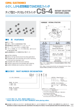
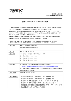
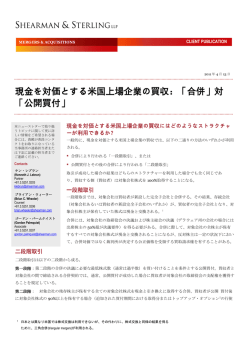
内部構造図 INTERNAL STRUCTURE
①
②
③
④
⑤
⑥
⑦
■特 長 FEATURES
ORoHS 指令対応
O小型チップ型のため高密度実装が可能
O自動搭載対応(端子形状 J- リード、ガル・ウィング)
Oフロー、リフローはんだ付けによる実装が可能
O“O”
リング採用により、ゴミ、ホコリの侵入防止、並びにはんだ
付け後の洗浄が可能
O貴金属摺動接点により接触安定性が優れている
O RoHS compliant
O Optimum for high density board mounting applications
O Compatible with most automatic pick & place machinery
(J-hook and Gull wing types only)
O Compatible with reflow and wave soldering
O Protection against dust and washable after soldering
O Excellent reliability due to precious metal contact
名 称
材 料
Part name
Material
①
ロータ
②
カバー
③
Rotor
Cover
“O” リング
“O” ring
④
固定接点
⑤
端子
⑥
ハウジング
⑦
可動接点
Fixed contact
燃焼性
Flammability
PPS(ポリフェニレンサルファイド)
Polyphenylenesulphide
UL94V-0
ステンレス
Stainless steel (SUS 304)
シリコンゴム Silicone rubber
UL94HB
銅合金、金めっき
Copper alloy, Gold-plated
Terminal pin
Housing
Slider contact
エポキシ Epoxy
UL94V-0
※ LCP
(液晶ポリマー LC polymer)
多元合金材
Multi metal alloy
※:1 回路 4 接点のみ 1 pole 4 contacts only
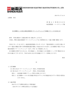
■型式表示 PART NUMBER DESIGNATION
CS-4 - 1 3 N T A
シリーズ名 Series name
端子形状 Shape of terminal
A:J- リード
J-hook
B:ガル・ウィング
Gull wing
C:スルーホールピン Through hole pins
回路数 No. of poles
包装形態 Form of packaging
1:1 回路 1 pole
2:2 回路 2 poles
接点数 No. of contacts
2:2 接点 2 contacts
3:3 接点 3 contacts
4:4 接点 4 contacts
T:テーピング(リール) Taping (Reel)
空欄:ポリ袋
Bulk in plastic bag
Blank
接点タイミング Contact timing
N:ノンショーティング(1 回路 3, 4 接点のみ)
Non-shorting (1 pole 3, 4 contacts only)
Y:ノンショーティング中立付き(1 回路 2 接点、2 回路 2 接点)
Non-shorting with neutral detent
(1pole 2 contacts, 2 poles 2 contacts)
X:ノンショーティング中立無し(1 回路 2 接点のみ)
Non-shorting without neutral detent (1 pole 2 contacts only)
※ご注文に際しては、型式一覧表をご確認ください。
Please refer to the LIST OF PART NUMBERS when placing orders.
CS-4
ROTARY SELECTOR SWITCHES (SMD)
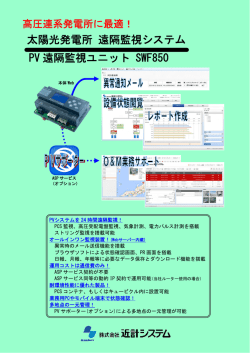
■回路図 SCHEMATICS DIAGRAMS
O1 回路 2 接点 1 pole 2 contacts
O1 回路 3 接点 1 pole 3 contacts
型式名
スイッチ特性
回路図
型式名
スイッチ特性
回路図
Series
Switching specifications
Schematic
Series
Switching specifications
Schematic
C
C
CS-4-12YA
C
1
ON
〃 YTA
2
1
1
C
CS-4-13NA
C
C
ON
1
2
3
〃 NTA
C
〃 YB
OFF
2
ON
〃 NB
〃 YTB
C
〃 YC
2
1
2
C
〃 XTA
〃 XTB
O2 回路 2 接点 2 poles 2 contacts
1
ON
2
1
型式名
スイッチ特性
回路図
Series
Switching specifications
Schematic
2
C
〃 XC
1
ON
1
C
2
2
C
1
C
1
CS-4-22YA
スイッチ特性
回路図
Series
Switching specifications
Schematic
3
〃 YTB
1
1
C
2
C
2
2
ON
2
2
1
ON
2
C
〃 NB
2
OFF
C
C
〃 NTA
C
〃 YB
ON
4
1
1
1
C
CS-4-14NA
C
〃 YTA
型式名
C
ON
2
O1 回路 4 接点 1 pole 4 contacts
NC
3
C
C
〃 XB
2
ON
ON
CS-4-12XA
1
3
C
〃 NTB
C
3
4
ON
〃 NTB
C
3
4
ON
■型式一覧表 LIST OF PART NUMBERS
回路構成
包装形態
Circuit type
Form of packaging
中立付き
テーピング
1 回路
2 接点
With neutral detent ポリ袋
1 pole
2 contacts
Without neutral detent ポリ袋
中立無し
テーピング
1 回路 3 接点
テーピング
1 pole 3 contacts
ポリ袋
1 回路 4 接点
テーピング
1 pole 4 contacts
ポリ袋
2 回路 2 接点
テーピング
2 poles 2 contacts
ポリ袋
Taping
Plastic bag
Taping
Plastic bag
Taping
Plastic bag
Taping
Plastic bag
Taping
Plastic bag
A(J- リード)
J-hook
CS-4-12YTA
CS-4-12YA
CS-4-12XTA
CS-4-12XA
CS-4-13NTA
CS-4-13NA
CS-4-14NTA
CS-4-14NA
CS-4-22YTA
CS-4-22YA
:製作不可能
※ご注文に際しては、上記型式をご確認ください。
テーピング仕様は、切り売り致しませんので、リール単位でご注文
をお願い致します。
B(ガル・ウィング) C(スルーホールピン)
包装数量
Gull wing
Through hole pin
Pieces in package
CS-4-12YTB
CS-4-12YB
CS-4-12XTB
CS-4-12XB
CS-4-13NTB
CS-4-13NB
CS-4-14NTB
CS-4-14NB
CS-4-22YTB
CS-4-22YB
CS-4-12YC
CS-4-12XC
: Not manufactured
※ Verify the above part numbers when placing orders.
Taping version can be supplied only in reel unit.
500 pcs. /reel
50 pcs./pack
500 pcs./reel
50 pcs./pack
500 pcs./reel
50 pcs./pack
500 pcs./reel
50 pcs./pack
500 pcs./reel
50 pcs./pack
CS-4
ROTARY SELECTOR SWITCHES (SMD)
■標準仕様
■電気的特性
STANDARD SPECIFICATIONS
回路構成
Circuit type
使用温度範囲
Operating temperature range
保存温度範囲
Storage temperature range
1 pole 2 contacts
1 pole 3 contacts
1 pole 4 contacts
ELECTRICAL CHARACTERISTICS
接点定格
2 poles 2 contacts
0.5 VA
Contact rating
最大電流
100 mA
Maximum current
− 25 ~ 70 °C
最小電流
− 40 ~ 70 °C
最大電圧
1 μA
Minimum current
16 V
Maximum voltage
最小電圧
シール性
Sealing
質 量
Net weight
洗浄可能 Washable by “O” ring
20 mV
Minimum voltage
※詳細は150、151 ページをご覧下さい。
※ Please refer to page 150, 151
接点タイミング
Non-shorting
Contact timing
接触抵抗
Approx. 0.08 g (CS-4-12, CS-4-13)
Approx. 0.1 g (CS-4-14, CS-4-22)
100 mΩ maximum
Contact resistance
絶縁抵抗
100 MΩ (DC500 V) minimum
Insulation resistance
耐電圧
■機械的特性
AC500 V, 60 s
Dielectric strength
MECHANICAL CHARACTERISTICS
ポジション数
No. of positions
回転トルク
Adjustment torque
回転止強度
Stopper strength
ステップ角度
Stepping angle
はんだ付け性
Solderability
■環境特性
2, 3, 4
ENVIRONMENTAL CHARACTERISTICS
10 mN·m {102 gf·cm} maximum
25 mN·m {255 gf·cm} minimum
耐衝撃性
245 ± 3 °C, 2 ~ 3 s
Shock
耐久性
固着性
Shear (Adhesion)
耐基板曲げ性
Substrate bending
引きはがし強さ
Pull-off strength
Load life
耐湿性(定常状態)
40 °C, 相対湿度 Relative humidity 90 ~ 95 %, 48 h
Humidity (Steady state)
耐熱性
70 °C, 16 h
High temperature exposure
耐寒性
Flow : 260 ± 3 °C as the temperature
in a pot of molten solder,
immersion from head of terminal to backside of board,
5 ~ 6 s, two times maximum
Reflow : Peak temperature 255 °C
(Please refer to the profile below.)
Manual soldering:350 ± 10 °C, 3 ~ 4 s
−40 °C, 16 h
Low temperature exposure
温度サイクル
Thermal shock
− 40 (0.5 h) ~ 70 °C (0.5 h), 5 cycles
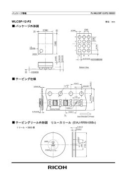
〈はんだ耐熱性評価用リフロープロファイル
Reflow profile for soldering heat evaluation〉
5 N {0.51 kgf}, 10 s
(°C)
250
Width 90 mm, bend 3 mm, 5 s, 1 time
{ } : 参考値 Reference only
Peak : 250
+5
0
°C
Over 230 °C
5 N {0.51 kgf}, 10 s
Temperature
Soldering heat
10-500-10 Hz,
3 directions for 2 h each
490 m/s2, 11 ms
6 directions for 3 times each
200 cycles minimum
DC16 V, 30 mA
Vibration
45°
90° (CS-4-12X only)
フロー:260 ± 3 °Cの槽内に端子
先端から基板の裏面まで
5∼6秒間浸漬を2回
リフロー:ピーク温度 255 °C
(詳細は下記プロファイル参照)
手はんだ:350 ± 10 °C, 3 ~ 4 s
はんだ耐熱性
振幅 (Amplitude) 1.5 mm
(全振幅)
or
加速度 (Acceleration) 98 m/s2,
耐振性
200
150
100
50
180 °C
150 °C
Pre Heating Zone
90 ± 30 s
30 ± 10 s
Heating time
Soldering Zone
リフロー回数:2回 Reflow : two times maximum
CS-4
ROTARY SELECTOR SWITCHES (SMD)
■外形寸法図 OUTLINE DIMENSIONS
2.3
1
2.35
製造年月記号
Production date code
1
2.3
2.54
4±1
2.35
0.6 W × 2.3 L × 0.5 D
0.35 min.
2.3
0.35 min.
2 – 0.8
t = 0.15
5.08
1
OCS-4-13NA
2
4±1
2.54
OCS-4-13NB
0.6 W × 2.3 L × 0.5 D
2.3
4.5
3
5.2 – 00.5
4.5
2 3
1.3
製造年月記号
Production date code
3 – 0.5
t = 0.15
1.3
1 2 3
5
2.3
1.3
3 – 0.5
t = 0.15
1.3
OCS-4-14NB
0.6 W × 2.3 L × 0.5 D
0.35 min.
OCS-4-14NA
1.2
6.2
C
C
0.35 min.
0.6 W × 2.3 L × 0.5 D
1.2
製造年月記号
Production date code
5
2.3
5
2.35
0.35 min.
5
3 – 0.6
t = 0.15
製造年月記号
Production date code
C
6.2
4.5
1.2
4.5
製造年月記号
Production date code
2
0.6 W × 2.3 L × 0.5 D
6 – 0.5
t = 0.15
NC C 1
4 3 2
2.3
1.3
1.3
5
稼働範囲 135°
Moving range
2.3
0.35 min.
ステップ角度
3 – 45°
Step angle
4 3 2
稼働範囲 135°
Moving range
6 – 0.5
t = 0.15
Production date code
4.5
3
4.5
5.2– 00.5
Production date code
製造年月記号
6.2
製造年月記号
ステップ角度
3 – 45°
Step angle
5
3
2.3
OCS-4-12XC
0.6 W × 2.3 L × 0.5 D
NC C 1
2 – 0.8
t = 0.15
2
5
OCS-4-12XB
1
5.2 – 00.5
4.5
5.08
4.5
2
5
1.2
C
C
1
2 – 0.8
t = 0.15
2.35
0.6 W × 2.3 L × 0.5 D
3 – 0.6
t = 0.15
製造年月記号
Production date code
C
2.3
OCS-4-12XA
0.6 W × 2.3 L × 0.5 D
1
2
5
OCS-4-12YC
1.2
6.2
4.5
3
5.2 – 00.5
2 – 0.8
t = 0.15
2
5
製造年月記号
Production date code
C
4.5
1
0.35 min.
0.6 W × 2.3 L × 0.5 D
1.2
製造年月記号
Production date code
C
(Unit: mm)
OCS-4-12YB
0.6 W × 2.3 L × 0.5 D
0.35 min.
OCS-4-12YA
Unless otherwise specified, tolerance: ± 0.3
1.3
1.3
CS-4
ROTARY SELECTOR SWITCHES (SMD)
■外形寸法図 OUTLINE DIMENSIONS
2
3
4.5
2
5
2.3
1.3
1.3
製造年月記号
Production date code
6 – 0.5
t = 0.15
6.2
1
1 C
4.5
2 C
製造年月記号
Production date code
5.2– 00.5
2
6 – 0.5
t = 0.15
0.35 min.
0.6 W × 2.3 L × 0.5 D
0.6 W × 2.3 L × 0.5 D
1 C
(Unit: mm)
OCS-4-22YB
C 1
5
2.3
0.35 min.
OCS-4-22YA
Unless otherwise specified, tolerance: ± 0.3
1.3
1.3
■推奨ランドパターン RECOMMENDED P.C.B. PAD OUTLINE DIMENSIONS
2
OCS-4-12YA
OCS-4-12XA
(Unit: mm)
OCS-4-12YB
OCS-4-12XB
2
0
2
2
0
4
2
2
2
1.6
1.6
2.35
1.3
1.5
0.6
1.3
0
1.3
1.5
5
0.6
1.5
1.3
1.3
OCS-4-14NB
OCS-4-22YB
3
0.6
1.5
0
0
1.5
1.3
OCS-4-14NA
OCS-4-22YA
2
OCS-4-13NB
1.5
1.5
0.6
1.5
0
2.35
3
2
OCS-4-13NA
1.6
5
1.6
1.3
1.3
注)0点は搭載中心とする
Note) The zero point is the center of mounting.
CS-4
ROTARY SELECTOR SWITCHES (SMD)
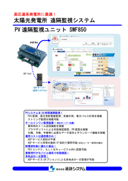
■はんだ条件
■ SOLDERING CONDITIONS
CS-4-13NA、NB、CS-22YA、YB につきましては、フローはん
When dip-soldering CS-4-13NA, NB or CS-4-22YA, YB,
solder bridges may occur between terminals depending
upon soldering conditions.
In order to prevent such bridges,vertical flow direction is
recommended as shown in the below figure.
For dip-soldering,preheating should be done after applying flux.
Handle carefully in case of parallel flow direction in which
solder bridges occur more often because solder flow
moves toward the vertical direction against the terminals.
In addition, other soldering conditions such as soldering
temperature, preheating temperature, specific gravity of
flux, and belt speed affect the occurrence of bridges.
Depending on flux to be applied, markings may, though at
rare case, disappear or fade out at soldering. Please make
sure before its use.
だ付けによる実装を行う場合、はんだ付けの条件により端子
間はんだブリッジの発生する可能性があります。
そこでブリッジ発生を軽減する為、流動方向について表に示します
が、はんだブリッジの発生しにくい直角方向にて流動することをお薦
め致します。
尚、フローはんだ付けにより実装を行う場合はフラックス塗布後、
必ず予備加熱を行ってください。
また、平行方向はハウジングの影となり、はんだブリッジが発生し
やすくなりますのでご使用の際は注意してください。
更に、はんだ温度・プレヒー
ト温度・フラックス比重・ベルトスピード等
のはんだ付け条件もブリッジの発生に影響しますので、CS-4をご検
討の際は、実際にご使用になるはんだ付け装置にて、はんだ付けの
条件を確認して頂けますようお願い致します。
また、
フラックスによっては、はんだ付け時に、マーキングが消えたり、
かすれたりする事がありますので、はんだ付け条件と合わせてご確
認願います。
流動方向
Flow direction
CS-4-13NA, NB
CS-4-22YA, YB
P.C.B.
P.C.B.
直角
Vertical
Solder
bath
平行
Parallel
Solder
bath
CS-4
ROTARY SELECTOR SWITCHES (SMD)
■ PACKAGING SPECIFICATIONS
■包装仕様
<Taping packaging specifications>
〈テーピングの包装仕様〉
O テーピングは 500 個 /リール単位の包装になりますので、500
OTaping version is packaged in 500 pcs. per reel.
Orders will be accepted for units of 500 pcs., i.e., 500,
1000, 1500 pcs., etc.
O Taping version is boxed with 4 reels (2000 pcs.).
個単位
(500 個、1000 個、1500 個…)
でのご注文をお願い致
します。
O テーピングリールの箱詰めは、4リール
(2000 個)
ごとに製品箱に
包装致します。
Maximum number of consecutive missing pieces=2
Leader length and reel dimension are shown in the diagrams below:
製品の脱落は、連続 2 個以内と致します。
テープのリーダ部、空部およびリール寸法は図に示します。
Oテープのリーダ部および空部 Embossed tape dimensions
Oリールの寸法図 Reel dimensions
(Unit: mm)
(JIS C 0806-3 に一致 Conforms to JIS C 0806-3)
(EIAJ ET-7200A に準拠 In accordance with EIAJ ET-7200A)
空部
Empty
製品装着部
Filled
空部
Empty
13
φ 21±0.8
終り
End
2±0.5
引き出し方向
Direction of feed
φ 60 +10
始め
Head
40 mm min.
20 pitches min.
リーダ部 Leader
400 mm min.
φ 13±0.2
0
φ 180 –1.5
OCS-4- □□□ TA/CS-4- □□□ TB
15.4±1
(JIS C 0806 に一致 Conforms to JIS C 0806)
(Unit: mm)
8±0.1
4±0.1
2±0.05
1.75±0.1
φ 1.5 +0.1
0
+1
0
0.3±0.1
装着例 (CS-4A)
12
5.5±0.05
Installation example
2.7
引き出し方向
Direction of feed
〈ポリ袋の包装仕様〉
O ポリ袋での最小包装は、10 個 / 袋となりますので、10 個単位
(10 個、20 個、30 個…)
でのご注文をお願い致します。
O ポリ袋の箱詰めは、50 個以上(標準は 500 個)
を製品箱に
包装致します。
<Bulk pack specifications>
OThe smallest unit of bulk pack in a plastic bag is 10 pcs.
per pack. Orders will be accepted for unit of minimum 10
pcs., i.e., 10, 20, 30 pcs. , etc.
O Boxing of bulk in a plastic bag is performed with 50 pcs.
(standard 500 pcs.) per box.
© Copyright 2026 Paperzz