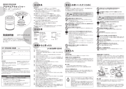
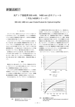
SIGNAL PROCESSING UNIT PFV-SP3100 電気製品は、安全のための注意事項を守らないと、 火災や人身事故になることがあります。 このオペレーションマニュアルには、事故を防ぐための重要な注意事項と 製品の取り扱いかたを示してあります。このオペレーションマニュアルを よくお読みのうえ、製品を安全にお使いください。お読みになったあと は、いつでも見られるところに必ず保管してください。 OPERATION MANUAL 1st Edition [Japanese/English] 安全のために ソニー製品は安全に十分に配慮して設計されています。 しかし電気製品は、安全 のための注意事項を守らないと、火災や感電などにより死亡や大けがなど人身事 故につながることがあり、危険です。 事故を防ぐために次のことを必ずお守りください。 安全のための注意事項を守る 警告表示の意味 このオペレーションマニュアル および製品では、次のような表 示をしています。表示の内容を よく理解してから本文をお読み ください。 2(J)〜 3(J)ページの注意事項をよくお読みください。 オプションユニットの装着について 危険を避けるために、オプションユニットの装着はサービストレーニングを受けた技 術者、もしくはソニーのサービス担当者または営業担当者にご依頼ください。 この表示の注意事項を守らない と、火災や感電などにより死亡 や大けがなど人身事故につなが ることがあります。 定期点検を実施する 長期間安全に使用していただくために、定期点検を実施することをおすすめしま す。点検の内容や費用については、ソニーのサービス担当者または営業担当者 にご相談ください。 この表示の注意事項を守らない と、感電やその他の事故により けがをしたり周辺の物品に損害 を与えたりすることがあります。 故障したら使用を中止する ソニーのサービス担当者、または営業担当者にご連絡ください。 注意を促す記号 万一、異常が起きたら 異常な音、に おい、煙が出 たら 炎が出たら , 1 電源を切る。 2 電源コードや接続コードを抜く。 3 ソニーのサービス担当者、または営業担当者に 修理を依頼する。 行為を禁止する記号 , すぐに電源を切り、消火する。 行為を指示する記号 目次 警告 ................................................................................................................... 2(J) 注意 ................................................................................................................... 3(J) 概要 ......................................................................................................................... 4(J) 特長 .................................................................................................................................. 4(J) 別売り基板 ...................................................................................................................... 4(J) 別売りアクセサリー ...................................................................................................... 4(J) 各部の名称と働き .................................................................................................... 5(J) 仕様 ......................................................................................................................... 6(J) 1 (J) 日 本 語 下記の注意を守らないと、 火災や感電により死亡や大けがにつながることがあります。 外装を外さない、改造しない 外装を外したり、改造したりすると、感電の原因となります。 内部の調整や設定および点検を行う必要がある場合は、必ずサービストレーニン グを受けた技術者にご依頼ください。 内部に水や異物を入れない 水や異物が入ると火災や感電の原因となります。 万一、水や異物が入ったときは、すぐに電源を切り、電源コードや接続コードを抜 いて、ソニーのサービス担当者または営業担当者にご相談ください。 指定の電源コードを使用する 指定以外の電源コードを使用すると、火災や感電の原因となります。 他の電源コードを使用する場合は、 ソニーのサービス担当者または営業担当者に ご相談ください。 電源コードを傷つけない 電源コードを傷つけると、火災や感電の原因となります。 • 電源コードを加工したり、傷つけたりしない。 • 重いものをのせたり、引っ張ったりしない。 • 熱器具に近づけたり、加熱したりしない。 • 電源コードを抜くときは、必ずプラグを持って抜く。 • ラックマウントするとき、レールにはさみ込まない。 万一、電源コードが傷んだら、ソニーのサービス担当者に交換をご依頼ください。 油煙、湯気、湿気、ほこりの多い場所では設置•使用しない 上記のような場所で設置・使用すると、火災や感電の原因となります。 ファンが止まったままの状態で使用しない ファンが止まると、ステータス表示ランプが赤く点滅します。そのまま使用し続ける と、内部に熱がこもり火災の原因となることがあります。ソニーのサービス担当者 または営業担当者にご連絡ください。 電源コードのプラグおよびコネクターは突き当たるまで差し込 む 電源プラグがACインレットに不完全にささっていると、発火や発熱の原因となりま す。 2 (J) 下記の注意を守らないと、 けがをしたり周辺の物品に損害を与えることがあります。 通風孔をふさがない 通風孔をふさぐと内部に熱がこもり、火災や故障の原因となることがあります。風 通しをよくするために次の項目をお守りください。 • 壁から10 cm 以上離して設置する。 • 密閉された狭い場所に押し込めない。 • 毛足の長い敷物(じゅうたん・布団など)の上に設置しない。 • 布などで包まない。 • あお向けや横倒し、逆さまにしない。 安定した場所に設置する ぐらついた台の上や傾いたところなどに設置すると、製品が落下してけがの原因 となることがあります。 安全アースを接続する 安全アースを接続しないと、感電の原因となることがあります。次の方法でアース を接続してください。 • 電源コンセントが 3 極の場合 別売りの電源コードセット (1-791-041-31)を使用することで安全アースが接続さ れます。 • 電源コンセントが 2 極の場合 別売りの3極→ 2極変換プラグ(1-793-461-11)を使用し、変換プラグから出て いる緑色のアース線を建物に備えられているアース端子に接続してください。 変換プラグ アース線 安全アースを取り付けることができない場合は、 ソニーのサービス担当者または営 業担当者にご相談ください。 3 (J) 概要 シグナルプロセッシングユニットPFV-SP3100は、 ビデオ/オーディ 別売り基板 オ信号を扱う機器間のインターフェースおよび信号処理を行うため のユニットです。 PFV-SP3100 の別売り基板として、HKPF-SP/HKSPシリーズ基板 本体は、電源部、マザーボード、4個のオプション基板用スロットで をラインナップしています。使用の目的に合わせて必要な基板を選 構成されています。 択し、本機に装着します。 これらのスロットにオプション基板を装着することで、本機から基板 に電源が供給され、基板の機能が動作します。 別売りのオプショ HKPF-SP/HKSPシリーズ基板例 ン基板群の中からシステムの目的に合わせて基板を選択して本機 に装着することにより、 1台のPFV-SP3100 で各種の処理を行う柔 軟性に富んだシステム設計が可能となります。 特長 基板名 機能 HKPF-SP003 デジタルディストリビューションアンプ HKPF-SP021 O/Eコンバーター HKPF-SP022 E/Oコンバーター HKSP-008HD HDフレーム/ラインシンクロナイザー HKSP-061M 8 × 4 デジタルビデオセレクター 独立機能の基板による多様な処理への対応 HKSP-105 HD オーディオ/ビデオ マルチプレクサー 別売りの基板により、様々なインターフェース機能を 1 台の PFV- HKSP-106 HD オーディオ/ビデオ デマルチプレクサー SP3100で構成することができます。最大4枚の基板を装着できま HKSP-300 プロセッシングモジュールコントローラー す。 HKSP-313 HDカラーコレクター HKSP-525 ダウンコンバーター 2電源ブロックの使用による高信頼性 HKSP-1125 HDアップコンバーター 別売りのバックアップパワーサプライユニットHK-PSU01を装着する HKSP-R80 ルーティングスイッチャーコントローラー と、2 系統の電源供給が可能になります。 片方の電源が停止しても、もう一方からの電源供給が行われる、 信頼性の高い設計です。 ご注意 (HKSP-300/R80 のみ) LANケーブルを使用するときは、安全のため、この端子を過大電 圧がかかる可能性のある周辺機器接続用コネクターには接続しな ラックマウント いでください。 EIA の19インチラックにマウントできるサイズになっています。 ラックマウント時には、ラックマウントキットRMM-10を取り付ける構 造になっています。RMM-10を装着する場合は、ソニーのサービ 別売りアクセサリー ス担当者にご依頼ください。 HK-PSU01 バックアップパワーサプライユニット RMM-10 ラックマウントキット 4 (J) 各部の名称と働き 前面 1 ステータス表示ランプA、B SIGNAL PROCESSING UNIT O I O POWER A PFV-SP3100 I POWER B 3 POWERスイッチB 2 POWERスイッチA 後面 4 REF IN端子 5 STATUS OUT端子 6 REMOTE端子 STATUS OUT B REMOTE U A -AC IN REF IN A REF IN B 0 U(信号用アース)端子 7 ブランクパネル 9 〜AC IN端子A 8 〜AC IN端子B 1 ステータス表示ランプA、B 各2個の端子は内部でスルー接続されています。スルーアウト信号 それぞれ電源ユニットA(標準装備)または電源ユニットB(オプ を使用しないときは、使用しない端子に市販の75Ω終端器を接続 ション)の電源が入ると緑色に点灯します。 して終端してください。 ユニット内の状態により、以下のように表示します。 緑点滅 • オプション基板でワーニングが発生した 赤点灯 • 電源ユニットの換気用ファンが停止した • 電源ユニットで異常が生じた 赤点滅 5 STATUS OUT(ステータス出力)端子(ミニD-sub 15 ピン) 前面のステータス表示ランプと同様に本機の状態を出力します。 ◆詳しくは、インストレーションマニュアルをご覧ください。 6 REMOTE(リモート)端子(BNC型) ルーティングスイッチャーの制御等に用いられるS-BUS端子です。 • オプション基板でエラーが発生した 本機に装着した基板が、PFV-SP3100本体へのS-BUS通信を必要 • オプション基板の消費電流が規定以上に大きい とする場合、この端子に S-BUS 制御線を接続します。 • このユニットの換気用ファンが停止した 消灯 7 ブランクパネル • 電源ユニットの電源スイッチをOFFにした 基板を取り付けるときははずします。 • 電源ユニットの出力電圧に異常が発生した 8 -AC IN(AC電源入力)端子B 2 POWER(電源)スイッチA 電源ユニットB の AC 電源入力端子です。 電源ユニットA(標準装備)の電源をON/OFFします。 推奨の電源コードを使ってAC 電源を接続します。 3 POWER(電源)スイッチB 9 -AC IN(AC電源入力)端子A 電源ユニットB(オプション)の電源をON/OFFします。 電源ユニットA の AC 電源入力端子です。 推奨の電源コードを使ってAC 電源を接続します。 4 REF IN(同期信号入力)端子(BNC型) A、Bの2系統のアナログのリファレンスビデオ信号 (ブラックバース 0 U(信号用アース)端子 ト信号または HDTV 用 3 値シンク信号)を入力します。 必要に応じて接地してください。 5 (J) 仕様 電源電圧 AC 100 – 240 V、50/60 Hz 消費電流 AC 100 V:1 A AC 240 V:0.5 A 供給可能電力 + 12 使用温度 +5 V DC:最大 4.4 A 性能保証温度 + 10 保存温度 − 20℃〜+ 60℃ 湿度 10〜 90%(結露なし) 最大外形寸法 440 × 43.6 × 550 mm(幅 / 高さ/ 奥行き) 重量 約 8.5 kg(別売り基板含まず) ℃〜+ 40℃ ℃〜+ 35℃ 入力端子 リモート S-BUS リモート端子:BNC 型(1) 同期入力 HD3 値シンク/ブラックバースト: BNC 型、2 系統(ループスルー出力付き) ステータス出力 付属品 STATUS OUT:ミニ D-sub 15ピン、メス(1) オペレーションマニュアル(1) インストレーションマニュアル(1) 本機は「高調波ガイドライン」適合品です。 この装置は、情報処理装置等電波障害自主規制協議会 (VCCI)の基準に基づくクラスA情報技術装置です。この装置 を家庭環境で使用すると電波妨害を引き起こすことがあります。 この場合には使用者が適切な対策を講ずるよう要求されること があります。 仕様および外観は、改良のため予告なく変更することがあります が、ご了承ください。 6 (J) English THIS APPARATUS MUST BE EARTHED. AVERTISSEMENT Afin d’éviter tout risque d’incendie ou d’électrocution, ne pas exposer cet appareil à la pluie ou à l’humidité. Afin d’écarter tout risque d’électrocution, garder le coffret fermé. Ne confier l’entretien de l’appareil qu’à un personnel qualifié. CET APPAREIL DOIT ÊTRE RELIÉ À LA TERRE. WARNUNG Um Feuergefahr und die Gefahr eines elektrischen Schlages zu vermeiden, darf das Gerät weder Regen noch Feuchtigkeit ausgesetzt werden. Um einen elektrischen Schlag zu vermeiden, darf das Gehäuse nicht geöffnet werden. Überlassen Sie Wartungsarbeiten stets nur qualifiziertem Fachpersonal. DIESES GERÄT MUSS GEERDET WERDEN. This symbol is intended to alert the user to the presence of important operating and maintenance (servicing) instructions in the literature accompanying the appliance. WARNING: THIS WARNING IS APPLICABLE FOR USA ONLY. If used in USA, use the UL LISTED power cord specified below. DO NOT USE ANY OTHER POWER CORD. Plug Cap Cord Length Rating Parallel blade with ground pin (NEMA 5-15P Configuration) Type SJT, three 16 or 18 AWG wires Less than 2.5 m (8 ft. 3 in.) Minimum 10 A, 125 V Using this unit at a voltage other than 120 V may require the use of a different line cord or attachment plug, or both. To reduce the risk of fire or electric shock, refer servicing to qualified service personnel. WARNING: THIS WARNING IS APPLICABLE FOR OTHER COUNTRIES. 1. Use the approved Power Cord (3-core mains lead)/ Appliance Connector/Plug with earthing-contacts that conforms to the safety regulations of each country if applicable. 2. Use the Power Cord (3-core mains lead)/Appliance Connector/Plug conforming to the proper ratings (voltage, ampere). If you have questions on the use of the above Power Cord/ Appliance Connector/Plug, please consult a qualified service personnel. For the customers in the USA This equipment has been tested and found to comply with the limits for a Class A digital device, pursuant to Part 15 of the FCC Rules. These limits are designed to provide reasonable protection against harmful interference when the equipment is operated in a commercial environment. This equipment generates, uses, and can radiate radio frequency energy and, if not installed and used in accordance with the instruction manual, may cause harmful interference to radio communications. Operation of this equipment in a residential area is likely to cause harmful interference in which case the user will be required to correct the interference at his own expense. You are cautioned that any changes or modifications not expressly approved in this manual could void your authority to operate this equipment. The shielded interface cable recommended in this manual must be used with this equipment in order to comply with the limits for a digital device pursuant to Subpart B of Part 15 of FCC Rules. For the customers in Europe This product with the CE marking complies with both the EMC Directive (89/336/EEC) and the Low Voltage Directive (73/23/EEC) issued by the Commission of the European Community. Compliance with these directives implies conformity to the following European standards: • EN60950: Product Safety • EN55103-1: Electromagnetic Interference (Emission) • EN55103-2: Electromagnetic Susceptibility (Immunity) This product is intended for use in the following Electromagnetic Environment(s): E1 (residential), E2 (commercial and light industrial), E3 (urban outdoors) and E4 (controlled EMC environment, ex. TV studio) Pour les clients européens Ce produit portant la marque CE est conforme à la fois à la Directive sur la compatibilité électromagnétique (EMC) (89/ 336/CEE) et à la Directive sur les basses tensions (73/23/ CEE) émises par la Commission de la Communauté Européenne. La conformité à ces directives implique la conformité aux normes européennes suivantes: • EN60950: Sécurité des produits • EN55103-1: Interférences électromagnétiques (émission) • EN55103-2: Sensibilité électromagétique (immunité) Ce produit est prévu pour être utillisé dans les environnements électromagnétiques suivants: E1 (résidentiel), E2 (commercial et industrie légère), E3 (urbain extérieur) et E4 (environnement EMC contrôlé ex. studio de télévision). Für Kunden in Europa Dieses Produkt besitzt die CE-Kennzeichnung und erfüllt sowohl die EMV-Direktive (89/336/EEC) als auch die Direktive Niederspannung (73/23/EEC) der EG-Kommission. Die Erfüllung dieser Direktiven bedeutet Konformität für die folgenden Europäischen Normen: • EN60950: Produktsicherheit • EN55103-1: Elektromagnetische Interferenz (Emission) • EN55103-2: Elektromagnetische Empfindlichkeit (Immunität) Dieses Produkt ist für den Einsatz unter folgenden elektromagnetischen Bedingungen ausgelegt: E1 (Wohnbereich), E2 (kommerzieller und in beschränktem Maße industrieller Bereich), E3 (Stadtbereich im Freien) und E4 (kontrollierter EMV-Bereich, z.B. Fernsehstudio) 1(E) English WARNING To prevent fire or shock hazard, do not expose the unit to rain or moisture. To avoid electrical shock, do not open the cabinet. Refer servicing to qualified personnel only. Table of Contents Overview ............................................................................................... 3(E) Features .......................................................................................... 3(E) Optional Boards .............................................................................. 3(E) Optional Accessories ...................................................................... 3(E) Locations and Functions of Parts ....................................................... 4(E) Specifications ........................................................................................ 6(E) 2(E) Overview The PFV-SP3100 Signal Processing Unit is an apparatus for interfacing various kinds of equipment to process video and audio signals. The unit is composed of a power block, a main board and 4 slots to accommodate optional boards. When an optional board is installed in one of the slots, the power is supplied from the PFV-SP3100 to the board, and the functions of the board are activated. Select the appropriate optional boards and install them into the PFV-SP3100, allowing the unit to execute various signal-processing functions. Features Various kinds of signal processing with optional boards With the appropriate optional boards installed, various functions regarding serial digital video signals can be processed in a single PFV-SP3100 unit. Up to 4 boards can be installed in combination in the PFV-SP3100. Reliable operation assured by two AC lines and optional backup power supply unit Attaching the optional HK-PSU01 Backup Power Supply Unit enables the PFV-SP3100 to be supplied with power from two separate lines. If one of the power blocks stops supplying power, the other block will supply full power. Thus, highly reliable operation is maintained. Optional Boards The HKPF-SP/HKSP-series boards are provided as optional boards for the PFV-SP3100. Select boards with the required functions, and install them in slots of the PFV-SP3100. Some of HKPF-SP/HKSP-series boards Board name Functions HKPF-SP003 Digital distribution amplifier HKPF-SP021 O/E converter HKPF-SP022 E/O converter HKSP-008HD HD frame/line synchronizer HKSP-061M 8×4 digital video selector HKSP-105 HD audio/video multiplexer HKSP-106 HD audio/video de-multiplexer HKSP-300 Processing Module Controller HKSP-313 HD color corrector HKSP-525 Down-converter HKSP-1125 HD up-converter HKSP-R80 Routing switcher controller Caution (HKSP-300/R80 only) When using a LAN cable: For safety, do not connect to a connector for peripheral device wiring that might have excessive voltage. Optional Accessories Rack mounting The unit can be mounted in a standard 19-inch rack. To mount the unit to the rack, the RMM-10 Rack Mount Kit is necessary. For mounting the RMM-10, consult your Sony service personnel. HK-PSU01 Backup Power Supply Unit RMM-10 Rack Mount Kit 3(E) Locations and Functions of Parts Front panel 1 Status indicators A, B SIGNAL PROCESSING UNIT O I POWER A O PFV-SP3100 I POWER B 3 POWER B switch 2 POWER A switch 4 REF IN connectors Rear panel 5 STATUS OUT connector 6 REMOTE connector STATUS OUT B REMOTE U A -AC IN REF IN A REF IN B 0 U (signal ground) terminal 7 Cover plates 9 -AC IN A connector 8 -AC IN B connector 1 Status indicators A and B Indicator A and B light in green when power unit A (standard) or power unit B (optional) is turned on. They indicate the following internal statuses: Flashing in green • A warning has been generated on an optional board. Lit in red • The ventilation fan of the power unit has stopped rotating. • An abnormal condition has occurred in the power unit. Flashing in red • An error has been generated on an optional board. • The current consumption of an optional board exceeds the specified value. • The ventilation fans of this processing unit have stopped rotating. Unlit • The power switch of the power unit is turned off. • Trouble occurs with the output voltage of the power unit. 2 POWER A switch Turns on and off power unit A (standard). 4(E) 3 POWER B switch Turns on and off power unit B (optional). 4 REF IN (reference input) connectors (BNC type) The connectors accept two (A and B) analog reference video signals (black burst signals or tri-level sync signals for HDTV). Two connectors of each pair have internal loopthrough connections. If loop-through output signals are not used, put a 75-ohm terminator on any connector that is not used. 5 STATUS OUT connector (Mini D-sub 15-pin) Outputs the statuses of the unit in the same manner as the front-panel status indicators. For details, refer to the installation manual. 6 REMOTE connector (BNC type) The connector is an S-BUS connector to be used for routing switcher control. When a board installed in this unit requires S-BUS communication with the PFV-SP3100 main frame, connect an S-BUS control line to this connector. 7 Cover plates Remove the corresponding plates to install the optional boards. 8 -AC IN B connector To supply power to power unit B, connect to an AC power supply using one of the following power cords: Model available in North America: Part No. 1-557-377-11 Model available in the United Kingdom: Part No. 1-782-929-11 9 -AC IN A connector To supply power to power unit A, connect to an AC power supply using one of the following power cords: Model available in North America: Part No. 1-557-377-11 Model available in the United Kingdom: Part No. 1-782-929-11 0 U (signal ground) terminal For signal ground. Connect to a ground wire as required. 5(E) Specifications Power requirements 100 to 240 V AC, 50/60 Hz Current drain 100 V AC: 1 A 240 V AC: 0.5 A Peak inrush current (1) Power ON, current probe method: 33 A (240 V), 10 A (100 V) (2) Hot switching inrush current, measured in accordance with European standard EN55103-1: 8 A (230 V) Power supply capacity +12 V DC: max. 4.4 A Operating temperature +5°C to +40°C (+41°F to +104°F) Performance guaranteed temperature +10°C to +35°C (+50°F to +95°F) Storage temperature –20°C to +60°C (–4°F to +140°F) Operating humidity 10% to 90% (no condensation) Dimensions 440 × 43.6 × 550 mm (w/h/d) (17 3/8 × 1 3/4 × 21 3/4 inches) Mass Approx. 8.5 kg (18 lb 12 oz) (not including the optional boards) Inputs Remote S-BUS remote connector: BNC type (1) Sync input HD tri-level sync/black burst: BNC type, 2 pairs (with loopthrough outputs) Status output STATUS OUT: Mini D-sub 15-pin, female (1) Supplied accessories Operation Manual (1) Installation Manual (1) Design and specifications are subject to change without notice. 6(E) The material contained in this manual consists of information that is the property of Sony Corporation and is intended solely for use by the purchasers of the equipment described in this manual. Sony Corporation expressly prohibits the duplication of any portion of this manual or the use thereof for any purpose other than the operation or maintenance of the equipment described in this manual without the express written permission of Sony Corporation. Le matériel contenu dans ce manuel consiste en informations qui sont la propriété de Sony Corporation et sont destinées exclusivement à l’usage des acquéreurs de l’équipement décrit dans ce manuel. Sony Corporation interdit formellement la copie de quelque partie que ce soit de ce manuel ou son emploi pour tout autre but que des opérations ou entretiens de l’équipement à moins d’une permission écrite de Sony Corporation. Das in dieser Anleitung enthaltene Material besteht aus Informationen, die Eigentum der Sony Corporation sind, und ausschließlich zum Gebrauch durch den Käufer der in dieser Anleitung beschriebenen Ausrüstung bestimmt sind. Die Sony Corporation untersagt ausdrücklich die Vervielfältigung jeglicher Teile dieser Anleitung oder den Gebrauch derselben für irgendeinen anderen Zweck als die Bedienung oder Wartung der in dieser Anleitung beschriebenen Ausrüstung ohne ausdrückliche schriftliche Erlaubnis der Sony Corporation. Sony Corporation PFV-SP3100 (SY) 3-690-485-01(1) B&P Company Printed in Japan 2002.07.13 2002
© Copyright 2026 Paperzz