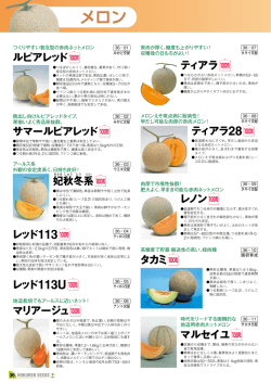
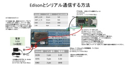
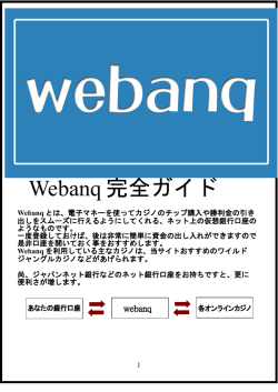
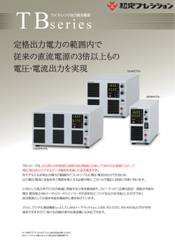
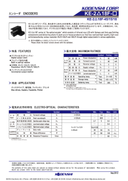
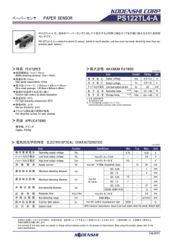
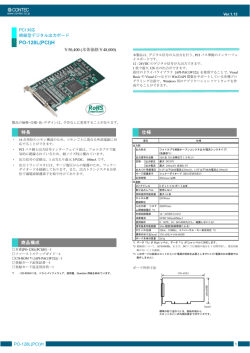
D
Digi / Con
アナログコンバータ
EX30AR Series
Analog Converter
流量計からのパルス出力信号をアナログ信号へと変換して出力します。
警報出力を2系統搭載。各種制御用に充分にお使いいただけます。
アラーム警報を2接点有し、設定値はお客様にて選択可能です。
速度、流量、
ロータリエンコーダーなどのパルス出力センサを接続する事で、
各種機械、装置の様々な監視用として自動化システムに効果を発揮します。
■
■
■
■
Pulse output signal coming from flowmeter is converted to analog signal and produces it.
As two alarm systems are loaded in the EX30AR Series Converter, it can be applied to various kinds of controls.
Since the Converter has two contacts as an alarm for warning , selection can be made by customers for your setting the
setting value.
By connecting pulse output sensor such as used in the velocity, flowrate and rotary encoder, it will work on the automation
system such as monitoring various kinds of machine and equipments.
■
■
■
■
型式
型式欄にご記入頂き、そのままFAXでもOK! お見積もり、ご注文承ります。
Type selection
規格1
Std.1
規格2
Std.2
EX30AR -
オプション
Options
-
I
V
VW
VN
VT
オプション記号 Optional Symbols *1
特殊項目
For specif item
-
SC 信号ケーブル 1m付 Signal cable 1m long attached *1
D 防滴カバー For example of entry *2
無記入 Blank 標準タイプ Std. type
パネル埋込タイプ Panel embedded type
P
4∼20mA
0∼5V
0∼10V
1∼5V
1∼10V
ARI
ARIP
ARV
ARVP
ARW
EX30AR-I
EX30AR-IP
EX30AR-V
EX30AR-VP
EX30AR-VW
ARWP
ARN
ARNP
ART
ARTP
EX30AR-VWP
EX30AR-VN
EX30AR-VNP
EX30AR-VT
EX30AR-VTP
パネル埋込タイプ
Panel embedding type
パネルマウントタイプ(標準)
Panel mounting type(Standard)
*1:標準仕様はお客様にてケーブルを用意していただきます。(ピン、
コネクタは製品に添付)
流量センサの型式末尾にオプション記号でご依頼いただいた場合、
コネクタパックではなく信号ケーブルを標準添付いたします。
*2:パネル埋込みタイプには使用できません。
*1 : Customers are requested to prepare for signal cable in standard specification. (Pin and connector are attached to product)
In a case where option code is added at the end of model number of flow sensor, signal cable is enclosed, not the connector pack.
*2 : It cannot be used for the panel-embedded type.
仕様
Specifications
項目 Items
表示
Display
入力信号
Input signal
出力信号
Output signal
電源
Power supply
環境
Environment
EX30AR
電源表示 Power supply display
電源「ON」時:緑色LED点灯 Green LED is lit , when power is ON.
比較出力表示 Integrating value
比較出力「ON」時:橙色LED点灯 Orange LED is lit, when comparative output is ON.
オーバーフロー表示 Overflow display*1
比較出力LED点滅 Comparative output LED blinks.
入力応答0∼300Hz(但しduty50%)オープンコレクタ出力の機器より駆動
パルス入力 Pulse input *2
アナログ出力 Analog output *3
Pulse input Input response 0-300Hz(50% duty) Driven by the devices with open collector output
EX30AR-V
EX30AR-I
比較動作出力 Comparative operating output *4
0∼5V、1∼5V、0∼10V、1∼10Vの何れかで出力 Output by any of them such as 0 - 5V, 1 -5V, 0 - 10V and 1 - 10V
4∼20mA出力 Output at 4-20mA
リレー出力 2点(最大負荷電圧:DC30V 最大負荷電流:100mA)
Relay output 2 points (Max.load voltage : 30VDC, Max load current: 100mA)
電圧 / 電流 voltage / current
DC24V ±10% / V : 約40mA, I : 約65mA V : Approx 40mA, I : Approx 65mA
センサ用出力電圧 / 電流 Output voltage for sensor /current
Ta=+23±5℃ : DC5V±10% / 10mA max
動作温度 Operating temperature
0∼55℃
動作相対湿度 Relative operating humidity
35∼85%RH (結露なきこと)(Non condensing)
保存温度 Storing temperature
-20∼70℃
電源標準ケーブル:9芯 2m Standard power cable(9 wires), 2m long
ケーブル Cable
:標準:コネクタパック添付 Optional cable for signal: Standard: Connector pack attached
信号オプションケーブル:SC:3芯 1m Optional cable: SC : 3 wires, 1m long
サイズ(コネクタを除く)Size (Excluding connectors)
30W×30H×26.2D(mm)
キャビネット Cabinet
プラスチックモールド製 Made by plastic mold
*1:オーバーフロー発生時は比較出力LED点滅
*2:パルス計測方式は周期測定方式となります。
*3:アナログ出力は、流量と比例した出力となります。
例): 4mA : 0L/min、20mA : Max.流量(ただし、精度保証は測定範囲内になります。)
*4:比較動作は共通技術資料をご参照ください。
252
2016 Vol.1
*1:Customers are requested to prepare for signal cable in standard specification. (Pin and connector are attached to product)
*2:Pulse measuring method is a periodic measurement.
*3:Analog output is the one proportional to the flowrate.
For example) 4mA: 0L/min, 20mA: Max flowrate (However accuracy warranty shall be within the measuring ranges.)
*4:For the comparative operation, see the common technical data.
D
表示計・変換器
外形図
Outline drawing
EX30AR EX30AR outside dimensional drawing
30
4-φ3.5
60
20
20
30
30
34 -0
+0.5
20
55
(26)
3
30
(26.2)
パネルカット For panel cut-out
アナログコンバータ
30
パネルマウント取付板 Panel mounting adapter
+0.5
34 -0
着脱スペース Detachable space:100
パネル板厚 Panel thickness:1∼3
EX30AR
配線図
取付アダプタ付属
Mounting adapter is attached.
Wiring diagram
警報出力の形態 Alarm output forms
信号名
接続ピンNo.
Names of signals Connecting pin No.
CP1
12←1
321
CN1
CN2
信号オプションケーブル(3芯、1m) AWG26
Optional cable for signal (3 wires, 1m long) AWG26
CP2
6-10
出力動作
Output operation
LED
N.O. 上限ON ON at upper limit ONで点灯 It is lit up, when turned ON.
7-10
N.C. 下限ON ON at lower limit ONで消灯 It is lit out, when turned ON.
8-10
N.O. 下限ON ON at lower limit ONで点灯 It is lit up, when turned ON.
9-10
N.C. 上限ON ON at upper limit ONで消灯 It is lit out, when turned ON.
ピンNo.1:パルス入力 Pin No.1:Pulse input
Black
黒
Blue
青
ピンNo.2:パルス信号とセンサ電源コモン Pin No.2:Pulse signal and common to sensor power supply
Brown
茶
ピンNo.3:センサ用DC+5V電源出力 Pin No.3:Power supply output at +5VDC for sensor
注:CN2の信号ケーブルは標準では付属されておりません。(ハウジングとコンタクトピンのみ付属)
Note: In case of standard spec. Signal cable for CN2 is not attached. (Only housing and contact pin are attached. )
(70)
電源標準ケーブル(9芯、2m)
AWG28
Standard power cable (9 wires, 2m long)
AWG28
アース線(緑) AWG22
Earth wire(Green) AWG22
Blue
青
ピンNo.4:アナログ出力GND Pin No.4:Analog output GND
Brown
茶
ピンNo.5:アナログ出力 Pin No.5:Analog output
Yellow
黄
ピンNo.6:比較出力CP1(N.O.) Pin No.6:Comparative output CP 1(N.O.)
Orange
橙
ピンNo.7:比較出力CP1(N.C.) Pin No.7:Comparative output CP 1(N.C.)
Green
緑
ピンNo.8:比較出力CP2(N.O.) Pin No.8:Comparative output CP2 (N.O.)
Purple
紫
ピンNo.9:比較出力CP2(N.C.) Pin No.9:Comparative output CP 2(N.C.)
White
白
ピンNo.10:CP1、CP2コモン Pin No.10:Common to CP 1 and CP 2
Black
黒
ピンNo.11:電源DC0V Pin No.11:Power supply 0VDC
Red
赤
ピンNo.12:電源DC+24V Pin No.12:Power supply +24VDC
①:アースは、第三種アース
(100Ω以下)
とします。
②:入力はシングルエンドタイプです。
③:CP1及びCP2比較出力は、
リレー出力です。
④:COMピンとGNDピンは接続されておりません。
* 添付ハウジング、
コンタクトの型式(日圧製)
CN2 ハウジング : PHR-3
コンタクト : SPH - 002T - P0.5S
① : Earth of the third class should be used for grounding (Below 100Ω).
② : Input is a single end type.
③ : The comparative outputs of CP1 and CP2 are relay output.
④ : COM pin and GND pin are not connected.
* Accompanying housing and the contact type (Made by J.S.T.)
CN2 Housing : PHR-3
Contact : SPH - 002T - P0.5S
注:CN1のピンNo.1∼3は空ポートです。 Note: Pin No. 1 to 3 in CN2 are blank port.
配線の接続方法
How to connect wires
比較出力の接続 Connecting comparative output
センサの接続 Connecting sensor
SIN 1
EX30AR(CN2)
SCOM 2
+5VOUT 3
黒 Black
青 Blue
茶 Brown
センサ Sensor
6
Output
GND
Vcc
7
EX30AR(CN1)
8
9
10
センサ電源の接続は、CN2の3番ピンと2番ピンです。電圧は5V±10%です。
電流容量は最大10mAです。10mAを超える負荷を接続しないでください。
Power supply for sensor is connected to Pin No. 3 and 2 in CN 2. The voltage is 5V±10% and current capacity
is max. 10mA. Do not connect any load exceeding 10mA.
黄 Yellow
橙 Orange
緑 Green
紫 Purple
白 White
CP1(N.O.)
CP1(N.C.)
CP2(N.O.)
CP2(N.C.)
COM
CP1の接続は、CN1の6、7番ピンと10番ピンです。CP2の接続は、CN1の
8、9番ピンと10番ピンです。比較出力に印可できる最大電圧は30Vです。
また、電流は絶対に100mAを超えない範囲でご使用ください。
CP 1 is connected to Pin No. 6, 7 and 10 in CN 1. CP 2 is connected to Pin No. 8 and 9 in CN 1. Max voltage to
be impressed to comparative output is 30V and in no event may the current exceed the 100mA.
2016 Vol.1
253
© Copyright 2026 Paperzz