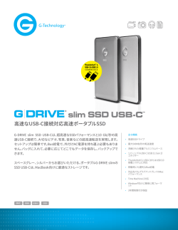
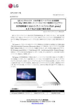
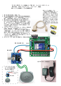
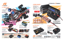
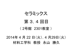
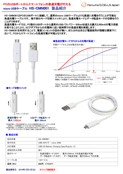
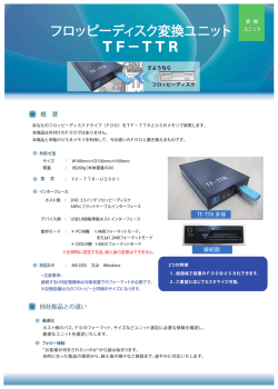
Is Now Part of
To learn more about ON Semiconductor, please visit our website at
www.onsemi.com
ON Semiconductor and the ON Semiconductor logo are trademarks of Semiconductor Components Industries, LLC dba ON Semiconductor or its subsidiaries in the United States and/or other countries. ON Semiconductor owns the rights to a number
of patents, trademarks, copyrights, trade secrets, and other intellectual property. A listing of ON Semiconductor’s product/patent coverage may be accessed at www.onsemi.com/site/pdf/Patent-Marking.pdf. ON Semiconductor reserves the right
to make changes without further notice to any products herein. ON Semiconductor makes no warranty, representation or guarantee regarding the suitability of its products for any particular purpose, nor does ON Semiconductor assume any liability
arising out of the application or use of any product or circuit, and specifically disclaims any and all liability, including without limitation special, consequential or incidental damages. Buyer is responsible for its products and applications using ON
Semiconductor products, including compliance with all laws, regulations and safety requirements or standards, regardless of any support or applications information provided by ON Semiconductor. “Typical” parameters which may be provided in ON
Semiconductor data sheets and/or specifications can and do vary in different applications and actual performance may vary over time. All operating parameters, including “Typicals” must be validated for each customer application by customer’s
technical experts. ON Semiconductor does not convey any license under its patent rights nor the rights of others. ON Semiconductor products are not designed, intended, or authorized for use as a critical component in life support systems or any FDA
Class 3 medical devices or medical devices with a same or similar classification in a foreign jurisdiction or any devices intended for implantation in the human body. Should Buyer purchase or use ON Semiconductor products for any such unintended
or unauthorized application, Buyer shall indemnify and hold ON Semiconductor and its officers, employees, subsidiaries, affiliates, and distributors harmless against all claims, costs, damages, and expenses, and reasonable attorney fees arising out
of, directly or indirectly, any claim of personal injury or death associated with such unintended or unauthorized use, even if such claim alleges that ON Semiconductor was negligent regarding the design or manufacture of the part. ON Semiconductor
is an Equal Opportunity/Affirmative Action Employer. This literature is subject to all applicable copyright laws and is not for resale in any manner.
www.fairchildsemi.com
AN-6105
USB Type-C の設計における注意点
USB Type-C アダプター
概要
詳細
USB は広く普及している接続方式で、多くのユーザー
によって様々な機器に使用されています。USB Type-C
コネクターが正式にリリースされ、多くの企業が他社
より先に、この新しいコネクターとこれをサポートす
るインフラを取り入れようと製品開発を行っていま
す。ただし、多くのベンダーから規格に準拠していな
い製品や旧バージョンの仕様の製品がリリースされる
中で、初期段階でこのコネクターを採用すると、予期
しない課題に直面する場合があります。
USB Type-C の仕様書において、USB Type-C to USB
Standard-A ケーブルは、Type-C プラグの CC ピンは Rp
抵抗を介して VBUS に接続する必要があると定められ
ています(59 ページ、セクション 3.5.1、表 3-12、注意
2)。さらに USB Type-C の仕様書において、Rp 値はデ
フォルト USB 電力値であると定められています(146
ページ、セクション 4.5.3.2.2、第 1 段落)。ケーブル内
に VBUS への Rp プルアップ抵抗があることで、常に
VBUS を給電し続ける従来の Standard-A SOURCE ポー
トに Type-C SINK ポートを正常に接続できます。ケー
ブルは、Standard-A 側に接続されている機器や、その
電源能力を制御することは出来ません。そのため、ケ
ーブルは Default USB Power を Type-C SINK ポートに通
知し、Type-C SINK ポートは Default USB Power を超え
る電力を要求しないようにする必要があります。
そのような課題の具体例として、USB Type-C ケーブ
ルとその実装に関する課題があります。USB Type-C
ケーブルは、既存の USB インフラとの後方互換性を
行うため、新しい設計では非常に重要となります。多
くのベンダーから多様なケーブルが製造されているた
め、誤検出が発生する可能性があり、対策の検討が必
要です。このアプリケーションノートではこの課題を
考慮するべき対応策について説明がされています。
© 2015 Fairchild Semiconductor Corporation
Rev. 1.0 • 3/24/16
Type-C to Standard-A ケーブルが、Type-C SOURCE ポー
トまたは SOURCE ポートとして機能する Type-C ポー
トに接続された状態で、従来の Standard-A ポートに接
続されていない場合に、Type-C の検出に支障をきたす
回路が構成されます(図 1 参照)。VBUS ラインに対
して Rp プルアップ抵抗を実装している USB Type-C
AC アダプターにおいても、同様の回路が構成される可
能性があります。
www.fairchildsemi.com
AN-6105
アプリケーションノート
A
B
B
A
1
12
GND
GND
12
1
GND
SSTXp1
2
11
SSRXp1
SSRXp1
11
2
SSTXp1
SSTXn1
3
10
SSRXn1
SSRXn1
10
3
SSTXn1
4
9
VBUS
VBUS
9
4
GND
VBUS
1
Dn1
2
Dp1
3
GND
4
SSRXn
5
SSRXp
6
GND
7
SSTXn
8
SSTXp
VBUS
Rp
9
USB
Std-A
Plug
5
8
SBU2
SBU2
8
5
Dp1
6
7
Dn1
Dn1
7
6
Dn1
7
6
Dp1
Dp1
6
7
Dn1
SBU1
8
5
VCONN
CC2
5
8
SBU1
VBUS
9
4
VBUS
VBUS
4
9
VBUS
SSRXn2
10
3
SSTXn2
SSTXn2
3
10
SSRXn2
SSRXp2
11
2
SSTXp2
SSTXp2
2
11
SSRXp2
GND
12
1
GND
GND
1
12
GND
A
B
B
A
図 1.
© 2015 Fairchild Semiconductor Corporation
Rev. 1.0 3/24/16
VBUS
CC1
CC
USB-C
Plug
Type-C Source Port
Vdd
Cvbus
Dp1
IP
USB-C
Receptacle
USB Std-A プラグ側が未接続時の接続例
2
www.fairchildsemi.com
AN-6105
アプリケーションノート
します。Type-C SOURCE ポートは、CC 端子のプルア
ッ プ 抵 抗 、 VBUS 端 子 が 持 つ 静 電 容 量 を 利 用 し 、
Type-C の 接 続 を 検 出 し 、 制 御 し ま す 。 Type-C
SOURCE ポートがフローティング状態で配線された
Type-C to Standard-A ケーブルに接続されると、図 2 に
示す回路が構成されます。
FUSB301/A や FUSB302 など、Type-C ポートコントロ
ーラの SOURCE ポートは、CC 端子をプルアップし、
CC 端子の電圧値をモニターします。そして、CC 端子
をプルダウンする Type-C SINK ポートが差し込まれ、
CC 端子電圧が引き下げられると、ケーブルの挿入を
検出します。Type-C SOURCE ポート (SRC) はケーブ
ルの接続を検出すると、VBUS からの電圧供給を許容
Type-C Src
Vdd
IP
CC
CABLE
Rp
VBUS
Type-C Src
Cvbus
図 2.
Type-C to Standard-A ケーブルがフローティングとなった場合の回路例
た場合の CC ピン電圧の様子を図 3 に示します。
VCC_SOURCE は、ケーブル内の抵抗と SRC ポートのプル
アップ電流から求められます。VCC_SOURCE が 1.6 V を
下回った場合、Type-C SRC ポートはこれによって、
Unattached.SRC 状態から AttachWait.SRC 状態に遷移し
ま す 。 終 止 電 圧 は 、 Type-C SRC ポ ー ト が
AttachWait.SRC 状態から Attached.SRC 状態に遷移する
際に使用する VBUS 端子の静電容量とデバウンス時間
に依存します。VBC_LEVEL が、tCCDebounce タイマ終了時で
もオープン検出電圧の閾値 (1.6 V) を下回っている場
合、Type-C SRC ポートは正常に Attached.SRC 状態に
遷移し、VBUS の供給を行います。
Type-C SRC ポートの状態図(121 ページ、セクション
4.5.2.1、図 4-12)は、Rd 終端抵抗が検出された際の
Unattached.SRC から AttachWait.SRC への遷移を示して
います。AttachWait.SRC 状態になると、SRC ポートは
tCCDebounce に 従 っ て CC 端 子 を デ バ ウ ン ス し た 後 、
VBUS を有効とする Attached.SRC 状態になります。
SNK ポートがアタッチされているかどうかを判断する
ために SRC が使用する閾値は、使用されるホスト電
流によって異なりますが、本書ではデフォルト USB
が使用されていると仮定します。Default USB に対
し、CC 端子の接続を検出する閾値は 1.6 V です。フ
ローティング状態の Type C to A ケーブルまたは特定
型の Type-C AC アダプターが SRC ポートに接続され
© 2015 Fairchild Semiconductor Corporation
Rev. 1.0 3/24/16
3
www.fairchildsemi.com
AN-6105
アプリケーションノート
tCCDebounce
VBC_LEVEL = (Ip * tCCDebounce)/Cvbus + Vcc_source
Vcc_source = Ip * Rp
CC
図 3.
Type-C SOURCE の接続検出
ポートが Default USB プルアップ電流と最大 10 µF の
VBUS 容量を持っていると仮定した場合、VCC_SOURCE
と VBC_LEVEL の取り得る電圧値と、Type-C 抵抗値、
tCCDebounce の関係は表1に示されます。一部の Rp 値
は、Rp 終端抵抗ではなく Rd 終端抵抗を使用したり、
Type-C 市場に存在する規格外の Rp 終端抵抗を使用し
たりして不正な設計されたケーブルを想定していま
す。表 1 は特定値の Rp と tCCDebounce に対し、Type-C
表 1.
SRC ポートが SOURCE として不適切にアタッチされ
た場合を示しています。SRC ポートがアタッチされる
と VBUS が供給され、CC ピンが VBC_LEVEL の検出電圧
閾値を超えます。これにより、SRC ポートの接続が解
除され VBUS が未接続となります。その後、再びプル
アップが有効となり、このサイクルが繰り返されます
(図 4 参照)。
Type-C SOURCE の接続検出
パラメーター
IP
80 µA
RP
Cvbus
VCC_SOURCE
tCCDebounce
最小
最大
最小
VBC_LEVEL
最小
コメント
最大
1K
0.080
0.880
1.680
不適切な Ra を使用
5.1 K
0.408
1.208
2.008
不適切な Rd を使用
10 K
0.800
1.600
2.400
規格外な Rp を使用
22 K
1.760
2.560
3.360
規格外な Rp を使用
56 K
4.480
5.280
6.080
規格に準じた Rp を使用
10 µF
© 2015 Fairchild Semiconductor Corporation
Rev. 1.0 3/24/16
100 ms
200 ms
4
www.fairchildsemi.com
AN-6105
アプリケーションノート
Detach, VBUS
Disabled
Detach, VBUS
Disabled
Attach, VBUS
Enabled
Attach, VBUS
Enabled
CC
図 4.
Type-C SOURCE の Attach/Dettach による CC 端子の挙動
推奨される設定値は 1.5 A です。この推奨に従うと、
アダプターケーブルの Rp に起こり得るすべての状態
でアタッチの発生が回避されます。デフォルト電流の
みを要求する Type-C SOURCE ポートの場合、1.5 A の
設定値で開始し、アタッチ状態になったら即座にデフ
ォルト電流の設定値に切り替えることができます。
解決策
Type-C SOURCE ポートは、tCCDebounce タイマを持ち、
これが Type-C 仕様で認められている最大時間になり
ます。ほとんどの場合にこれが適用されますが、USB
Type-C 仕様で定められている抵抗器やコンデンサー
の様々な値の許容差を考慮すると、このような問題が
起こりうる場合があります。ケーブル付き Type-C AC
アダプターの場合、静電容量ははるかに大きくなり、
VBC_LEVEL が検出閾値電圧を上回るまでの時間が増加し
ます。
Fairchild 製品における具体的な対処方法
FUSB301/A の場合、ホスト検出電流は Control レジス
タの HOST_CUR1 ビットと HOST_CUR0 ビットによ
って制御されます。この HOST_CUR1 ビットを 0b1
に 、 HOST_CUR0 ビ ッ ト を 0b0 に 設 定 す る と 、
FUSB301/A が 1.5 A の電流を要求するようにプログラ
ムされます。また、HOST_CUR1 ビットを 0b0 に、
HOST_CUR0 ビットを 0b1 に設定すると、FUSB301/A
がデフォルト電流に戻るようプログラムされます。
また、Type-C SOURCE ポート向けの対策としては、
接続を検出する際にはより大きい電流で接続の検出を
行い、アタッチ時に本来のポートの電力容量に応じた
電流値に切り替える方法があります。これにより、
VCC_SOURCE 値が上昇するため、フローティング状態の
Type-C to A ケーブルや Type-C AC アダプターが接続
されても CC 端子の変動を抑えられるようになりま
す。この概要は表 2 にまとめられています。接続検出
電圧は、SOURCE ポートが供給する Type-C 電流値に
依存します。デフォルトの場合と 1.5 A の場合は同じ
閾値で、3 A の場合はこれより高い閾値となります。
表 2.
FUSB302 の 場 合 、 電 流 は Control 0 レ ジ ス タ の
HOST_CUR1 ビットと HOST_CUR0 ビットで制御され
ま す 。 FUSB301/A と 同 じ 設 定 を 利 用 で き ま す 。
Type-C SOURCE の接続検出(1.5 A 設定)
パラメーター
IP
RP
Cvbus
VCC_SOURCE
tCCDebounce
最小
最大
1K
5.1 K
180 µA
10 K
10 µF
100 ms
200 ms
VBC_LEVEL
コメント
最小
最小
最大
0.180
1.980
3.780
不適切な Ra を使用
0.918
1.718
4.518
不適切な Rd を使用
1.800
3.600
5.400
規格外な Rp を使用
22 K
3.960
5.760
7.560
規格外な Rp を使用
56 K
10.080
11.880
13.680
規格に準じた Rp を使用
© 2015 Fairchild Semiconductor Corporation
Rev. 1.0 3/24/16
5
www.fairchildsemi.com
AN-6105
アプリケーションノート
参考文献
[1]
Universal Serial Bus Type-C Cable and Connector Specification Revision 1.1
関連情報
FUSB301-製品情報
FUSB301A-製品情報
FUSB302 - 製品情報
免責事項
フェアチャイルドセミコンダクターは、信頼性、機能、設計を向上させるために、更なる通告なしに、ここに記載したあらゆる製品に変更を
加える権利を留保します。フェアチャイルドは、ここに記載した製品または回路の適用や使用から生じるいかなる責任も負わず、特許権に基
づくライセンスや他者の権利を譲渡することもありません。
生命維持の方針
フェアチャイルドセミコンダクターの社長が書面で明示的に承認しない限り、フェアチャイルド製品を生命維持装置または生命維持システム
の重要部品として使用することは承認されていません。
本規約内の定義:
1.
2.
生命維持装置または生命維持システムとは、システムや装置
のうち、(a) 外科的手段で体内に移植することを目的とする
もの、または (b) 生命維持を支援または直接担うもの、また
は (c) ラベルに記載された使用手順に従って適切に使用して
も、故障時には使用者に重大な傷害を及ぼすことが十分に予
想されるものです。
© 2015 Fairchild Semiconductor Corporation
Rev. 1.0 3/24/16
6
重要部品とは、生命維持装置または生命維持システムのあら
ゆる部品のうち、故障が生命維持装置または生命維持システ
ムの故障につながる部品か、安全性または有効性への影響が
十分に予想される部品です。
www.fairchildsemi.com
ON Semiconductor and
are trademarks of Semiconductor Components Industries, LLC dba ON Semiconductor or its subsidiaries in the United States and/or other countries.
ON Semiconductor owns the rights to a number of patents, trademarks, copyrights, trade secrets, and other intellectual property. A listing of ON Semiconductor’s product/patent
coverage may be accessed at www.onsemi.com/site/pdf/Patent−Marking.pdf. ON Semiconductor reserves the right to make changes without further notice to any products herein.
ON Semiconductor makes no warranty, representation or guarantee regarding the suitability of its products for any particular purpose, nor does ON Semiconductor assume any liability
arising out of the application or use of any product or circuit, and specifically disclaims any and all liability, including without limitation special, consequential or incidental damages.
Buyer is responsible for its products and applications using ON Semiconductor products, including compliance with all laws, regulations and safety requirements or standards,
regardless of any support or applications information provided by ON Semiconductor. “Typical” parameters which may be provided in ON Semiconductor data sheets and/or
specifications can and do vary in different applications and actual performance may vary over time. All operating parameters, including “Typicals” must be validated for each customer
application by customer’s technical experts. ON Semiconductor does not convey any license under its patent rights nor the rights of others. ON Semiconductor products are not
designed, intended, or authorized for use as a critical component in life support systems or any FDA Class 3 medical devices or medical devices with a same or similar classification
in a foreign jurisdiction or any devices intended for implantation in the human body. Should Buyer purchase or use ON Semiconductor products for any such unintended or unauthorized
application, Buyer shall indemnify and hold ON Semiconductor and its officers, employees, subsidiaries, affiliates, and distributors harmless against all claims, costs, damages, and
expenses, and reasonable attorney fees arising out of, directly or indirectly, any claim of personal injury or death associated with such unintended or unauthorized use, even if such
claim alleges that ON Semiconductor was negligent regarding the design or manufacture of the part. ON Semiconductor is an Equal Opportunity/Affirmative Action Employer. This
literature is subject to all applicable copyright laws and is not for resale in any manner.
PUBLICATION ORDERING INFORMATION
LITERATURE FULFILLMENT:
Literature Distribution Center for ON Semiconductor
19521 E. 32nd Pkwy, Aurora, Colorado 80011 USA
Phone: 303−675−2175 or 800−344−3860 Toll Free USA/Canada
Fax: 303−675−2176 or 800−344−3867 Toll Free USA/Canada
Email: [email protected]
© Semiconductor Components Industries, LLC
N. American Technical Support: 800−282−9855 Toll Free
USA/Canada
Europe, Middle East and Africa Technical Support:
Phone: 421 33 790 2910
Japan Customer Focus Center
Phone: 81−3−5817−1050
www.onsemi.com
1
ON Semiconductor Website: www.onsemi.com
Order Literature: http://www.onsemi.com/orderlit
For additional information, please contact your local
Sales Representative
www.onsemi.com
© Copyright 2026 Paperzz