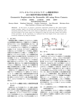
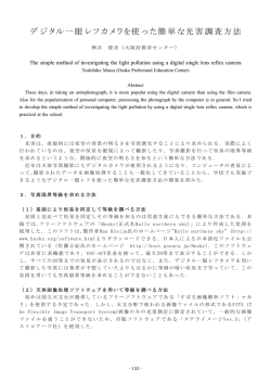
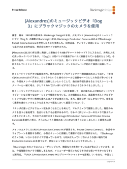
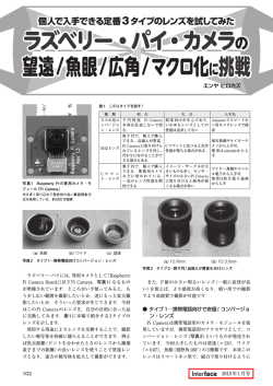
HD ELECTRONIC VIEWFINDER HDVF-20A 電気製品は、安全のための注意事項を守らないと、火災 や人身事故になることがあり、危険です。 このオペレーションマニュアルには、 事故を防ぐための重要な注意事項と製 品の取り扱いかたを示してあります。 このオペレーションマニュアルをよく お読みのうえ、製品を安全にお使いください。お読みになったあとは、いつ でも見られるところに必ず保管してください。 OPERATION MANUAL 1st Edition [Japanese/English] 安全のために 電気製品はまちがった使い方をすると、 火災や感電などにより死亡や大けが など人身事故につながることがあり、危険です。 事故を防ぐために次のことを必ずお守りください。 安全のための注意事項を守る 2(J)ページの注意事項をよくお読みください。 警告表示の意味 このオペレーションマニュアル および製品では、次のような表 示をしています。表示の内容を よく理解してから本文をお読み ください。 定期点検を実施する 長期間安全に使用していただくために、 定期点検を実施することをおすすめ します。点検の内容や費用については、ソニーのサービス担当者または営業 担当者にご相談ください。 故障したら使用を中止する この表示の注意事項を守らない と、火災や感電などにより死亡 や大けがなど人身事故につなが ることがあります。 注意を促す記号 ソニーのサービス担当者または営業担当者にご連絡ください。 万一、異常が起きたら • 異常な音、 , におい、煙 が出たら • 落下させた ら 炎が出たら , 1 カメラの電源を切る。 2 接続コードを抜く。 3 ソニーのサービス担当者または営業担当者に修 理を依頼する。 すぐにカメラの電源を切り、消火する。 行為を禁止する記号 目次 警告 ................................................................................................................ 2(J) 概要 ..................................................................................................................... 3(J) 各部の名称と働き ............................................................................................... 4(J) カメラに取り付ける ............................................................................................ 6(J) 視度と画面を調整する ........................................................................................ 7(J) アイピース部を取り外す ..................................................................................... 8(J) マイクを取り付ける ............................................................................................ 9(J) 表示ランプの名称と働き .................................................................................. 11(J) 交換推奨部品 .................................................................................................... 12(J) 画面や内部をクリーニングする ....................................................................... 13(J) 仕様 .................................................................................................................. 14(J) 1 (J) 日 本 語 警告 下記の注意を守らないと、 火災 感電 火災や感電により死亡や大けがにつながることがあります。 分解しない、改造しない 分解したり、改造したりすると、感電の原因となります。 ビューファインダー内部の調整や点検を行う必要がある場合は、 必ずソニー のサービス担当者にご依頼ください。 内部に水や異物を入れない 水や異物が入ると火災の原因となります。 万一、水や異物が入ったときは、すぐにカメラの電源を切り、接続コードを 抜いて、ソニーのサービス担当者または営業担当者にご相談ください。 油煙、湯気、湿気、ほこりの多い場所では設置• 使用しない 上記のような場所で設置・使用すると、火災や感電の原因となります。 ビューファインダーの接眼レンズを太陽に向けて放置しない 太陽光が接眼レンズを通してビューファインダー内部に焦点を結び、 火災の 原因となることがあります。 2 (J) 概要 HDエレクトロニックビューファインダーHDVF-20Aは、ハイビジョン 着脱可能なアイピース部 カラーカメラ用の 2 型ビューファインダーです。 HDVF-20Aには以下のような特長があります。 アイピース部を取り外して使うと、目を離しても画面の中央がぼや けません。また、画面やミラーにほこりが付着したときは、アイピー ス部を取り外してクリーニングすることができます。 マルチスキャン カメラからの制御信号により、これまでの 60iに加えて、24PsF や その他 50iなどの各種フォーマットに対応します。 別売りの防曇フィルター(サービスパーツ番号:1-547-341-12)を取り 付けると、呼気や水蒸気によるくもりを防ぐことができます。 高性能ブラウン管 • クイックスタートタイプ(電源を入れるのとほとんど同時に画像が現 れます。) • 高解像度 • 低フレア マーカー表示 カメラ側で、センターマーカーやセーフティーゾーンマーカーなどの マーカー表示が ONに設定されている場合、本機のスイッチで、 マーカー表示をON/OFF できます。 3 (J) 各部の名称と働き 1 コネクター ビューファインダーケーブル 2 スライドストッパー 3 タリーランプ(後面) マイクホルダー アイカップ 4 視度調整リング 5 タリーランプ(前面) 6 PEAKINGつまみ 7 CONTRASTつまみ PEAKING CONTRAST BRIGHT 8 BRIGHTつまみ DISPLAY ASPECT ZEBRA ON OFF MOMENT TALLY HIGH OFF LOW 9 TALLYスイッチ 0 ZEBRAスイッチ qa DISPLAY/ASPECTスイッチ 4 (J) 1 コネクター 7 CONTRAST (コントラスト調整)つまみ カメラのVF 端子に接続します。 画面のコントラストを調整します。 カメラの出力信号には影響しませ ん。 2 スライドストッパー 本機をカメラに取り付けて左右にスライドさせるとき、本機がカメラ 8 BRIGHT (明るさ調整)つまみ から外れるのを防ぎます。 画面の明るさを調整します。カメラの出力信号には影響しません。 3 タリーランプ(後面) 9 TALLY (タリー)スイッチ カメラにタリー信号が入力されると点灯します。使わないときは、ふ 本機前面のタリーランプ 5をコントロールします。 たを閉めて隠すことができます。 4 視度調整リング HIGH:タリーランプが明るくなる。 OFF:タリーランプが機能しなくなる。 LOW:タリーランプが暗くなる。 画面の映像が最もはっきり見えるように、 このリングを回して視度を 調整します。 0 ZEBRA (ゼブラパターン)スイッチ ゼブラパターンの表示をコントロールします。 5 タリーランプ(前面) カメラにタリー信号が入力されると点灯します。使わないときは、 TALLYスイッチ9をOFFにします。また、TALLYスイッチ9 で明 ON: ゼブラパターンが表示される。 OFF: ゼブラパターンが消える。 MOMENT: ゼブラパターンが約 5 秒間表示されて消える。 るさを調整できます。 qa DISPLAY/ASPECT(ディスプレイ/アスペクトコント 6 PEAKING (ピーキング調整)つまみ ロール)スイッチ 時計方向に回すと、画面の映像の輪郭が強調され、レンズの マーカー表示のON/OFFおよび画面の表示比率を切り換えます。 フォーカス合わせが容易になります。 カメラの出力信号には影響し DISPLAY: カメラ側でマーカー表示の設定がONになっている ません。 ときは、スイッチをこの位置に押し上げるたびにマーカー表示 の ON/OFFが切り換わります。 ASPECT: スイッチをこの位置に押し下げるたびに、マスク表示 の ON/OFFが切り換わります。 5 (J) カメラに取り付ける 溝 2 スライドガイド 左右位置固定リング スライドストッパー 4 1 3 5 コネクター VF端子 1 カメラの左右位置固定リングをゆるめる。 4 本機を左右にスライドして取り付け位置を決め、カメラの左右 位置固定リングを締める。 2 3 本機裏側の溝をカメラ前面のスライドガイドにはめる。 本機を矢印の方向にスライドさせる。 取り外すときは 取り付け操作の手順を逆に実行します。本機をカメラから抜き取る ときは、スライドストッパーを引き上げてください。 6 (J) 5 コネクターをカメラの VF 端子に差し込む。 視度と画面を調整する 視度を調整するには 視度調整リングを回して、映像が最もはっきり見えるように調整しま す。 視度調整リング 画面を調整するには 下図のつまみを使って、映像の輪郭を強調したり、画面の明るさや コントラストを調整します。 PEAKINGつまみ CONTRASTつまみ PEAKING CONTRAST BRIGHT BRIGHTつまみ ZEBRA DISPLAY ASPECT ON OFF MOMENT TALLY HIGH OFF LOW 7 (J) アイピース部を取り外す ビューファインダーから目を離して撮影するような場合は、 アイピー ス部を外すと、画面全体が見やすくなります。画面やミラーをクリー ◆ クリーニングおよび防曇フィルターの取り付けについて詳しくは、 「画面 や内部をクリーニングする」(13(J)ページ)をご覧ください。 ニングするときや、別売りの防曇フィルターを取り付けるときも、ア イピース部を取り外します。 1 ロックリング ロックリングを反時計方向いっぱいに 回して、 ロックリングの合いマークと本 機筒部の合いマーク(いずれも赤い 線)を合わせる。 ロックリングの合いマーク 筒部の合いマーク 2 アイピース部を抜き取る。 アイピース部先端の合いマーク 再び取り付けるには 1 ロックリングの合いマークと、本機筒部の合いマークを合わせ る。 2 3 ロックリングを時計方向いっぱいに回し、ロックリングの 「LOCK」表示の上の矢印を、本機筒部の合いマークに合わ せる。 アイピース部先端の合いマーク(上記手順2を参照)をロックリ ングの合いマークに合わせて、アイピース部を本機筒部に差 し込む。 8 (J) マイクを取り付ける 以下の手順でマイクを取り付けます。 1 本機のマイクホルダーのネジをゆるめ て開く。 2 マイクホルダーにマイクを取り付け、マ イクホルダーを閉じてネジを締める。 細身のマイクを使うときは、マイクにマ イクロホンスペーサーを取り付ける。 3 マイクの接続コネクターを、カメラの MIC端子か、カメラアダプターのMIC IN 端子に差し込む。 ◆ マイクをカメラアダプターに接続する場合は、マイク切り換えスイッチを 設定する必要があります。詳しくは、使用しているカメラアダプターのマ ニュアルを参照してください。 9 (J) マイクを取り付ける クレードルサスペンションにマイクを取り付けるには クレードルサスペンションCRS-3Pとマイクホルダー(A) (いずれも別 売り)を使ってマイクを取り付けると、振動によるノイズを受けずに録 音することができます。 1 別売りのクレードルサスペンション クレードルサスペンションCRS-3P (別売り) CRS-3Pとマイクホルダー(A) (サービ スパーツ番号:3-680-581-01)を組み 立てる。 2 マイクホルダー (A) (サービスパーツ番号:3-680-581-01) 本機のマイクホルダーのネジをゆるめ て開く。 3 手順1 で、クレードルサスペンションと 組み合わせたマイクホルダー(A)を、 本機のマイクホルダーに取り付け、マ イクホルダーを閉じてネジを締める。 4 クレードルサスペンションにマイクを取 り付ける。マイクの接続コネクターを、 カメラの MIC 端子か、カメラアダプ ターのMIC IN 端子に差し込む。 10 (J) ◆ マイクをクレードルサスペンションに取り付ける方法については、CRS-3Pの取 扱説明書を参照してください。 ◆ マイクをカメラアダプターに接続する場合は、マイク切り換えスイッチを設定す る必要があります。詳しくは、使用しているカメラアダプターのマニュアルを参 照してください。 表示ランプの名称と働き 本機の画面の上下には、カメラの状態や調整の結果を知らせるラ ンプが配置されています。 1 TALLYランプ TALLY/REC BATT 2 BATTランプ 3 TALLY/RECランプ ビューファインダー画面 4 VTR SAVEランプ VTR SAVE 1 TALLY (グリーンタリー)ランプ 5 ランプ 点滅: カメラに取り付けたVTRがサーボロックしていないとき カメラコントロールユニットから、グリーンタリー信号が送られてきた とき点灯(緑)します。 ◆ TALLY/RECランプが点灯/点滅する状況について詳しくは、使用して いるカメラのマニュアルをご覧ください。 2 BATT (バッテリー)ランプ カメラに接続したバッテリーの電圧が下がると点滅します。バッテ リーが使用できなくなると点灯します。 動作中断を防ぐため、バッテリーが点滅を開始した時点で、すば 4 VTR SAVE (VTRセーブ)ランプ カメラに取り付けた VTRが、節電状態になっているとき点灯しま す。 やくバッテリーを交換してください。 5 (注意)ランプ カメラがある特定の状態になったとき点灯します。 どの状態で点灯 ◆ 点滅を開始する電圧を、カメラ側で設定することができます。詳しくは、 使用しているカメラのマニュアルをご覧ください。 させるかは、カメラで設定できます。 3 TALLY/REC (レッドタリー/記録)ランプ ◆ 状況によって赤に点灯または点滅します。 ランプが点灯する条件を設定/確認する方法については、使用して いるカメラのマニュアルをご覧ください。 点灯: • 記録中 • カメラコントロールユニットから、レッドタリー信号が送られて きたとき ご注意 点灯開始時に一瞬明るく点灯しますが、これは注意を促すためで 故障ではありません。 11 (J) 交換推奨部品 本機の以下の部品は経時変化によりひびや割れを生ずることがありますので、ときどき確 認し、必要に応じて交換することを推奨します。 部品名称 ソニー部品番号 備考 マイクスペーサー(φ 21) 3-179-882-0X 付属梱包部品 マイクホルダー(φ 19) 3-680-582-0X マイクラバークッション 3-692-138-0X アイカップ 3-723-079-0X 付属梱包部品 1) 1) 交換時には、上記部品を2 個注文し、上下ペアで交換することを推奨します。 マイクラバークッション アイカップ 12 (J) 画面や内部をクリーニングする 本機の画面や内部をクリーニングするときは、本機をカメラから取 防曇フィルターについて り外し、内部の部品を傷つけないように十分注意して行ってくださ 撮影場所の温度条件によっては、呼気や水蒸気によってプロテク い。 トフィルターがくもり、画面が見にくくなることがあります。プロテクト ◆ 本機をカメラから取り外す方法については、 「カメラに取り付ける」 (6(J) ページ)の手順を参考にしてください。 フィルターの代わりに、別売りの防曇フィルター(サービスパーツ番 号:1-547-341-12)を使用すると、くもりの発生を防ぐことができま す。 画面やミラーの表面からほこりを取り除くときは ブロアーをお使いください。 防曇フィルターを取り付けるには プロテクトフィルターをパッキングごと外し、代わりに防曇フィルター レンズやプロテクトフィルターをクリーニングするときは をはめ込みます。 市販のレンズクリーナーをお使いください。 ご注意 ご注意 防曇フィルターをクリーニングする際は、防曇効果を損なわないよ • シンナーなどの溶剤は、いっさい使わないでください。 うに、柔らかい布でからぶきしてください。 • 防滴とプロテクトフィルターの落下防止のため、 アイカップは必ず 取り付けてください。 • パッキングへのプロテクトフィルターのはめ込み、およびアイカッ 特殊環境使用後のアフターケア プの取り付けは防滴性を損なわないように確実に行ってください。 海辺やほこりの多い地域、温泉地などの取材から帰ってきたときに は、次に示す項目をチェックすることを推奨します。 アイピース部を分解するには 1 1 4 セットの中に入っている砂やほこりをエアーブラシ等で慎重に 取り除く。 2 2 海水中の塩分や温泉中の硫黄分が外装の非塗装面に付着す ると、白く腐食することがある。付着した場合はアルコール等 で速やかにクリーニングする。 筒部 アイカップ ホルダー プロテクト パッキング フィルター アイカップ 3 コネクターの接続面をクリーニングする。 4 一般動作チェックを行い、正常に動作することを確認する。 3 1 本機の筒部から、アイピース部を取り外す。 ◆ 取り外しかたについては、 「アイピース部を取り外す」 (8(J)ページ) をご覧ください。 2 アイカップホルダーからアイカップを外す。 3 アイカップホルダー内から、プロテクトフィルターをパッキングご と外す。 4 パッキングからプロテクトフィルターを外す。 13 (J) 仕様 一般 別売り品 電源 DC 10.5∼ 17V ビューファインダー回転収納機構 BKW-401 消費電力 4W 防曇フィルター(サービスパーツ番号:1-547-341-12) 動作温度 −20 ∼+ 45℃ 老視用接眼レンズ(サービスパーツ番号:A-8262-537-A) 保存温度 −20 ∼+ 50℃ 低倍率レンズ(サービスパーツ番号:A-8262-538-A) 最大外形寸法 239×76×210mm (幅 / 高さ/ 奥行き) 色収差改善ルーペ(サービスパーツ番号:A-8267-737-A) 質量 600g 関連製品 性能 HDカラーカメラHDC-950 ブラウン管 白黒、2 型 水平解像度 500TV 本(画面中心部) 信号方式 BTA-S001および SMPTE274M 規格準拠 HDカムコーダーHDW-F900 仕様および外観は、改良のため予告なく変更することがあります 対応フォーマット が、ご了承ください。 有効走査線数 /フォーマット/ 水平走査線周波数 / 垂直走査線周波数 1080/ 23.98PsF/ 26.97kHz/ 47.95Hz 1080/ 24PsF/ 27kHz/ 48Hz 1080/ 25PsF/ 28.13kHz/ 50Hz 1080/ 29.97PsF/ 33.72kHz/ 59.94Hz 1080/ 30PsF/ 33.75kHz/ 60Hz 1080/ 50i/ 28.13kHz/ 50Hz 1080/ 59.94i/ 33.72kHz/ 59.94Hz 1080/ 60i/ 33.75kHz/ 60Hz 1035/ 59.94i/ 33.72kHz/ 59.94Hz 1035/ 60i/ 33.75kHz/ 60Hz ビデオ入力 1.0 Vp-p± 6 dB、75 Ω終端 表示ランプ REC/TALLY、BATT、VTR SAVE、 付属品 マイクスペーサー(ゼンハイザー用、φ 19)(1) マイクスペーサー(オーディオテクニカ用、φ 21)(1) オペレーションマニュアル(1) 14 (J) WARNING To prevent fire or shock hazard, do not expose the unit to rain or moisture. Dangerously high voltages are present inside the set. Do not open the cabinet. Refer servicing to qualified personnel only. For the customers in the USA This equipment has been tested and found to comply with the limits for a Class A digital device, pursuant to Part 15 of the FCC Rules. These limits are designed to provide reasonable protection against harmful interference when the equipment is operated in a commercial environment. This equipment generates, uses, and can radiate radio frequency energy and, if not installed and used in accordance with the instruction manual, may cause harmful interference to radio communications. Operation of this equipment in a residential area is likely to cause harmful interference in which case the user will be required to correct the interference at his own expense. You are cautioned that any changes or modifications not expressly approved in this manual could void your authority to operate this equipment. The shielded interface cable recommended in this manual must be used with this equipment in order to comply with the limits for a digital device pursuant to Subpart B of Part 15 of FCC Rules. For the customers in Europe This product with the CE marking complies with the EMC Directive (89/336/EEC) issued by the Commission of the European Community. Compliance with this directive implies conformity to the following European standards: • EN55103-1: Electromagnetic Interference (Emission) • EN55103-2: Electromagnetic Susceptibility (Immunity) This product is intended for use in the following Electromagnetic Environment(s): E1 (residential), E2 (commercial and light industrial), E3 (urban outdoors) and E4 (controlled EMC environment, ex. TV studio). Pour les clients européens Ce produit portant la marque CE est conforme à la Directive sur la compatibilité électromagnétique (EMC) (89/336/CEE) émise par la Commission de la Communauté européenne. La conformité à cette directive implique la conformité aux normes européennes suivantes: • EN55103-1: Interférences électromagnétiques (émission) • EN55103-2: Sensibilité électromagnétique (immunité) Ce produit est prévu pour être utilisé dans les environnements électromagnétiques suivants: E1 (résidentiel), E2 (commercial et industrie légère), E3 (urbain extérieur) et E4 (environnement EMC contrôlé ex. studio de télévision). Für Kunden in Europa Dieses Produkt besitzt die CE-Kennzeichnung und erfüllt die EMV-Direktive (89/336/EEC) der EG-Kommission. Die Erfüllung dieser Direktive bedeutet Konformität für die folgenden Europäischen Normen: • EN55103-1: Elektromagnetische Interferenz (Emission) • EN55103-2: Elektromagnetische Empfindlichkeit (Immunität) Dieses Produkt ist für den Einsatz unter folgenden elektromagnetischen Bedingungen ausgelegt: E1 (Wohnbereich), E2 (kommerzieller und in beschränktem Maße industrieller Bereich), E3 (Stadtbereich im Freien) und E4 (kontrollierter EMV-Bereich, z.B. Fernsehstudio). Table of Contents 1(E) English Outline.................................................................................................. 2(E) Location and Function of Parts .......................................................... 3(E) Attaching the Viewfinder to a Camera .............................................. 5(E) Adjusting the Focus and Screen ......................................................... 6(E) Detaching the Eyepiece....................................................................... 7(E) Attaching a Microphone..................................................................... 8(E) Name and Function of the Indicators .............................................. 10(E) Recommended consumable parts ..................................................... 11(E) Cleaning the Screen or Interior ........................................................ 12(E) Specifications...................................................................................... 13(E) Outline The HDVF-20A HD Electronic Viewfinder is a 2-type screen viewfinder designed for use with highdefinition color video cameras. It has the following features. Multiscan In addition to the 60i format, formats such as 24PsF and 50i are supported for control signals from the camera. High-performance CRT • Quick-start type (The image appears as soon as the camera is turned on.) • Enhanced resolution • Reduced flare Marker indication When the camera setting allows the center marker or safety zone marker indication, the viewfinder can set the marker indication on or off. 2(E) Removable eyepiece Detaching the eyepiece gives you a clear view of the center of the screen even with your eye away from the viewfinder. You can clean dust from the screen or the mirror by detaching the eyepiece. Other features Fitting a fog-proof filter (Part No. 1-547-341-12, not supplied) over the viewfinder lens prevents breath or vapor condensation on the lens. Location and Function of Parts 1 Plug Viewfinder cable 2 Stopper 3 Tally indicator (rear) Microphone holder Eyecup 4 Diopter adjustment ring 5 Tally indicator (front) 6 PEAKING control 7 CONTRAST control PEAKING CONTRAST BRIGHT 8 BRIGHT control DISPLAY ASPECT ZEBRA ON OFF MOMENT TALLY HIGH OFF LOW 9 TALLY switch 0 ZEBRA switch qa DISPLAY/ASPECT switch 3(E) Location and Function of Parts 1 Plug Connect to the VF connector on the camera. 2 Stopper Prevents the viewfinder from coming off the camera when it is slid from side to side. 3 Tally indicator (rear) Lights up when the camera receives a tally control signal. This indicator can be covered when not in use. 4 Diopter adjustment ring Allows for optimal foucus adjustment. 5 Tally indicator (front) Lights up when the camera receives a tally control signal. Set the TALLY switch 9 to OFF when not in use. The brightness can also be adjusted with the TALLY switch 9. 6 PEAKING control Turning this control clockwise adjusts the picture sharpness, and makes focusing easier. This control has no effect on the output signals of the camera. 7 CONTRAST control Adjusts the contrast of the screen. This control has no effect on the output signals of the camera. 8 BRIGHT control Adjusts the brightness of the screen. This control has no effect on the output signals of the camera. 9 TALLY switch Controls the tally indicator 5 located on the front of the viewfinder. HIGH: The tally indicator brightness is set to high. OFF: The tally indicator is disabled. LOW: The tally indicator brightness is set to low. 4(E) 0 ZEBRA (zebra pattern) switch Controls the zebra pattern display on the viewfinder screen as follows: ON: A zebra pattern appears and stays. OFF: The zebra pattern disappears. MOMENT: A zebra pattern appears and stays for about 5 seconds. qa DISPLAY/ASPECT switch Turns the marker indication on and off, and switches between 4:3 and 16:9 aspect ratios for viewfinder screen display. DISPLAY: When the marker indication is enabled with the camera, the marker indication on the viewfinder screen turns on and off every time you push the switch up to this position. ASPECT: Each push of the switch down to this position toggles the mask display on and off. Attaching the Viewfinder to a Camera Slide rail 2 Slide guide Left-right positioning ring Stopper 4 1 3 5 Plug VF connector 1 Loosen the left-right positioning ring on the camera. 2 Insert the slide guide which is located on the front of the camera into the slide rail which is located on the back of the viewfinder. 3 4 Position the viewfinder by sliding it from side to side, and tighten the left-right positioning ring on the camera. 5 Connect the plug to the VF connector on the camera. Slide the viewfinder in the direction of the arrow. Detaching the viewfinder To detach the viewfinder from the camera, conduct the attachment procedure in reverse. When removing the viewfinder from the camera, pull up the stopper. 5(E) Adjusting the Focus and Screen Adjusting the focus Turn the diopter adjustment ring until the image is sharpest for your eyesight. Diopter adjustment ring Adjusting the screen To adjust the peaking, brightness and contrast of the viewfinder screen rotate the controls which are illustrated below. PEAKING control CONTRAST control PEAKING CONTRAST BRIGHT BRIGHT control ZEBRA DISPLAY ASPECT 6(E) ON OFF MOMENT TALLY HIGH OFF LOW Detaching the Eyepiece Detaching the eyepiece gives you a clear view of the screen even with your eye away from the viewfinder. Detach the eyepiece to clean the screen and mirror, and to attach the optional fog-proof filter. 1 For details on cleaning the viewfinder or attaching the fogproof filter, see “Cleaning the Screen or Interior” on page 12(E). Locking ring Turn the eyepiece locking ring fully counterclockwise to line up the red match mark on the locking ring with the red match mark on the viewfinder barrel. Locking ring match mark Match mark on the viewfinder barrel 2 Detach the eyepiece. Match mark on end of eyepiece Refitting the eyepiece 1 Align the match mark on the eyepiece locking ring with that on the viewfinder barrel. 2 Align the match mark on the end of the eyepiece (see step 2 above) with that of the eyepiece locking ring, then insert the eyepiece into the viewfinder barrel. 3 Turn the eyepiece locking ring clockwise until its “LOCK” indication arrow points to the match mark on the viewfinder barrel. 7(E) Attaching a Microphone Proceed as follows to attach a microphone. 1 Loosen the screw of the microphone holder and open the holder. 2 Attach the microphone to the microphone holder, then close the holder and tighten the screw. When necessary to use a slender microphone, attach a microphone spacer to the microphone beforehand. 3 Insert the microphone plug into the MIC connector on the camera, or the MIC IN connector on the camera adaptor. 8(E) When connecting the microphone to the camera adaptor, you will need to set the microphone selector. For details, see the manual supplied with your camera adaptor. Attaching the microphone to the cradle suspension Using the optional CRS-3P Cradle Suspension and microphone holder (A) will reduce noise caused by vibration. 1 Combine together the CRS-3P Cradle Suspension and the microphone holder (A) (Part No. 3-680-581-01). CRS-3P Cradle Suspension (not supplied) Microphone holder (A) (Part No. 3-680-581-01) 2 Loosen the screw on the microphone holder on the viewfinder, and open the holder. 3 Attach the microphone holder (A) and cradle suspension combined in Step 1 to the microphone holder on the viewfinder, then close the holder and tighten the screw. 4 Attach the microphone to the cradle suspension. Insert the microphone plug into the MIC connector on the camera, or the MIC IN connector on the camera adaptor. See the manual supplied with the CRS-3P for instructions on how to attach the microphone to the cradle suspension. When connecting the microphone to the camera adaptor, you will need to set the microphone selector. For details, see the manual supplied with your camera adaptor. 9(E) Name and Function of the Indicators The following indicators are arranged above and below the viewfinder screen to show the status or settings of the camera. 1 TALLY indicator TALLY/REC BATT 2 BATT indicator 3 TALLY/REC indicator Viewfinder screen 4 VTR SAVE indicator VTR SAVE 1 TALLY indicator (green) Lights up when the camera receives a green tally control signal from the camera control unit. 2 BATT indicator Starts flashing when the battery voltage supplied to the camera drops below the minimum level, and stays lit when the battery is exhausted. To prevent interruption during operation, replace the battery as soon as this indicator starts flashing. The level at which the indicator starts flashing can be set on the camera. For more details, see the manual supplied with your camera. 3 TALLY/REC indicator (red) Depending on the status, this indicator will light up or flash. When lit: • The image shot by the camera is being recorded. • A red tally control signal has been received from the camera control unit. Note This indicator will be brighter than usual for a moment after it is first lit. This is only a warning, and not a malfunction. 10(E) 5 indicator When flashing: The servo system of the VTR attached to the camera is unlocked. For more details on the status by which the TALLY/REC indicator will light or flash, see the manual supplied with your camera. 4 VTR SAVE indicator Lights up when the VTR attached to the camera is set to power save mode. 5 (warning) indicator Lights up when the camera is used under certain conditions. These conditions can be specified on the camera. See the manual supplied with your camera for more details on specifying or checking the conditions by which the indicator will light up. Recommended consumable parts The following parts may crack with the passage of time. Check them occasionally and replace as required. Item Part No. Remarks Microphone spacer (diameter 21 mm) 3-179-882-0X Supplied packing accessory Microphone holder (diameter 19 mm) 3-680-582-0X Supplied packing accessory Microphone rubber cushion 3-692-138-0X1) Eyecup 3-723-079-0X 1) Order two items and replace them in pairs. Microphone rubber cushions Eyecup 11(E) Cleaning the Screen or Interior When cleaning the screen or the interior of the viewfinder, detach the viewfinder from the camera, then clean it taking care not to damage the components. For information about detaching the viewfinder from the camera, see the procedure explained in “Attaching the Viewfinder to a Camera” on page 5(E). To remove dust from the screen or the mirror Use a dust blower. To clean the lens or the protecting filter Use a commercially available lens cleaner. Notes • Do not use organic solvents such as thinners. • To protect the eyepiece from moisture and prevent the protective filter from coming off, be sure to always attach the eyecup. • To assure protection from moisture, attach firmly when attaching the protective filter to the packing ring and the eyecup to the eyecup holder. Disassembling the eyepiece for cleaning Viewfinder barrel Eyecup holder 2 Protecting Packing filter ring Remove the protecting filter, together with the packing ring, from inside the eyecup holder. 4 Detach the protecting filter from the packing ring. Fog-proof filter Depending on the temperature and humidity, the protecting filter may mist, especially if you breathe near it. You can replace the protecting filter with an optional fog-proof filter (Part No. 1-547-341-12) to prevent the fogging. Attaching the fog-proof filter Remove the protecting filter together with the packing ring, and in their place attach the fog-proof filter. Note When cleaning the fog-proof filter, wipe the filter very gently with a soft cloth to avoid impairing the antifogging effect. Check the viewfinder after using it in harsh environments Check the following points after using the viewfinder in a harsh environment such as a beach, a dusty area, or a hot spring resort. 1 4 3 1 Use an airbrush to carefully remove any dust or sand from inside the viewfinder. 2 Salt from seawater or sulfur from hot springs can result in whitish corrosion on the non-painted surfaces of the viewfinder. Use a cleaning solution such as ethanol to remove any adhering salt or sulfur from the non-painted surfaces as soon as possible. 3 4 Clean the contacts of the connector. Eyecup 3 1 Detach the eyepiece from the viewfinder barrel. For the detaching procedure, see “Detaching the Eyepiece” on page 7(E). 2 Remove the eyecup from the eyecup holder. 12(E) Check that the viewfinder is working correctly. Specifications General Accessories Power requirements 10.5 to 17 V DC Power consumption 4W Operating temperature –20˚C to +45˚ C (–4˚F to +113˚F) Storage temperature –20˚C to +50˚C (–4˚F to 122˚F) External dimensions 239 × 76 × 210 mm (9 1/2 × 3 × 8 3/8 inches) (w/h/d) Mass 600 g (1 lb 5 oz) Microphone spacer (diameter 19 mm) (1) Microphone spacer (diameter 21 mm) (1) Operation manual (1) Accessories not supplied BKW-401 Viewfinder Rotation Bracket Fog-proof filter (Part No. 1-547-341-12) Lens assembly (farsighted) (Part No. A-8262-537-A) Lens assembly (low magnification) (Part No. A-8262538-A) Lens assembly (standard magnification with special compensation for aberrations) (Part No. A-8267737-A) Performance CRT 2-type monochrome Horizontal resolution 500 TV lines (at center) Signal system Conforming to BTA-S001 and SMPTE274M standards Supported formats Effective scanning lines / Format / Horizontal scanning frequency / Vertical scanning frequency 1080/ 23.98PsF/ 26.97kHz/ 47.95Hz 1080/ 24PsF/ 27kHz/ 48Hz 1080/ 25PsF/ 28.13kHz/ 50Hz 1080/ 29.97PsF/ 33.72kHz/ 59.94Hz 1080/ 30PsF/ 33.75kHz/ 60Hz 1080/ 50i/ 28.13kHz/ 50Hz 1080/ 59.94i/ 33.72kHz/ 59.94Hz 1080/ 60i/ 33.75kHz/ 60Hz 1035/ 59.94i/ 33.72kHz/ 59.94Hz 1035/ 60i/ 33.75kHz/ 60Hz Video input 1.0 Vp-p±6 dB, 75-Ω terminated Indicators REC/TALLY, BATT, VTR SAVE, Related equipment HDC-950 HD Color Video Camera HDW-F900 HD Camcorder Design and specifications are subject to change without notice. 13(E) The material contained in this manual consists of information that is the property of Sony Corporation and is intended solely for use by the purchasers of the equipment described in this manual. Sony Corporation expressly prohibits the duplication of any portion of this manual or the use thereof for any purpose other than the operation or maintenance of the equipment described in this manual without the express written permission of Sony Corporation. Le matériel contenu dans ce manuel consiste en informations qui sont la propriété de Sony Corporation et sont destinées exclusivement à l’usage des acquéreurs de l’équipement décrit dans ce manuel. Sony Corporation interdit formellement la copie de quelque partie que ce soit de ce manuel ou son emploi pour tout autre but que des opérations ou entretiens de l’équipement à moins d’une permission écrite de Sony Corporation. Das in dieser Anleitung enthaltene Material besteht aus Informationen, die Eigentum der Sony Corporation sind, und ausschließlich zum Gebrauch durch den Käufer der in dieser Anleitung beschriebenen Ausrüstung bestimmt sind. Die Sony Corporation untersagt ausdrücklich die Vervielfältigung jeglicher Teile dieser Anleitung oder den Gebrauch derselben für irgendeinen anderen Zweck als die Bedienung oder Wartung der in dieser Anleitung beschriebenen Ausrüstung ohne ausdrückliche schriftliche Erlaubnis der Sony Corporation. HDVF-20A (SY, 和、英) 3-203-934-01(1) Sony Corporation Communication System Solutions Network Company Printed in Japan 2000.02.13 2000
© Copyright 2026 Paperzz