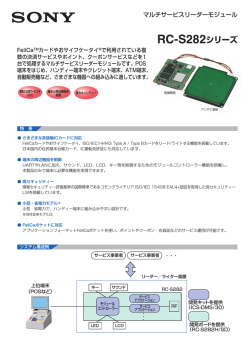
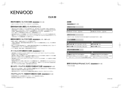
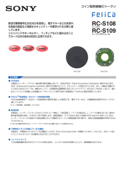
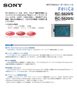
3-869-380-12 (1)
PCS-G70/G70P
Supplement for Video
Communication System
操作ガイド
JP
最初にお読みください!
Operation Guide
GB
Please read this before proceeding!
Guide d’utilisation
FR
Lisez-le avant de continuer!
Bedienanleitung
DE
Lesen Sie sie bitte, bevor Sie fortfahren!
Guía de functionamiento
ES
Léalo antes de continuar!
Guida per l’uso
IT
Leggere attentamente prima di procedere!
CS
Guia de Operação
Leia antes de continuar!
PCS-G70/G70P
© 2005 Sony Corporation
PT
警告表示の意味
安全のために
ソニー製品は安全に充分配慮して設計されていま
す。し か し、電 気 製 品 は、ま ち が っ た 使 い か た を す
ると、火災や感電などにより死亡や大けがなど人身
事故につながることがあり、
危険です。
事故を防ぐために次のことを必ずお守りください。
安全のための注意事項を守る
6 ~ 9 ページの注意事項をよくお読みください。
定期点検をする
長 期 間、安 全 に お 使 い い た だ く た め に、
定期点検を
することをおすすめします。
点検の内容や費用については、お買い上げ店または
ソニーのサービス窓口にご相談ください。
故障したら使わない
すぐに、お買い上げ店またはソニーのサービス窓口
にご連絡ください。
万一、異常が起きたら
・
・
・
・
煙が出たら
異常な音、
においがしたら
内部に水、
異物が入ったら
製品を落としたりキャビネットを破損したときは
m
1 電源を切る。
2 電源コードや接続コードを抜く。
3 お買い上げ店またはソニーのサービス窓口に連絡
する。
JP
2
取扱説明書および製品
で は、次 の よ う な 表 示
を し て い ま す。
表示の
内容をよく理解してか
ら本文をお読みくださ
い。
この表示の注意事項を
守 ら な い と、
火災や感
電などにより死亡や大
けがなど人身事故につ
ながることがありま
す。
この表示の注意事項を
守 ら な い と、
感電やそ
の他の事故によりけが
をしたり周辺の物品に
損害を与えたりするこ
とがあります。
注意を促す記号
行為を禁止する記号
行為を指示する記号
CD-ROM 内の説明書を読むには
付属の説明書につい
て
付属の CD-ROM には、本機の説明書
本機には、この操作ガイドをはじめと
ROM 内の説明書をお読みになるに
は、Adobe® Acrobat®* Reader 5.0J
して、次の説明書が付属しています。
が PDF 形式で入っています。CD-
目的に応じてお読みください。
または Acrobat Reader 6.0J が必要
操作ガイド(本書)
パソコンに Adobe Reader がインス
2 地点間のビデオ会議で日常の会議を
トールされていない場合は、4 ページ
始めるところから終了するまでの操作
に示したホームページからダウンロー
や、システムの接続方法などを簡単に
ドしてください。
です。
説明しています。
(付属の CD-ROM
にも同じ操作ガイドが収録されていま
す。)
取扱説明書の見かた
1
CD-ROM ドライブに付属の CD-
簡単接続ガイド / リモコン操作ガイド
ROM「Manuals for Video
ワンタッチダイヤルを使って会議を始
Communication System」を
める方法と、通信中に使うリモコンの
挿入する。
機能を簡単に説明しています。
しばらくすると、画面に CD-ROM
の内容が表示されます。
取扱説明書(付属の CD-ROM 内)
本機の詳しい操作方法や会議に必要な
さまざまな設定など、本機の機能をす
べて説明しています。
2
「 Japanese」というファイル名
の PDF をダブルクリックする。
Adobe Reader が起動し、本機の
WEB 機能取扱説明書(付属の CD-
取扱説明書の表紙が画面に表示され
ROM 内)
ます。
Web ブラウザを介して本機をコント
「目次」の各項目をクリックすると、そ
ロールしたり、設定を行う方法を説明
の見出しのページが表示されます。
しています。
接続シート
周辺機器や配線の接続方法を、LAN 接
続、ISDN 接続に分けて説明していま
す。
3 JP
Adobe Reader 6.0J のインストー
ル
Adobe Reader 6.0J をインストール
するために必要なハードウェア、ソフ
トウェアは以下のとおりです。
・ Intel® Pentium® または 100 パーセ
ント互換のプロセッサを搭載したパ
ソコン
・ Microsoft® Windows®** 98 SE、
Windows Millennium、Windows
NT®** 4.0 Service Pack 5 または
Windows 2000 以降
・ 64MB 以上の RAM
・ 70MB 以上のハードディスクの空き
容量
Adobe Reader は下記のホームページ
から最新版が無料で入手できます。
日本向け http://
www.adobe.co.jp/products/
acrobat/readstep.html
北米向け http://
www.adobe.com/products/
acrobat/readstep.html
欧州向け http://
www.adobe.com/products/
acrobat/acrrcenteuro.html
.......................................................................
“IPELA”および は、ソニー株式会社の商標です。
* Adobe、Acrobat は Adobe Systems Incorporated(アドビシステムズ社)の商標
です。
** Windows、Windows NT は、米国 Microsoft Corporation の米国および他の国にお
ける登録商標です。
JP
4
目次
警告...........................................6
注意...........................................7
電池についての安全上のご注意 ..... 9
電源を入れる .............................. 10
相手を呼び出す ........................... 11
映像や音声を調節する ................ 14
カメラアングルとズームを
調節する ........................... 14
音量を調節する ...................... 15
会議を終了する ........................... 16
JP
回線を切る ............................. 16
システムをスタンバイ
状態にする ....................... 16
ヘルプを表示する ....................... 18
システムの構成 ........................... 19
基本システムを
構成する機器 .................... 19
別売り機器の一覧 .................. 20
システムの接続 ........................... 24
接続例(LAN 接続)............... 24
接続例(ISDN 接続) ............. 25
仕様
.......................................... 26
付属の CD-ROM には、
本機のより詳し
い情報を記載した取扱説明書が収録され
ています。操作ガイドと併せてお読みく
ださい。
目次
5 JP
下記の注意を守らないと、 火災や感電により
死亡や大けがにつながることがあります。
AC 電源コードや DC 電源接続コー
ドを傷つけない
AC 電源コードや DC 電源
接続コードを傷つけると、火
災や感電の原因となること
があります。
・ コードを加工したり、傷
つけたりしない。
・ 重いものをのせたり、
引っ張ったりしない。
・ 熱器具に近づけたり、加
熱したりしない。
・ コードを抜くときは、必
ずプラグを持って抜く。
万一、
コードが傷んだら、ソ
ニーのサービス窓口に交換
をご依頼ください。
雨のあたる場所や、油煙、湯気、ほ
こりの多い場所には置かない
火災や感電の原因となるこ
とがあります。
JP
6
警告
下記の注意を守らないと、 けがをしたり周辺の物品に
損害を与えることがあります
不安定な場所に設置しない
ぐらついた台の上や傾いた
ところに設置すると、倒れた
り落ちたりしてけがの原因
となることがあります。
ま
た、
設置・取り付け場所の強
度を充分にお確かめくださ
い。
通気孔をふさがない
通気孔をふさぐと、本機内部
に熱がこもり、発煙、
発火な
どが起こり、やけどの原因に
なることがあります。
接続の際は電源を切る
電源を入れたままで電源
コードや接続ケーブルを接
続すると、
感電や故障の原因
になることがあります。
付属の AC アダプターや、電源コー
ド、接続コードを使う
付属の AC アダプターや電
源コード、
接続コードを使わ
ないと、感電や故障の原因に
なることがあります。
付属の AC アダプターは指定された
製品以外には使用しない
指定された製品以外に使用
すると、故障の原因になるこ
とがあります。
ぬれた手で電源プラグにさわらない
ぬれた手で電源プラグの抜
き差しをすると、感電の原因
となることがあります。
ぬれた手で AC アダプターにさわら
ない
感電の原因となることがあ
ります。
分解や改造をしない
火災や感電、
けがの原因とな
ることがあります。
内部の点
検や修理はお買い上げ店ま
たはソニーのサービス窓口
にご依頼ください。
お手入れの際は、電源を切って電源
プラグを抜く
電源を接続したままお手
入れをすると、
感電の原因
となることがあります。
移動させるときは電源コード、接続
コードを抜く
接続したまま移動させると、
コードが傷つき、火災や感電
の原因となることがありま
す。
注意
7 JP
下記の注意を守らないと、 けがをしたり周辺の物品に
損害を与えることがあります
直射日光に当たる場所、熱器具の近
くには置かない
変形したり、故障したりする
だけでなく、レンズの特性に
より火災の原因となります。
特に窓際に置くときなどは
ご注意ください。
内部に水や異物を入れない
水や異物が入ると火災や感
電の原因となることがあり
ます。
万一、水や異物が入ったとき
は、
すぐに電源を切り、電源
コードや接続コードを抜い
て、
お買い上げ店またはソ
ニーのサービス窓口にご相
談ください
電源コードや接続ケーブルに足を
引っかけない
電源コードや接続ケーブル
は、
足に引っかけると本機の
落下や転倒などによりけが
の原因となることがありま
す。
十分注意して接続・配置して
ください。
JP
8
注意
電池についての安全
上のご注意
漏液、発熱、発火、破裂などを避けるた
め、下記の注意事項を必ずお守りくださ
い。
・ 火 の 中 に 入 れ な い。
シ ョ ート させ た
り、分解、
加熱しない。
・ 充電しない。
・ 指定された種類の電池を使用する。
・ +と-の向きを正しく入れる。
・ 電池を使い切ったとき、
長時間使用し
ないときは、
取り出しておく。
・ 新しい電池と使用した電池、
種類の違
う電池を混ぜて使わない。
もし電池の液が漏れたときは、電池入
れの液をよくふきとってから、新しい
電池を入れてください。万一、液が身
体についたときは、水でよく洗い流し
てください。
本機を廃棄する場合は、内蔵の電池
を小型化学廃棄物として処理する必
要がありますので、ソニーのサービ
ス窓口にご相談ください。
電池についての安全上のご注意
9 JP
電源を入れる
1
モニター用テレビの電源を入れる。
2
会議で使用するその他の機器の電源を入れる。
3
コミュニケーションターミナルの前面パネルを開けて、右側の電
源スイッチをオン(" 側)にする。
カメラ
コミュニケーション
ターミナル
POWER ランプ
(緑に点灯)
電源スイッチ
しばらくすると、コミュニケーションターミナルの電源が入ります。
コミュニケーションターミナル前面の 3 つのランプとカメラの
POWER ランプがいったんすべて点灯し、その後、POWER ランプ
だけが緑色に点灯します。
モニター用テレビにはランチャーメニューが表示され、自分側のカメ
ラが写している映像も表示されます。
JP
10
電源を入れる
相手を呼び出す
ここでは、ランチャーメニューで電話番号や IP アドレスを入力して
相手を呼び出す方法を説明します。
1
ランチャーメニュー下部のドロップダウンリストから回線イン
ターフェースを選ぶ。
リモコンの V/v/B/b ボタンでランチャーメニュー下部の「回線種別」
を選び、決定ボタンを押すとドロップダウンリストが表示されます。V
または v ボタンで使用する回線インターフェースを選び、決定ボタン
を押してください。
回線インターフェースは、
ISDN 回線に接続している場合に選びます。
ISDN 回線に接続していない場合には、
「IP」と表示されます。
回線種別
番号入力欄
ダイヤル
上に移動
左に
移動
右に
移動
下に移動
AUTO: 番号入力欄に入力した内容に応じて本機が自動的に回線種別
を切り替えます。
IP: LAN を使ってビデオ会議システムと接続する場合に選びます。
ISDN: ISDN 回線でビデオ会議システムと接続する場合に選びま
す。
相手を呼び出す
11 JP
TEL: ISDN 回線で音声のみの電話と接続する場合に選びます。
(ボイスミーティング)
2
相手の IP アドレス(IP のとき)または電話番号(ISDN または
TEL のとき)を番号入力欄に入力する。
リモコンの V/v/B/b ボタンで番号入力欄を選び、決定ボタンを押し
ます。その後、リモコンの数字ボタンで数字を入力します。
1 消去ボタン
2 後退ボタン
3
b ボタン
4 数字ボタン
1 消去ボタン:一行すべて消去します。
2 後退ボタン:一文字消去します。
3 b ボタン:IP の場合、「.」(ピリオド)を入力します。
4 数字ボタン:電話番号や IP アドレスを入力します。
ご注意
番号入力欄には 0 発信などの発信番号(プリフィックス)を入力しな
いでください。プリフィックスは、発信設定メニューの 2 ページ目で設
定できます。詳しくは、取扱説明書をご覧ください。
JP
12
相手を呼び出す
3
ダイヤルボタンを押すか、またはリモコンの接続 / 切断(
/
)ボタンを押して相手を呼び出す。
リモコンの V/v/B/b ボタンを押して、
「ダイヤル」を選び、決定ボタン
を押す。
またはリモコンの接続 / 切断(
/
)ボタンを押すとダイヤ
ルが始まり、
「発信中」と表示されます。相手とつながると「ミーティン
グを始めます。」と表示され、以下のような画面になります。
自分側の映像
相手側の映像
手順 3 で下記のダイヤログが表示されたら
TOKYO
192.168.1.57
呼び出しを中止します。
相手を呼び出します。
通信モードに関する詳細な設定ができ
ます。
発信設定メニューの「詳細設定」が「オン」のときは、上記のダイアログ
が表示されます。
相手を呼び出す
13 JP
映像や音声を調節する
カメラアングルとズームを調節する
通信していないとき
リモコンの V/v/B/b ボタンを押してランチャーメニューの映像を選
び、決定ボタンを押します。その後、V/v/B/b ボタンを押してカメ
ラアングルを調節し、ズームボタンを押してズームを調節します。調
節し終ったら決定ボタンを押します。
アングルの調節
上に移動
左に
移動
右に
移動
下に移動
ズームの調整
映像が大きくなる
映像が小さくなる
通信していないときは…
通信中は…
自分側の映像
JP
14
映像や音声を調節する
相手側の映像
通信しているとき
リモコンの V/v/B/b ボタンとズームボタンで、自分側の映像のカメ
ラアングルとズームを調節できます。
相手側の映像のカメラアングルを調整する場合は、取扱説明書をご覧
ください。
音量を調節する
相手から送られてくる音声を調節するには
リモコンの音量+ / -ボタンを押します。
自分側から相手に送られる音声を一時的に消すには
リモコンのマイクオン / オフボタンを押します。
モニター画面に「MIC OFF」と表示されます。もう一度押すと音声
が再び送られます。
押すと音声が切れる
音量が大きくなる
音量が小さくなる
映像や音声を調節する
15 JP
会議を終了する
回線を切る
1
リモコンの接続/切断(
/
)ボタンを押す。
モニター画面に「切断しますか?」と表示されます。
2
リモコンの B または b ボタンを押して「OK」を選び、決定ボタン
を押す。または、リモコンの接続/切断(
/
)ボタンをもう
一度押す。
これで相手との回線が切れ、ランチャーメニューに戻ります。
システムをスタンバイ状態にする
1
リモコンの @/1 ボタンを押す。
モニター画面に「電源を切りますか?」と表示されます。
JP
16
会議を終了する
2
リモコンの B または b ボタンを押して「OK」を選び、決定ボタン
を押す。または、リモコンの @/1 ボタンをもう一度押す。
スタンバイ状態になり、コミュニケーションターミナルの POWER ラ
ンプがオレンジ色に点灯します。
POWER ランプ(消灯)
POWER ランプ
(オレンジに点灯)
`/1 ボタン
B/b ボタンと決定
ボタン
この状態にしておくと、リモコンの @/1 ボタンで電源を入れること
ができます。
相手から呼び出しを受けると、スタンバイモードは解除されて着信し
ます。
電源を切るには
コミュニケーションターミナルの前面パネルを開けて、右側の電源ス
イッチをオフ(○側)にし、会議に使用したその他の機器の電源を切
ります。
会議を終了する
17 JP
ヘルプを表示する
リモコンのヘルプボタンを押すと、操作案内用のバルーンヘルプまた
はヘルプ画面が表示されます。
ヘルプ画面を消すには、もう一度ヘルプボタンを押します。
JP
18
ヘルプを表示する
システムの構成
PCS-G70 は、テレビ会議をするために必要な基本システムと、より
充実した会議を行うための別売り機器で構成されます。
基本システムを構成する機器
ビデオコミュニケーションシステム PCS-G70 は、PCS-G70 テレビ
会議システムの中心をなす基本システムです。ビデオコミュニケー
ションシステム PCS-G70 は以下の機器で構成されています。
機器
説明
コミュニケーションターミ
映像、音声信号を処理して送受信するコー
ナル
デック部、
音声のエコーをカットするエコー
PCS-PG70
キャンセラーおよび通信回線とのインター
フェース部、システム制御部からなります。
カメラユニット
会議を撮影するカメラです。
PCSA-CG70
リモコン
コミュニケーションターミナルとカメラを操
PCS-RG70
作します。
AC アダプター
コミュニケーションターミナルに電源を供給
PCS-AC19V6
します。
システムの構成
19 JP
機器
説明
IR リピーター
モニター用テレビの電源をコミュニケーショ
ンターミナルと連動させます。
別売り機器の一覧
テレビ
会議を行うには、映像モニター用のテレビが必要です。
機器
説明
映像モニター用テレビ、プ
映像モニター、スピーカーとして使用しま
ロジェクターなど
す。
専用別売り機器
会議を充実させるために、以下の別売り機器が用意されています。
機器
説明
スタンド
コミュニケーションターミナルを立てて設置
PCSA-STMG70
できるスタンドです。
カメラスタンド
カメラユニット用のスタンドです。
PCSA-STCG70
JP
20
システムの構成
機器
説明
カメラユニット
会議を撮影するカメラです。出席者の顔や話
PCSA-CTG70
している人の方位を自動的に検出して撮影で
きます。
ISDN ユニット
ISDN 回線に接続します。
最大 3 回線、6B
PCSA-B384S
チャンネルでの接続が可能です。
ISDN ユニット
ISDN 回線に接続します。
最大 6 回線、12B
PCSA-B768S
チャンネルでの接続が可能です。
ISDN ユニット
PRI 回線インターフェースで ISDN 回線に接
PCSA-PRI
続できます。
(現在国内では発売されていません。)
データソリューションボッ
コンピューターやプロジェクターを接続し
クス
て、
データ会議ができます。
PCSA-DSB1S
マイクロホン
どの方向からの音でも拾える無指向性のマイ
PCS-A1
クです。静かな部屋での会議におすすめしま
す。
システムの構成
21 JP
機器
説明
マイクロホン
指向性のマイクです。
PCSA-A3
マイクに向き合った人の音声だけを拾いたい
場合におすすめします。
マイクロホン
PCSA-A7
狭指向性のマイクです。エコーキャンセラー
を内蔵しており、高音質です。また、音質劣
化なしに多数のマイクをカスケード接続でき
ます。
マイクを多数使用する場合におすすめ
します。
ドキュメントスタンド
書画用カメラです。
赤外線映像伝送機能を
PCS-DS150
使って、撮影した画像をコミュニケーション
ターミナルにワイヤレスで送信することがで
きます。
コミュニケーション
マイクとスピーカーが一体化されたユニット
トランスデューサー
です。
CTE-600
話している人の方位を自動的に検出してマイ
クを選択するため、
雑音の少ない明瞭な音声
が集音できます。また、全方位スピーカーの
搭載により、
鮮明な音声を均等に伝えること
ができます。
JP
22
H.323 MCU ソフトウェア
LAN を使って多地点会議をするためのソフト
PCSA-M3G70
ウェアです。
H.320 MCU ソフトウェア
ISDN 回線を使って多地点会議をするための
PCSA-M0G70
ソフトウェアです。
システムの構成
接続コード
下記のコードやケーブルを使用して各機器を接続します。
PCS-G70 ビデオコミュニケーションシステム
コード / ケーブル
型番
個数
カメラケーブル (3 m)
1-830-186-11
1
S 映像接続コード (1.5 m )
1-776-078-42
1
音声接続コード (1 m)
1-765-258-31
1
映像変換コード (15 cm )
1-757-517-11
2
カメラケーブル
S 映像接続コード
音声接続コード
映像変換コード
システムの構成
23 JP
システムの接続
ここでは、代表的なシステムの接続のしかたを説明します。
・ 接続するときは、必ず各機器の電源を切ってから行ってください。
・ カメラユニットやコミュニケーションターミナルが壊れますので、
電源を入れたままカメラケーブルを抜き差ししないでください。
・ 安全のために、100BASE-TX/10BASE-T 端子を過電圧が加わる
おそれのあるネットワークなどに接続しないでください。
接続例(LAN 接続)
カメラユニット
PCSA-CG70
マイクロホン PCS-A1
TERMINAL
VISCA OUT
TERMINAL ヘ
カメラケーブル(付属)
MIC 1 へ
MCU VIDEO OUT
AUDIO OUT
(MIXED)
MAIN CAMERA ヘ
MAIN
AUDIO IN
AUX
LINE
SUB
CAMERA
MIC
AUX IN
CAMERA
AUX IN
(PLUG IN POWER)
1
2
1
DC 19.5V
2
IR OUT
1
3
4
5
1
2
AUX CONTROL
2
CTRL-S
EC-MIC
1
AUX
RGB OUT
WHITE
BOARD
100BASE-TX/
10BASE-T
2
MONITOR
DSB
ISDN UNIT
コミュニケーションターミナル
PCS-PG70
VIDEO OUT
AUDIO
OUT ヘ
VIDEO
OUT
MONITOR
1ヘ
DC 19.5V へ
S 映像接続
コード(付属)
音声接続
コード
(付属)
S 映像
入力へ
100BASE-TX/
10BASE-T へ
電源コード(付属)
AC アダプター
PCS-AC19V6
電源コンセント
(AC 100V)へ
UTP ケーブルカテゴリー5
(ストレート、別売り)
モニター用テレビ
(別売り)
音声入力へ
JP
24
システムの接続
電源コンセント
(AC 100V)へ
LAN へ
接続例(ISDN 接続)
・ カメラユニットやコミュニケーションターミナル、ISDN ユニットが壊れますので、
電源を入れたままカメラケーブルやインターフェースケーブルを抜き差ししないでく
ださい。
・ ISDN ユニットを初めてコミュニケーションターミナルに接続して使用するとき、コ
ミュニケーションターミナルが自動的に ISDN ユニットのソフトウェアをバージョン
アップすることがあります。画面にバージョンアップ中のメッセージが表示されてい
る間は故障の原因となりますので、絶対に電源を切らないでください。
ISDN ユニット (別売り)
カメラユニット PCSA-CG70
TERMINAL ヘ
PCSA-B384S(別売り)
TERMINAL
インター
カメラ
フェース
ケーブル
ケーブル
(付属)
(ISDN
ユニット
MAIN
に付属)
CAMERA
ヘ
TERMINAL ヘ
マイクロホン PCS-A1
コミュニケーション
ターミナル
MIC 1 へ
PCS-PG70
MCU VIDEO OUT
AUDIO OUT
(MIXED)
ISDN 1 ~ 3 へ
PCSA-B768S(別売り)
ISDN 1 ~ 6 へ
PCSA-PRI
(別売り)
ISDN
UNIT ヘ
AUDIO IN
AUX
VISCA OUT
MAIN
LINE
CAMERA
MIC
ISDN 1 へ
SUB
AUX IN
CAMERA
AUX IN
(PLUG IN POWER)
1
2
1
DC 19.5V
2
IR OUT
1
2
3
4
5
1
2
AUX CONTROL
CTRL-S
EC-MIC
1
AUX
RGB OUT
WHITE
BOARD
100BASE-TX/
10BASE-T
DSB
2
ISDN UNIT
ISDN 回線へ
MONITOR
VIDEO OUT
AUDIO
OUT ヘ
VIDEO OUT
MONITOR 1 ヘ
ISDN モジュラーケーブル
(別売り)
電源コード(付属)
DC 19.5V へ
音声接続
コード(付属)
AC アダプター
S 映像接続コード
PCS-AC19V6
(付属)
モニター用テレビ(別売り)
電源コンセント
(AC 100V)へ
S 映像入力へ
電源コンセント
(AC 100V)へ
音声入力へ
システムの接続
25 JP
ただし、PAL 方式と相互接続
仕様
可能
本機は ITU-T 勧告 H.320 と H.323
に準拠しています。
静止画
画素
704 ピクセル× 480 ライン
圧縮方式
H.261(ITU-T 勧告準拠)
コミュニケーションターミナル
PCS-PG70
Annex. D(4CIF)
H.263(独自方式)
音声
動画
動作帯域
64 Kbps ~ 4 Mbps
周波数帯域
14 kHz (MPEG4 Audio)
7 kHz(G.722/G.722.1
(標準、LAN による接続)
ITU-T 勧告準拠)
56 Kbps ~ 768 Kbps
3.4 kHz(G.711/G.728/
(PCSA-B768S 取り付け時、
G.723.1/G.729 ITU-T 勧
ISDN による接続)
告準拠)
56 Kbps ~ 384 Kbps
(PCSA-B384S 取り付け時、
伝送レート
56 Kbps、64 Kbps
(G.711 ITU-T 勧告準拠)
ISDN による接続)
48 Kbps、56 Kbps、
56 Kbps ~ 1472 Kbps
64 Kbps
(T1/J1) 56 Kbps ~
(G.722 ITU-T 勧告準拠)
1920 Kbps (E1)
(PCSA-PRI* 取り付け時、
64 Kbps、96 Kbps
(MPEG4 Audio)
ISDN による接続)
*PCSA-PRI
(LAN による接続)
は現在国内では発
24 Kbps、32 K bps
売されていません。
(G.722.1 ITU-T 勧告準拠)
コーディング方式
(LAN による接続)
H.261/H.263/H.263+/
16 Kbps(G.728 ITU-T 勧告
H.263++/H.263 4CIF/
準拠)
H.264/ インターレース SIF
8 Kbps(G.729 ITU-T 勧告
(ITU-T 勧告準拠)/ イン
準拠)
(LAN による接続)
ターレース SIF(H.264/
5.3 Kbps、6.3 Kbps
H.263)
(G.723.1 ITU-T 勧告準拠)
MPEG4 Simple Profile
(LAN による接続)
(LAN による接続)
画素
48 Kbps(ISDN による接続)
CIF 352 ピクセル× 288 ラ
イン
QCIF 176 ピクセル× 144 ラ
イン
カラー方式
NTSC
ネットワーク
多重分離化
映像信号、音声信号、データ
を多重分離化
フレームフォーマット
JP
26
仕様
H.221(ITU-T 勧告準拠)
回線
外形寸法
(突起部含まず)
4 Mbps
ISDN(BRI)、6 回線接続可
能(PCSA-B768S 取り付け
質量
付属品
約 5.3 kg
リモコン PCS-RG70(1)
リモコン用単 4 形乾電池(2)
時)、3 回線接続可能
IR リピーター(2)
(PCSA-B384S 取り付け時)
ISDN(PRI*)T1/J1
S 映像接続コード(1.5 m)
(1)
または E1
音声接続コード(1 m)(1)
(PCSA-PRI 取り付け時)
*PCSA-PRI
420 × 70 × 256 mm
(幅 / 高さ / 奥行き)
LAN(標準)
、64 Kbps ~
映像変換コード(15cm)
(2)
は現在国内では発
AC アダプター PCS-AC19V6
売されていません。
(1)
データ伝送レート
電源コード(1)
LSD 1.2 Kbps、4.8 Kbps、
CD-ROM(1)
6.4 Kbps
操作ガイド(1)
MLP 6.4 Kbps、24 Kbps、
接続シート(1)
32 Kbps
簡単接続ガイド(1)
HMLP 62.4 Kbps、64
B&P ワランティブックレット
Kbps、128 Kbps
(1)
サポート LAN プロトコル
HTTP
FTP
カメラユニット PCSA-CG70
Telnet
映像信号
NTSC カラー EIAJ 標準方式
RTP/RTCP
映像素子
1/4 型カラー CCD(総画素数
TCP/UDP
約 41 万画素、有効画素数
SNMP
リモートコントロール
約 38 万画素)
レンズ
f = 3.1 ~ 31 mm、F1.8 ~
F2.9、水平画角 6.6° ~
相手カメラコントロール
H.281(ITU-T 勧告準拠)
データ伝送
T.120(ITU-T 勧告準拠)
65°
最至近撮影距離
100 mm(WIDE 端)
、
600 mm(TELE 端)
その他
電源電圧
19.5 V
消費電流
5A
動作温度
5°C ~ 35°C
動作湿度
20%~ 80%
保存温度
- 20°C ~+ 60°C
保存湿度
20%~ 80%
(結露しないこと)
最低被写照度
3.5 ルクス(F1.8)/50 IRE
にて
被写照度範囲
3.5 ~ 100,000 ルクス
水平解像度
470 TV 本
パン・チルト機能
仕様
27 JP
水平± 100°、垂直± 25°
外形寸法
外形寸法
(突起部含まず)
(幅 / 高さ / 奥行き)
(突起部含まず)
質量
約 1.0 kg
付属品
カメラケーブル(3m)(1)
カメラユニット PCSA-CTG70
(別売り)
47 × 43 × 195 mm
(幅 / 高さ / 奥行き)
130 × 141 × 130 mm
質量
約 180 g(乾電池含む)
AC アダプター PCS-AC19V6
電源
AC 100 ~ 240V、50/60
Hz、1.6 A ~ 0.7 A
出力
19.5 V、6.15 A
映像信号
NTSC カラー EIAJ 標準方式
動作温度
5°C ~ 35°C
映像素子
1/4 型カラー CCD(総画素数
動作湿度
20%~ 80%
約 41 万画素、有効画素数
保存温度
- 20°C ~+ 60°C
約 38 万画素)
保存湿度
20%~ 80%(結露しないこと)
外形寸法
160 × 80 × 38 mm
質量
約 570 g
レンズ
f = 3.1 ~ 31 mm、F1.8 ~
(幅 / 高さ / 奥行き)
F2.9、水平画角 6.6° ~
65°
最至近撮影距離
100 mm(WIDE 端)
、
600 mm(TELE 端)
最低被写照度
3.5 ルクス(F1.8)/50 IRE
マイクロホン PCS-A1(別売り)
周波数帯域
13 kHz
指向特性
無指向性
外形寸法
74 × 16 × 93 mm
質量
約 170 g
電源
プラグインパワータイプ
にて
被写照度範囲
3.5 ~ 100,000 ルクス
水平解像度
470 TV 本
パン・チルト機能
外形寸法
(幅 / 高さ / 奥行き)
マイクロホン PCSA-A3(別売り)
水平± 100°、垂直± 25°
周波数帯域
130 × 165 × 130 mm
指向特性
単一指向性
(幅 / 高さ / 奥行き)
外形寸法
68 × 16 × 96 mm
(突起部含まず)
(幅 / 高さ / 奥行き)
質量
約 1.3kg
質量
約 200 g
付属品
カメラケーブル(3 m)(1)
電源
プラグインパワータイプ
リモコン PCS-RG70
信号方式
赤外線 SIRCS
制御
DC 3 V
マイクロホン PCSA-A7P4
(4 個パック、別売り)
外形寸法
約 64 × 24 × 102 mm
質量
約 130 g
単 4 形乾電池 2 本使用
JP
13 kHz
28
仕様
(幅 / 高さ / 奥行き)
電源電圧
B&P ワランティブックレット
12 V PCS-G70 本体、また
(1)
は付属 AC アダプターより
給電
5°C ~ 35°C
ISDN ユニット PCSA-B768S(別
売り)
動作湿度
20% ~ 80%
電源電圧
保存温度
- 20°C ~ + 60°C
消費電流
0.5 A
保存湿度
20% ~ 80%
動作温度
5°C ~ 35°C
動作湿度
20%~ 80%
付属品
マイクロホン PCSA-A7(4)
保存温度
- 20°C ~+ 60°C
マイクケーブル(8 m)(2)
保存湿度
20%~ 80%
外形寸法
166 × 34 × 128 mm
消費電力
2.5 W 以下(1台あたり)
動作温度
(結露しないこと)
マイクケーブル(1.5 m)(4)
AC アダプター MPA-AC1
(結露しないこと)
(1)
(幅 / 高さ / 奥行き)
電源コード(日、米、欧)
(各 1)
コードアダプター(1)
19.5 V
(突起部含まず)
質量
約 400 g
付属品
インターフェースケーブル
DC コード(1)
(5 m)(1)
取扱説明書(1)
取扱説明書(1)
B&P ワランティブックレット
B&P ワランティブックレット
(1)
(1)
保証書(1)
ISDN ユニット PCSA-B384S(別
売り)
ISDN ユニット PCSA-PRI
(別売り)(現在国内では発売されて
いません。)
電源電圧
19.5 V
電源電圧
19.5 V
消費電流
0.3 A
消費電流
0.3 A
動作温度
5°C ~ 35°C
動作温度
5°C ~ 35°C
動作湿度
20%~ 80%
動作湿度
20%~ 80%
保存温度
- 20°C ~+ 60°C
保存温度
- 20°C ~+ 60°C
保存湿度
20%~ 80%
保存湿度
20%~ 80%
外形寸法
166 × 34 × 128 mm
(結露しないこと)
外形寸法
166 × 34 × 128 mm
(結露しないこと)
(幅 / 高さ / 奥行き)
(幅 / 高さ / 奥行き)
(突起部含まず)
(突起部含まず)
質量
約 400 g
質量
約 400 g
付属品
インターフェースケーブル
付属品
インターフェースケーブル
(5 m)
(1)
(5 m)(1)
取扱説明書(1)
取扱説明書(1)
仕様
29 JP
B&P ワランティブックレット
(1)
更することがありますが、ご了承ください。
データソリューションボックス
PCSA-DSB1S(別売り)
本機は「JIS C 61000-3-2 適合品」です。
電源電圧
19.5 V
格「電磁両立性 - 第 3-2 部 : 限度値 - 高調波
消費電流
1.0 A
電流発生限度値 (1 相当たりの入力電流が
動作温度
5°C ~ 35°C
20A 以下の機器 )」に基づき、商用電力系
動作湿度
20%~ 80%
統の高調波環境目標レベルに適合して設計・
保存温度
- 20°C ~+ 60°C
製造した製品です。
保存湿度
20%~ 80%
(結露しないこと)
外形寸法
JIS C 61000-3-2 適合品とは、日本工業規
この装置は、情報処理装置等電波障害自
240 × 37 × 180 mm
主規制協議会(VCCI)の基準に基づくク
(幅 / 高さ / 奥行き)
ラス A 情報技術装置です。この装置を家
(突起部含まず)
庭環境で使用すると電波妨害を引き起こ
質量
約 1.1 Kg
すことがあります。この場合には使用者
付属品
インターフェースケーブル
が適切な対策を講ずるよう要求されるこ
(8 m)(1)
取扱説明書(1)
B&P ワランティブックレット
(1)
H.320 MCU ソフトウェア
PCSA-M0G70(別売り)
外形寸法
50 × 2.8 × 21.5 mm
(幅 / 高さ / 奥行き)
質量
約4 g
付属品
シリアル番号シール (1)
取扱説明書 (1)
H.323 MCU ソフトウェア
PCSA-M3G70(別売り)
外形寸法
50 × 2.8 × 21.5 mm (幅 /
質量
約4 g
付属品
シリアル番号シール (1)
高さ / 奥行き)
取扱説明書 (1)
JP
仕様および外観は、改良のため予告なく変
30
仕様
とがあります。
Owner’s Record
The model and the serial numbers are
located at the bottom. Record the serial
number in the space provided below. Refer
to these numbers whenever you call upon
your Sony dealer regarding this product.
Model No. PCS-G70/G70P
Serial No. ______________
WARNING
To prevent fire or shock hazard, do
not expose the unit to rain or
moisture.
To avoid electrical shock, do not
open the cabinet. Refer servicing to
qualified personnel only.
WARNING
This unit has no power switch.
When installing the unit, incorporate a
readily accessible disconnect device in the
fixed wiring, or connect the power cord to
socket-outlet which must be provided near
the unit and easily accessible.
If a fault should occur during operation of
the unit, operate the disconnect device to
switch the power supply off, or disconnect
the power cord.
CAUTION for LAN port
For safety reasons, do not connect the LAN
port to any network devices that might have
excessive voltage.
Installing batteries
Two R03 (size AAA) batteries are supplied
for Remote Commander.
To avoid risk of explosion, use R03 (size
AAA) manganese or alkaline batteries.
GB
2
WARNING
CAUTION
RISK OF EXPLOSION IF BATTERY IS
REPLACED BY AN INCORRECT TYPE.
DISPOSE OF USED BATTERIES
ACCORDING TO THE INSTRUCTIONS.
For the customers in the USA
WARNING
Using this unit at a voltage other than 120 V
may require the use of a different line cord or
attachment plug, or both. To reduce the risk
of fire or electric shock, refer servicing to
qualified service personnel.
This device complies with Part 15 of the
FCC Rules.
Operation is subject to the following two
conditions: (1) This device may not cause
harmful interference, and (2) this device
must accept any interference received,
including interference that may cause
undesired operation.
This equipment has been tested and found to
comply with the limits for a Class A digital
device, pursuant to Part 15 of the FCC
Rules. These limits are designed to provide
reasonable protection against harmful
interference when the equipment is operated
in a commercial environment. This
equipment generates, uses and can radiate
radio frequency energy and, if not installed
and used in accordance with the instruction
manual, may cause harmful interference to
radio communications. Operation of this
equipment in a residential area is likely to
cause harmful interference in which case the
user will be required to correct the
interference at his own expense.
You are cautioned that any changes or
modifications not expressly approved in this
manual could void your authority to operate
this equipment.
The shielded interface cable recommended
in this manual must be used with this
equipment in order to comply with the limits
for a computing device pursuant to Subpart
B of Part 15 of FCC Rules.
This manual focuses on using ISDN lines
to conduct a videoconference, but it also
covers non-ISDN lines. If you use ISDN
lines, consult your Sony dealer for more
information.
• The ISDN service may not be available
in some areas.
Voor de klanten in Nederland
Dit apparaat bevat een vast ingebouwde
batterij die niet vervangen hoeft te worden
tijdens de levensduur van het apparaat.
Raadpleeg uw leverancier indien de batterij
toch vervangen moet worden.
De batterij mag alleen vervangen worden
door vakbekwaam servicepersoneel.
GB
Gooi de batterij niet weg maar lever deze in
als klein chemisch afval (KCA).
Lever het apparaat aan het einde van de
levensduur in voor recycling, de batterij zal
dan op correcte wijze verwerkt worden.
If you dispose the unit, consult your nearest
Sony Service Center. The built-in battery
must be treated as a chemical waste.
For the customers in Canada
This Class A digital apparatus complies with
Canadian ICES-003.
WARNING
3
GB
About the Supplied
Manuals
The PCS-G70/G70P Video Communication
System is supplied with the following
manuals in addition to this Operation Guide.
Read the manual to meet your purpose.
Operation Guide (this document)
This guide briefly describes basic operations
for a point-to-point videoconference, system
connections, etc. You will learn how to
conduct a daily conference from start to
finish. (The same Operation Guide is stored
in the supplied CD-ROM.)
Quick Connection Guide/Remote
Control Guide
This guide describes how to start a
videoconference using One Touch Dial and
the functions of the remote control during
communication.
Operating Instructions (stored in the
supplied CD-ROM)
This manual describes all about the Video
Communication System including detailed
operations, various settings required for
conferencing.
Operating Instructions for Web
Control Function (stored in the
supplied CD-ROM)
This manual describes control and settings
of the Video Communication System using a
Web browser.
Connection Sheet
This sheet describes how to connect
peripheral devices and wiring. It is divided
into two sections: LAN connections and
ISDN connections.
Reading the Manuals in the
CD-ROM
Various manuals of the system are stored in
the supplied CD-ROM in PDF format. You
are prompted to use Adobe ® Acrobat ®*
Reader 5.0 (E) or Adobe Reader 6.0 (E) to
read them. If Adobe Reader is not installed
in your computer, you can download its
latest version from websites described
below.
How to read the Operating
Instructions
1
Insert the supplied CD-ROM entitled
“Manuals for Video Communication
System” into the CD-ROM drive of
your computer.
After a short time a window will open
displaying the files on the CD-ROM.
2
Double-click the PDF file named
“English”.
Adobe Reader will start, then display the
cover page of the Operating Instructions.
Clicking an item in the Table of Contents
allows you to jump to the relevant page.
To install Adobe Reader 6.0 (E)
To install Adobe Reader 6.0 (E) in your
computer, you need the following hardware
and software:
• A computer with an Intel ® Pentium ® or
100% compatible processor
• Microsoft ® Windows ®**98 SE,
Windows Millennium, Windows NT ®**
4.0 Service Pack 5, or Windows 2000 and
above
• 64 MB or more of RAM
• 70 MB or more of free disk space
You can obtain the latest version of Adobe
Reader, free of charge, from the following
websites.
North American version:
http://www.adobe.com/products/acrobat/
readstep.html
GB
4
About the Supplied Manuals
European Version:
http://www.adobe.com/products/acrobat/
acrrcenteuro.html
Japanese version:
http://www.adobe.co.jp/products/acrobat/
readstep.html
....................................................................................................................................................
“IPELA” and
are trademarks of Sony Corporation.
* Adobe and Acrobat are trademarks of Adobe Systems, Incorporated.
** Windows and Windows NT are registered trademarks of the U.S. Microsoft Corporation in the
U.S. and other countries.
About the Supplied Manuals
5
GB
Table of Contents
Turning the System On ......................7
Calling a Remote Party ......................8
Adjusting the Picture and Sound ......11
Adjusting the Camera Angle and
Zoom ...............................11
Adjusting the Volume ................12
Ending the Conference .....................13
Disconnecting the Line ...............13
Setting the System to Standby
Mode ...............................13
Displaying the Help .........................15
System Components .........................16
Basic System Components .........16
Optional Equipment ...................17
System Connections .........................21
System Connection via a LAN ...21
System Connection via an ISDN 22
Specifications ...................................23
The supplied CD-ROM includes the
Operating Instructions that describe more
detailed information on this system.
Please read the Operating Instructions as
well as the Operation Guide.
GB
6
Table of Contents
Turning the System On
1
Turn on the TV monitor.
2
Turn on the power of any other equipment to be used for the
videoconference.
3
Open the front panel of the Communication Terminal, and set the power
switch on the right side to the on position (@).
Camera Unit
Communication Terminal
POWER indicators
(Light green.)
Power switch
The Communication Terminal turns on after a while. Three indicators on the
front of the Communication Terminal and the POWER indicator on the camera
light, then only the POWER indicators on both units remain on in green. The
launcher menu will appear on the monitor screen and the picture shot by the
local camera will also appear in the launcher menu.
Turning the System On
7
GB
Calling a Remote Party
This guide shows you how to enter a phone number or IP address in the
launcher menu and call a remote party.
1
Select a line interface from the drop-down list at the lower part of the
launcher menu.
Use the V, v, B or b button on the Remote Commander to select “Line I/F”
from the lower part of the launcher menu, then press the PUSH ENTER button.
A drop-down list appears.
Press the V or v button to select the type of line to be used, and then press the
PUSH ENTER button.
Select a line interface when connecting via an ISDN line. When an ISDN line
is not connected, only “IP” is available.
Line type
Number text box
Dial
Move Up
Move
Left
Move
Right
Move Down
GB
8
Calling a Remote Party
AUTO: The line type is automatically selected, based on the number entered
in the number text box.
IP: Connects to a videoconferencing system on the remote site via a LAN.
ISDN: Connects to a videoconferencing system on the remote site via an ISDN
line.
TEL: Connects to a phone on the remote party to conduct a voice meeting via
the ISDN connection.
2
Enter the IP address (for “IP”) or phone number (for “ISDN” or “TEL”) of
the remote party in the number text box.
Select the number text box with the V, v, B or b button on the Remote
Commander, and press the PUSH ENTER button. Then enter the number with
the number buttons on the Remote Commander.
1 CLEAR button
2 BACK SPACE button
3 b button
4 Number buttons
1CLEAR button: Deletes all characters in a line.
2BACK SPACE button: Deletes one character.
3b button : Enters a dot (.) for an IP address.
4Number buttons: Used to enter the phone number or IP address of the remote
party.
Note
Do not enter the prefix number in the telephone number text box. The prefix
can be set on the second page of the Dial Setup menu.
Calling a Remote Party
9
GB
3
Select “Dial”, or press the CONNECT/DISCONNECT (
on the Remote Commander to call the remote party.
/
) button
Use the V, v, B or b button on the Remote Commander to select “Dial”, then
press the PUSH ENTER button. Or press the CONNECT/DISCONNECT
(
/ ) button on the Remote Commander and the system begins dialing
and “Dialing” appears.
When the system connects to the remote system, the “Meeting starts!” message
appears and the following screen is displayed.
Local picture
Remote picture
If the following dialog is displayed after Step 3
Dial?
TOKYO
192.168.1.57
More options
Dial
Cancel
Cancel a call.
Call a remote party.
Change the communication settings.
The above dialog appears when “More Options Enable” in the Dial Setup menu
is set to “On”.
GB
10
Calling a Remote Party
Adjusting the Picture and Sound
Adjusting the Camera Angle and Zoom
To adjust when not in communication
Use the V, v, B or b button on the Remote Commander to select the picture in
the launcher menu, then press the PUSH ENTER button.
Press the V, v, B or b button to adjust the camera angle and the ZOOM T/W
button to zoom in or out.
After the adjustment, press the PUSH ENTER button.
To adjust the angle
Up
Left
Right
Down
To zoom in/out
to enlarge the picture
to reduce the picture
While not in communication
While in communication
Local picture
Remote picture
Adjusting the Picture and Sound
11
GB
To adjust when in communication
You can adjust the angle of the picture and zoom on the local site with the
V/v/B/b and ZOOM T/W buttons on the Remote Commander.
Refer to the Operating Instructions to adjust the camera angle of the picture
and zoom on the remote site.
Adjusting the Volume
To adjust the volume of the sound received from the remote party
Press the VOLUME +/– button on the Remote Commander.
To turn off the sound of the local party sent to the remote party
Press the MIC ON/OFF button on the Remote Commander.
The “MIC OFF” indicator is displayed on the monitor screen. To restore the
sound, press the MIC ON/OFF button again.
to turn off the local sound
to increase the volume
to decrease the volume
GB
12
Adjusting the Picture and Sound
Ending the Conference
Disconnecting the Line
1
Press the CONNECT/DISCONNECT (
Commander.
/
) button on the Remote
The message “Disconnect?” appears on the monitor screen.
2
Press the B or b button on the Remote Commander to select “OK”, then
press the PUSH ENTER button, or press the CONNECT/DISCONNECT
(
/ ) button.
The line is disconnected and the launcher menu is restored.
Setting the System to Standby Mode
1
Press the @/1 button on the Remote Commander.
The message “Power Off?” appears on the monitor screen.
Ending the Conference
13
GB
2
Press the B or b button on the Remote Commander to select “OK”, then
press the PUSH ENTER button, or press the @/1 button.
The System enters standby mode, and the POWER indicator on the
Communication Terminal lights in orange.
POWER indicator (Not lit.)
POWER indicator (Lights in orange.)
@/1 button
B/b and PUSH ENTER buttons
When the System is in this status, you can turn it on with the @/1 button on the
Remote Commander.
If the system receives a call, the standby mode is automatically canceled and
the system is connected.
To turn off the power
Open the front panel of the Communication Terminal, and set the power switch
on the right side to the off position (a). And then turn off other equipment used
for the videoconference.
GB
14
Ending the Conference
Displaying the Help
Pressing the HELP button on the Remote Commander displays a help balloon
or a help screen to guide most operations on the monitor screen.
To hide the help guide, press the HELP button again.
Displaying the Help
15
GB
System Components
The PCS-G70/G70P Video Communication System is composed of basic
system components for a basic videoconference, and optional equipment for
an enhanced videoconference.
Basic System Components
The PCS-G70/G70P Video Communication System is the basic system of the
PCS-G70/G70P Videoconferencing System. It contains the following
components:
GB
16
Unit
Description
PCS-PG70/PG70P
Communication Terminal
Contains the video codec, audio codec, echo
canceler, network interfaces and system controller.
PCSA-CG70/CG70P
Camera Unit
Camera to shoot videoconference.
PCS-RG70 Remote
Commander
Used to operate the Communication Terminal and
Camera Unit.
PCS-AC19V6 AC adaptor
Supplies power to the Communication Terminal.
System Components
Unit
Description
IR repeater
Allows you to simultaneously turn on and off the
Communication Terminal and the TV that is being
used as a monitor.
Optional Equipment
TV monitor
A TV or projector, etc. is required to monitor the images for videoconferencing
system.
Unit
Description
TV, Projector, etc.
Used as a monitor and speakers.
Optional equipment especially designed for use with the PCS-G70/G70P
The following optional devices are used to enhance your videoconference.
Unit
Description
PCSA-STMG70 Stand
This stand can be used to place the Communication
Terminal on end.
PCSA-STCG70 Camera
Stand
Stand for the Camera Unit.
System Components
17
GB
GB
18
Unit
Description
PCSA-CTG70/CTG70P
Camera Unit
Camera to shoot videoconference. Automatically
detects the faces of the participants or the position of
the person speaking.
PCSA-B384S ISDN Unit
Used to connect to an ISDN line. Up to three ISDN
line; 6B channels usable.
PCSA-B768S ISDN Unit
Used to connect to an ISDN line. Up to six ISDN
lines; 12B channels usable.
PCSA-PRI ISDN Unit
Used to connect to an ISDN line via a PRI line
interface.
PCSA-DSB1S Data
Solution Box
Use of this device allows easy connection with a
computer or projector for a data conference.
PCS-A1 Microphone
Omni-directional microphone that picks up sound
relatively from all directions, allowing participants to
speak from any location. It is recommended to use in
a quiet situation.
PCSA-A3 Microphone
Unidirectional microphone. It is recommended when
you want to pick up the voice of a speaker directed
toward the microphone.
System Components
Unit
Description
PCSA-A7
Microphone
Narrow coverage microphone that features high
sound quality and a built-in echo canceller. Several
PCSA-A7 Microphones can be connected in cascade,
without losing sound quality. Recommended when
using several microphones.
PCS-DS150/DS150P
Document Stand
Document camera.
Allows transmission of pictures to the
Communication Terminal by infrared signals without
connecting a cable.
CTE-600 Communication
Transducer
Integrated microphone/speaker system suitable for
remote communication. The uni-directional
microphones pick up clear voice with minimum
background noise.
Moreover, the omni-directional speaker outputs
sound equally in all directions.
PCSA-M3G70 H.323 MCU
Software
Allows use for a multipoint videoconference over
LAN connection.
PCSA-M0G70 H.320 MCU
Software
Allows use for a multipoint videoconference over
ISDN connection.
System Components
19
GB
Connecting cables
Use the following connecting cables to connect devices in this system.
PCS-G70/G70P Video Communication System
Cable
Part No.
Number
Camera cable (3 m (9.8 feet))
1-830-186-11
1
S-video cable (1.5 m (4.9 feet))
1-776-078-42
1
Audio cable (1 m (3.3 feet))
1-765-258-31
1
Video converter cable (15 cm (0.5 feet))
1-757-517-11
2
Camera cable
S-video cable
Audio cable
Video converter cable
GB
20
System Components
System Connections
This section describes the typical system connections.
Notes
• Be sure to turn off all the equipment before making any connections.
• Do not connect/disconnect the camera cable with the power on. Doing so may damage
the Camera Unit or Communication Terminal.
• For safety, do not connect the 100BASE-TX/10BASE-T connector to a network that
applies an excess voltage via the 100BASE-TX/10BASE-T connector.
System Connection via a LAN
PCSA-CG70/CG70P
Camera Unit
Microphone PCS-A1
TERMINAL
VISCA OUT
to TERMINAL
Camera cable*
to MIC 1
to MAIN CAMERA
MCU VIDEO OUT
AUDIO OUT
(MIXED)
AUDIO IN
AUX
MAIN
LINE
CAMERA
MIC
SUB
AUX IN
CAMERA
AUX IN
(PLUG IN POWER)
1
2
1
DC 19.5V
2
IR OUT
1
3
4
5
1
2
AUX CONTROL
CTRL-S
2
EC-MIC
1
AUX
RGB OUT
WHITE
BOARD
2
MONITOR
100BASE-TX/
10BASE-T
DSB
ISDN UNIT
PCS-PG70/PG70P
Communication Terminal
VIDEO OUT
to
AUDIO
OUT
to VIDEO
OUT
MONITOR
MAIN
to 100BASE-TX/
10BASE-T
PCS-AC19V6
AC adaptor
Power cord*
to DC19.5V
Audio
connecting
cable*
S-video
connecting
cable*
to a wall outlet
UTP cable (category 5, straight)**
to LAN
to S-video
input
TV monitor**
* supplied
** not supplied
to audio input
to a wall outlet
System Connections
21
GB
System Connection via an ISDN
Notes
• Do not connect/disconnect the camera cable or the interface cable with the power on.
Doing so may damage the Camera Unit, Communication Terminal or ISDN Unit.
• Used with the PCSA-B768S ISDN Unit for the first time, the Communication
Terminal may upgrade the software of the ISDN Unit. While the upgrading message
is displayed on the monitor screen, be sure not to turn off the Communication
Terminal. Doing so may cause malfunction of the system.
PCSA-CG70/CG70P
Camera Unit
ISDN Unit
to TERMINAL
PCSA-B384S
TERMINAL
VISCA OUT
Interface
cable
(supplied
with the
ISDN Unit)
to TERMINAL
Camera
cable*
Microphone PCS-A1
to ISDN 1-3
PCSA-B768S
to ISDN 1-6
to MAIN
CAMERA
PCSA-PRI
PCS-PG70/PG70P
Communication
to MIC 1
Terminal
MCU VIDEO OUT
AUDIO OUT
to ISDN
UNIT
AUDIO IN
(MIXED)
AUX
MAIN
LINE
CAMERA
MIC
to ISDN 1
SUB
AUX IN
CAMERA
AUX IN
(PLUG IN POWER)
1
2
1
DC 19.5V
2
3
5
1
IR OUT
1
4
2
AUX CONTROL
CTRL-S
2
EC-MIC
1
AUX
RGB OUT
WHITE
BOARD
100BASE-TX/
10BASE-T
2
DSB
ISDN UNIT
MONITOR
VIDEO OUT
to
AUDIO
OUT
to VIDEO OUT
MONITOR 1
ISDN modular cable**
Power cord*
to a wall outlet
to DC19.5V
S-video
cable*
Audio
cable*
* supplied
** not supplied
GB
22
PCS-AC19V6
AC adaptor
TV monitor**
to
S-video
input
to audio input
System Connections
to a wall outlet
48 Kbps, 56 Kbps, 64 Kbps
(G.722 compliant with ITU-T
Recommendation)
64 Kbps, 96 Kbps (MPEG4
Audio) (LAN connection)
24 Kbps, 32 Kbps (G.722.1
compliant with ITU-T
Recommendation)
(LAN connection)
16 Kbps (G.728 compliant with
ITU-T Recommendation)
8 Kbps (G.729 compliant with
ITU-T Recommendation)
(LAN connection)
5.3 Kbps, 6.3 Kbps (G.723.1
compliant with ITU-T
Recommendation)
(LAN connection)
48 Kbps (ISDN connection)
Specifications
PCS-PG70/PG70P Communication
Terminal
This unit is compliant with ITU-T
Recommendations H.320 and H.323.
Motion picture
Operating bandwidth
64 Kbps to 4 Mbps (standard, LAN
connection)
56 Kbps to 768 Kbps
(when installing the
PCSA-B768S, ISDN
connection)
56 Kbps to 384 Kbps (when
installing the PCSA-B384S,
ISDN connection)
56 Kbps to 1472 Kbps (T1/J1)
56 Kbps to1920 Kbps (E1)
(when installing the
PCSA-PRI, ISDN connection)
Coding
H.261/H.263/H.263+/H.263++/
H.263 4CIF/H.264/Interlaced
SIF (ITU-T Recommendation)/
Interlaced SIF (H.264, H.263)
MPEG4 Simple Profile
(when connecting a LAN)
Picture elements
CIF: 352 pixels × 288 lines
QCIF: 176 pixels × 144 lines
Color system
NTSC (PCS-G70)
PAL (PCS-G70P)
Capable of connection between
both color systems
Still Picture
Pixels
Encoding
704 pixels × 480 lines (PCS-G70)
704 pixels × 576 lines
(PCS-G70P)
H.261 (ITU-T Recommendation)
Annex. D (4CIF)
H.263 (special format of this
system)
Sound
Bandwidth
14 kHz (MPEG4 Audio)
7 kHz (G.722/G.722.1 compliant
with ITU-T Recommendation)
3.4 kHz (G.711/G.723.1/G.728/
G.729 compliant with ITU-T
Recommendation)
Transmission rate
56 Kbps, 64 Kbps
(G.711 compliant with ITU-T
Recommendation)
Network
Multiplexing
Video, Audio, Data
Frame format
H.221 (compliant with ITU-T
Recommendation)
Interface
LAN (standard), 64 Kbps to
4 Mbps
ISDN (BRI), up to 6 lines (when
installing the PCSA-B768S), up
to 3 lines (when installing the
PCSA-B384S)
ISDN (PRI) T1/J1or E1
(when installing the PCSA-PRI)
Data transmission rate
LSD 1.2 Kbps, 4.8 Kbps, 6.4 Kbps
MLP 6.4 Kbps, 24 Kbps, 32 Kbps
HMLP 62.4 Kbps, 64 Kbps, 128
Kbps
LAN protocol supported
HTTP
FTP
Telnet
RTP/RTCP
TCP/UDP
SNMP
Remote control
Far end camera control
H.281 (compliant with ITU-T
Recommendation)
Data transfer
T.120 (compliant with ITU-T
Recommendation)
Specifications
23
GB
General
Focal distance
Power requirements
19.5 V
Current
5A
Operating temperature
5°C to 35°C (41°F to 94°F)
Operating humidity
20% to 80%
Storage temperature
–20°C to +60°C (–4°F to +140°F)
Storage humidity
20% to 80% (no condensation)
Dimensions 420 × 70 × 256 mm (w/h/d)
(161/2 × 2 3/4 × 10 1/16 inches)
(not including the projected
parts)
Mass
Approx. 5.3 kg (11 lb 11 oz)
Supplied accessories
Remote Commander
PCS-RG70 (1)
Size AAA (R03) batteries for
Remote Commander (2)
IR repeater (2)
S-video connecting cable
(1.5 m, 4.9 ft) (1)
Audio connecting cable
(1 m, 3.3 ft) (1)
Video converter cable
(15 cm, 0.5 ft) (2)
AC adaptor PCS-AC19V6 (1)
Power cord (1)
21-pin adaptor (1)
(PCS-G70P only)
CD-ROM (1)
Operation guide (1)
Connection Sheet (1)
Quick connection guide (1)
Warranty booklet (1)
100 (WIDE) to 600 (TELE) mm
Minimum illumination
3.5 lux at F 1.8/50 IRE
Illumination range
3.5 lux to 100 000 lux
Horizontal resolution
470 TV lines (PCSA-CG70)
450 TV lines (PCSA-CG70P)
Pan/tilt action
Horizontal ±100°
Vertical ±25°
Dimensions 130 × 141 × 130 mm (w/h/d)
(5 1/8 × 5 9/16 × 5 1/8 inches) (not
including the projected parts)
Mass
Approx. 1.0 kg (2 lb 3 oz)
Supplied accessory
Camera cable (3 m, 9.8 ft) (1)
PCSA-CTG70/CTG70P
Camera Unit (optional)
Video signal
NTSC color, EIA standards
(PCSA-CTG70)
PAL color, CCIR standards
(PCSA-CTG70P)
Image device
Lens
1/4 type CCD (Charge Coupled
Device)
Approx. 410 000 pixels (Effective:
approx. 380 000 pixels)
(PCSA-CTG70)
Approx. 470 000 pixels (Effective:
approx. 440 000 pixels)
(PCSA-CTG70P)
f = 3.1 to 31 mm, F 1.8 to F 2.9,
Horizontal angle 6.6° to 65°
Focal distance
PCSA-CG70/CG70P Camera Unit
Video signal
NTSC color, EIA standards
(PCSA-CG70)
PAL color, CCIR standards
(PCSA-CG70P)
Image device
Lens
GB
24
1/4 type CCD (Charge Coupled
Device)
Approx. 410 000 pixels (Effective:
approx. 380 000 pixels)
(PCSA-CG70)
Approx. 470 000 pixels (Effective:
approx. 440 000 pixels)
(PCSA-CG70P)
f = 3.1 to 31 mm, F1.8 to F2.9,
Horizontal angle 6.6° to 65°
Specifications
100 (WIDE) to 600 (TELE) mm
Minimum illumination
3.5 lux at F 1.8/50 IRE
Illumination range
3.5 lux to 100 000 lux
Horizontal resolution
470 TV lines (PCSA-CTG70)
450 TV lines (PCSA-CTG70P)
Pan/tilt action
Horizontal ±100°
Vertical ±25°
Dimensions 130 × 165 × 130 mm (w/h/d)
(5 1/8 × 6 1/2 × 5 1/8 inches) (not
including the projected parts)
Mass
Approx. 1.3 kg (2 lb 14 oz)
Supplied accessory
Camera cable (3 m, 9.8 ft) (1)
Power requirements
100 to 240V AC, 50/60 Hz, 1.6 A
to 0.7 A
Output
19.5 V, 6.15A
Operating temperature
5°C to 35°C (41°F to 94°F)
Operating humidity
20% to 80%
Storage temperature
–20°C to +60°C (–4°F to +140°F)
Storage humidity
20% to 80% (no condensation)
Dimensions 160 × 80 × 38 mm (w/h/d)
(65/16 × 3 1/8 × 1 1/2 inches)
Mass
Approx. 570 g (20 oz)
Power requirements
12 V, powered by PCS-G70/G70P
Communication Terminal or
AC adaptor
Power consumption
less than 2.5 W (per microphone)
Operating temperature
5°C to 35°C (41°F to 94°F)
Operating humidity
20% to 80%
Storage temperature
-20°C to +60°C (-4°F to +140°F)
Storage humidity
20% to 80% (no condensation)
Supplied accessories
PCSA-A7 Echo Canceller
Microphone (4)
Microphone cable (8 m, 26.3 ft)
(2)
Microphone cable (1.5 m, 4.9 ft)
(4)
MPA-AC1 AC adaptor (1)
Power cord (one for each region:
North America, Europe, Japan)
Cord adaptor (1)
DC cord (1)
Operating Instructions (1)
B&P Warranty Booklet (1)
Warranty card (1)
PCS-A1 Microphone (optional)
PCSA-B384S ISDN Unit (optional)
Bandwidth
13 kHz
Directional characteristic
Omnidirectional
Dimensions 74 ×16 × 93 mm (w/h/d)
(3 × 21/32 × 3 3/4 inches)
Mass
Approx. 170 g (6 oz)
Power
Plug in power
Power requirements
19.5 V
Current
0.3 A
Operating temperature
5°C to 35°C (41°F to 94°F)
Operating humidity
20% to 80%
Storage temperature
–20°C to +60°C (–4°F to +140°F)
Storage humidity
20% to 80% (no condensation)
Dimensions 166 × 34 × 128 mm (w/h/d)
(6 9/16 × 1 3/8 × 51/16 inches) (not
including the projected parts)
Mass
Approx. 400 g (14 oz)
Supplied accessories
Interface cable (5 m, 16.4 ft) (1)
Operating Instructions (1)
Warranty booklet (1)
PCS-RG70 Remote Commander
Signal format
Control
Dimensions
Mass
Infrared SIRCS
DC 3V using two size AAA (R03)
batteries
47 × 43 × 195 mm (w/h/d)
(1 7/8 × 1 11/16 ×7 5/8 inches) (not
including the projected parts)
Approx. 180 g (6 oz) (including
batteries)
PCS-AC19V6 AC Adaptor
PCSA-A3 Microphone (optional)
Bandwidth
13 kHz
Directional characteristic
Unidirectional
Dimension
68 × 16 × 96 mm (w/h/d)
(2 3/4 × 21/32 × 3 7/8 inches)
Mass
Approx. 200 g (7 oz)
Power
Plug in power
PCSA-A7P4 Microphone (4-pack,
optional)
Dimensions
Mass
64 × 24 × 102 mm (w/h/d)
(2 1/2 × 7/16 × 4 inches)
Approx. 130 g (4.6 oz)
Specifications
25
GB
PCSA-B768S ISDN Unit (optional)
Power requirements
19.5 V
Current
0.5 A
Operating temperature
5°C to 35°C (41°F to 94°F)
Operating humidity
20% to 80%
Storage temperature
–20°C to +60°C (–4°F to +140°F)
Storage humidity
20% to 80% (no condensation)
Dimensions 166 × 34 × 128 mm (w/h/d) (6 9/16
× 1 3/8 × 51/16 inches) (not
including the projected parts)
Mass
Approx. 400 g (14 oz)
Supplied accessories
Interface cable (5 m, 16.4 ft) (1)
Operating Instructions (1)
Warranty booklet (1)
PCSA-DSB1S Data Solution Box
(optional)
Power requirements
19.5 V
Current
1.0 A
Operating temperature
5°C to 35°C (41°F to 94°F)
Operating humidity
20% to 80%
Storage temperature
–20°C to +60°C (–4°F to +140°F)
Storage humidity
20% to 80% (no condensation)
Dimensions 240 × 37 × 180 mm (w/h/d) (9 1/2 ×
1 7/16 × 7 1/16 inches) (not
including the projected parts)
Mass
Approx. 1.1 Kg (2 lb 7 oz)
Supplied accessories
Interface cable (8 m, 26.2 ft) (1)
Operating Instructions (1)
Warranty booklet (1)
PCSA-PRI ISDN Unit (optional)
Power requirements
19.5 V
Current
0.3 A
Operating temperature
5°C to 35°C (41°F to 94°F)
Operating humidity
20% to 80%
Storage temperature
–20°C to +60°C (–4°F to +140°F)
Storage humidity
20% to 80% (no condensation)
Dimensions 166 × 34 × 128 mm (w/h/d)
(6 9/16 × 1 3/8 × 51/16 inches) (not
including the projected parts)
Mass
Approx. 400 g (14 oz)
Supplied accessories
Interface cable (5 m, 16.4 ft) (1)
Operating Instructions (1)
Warranty booklet (1)
PCSA-M0G70 H.320 MCU Software
(optional)
Dimensions
50 × 2.8 × 21.5 mm (w/h/d)
(2 × 1/8 × 7/8 inches)
Mass
Approx. 4 g (0.1 oz)
Supplied accessories
Serial Number seal (1)
Operating Instructions (1)
PCSA-M3G70 H.323 MCU Software
(optional)
Dimensions
50 × 2.8 × 21.5 mm (w/h/d)
(2 × 1/8 × 7/8 inches)
Mass
Approx. 4 g (0.1 oz)
Supplied accessories
Serial Number seal (1)
Operating Instructions (1)
Design and specifications are subject to change
without notice.
GB
26
Specifications
AVERTISSEMENT
Afin d’éviter tout risque d’incendie
ou d’électrocution, ne pas exposer
cet appareil à la pluie ou à
l’humidité.
Afin d’écarter tout risque
d’électrocution, garder le coffret
fermé. Ne confier l’entretien de
l’appareil qu’à un technicien
qualifié.
AVERTISSEMENT
Cet appareil n’est pas équipé d’un
commutateur d’alimentation.
Lors de l’installation de l’appareil,
incorporez un dispositif de coupure facile
d’accès dans le câblage fixe ou branchez le
cordon d’alimentation dans une prise murale
facilement accessible située à proximité de
l’appareil.
En cas d’anomalie pendant le
fonctionnement de l’appareil, mettez
l’appareil hors tension au moyen du
dispositif de coupure ou débranchez le
cordon d’alimentation.
IMPORTANT
La plaquette signalétique est située sur la
face inférieure de l’appareil.
Ce mode d’emploi part du principe que des
lignes RNIS sont utilisées pour la
vidéoconférence, mais il couvre également
des lignes qui ne sont pas RNIS. Si vous
utilisez des lignes RNIS, demandez des
informations complémentaires à votre
revendeur Sony.
• Le service RNIS n’est pas disponible
dans certains pays.
FR
2
AVERTISSEMENT
Voor de klanten in Nederland
Dit apparaat bevat een vast ingebouwde
batterij die niet vervangen hoeft te worden
tijdens de levensduur van het apparaat.
Raadpleeg uw leverancier indien de batterij
toch vervangen moet worden.
De batterij mag alleen vervangen worden
door vakbekwaam servicepersoneel.
Gooi de batterij niet weg maar lever deze in
als klein chemisch afval (KCA).
Lever het apparaat aan het einde van de
levensduur in voor recycling, de batterij zal
dan op correcte wijze verwerkt worden.
Si vous vous débarrassez de l’appareil,
consultez votre revendeur Sony le plus
proche. La batterie intégrée doit être traitée
comme un déchet de l’industrie chimique.
Pour les utilisateurs au Canada
Cet appareil numérique de la classe A est
conforme à la norme NMB-003 du Canada.
A propos des
manuels fournis
Le système de communication vidéo PCSG70/G70P est fourni avec les manuels
suivants en plus du présent guide. Lisez les
manuels appropriés.
Mode d’emploi (le présent document)
Le présent guide décrit brièvement les
principales opérations à effectuer pour une
vidéoconférence de point à point, les
connexions système, etc. Vous apprendrez à
réaliser une conférence quotidienne du début
à la fin. (Le même mode d’emploi est
enregistré dans le CD-ROM fourni).
Guide de connexion rapide/Guide
d’utilisation de la télécommande
Ce guide explique comment démarrer une
vidéoconférence à l’aide de la fonction de
composition par touche unique ainsi que les
fonctions de la télécommande pendant la
communication.
Mode d’emploi (enregistré dans le
CD-ROM fourni)
Ce manuel décrit dans le détail le système de
communication vidéo, y compris toutes les
opérations et les divers paramètres requis
pour la vidéoconférence.
Mode d’emploi pour la fonction de
commande par Web (enregistré dans
le CD-ROM fourni)
Ce manuel décrit la commande et les
réglages du système de communication
vidéo à l’aide d’un navigateur Web.
Feuille de connexion
Cette feuille décrit comment effectuer la
connexion des périphériques aninsi que le
câblage. Elle est divisée en deux sections :
connexions LAN et connexions ISDN.
Lecture des manuels sur le
CD-ROM
Les divers manuels du système sont
enregistrés au format PDF dans le CD-ROM
fourni. Vous êtes invité à utiliser Adobe ®
Acrobat ®* Reader 5.0 (E) ou Adobe Reader
6.0 (E) pour les lire. Si Adobe Reader n’est
pas installé sur votre ordinateur, vous
pouvez télécharger la version la plus récente
à partir des sites Web ci-dessous.
Comment lire le mode d’emploi
1
Insérez le CD-ROM fourni intitulé
« Manuals for Video Communication
System » dans le lecteur de CD-ROM
de votre ordinateur.
Après quelques instants, une fenêtre
s’ouvre, affichant les fichiers enregistrés
sur le CD-ROM.
2
Cliquez deux fois sur le fichier PDF
intitulé « French ».
FR
Adobe Reader démarre, puis affiche la
page de couverture du mode d’emploi.
Pour accéder à la page de votre choix,
cliquez sur un élément de la table des
matières.
Pour installer Adobe Reader 6.0 (E)
Pour installer Adobe Reader 6.0 (E) sur
votre ordinateur, vous devez disposer du
matériel et des logiciels suivants :
• Un ordinateur avec processeur Intel ®
Pentium ® ou 100% compatible
• Microsoft ® Windows ®**98 SE,
Windows Millennium, Windows NT ®**
4.0 Service Pack 5 ou Windows 2000 et
ultérieur
• RAM de 64 Mo ou plus
• Espace disque libre de 70 Mo ou plus
Vous pouvez vous procurer la version la plus
récente de Adobe Reader, gratuitement,
auprès des sites Web suivants.
A propos des manuels fournis
3
FR
Version nord-américaine :
http://www.adobe.com/products/acrobat/
readstep.html
Version européenne :
http://www.adobe.com/products/acrobat/
acrrcenteuro.html
Version japonaise :
http://www.adobe.co.jp/products/acrobat/
readstep.html
....................................................................................................................................................
« IPELA » et
sont des marques commerciales d’Sony Corporation.
* Adobe et Acrobat sont des marques commerciales d’Adobe Systems, Incorporated.
** Windows et Windows NT sont des marques commerciales d’U.S. Microsoft Corporation aux
Etats-Unis et dans les autres pays.
FR
4
A propos des manuels fournis
Table de matières
Activation du système ........................6
Pour appeler un correspondant ...........7
Réglage de l’image et du son ...........10
Réglage de l’angle de la caméra
et du zoom .......................10
Réglage du volume .....................11
Pour terminer la conférence .............12
Déconnexion de la ligne .............12
Réglage du système en mode
de veille ...........................12
Affichage de l’aide ...........................14
Composants du système ...................15
Composants du système
de base .............................15
Equipement en option .................16
Connexions système .........................20
Connexion système
via un réseau LAN ..........20
Connexion système
via un réseau RNIS .........21
Spécifications ...................................22
Le CD-ROM fourni contient le mode
d’emploi qui donne des informations plus
détaillées sur ce système. Veuillez lire le
mode d’emploi ainsi que le guide
d’utilisation.
5
FR
Activation du système
1
Mettez sous tension le moniteur de télévision.
2
Mettez sous tension le ou les autres appareils à utiliser pour la
vidéoconférence.
3
Placez le commutateur d’alimentation sur le côté droit du terminal de
communication sur la position de marche (@).
Caméra
Terminal de
communication
Indicateurs POWER
(s’ allument en vert)
Commutateur d’alimentation
Le terminal de communication se met sous tension après quelques instants.
Trois indicateurs sur la face avant du terminal de communication et l’indicateur
POWER sur la caméra s’allument, puis seuls les indicateurs POWER sur les
deux appareils restent allumés en vert. Le menu de démarrage s’affiche sur
l’écran du moniteur et l’image prise par la caméra locale apparaît aussi dans le
menu de démarrage.
FR
6
Activation du système
Pour appeler un correspondant
Cette section vous montre comment entrer un numéro de téléphone ou une
adresse IP dans le menu de démarrage et comment appeler un correspondant.
1
Sélectionnez une interface de ligne dans la liste déroulante dans la partie
inférieure du menu de démarrage.
Utilisez la touche V, v, B ou b de la télécommande pour sélectionner
« Interface réseau » dans la partie inférieure du menu de démarrage, puis
appuyez sur la touche PUSH ENTER. Une liste déroulante s’affiche. Appuyez
sur la touche V ou v pour sélectionner le type de ligne à utiliser, puis appuyez
sur la touche PUSH ENTER.
Sélectionnez une interface de ligne lorsque vous procédez à la connexion par
l'intermédiaire d'une ligne ISDN. Si aucune ligne ISDN n'est raccordée, seule
l'option « IP » est disponible.
Type de ligne
Zone de texte du numéro de
téléphone
Appel
Haut
Gauche
Droit
Bas
Pour appeler un correspondant
7
FR
Automatique : La ligne de connexion est automatiquement sélectionnée en
fonction du numéro entré dans la zone de texte du numéro de téléphone.
IP : Autorise la connexion à un système de visioconférence du site distant via
un réseau LAN.
RNIS : Autorise la connexion à un système de visioconférence du site distant
via une ligne RNIS.
TEL : Autorise la connexion à un téléphone du correspondant pour établir une
conférence vocale via la connexion RNIS.
2
Entrez l’adresse IP (« IP ») ou le numéro de téléphone (« RNIS » ou
« Téléphone RNIS ») du correspondant dans la zone de texte du numéro de
téléphone.
Sélectionnez la zone de texte du numéro du téléphone avec la touche V, v, B
ou b de la télécommande, puis appuyez sur la touche PUSH ENTER. Entrez
ensuite le numéro au moyen des touches numériques de la télécommande.
1 Touche CLEAR
2 Touche BACK SPACE
3 Touche b
4 Touches numériques
1
2
3
4
Touche CLEAR : Supprime tous les caractères d’une ligne.
Touche BACK SPACE : Supprime un caractère.
Touche b : Entre un point (.) pour une adresse IP.
Touches numériques : Permet d’entrer le numéro de téléphone ou
l’adresse IP du correspondant.
Remarque
Remarque
N’entrez pas le numéro de préfixe dans la zone de texte du numéro de
téléphone. Le préfixe est défini sur la seconde page du menu Emission d’appel.
FR
8
Pour appeler un correspondant
3
Sélectionnez « Appel » ou appuyez sur la touche CONNECT/
/ ) de la télécommande pour appeler le
DISCONNECT (
correspondant.
Utilisez la touche V, v, B ou b de la télécommande pour sélectionner
« Appel », puis appuyez sur PUSH ENTER. Vous pouvez également appuyer
sur la touche CONNECT/DISCONNECT (
/ ) de la télécommande. Le
système commence alors à composer le numéro et le message « Appel »
apparaît.
Une fois la connexion établie avec le système distant, le message « Début de la
conférence » s’affiche et l’écran suivant apparaît.
Image locale
Image distante
Si la boîte de dialogue suivante apparaît après l’étape 3
Appel?
TOKYO
192.168.1.57
Autres options
Appel
Annuler
Pour annuler un appel
Pour appeler un correspondant
Pour modifier les réglages de ligne.
La boîte de dialogue ci-dessus apparaît lorsque l’option « Autres options » du
menu Appel est réglée sur « Activé ».
Pour appeler un correspondant
9
FR
Réglage de l’image et du son
Réglage de l’angle de la caméra et du zoom
Réglages en dehors d’une communication
Utilisez la touche V, v, B ou b de la télécommande pour sélectionner l’image
dans le menu de démarrage, puis appuyez sur la touche PUSH ENTER.
Appuyez sur la touche V, v, B ou b pour régler l’angle de la caméra et la touche
ZOOM T/W pour faire un zoom avant ou arrière.
Une fois le réglage effectué, appuyez sur la touche PUSH ENTER.
Pour régler l’angle
Haut
Droit
Gauche
Bas
Pour effectuer un zoom avant ou arrière
pour agrandir l’image
pour réduire l’image
En dehors d’une communication
Pendant une communication
Image locale
FR
10
Réglage de l’image et du son
Image distante
Réglage pendant une communication
Vous pouvez régler l’angle de l’image et le zoom sur le site local à l’aide des
touches V/v/B/b et ZOOM T/W de la télécommande.
Reportez-vous au mode d’emploi pour régler l’angle de prise de vue et le zoom
sur le site distant.
Réglage du volume
Pour régler le volume du son reçu du correspondant
Appuyez sur la touche VOLUME +/– de la télécommande.
Pour couper le son du site local envoyé au correspondant
Appuyez sur la touche MIC ON/OFF de la télécommande.
L’indicateur « MIC OFF » s’affiche sur l’écran du moniteur. Pour rétablir le
son, appuyez une nouvelle fois sur la touche MIC ON/OFF.
pour couper le son local
pour augmenter le volume
pour diminuer le volume
Réglage de l’image et du son
11
FR
Pour terminer la conférence
Déconnexion de la ligne
1
Appuyez sur la touche CONNECT/DISCONNECT (
télécommande.
/
) de la
Le message « Déconnexion ? » s’affiche sur l’écran du moniteur.
2
Appuyez sur la touche B ou b de la télécommande pour sélectionner
« OK », puis sur la touche PUSH ENTER, ou appuyez sur la touche
CONNECT/DISCONNECT (
/ ).
La ligne est débranchée et le menu de démarrage est rétabli.
Réglage du système en mode de veille
1
Appuyez sur la touche @/1 de la télécommande.
Le message « Mise hors tension ? » s’affiche sur l’écran du moniteur.
FR
12
Pour terminer la conférence
2
Appuyez sur la touche B ou b de la télécommande pour sélectionner
« OK », puis sur la touche PUSH ENTER, ou appuyez sur la touche @/1.
Le système passe en mode de veille et l’indicateur POWER sur le terminal de
communication s’allume en orange.
Indicateur POWER (éteint)
Indicateur POWER
(allumé en orange)
Touche @/1
Touches B/b et PUSH ENTER
Lorsque le système se trouve dans ce mode, vous pouvez l’activer au moyen de
la touche @/1 de la télécommande.
Lorsque le système reçoit un appel, le mode de veille est automatiquement
annulé et le système est connecté.
Pour mettre hors tension
Ouvrez le panneau avant du terminal de communication et réglez le
commutateur d’alimentation situé à droite sur la position d’arrêt (a). Mettez
ensuite hors tension les autres appareils utilisés pour la visioconférence.
Pour terminer la conférence
13
FR
Affichage de l’aide
Appuyez sur la touche HELP de la télécommande pour afficher une bulle ou
un écran d’aide afin d’obtenir des instructions de guidage concernant la plupart
des opérations sur l’écran du moniteur.
Pour cacher le guide d’aide, appuyez une nouvelle fois sur la touche HELP.
FR
14
Affichage de l’aide
Composants du système
Le système de communication vidéo PCS-G70/G70P est constitué des
composants système nécessaires pour une vidéoconférence de base et
d’équipements en option pour une vidéoconférence avancée.
Composants du système de base
Le système de communication vidéo PCS-G70/G70P est le système de base du
système de vidéoconférence PCS-G70/G70P. Il est constitué des éléments
suivants :
Unité
Description
PCS-PG70/PG70P
Terminal de communicationl
Comprend le codec vidéo, le codec audio,
l’éliminateur d’écho, les interfaces réseau et le
contrôleur système.
Caméra PCSA-CG70/CG70P
Permet de filmer la visioconférence.
Télécommande PCS-RG70
Permet de commander le terminal de communication
et la caméra.
Adaptateur secteur
PCS-AC19V6
Assure l’alimentation électrique du terminal de
communication.
Composants du système
15
FR
Unité
Description
Répétiteur IR
Permet de mettre sous ou hors tension simultanément
le terminal de communication et le téléviseur utilisé
comme moniteur.
Equipement en option
Téléviseur
Téléviseur ou projecteur, etc., recevant les images du système de
visioconférence.
Unité
Description
Téléviseur, projecteur, etc.
Utilisé comme moniteur et comme haut-parleur.
Equipement en option conçu spécialement pour être utilisé avec le PCSG70/G70P
Les périphériques en option suivants vous permettent d’améliorer vos
visioconférences.
FR
16
Unité
Description
Support PCSA-STMG70
Permet de placer le terminal de communication en
position verticale.
Support de caméra PCSASTCG70
Support pour la caméra.
Composants du système
Unité
Description
Caméra PCSA-CTG70/
CTG70P
Camera permettant de filmer des vidéoconférences.
Elle détecte automatiquement les visages des
participants ou la position de la personne qui parle.
Unité RNIS PCSA-B384S
Permet de connecter une ligne RNIS. Possibilité
d’utiliser jusqu’à trois lignes RNIS et jusqu’à six
canaux B.
Unité RNIS PCSA-B768S
Permet de connecter une ligne RNIS. Possibilité
d’utiliser jusqu’à six lignes RNIS et jusqu’à douze
canaux B.
Unité RNIS PCSA-PRI
Permet de connecter une ligne RNIS via une
interface de ligne PRI.
Unité de solution de données
PCSA-DSB1S
Permet de connecter facilement un ordinateur ou un
projecteur pour une conférence de données.
Microphone PCS-A1
Microphone omnidirectionnel (capable de capter le
son dans toutes les directions) permettant aux
participants de parler à partir de n’importe quel
endroit. Il est recommandé de l’utiliser dans un
environnement calme.
Microphone PCSA-A3
Microphone unidirectionnel. Recommandé pour
capter la voix d’une personne orientée vers le
microphone.
Composants du système
17
FR
Unité
Description
Microphone PCSA-A7
Microphone à bande étroite offrant un son de haute
qualité et un correcteur d’écho intégré. Plusieurs
microphones PCSA-A7 peuvent être raccordés en
cascade sans aucune perte de qualité du son.
Recommandé en cas d’utilisation de plusieurs
microphones.
Support Document PCSDS150/DS150P
Caméra de documents.
Permet de transmettre des images vers le terminal de
communication via des signaux infrarouges sans
qu’il soit nécessaire de connecter un câble.
Transducteur de
communication CTE-600
Système de microphone/haut-parleur intégré pour la
communication à distance. Les microphones
unidirectionnels captent une voix claire avec un bruit
de fond minimum. En outre, le haut-parleur
unidirectionnel diffuse le son de manière uniforme
dans toutes les directions.
Logiciel
PCSA-M3G70 H.323 MCU
Permet d’organiser des visioconférences multipoint
via une connexion LAN.
Logiciel
PCSA-M0G70 H.320 MCU
Permet d’organiser des vidéoconférences multipoint
via une connexion RNIS.
Câbles de connexion
Utilisez les câbles de connexion suivants pour connecter les appareils au
système.
PCS-G70/G70P Video Communication System
FR
18
Câble
Référence de pièce
Câble de caméra (3 m (9,8 pieds))
Quantité
1-830-186-11
1
Câble de connexion S-vidéo (1,5 m (4,9 pieds)) 1-776-078-42
1
Câble de connexion audio (1 m (3,3 pieds))
1-765-258-31
1
Câble de conversion vidéo (15 cm (0,5 pieds))
1-757-517-11
2
Composants du système
Câble de caméra
Câble de connexion S-vidéo
Câble de connexion audio
Câble de conversion vidéo
Composants du système
19
FR
Connexions système
Cette section décrit les connexions système types.
Remarques
• Mettez tous les appareils hors tension avant d’établir quelque connexion que ce soit.
• Ne branchez/débranchez pas le câble de caméra lorsque le système est sous tension.
Risque d’endommager la caméra ou le terminal de communication.
• Pour des raisons de sécurité, veillez à ne pas raccorder le connecteur 100BASE-TX/
10BASE-T à un réseau susceptible d’envoyer une tension excessive.
Connexion système via un réseau LAN
Caméra PCSA-CG70/
CG70P
Microphone PCS-A1
TERMINAL
VISCA OUT
vers TERMINAL
Câble de caméra*
vers MIC 1
MCU VIDEO OUT
AUDIO OUT
(MIXED)
vers MAIN CAMERA
AUDIO IN
AUX
MAIN
LINE
CAMERA
MIC
SUB
AUX IN
CAMERA
AUX IN
(PLUG IN POWER)
1
2
1
DC 19.5V
2
IR OUT
1
3
4
5
1
2
AUX CONTROL
2
CTRL-S
EC-MIC
1
AUX
RGB OUT
WHITE
BOARD
2
100BASE-TX/
10BASE-T
DSB
ISDN UNIT
Terminal de communication
PCS-PG70/PG70P
MONITOR
VIDEO OUT
vers
VIDEO
OUT
MONITOR
MAIN
vers
AUDIO
OUT
vers
100BASE-TX/
10BASE-T
Adaptateur secteur
PCS-AC19V6
Cordon
d’alimentation*
vers DC19,5V
Câble de
raccordement
S-vidéo*
Câble de
raccordement
audio*
vers
l’entrée
S-vidéo
* fourni
** non fourni
FR
20
vers l’entrée
audio
Connexions système
Câble UTP (catégorie 5, droit)**
vers une prise
murale
vers
LAN
Moniteur de
télévision**
vers une prise murale
Connexion système via un réseau RNIS
Remarques
• Ne branchez/débranchez pas le câble de caméra ou le câble d’interface lorsque le
système est sous tension. Risque d’endommager la caméra, le terminal de
communication ou l’unité RNIS.
• Lorsque vous utilisez l’unité PCSA-B768S pour la première fois, le terminal de
communication peut effectuer une mise à jour du logiciel de l’unité RNIS. Lorsque le
message de mise à jour est affiché sur l’écran du moniteur, veillez à ne pas mettre le
terminal de communication hors tension. Ceci pourrait affecter le bon fonctionnement
du système.
PCSA-CG70/CG70P
Caméra
Unité RNIS
vers TERMINAL
PCSA-B384S
TERMINAL
VISCA OUT
Câble
d’interface
(fourni
avec
l’unité
RNIS)
vers TERMINAL
Câble de
caméra*
Microphone PCS-A1
vers MAIN
CAMERA
Terminal de
vers MIC 1
communication
PCS-PG70/PG70P
MCU VIDEO OUT
AUDIO OUT
(MIXED)
AUDIO IN
AUX
MAIN
LINE
PCSA-B768S
vers ISDN 1-6
PCSA-PRI
vers ISDN 1
SUB
CAMERA
MIC
vers
ISDN
UNIT
vers ISDN 1-3
AUX IN
CAMERA
AUX IN
(PLUG IN POWER)
1
2
1
DC 19.5V
2
IR OUT
1
3
5
4
1
2
AUX CONTROL
CTRL-S
2
EC-MIC
1
AUX
RGB OUT
WHITE
BOARD
100BASE-TX/
10BASE-T
DSB
ISDN UNIT
2
MONITOR
VIDEO OUT
vers
AUDIO
OUT
vers DC19,5V
vers
VIDEO OUT
MONITOR MAIN
Câble S-vidéo*
Câble
audio*
Câble modulaire RNIS**
Cordon
d’alimentation*
Adaptateur secteur
PCS-AC19V6
Moniteur de télévision**
vers une prise
murale
vers l’entrée
S-vidéo
* fourni
** non fourni
vers l’entrée audio
vers une prise
murale
Connexions système
21
FR
Spécifications
Terminal de communication
PCS-PG70/PG70P
Cet appareil est conforme aux
recommandations ITU-T H.320 et H.323.
Images animées
Bande passante de fonctionnement
64 Kbps à 4 Mbps (standard,
connexion LAN)
56 Kbps à 768 Kbps (si PCSAB768S est installé, connexion
RNIS)
56 Kbps à 384 Kbps (si PCSAB384S est installé, connexion
RNIS)
56 Kbps à 1472 Kbps (T1/J1)
56 Kbps à 1920 Kbps (E1) (si
PCSA-PRI est installé,
connexion RNIS)
Codage
H.261/H.263/H.263+/H.263++/
H.263 4CIF/H.264/SIF
entrelacé (Recommandations de
l’UTI-T)/SIF entrelacé (H.264,
H.263)
Profil MPEG4 simple (lors de la
connexion à un réseau LAN)
Eléments d’image
CIF: 352 pixels × 288 lignes
QCIF: 176 pixels × 144 lignes
Système couleur
NTSC (PCS-G70)
PAL (PCS-G70P)
Capacité de connexion avec les
deux systèmes de couleur
Images fixes
Pixels
Codage
704 pixels × 480 lignes
(PCS-G70)
704 pixels × 576 lignes
(PCS-G70P)
H.261 (recommandation ITU-T)
Annexe. D (4CIF)
H.263 (format spécial pour ce
système)
Son
Bande passante
14kHz (MPEG4 Audio)
7 kHz (G.722/G.722.1, conforme à
la recommandation ITU-T)
3,4 kHz (G.711/G.723.1/G.728/
G.729, conforme à la
recommandation ITU-T)
FR
22
Spécifications
Débit de transfert
56 Kbps, 64 Kbps (G.711,
conforme à la recommandation
ITU-T)
48 Kbps, 56 Kbps, 64 Kbps
(G.722, conforme à la
recommandation ITU-T)
64 Kbps, 96 Kbps (MPEG4
Audio) (connexion LAN)
24 Kbps, 32 Kbps (G.722.1,
conforme à la recommandation
ITU-T) (connexion LAN)
16 Kbps (G.728, conforme à la
recommandation ITU-T)
8 Kbps (G.729, conforme à la
recommandation ITU-T)
(connexion LAN)
5,3 Kbps, 6,3 Kbps (G.723.1,
conforme à la recommandation
ITU-T) (connexion LAN)
48 Kbps (connexion RNIS)
Réseau
Multiplexage
Vidéo, audio, données
Format d’images
H.221 (conforme à la
recommandation ITU-T)
Interface
LAN (standard), 64 Kbps à
4 Mbps
RNIS (BRI), jusqu’à 6 lignes
(avec le PCSA-B768S), jusqu’à
3 lignes (avec le PCSA-B348S)
RNIS (PRI) T1/J1 ou E1
(si PCSA-PRI est installé)
Vitesse de transfert des données
LSD 1,2 Kbps, 4,8 Kbps, 6,4 Kbps
MLP 6,4 Kbps, 24 Kbps, 32 Kbps
HMLP 62,4 Kbps, 64 Kbps,
128 Kbps
Protocole LAN supporté
HTTP
FTP
Telnet
RTP/RTCP
TCP/UDP
SNMP
Télécommande
Commande de la caméra du correspondant
H.281 (conforme à la
recommandation ITU-T)
Transfert de données
T.120 (conforme à la
recommandation ITU-T)
Caractéristiques générales
Alimentation
19,5 V
Consommation électrique
5A
Température d’utilisation
5°C à 35°C (41°F à 94°F)
Humidité de fonctionnement
20% à 80%
Température de stockage
–20°C à +60°C (–4°F à +140°F)
Humidité de stockage
20% à 80% (sans condensation)
Dimensions 420 × 70 × 256 mm (l/h/p)
(16 1/2 × 2 3/4 × 10 1/16 pouces)
(parties saillantes non
comprises)
Poids
approx. 5,3 kg (11 lb 11 oz)
Accessoires fournis
Télécommande PCS-RG70 (1)
Piles AAA (Rø3) pour la
télécommande (2)
Répétiteur IR (2)
Câble de connexion S-vidéo
(1,5 m, 4,9 ft) (1)
Câble de connexion audio
(1 m, 3,3 ft) (1)
Câble convertisseur vidéo
(15 cm, 0,5 ft) (2)
Adaptateur secteur PCS-AC19V6
(1)
Cordon d’alimentation (1)
Adaptateur 21 broches (1)
(PCS-G70P seulement)
CD-ROM (1)
Guide d’utilisation (1)
Guide de connexion rapide (1)
Certificat de garantie (1)
Caméra PCSA-CG70/CG70P
Signal vidéo
NTSC couleur, normes EIA
(PCSA-CG70)
PAL couleur, normes CCIR
(PCSA-CG70P)
Dispositif d’image
CCD type 1/4 (dispositif à
coupleur de charge)
Environ 410 000 pixels (effectifs :
environ 380 000 pixels)
(PCSA-CG70)
Environ 470 000 pixels (effectifs :
environ 440 000 pixels)
(PCSA-CG70P)
Objectif
f = 3,1 à 31 mm, F1,8 à F2,9, angle
horizontal 6,6° à 65°
Distance focale
100 (WIDE) à 600 (TELE) mm
Eclairement minimum
3,5 lux à F 1,8/50 IRE
Plage d’éclairement
3,5 lux à 100 000 lux
Résolution horizontale
470 lignes de télévision
(PCSA-CG70)
450 lignes de télévision
(PCSA-CG70P)
Mouvement de panoramique/inclinaison
Horizontal ±100°
Vertical ±25°
Dimensions 130 × 141 × 130 mm (l/h/p)
(5 1/8 × 5 9/16 × 5 1/8 pouces)
(parties saillantes non
comprises)
Poids
approx. 1,0 kg (2 lb 3 oz)
Accessoire fourni
Câble de caméra (3 m, 9,8 ft) (1)
Caméra PCSA-CTG70/CTG70P
(en option)
Signal vidéo
NTSC couleur, normes EIA
(PCSA-CTG70).
PAL couleur, normes CCIR
(PCSA-CTG70P).
Dispositif d’image
CCD type 1/4 (dispositif à
couplage de charge)
Environ 410 000 pixels (effectifs :
environ 380 000 pixels)
(PCSA-CTG70).
Environ 470 000 pixels (effectifs :
environ 440 000 pixels)
(PCSA-CTG70P).
Objectif
f = 3,1 à 31 mm, F 1,8 à F 2,9,
Angle horizontal 6,6° à 65°
Distance focale
100 (WIDE) à 600 (TELE) mm
Eclairement minimum
3,5 lux à F 1,8/50 IRE
Plage d’éclairement
3,5 lux à 100 000 lux
Résolution horizontale
470 lignes de télévision
(PCSA-CTG70)
450 lignes de télévision
(PCSA-CTG70P)
Mouvement de panoramique/inclinaison
Horizontal ± 100°
Vertical ± 25°
Dimensions 130 × 165 × 130 mm (l/h/p)
(parties saillantes non comprises)
Poids
Environ 1,3 kg
Accessoire fourni
Câble vidéo (3 m) (1)
Spécifications
23
FR
Télécommande PCS-RG70
Format du signal
Infrarouge SIRCS
Commande Courant continu 3 V avec deux
piles AAA (Rø3)
Dimensions
47 × 43 × 195 mm (l/h/p)
(1 7/8 ×1 11/16 × 7 5/8 pouces)
(parties saillantes non
comprises)
Poids
approx. 180 g (4 oz) (piles
comprises)
Adaptateur secteur PCS-AC19V6
Alimentation
100 à 240V CA, 50/60 Hz, 1,6 A à
0,7 A
Sortie
19,5 V, 6,15 A
Température d’utilisation
5°C à 35°C (41°F à 94°F)
Humidité de fonctionnement
20% à 80%
Température de stockage
–20°C à +60°C (–4°F à +140°F)
Humidité de stockage
20% à 80% (sans condensation)
Dimensions 160 × 80 × 38 mm (l/h/p)
(6 5/16 × 3 1/8 × 1 1/2 pouces)
Poids
approx. 570 g (20 oz)
Microphone PCS-A1 (en option)
Bande passante
13 kHz
Propriétés directives
Omnidirectionnel
Dimensions 74 × 16 × 93 mm (l/h/p)
(3 × 21/32 × 3 3/4 pouces)
Poids
approx. 170 g (6 oz)
Alimentation Auto-alimentation
Microphone PCSA-A3 (en option)
Bande passante
13 kHz
Propriétés directives
Unidirectionnel
Dimension
68 × 16 × 96 mm (l/h/p)
(2 3/4 × 21/32 × 3 7/8 pouces)
Poids
approx. 200 g (7 oz)
Alimentation Auto-alimentation
Microphone PCSA-A7P4
(pack de 4, en option)
Dimensions
Poids
64 × 24 × 102 mm (l/h/p)
Environ 130 g
Puissance requise
12 V, alimenté par un terminal de
communication PCS-G70/
G70P ou un adaptateur secteur
Consommation électrique
moins de 2,5 W (pour chaque
microphone)
Température de fonctionnement
5°C à 35°C
Humidité de fonctionnement
20% à 80%
Température de stockage
–20°C à + 60°C
Humidité de stockage
20% à 80% (sans condensation)
Accessoires fournis
Microphone correcteur d'écho
PCSA-A7 (4)
Câble de microphone (8 m) (2)
Câble de microphone (1,5 m) (4)
Adaptateur secteur MPA-AC1 (1)
Cordon d’alimentation (une pour
chaque région : Amérique du
Nord, Europe, Japon)
Adaptateur de cordon (1)
Cordon CC (1)
Mode d’emploi (1)
Certificat de garantie B&P (1)
Carte de garantie (1)
Unité RNIS PCSA-B384S
(en option)
Alimentation
19,5 V
Consommation électrique
0,3 A
Température d’utilisation
5°C à 35°C (41°F à 94°F)
Humidité de fonctionnement
20% à 80%
Température de stockage
–20°C à +60°C (–4°F à +140°F)
Humidité de stockage
20% à 80% (sans condensation)
Dimensions 166 × 34 × 128 mm (l/h/p)
(6 9/16 × 1 3/8 × 5 1/16 pouces)
(parties saillantes non comprises)
Poids
approx. 400 g (14 oz)
Accessoires fournis
Câble d’interface (5 m, 16,4 ft) (1)
Mode d’emploi (1)
Certificat de garantie (1)
Unité RNIS PCSA-B768S
(en option)
Alimentation
19,5 V
FR
24
Spécifications
Consommation électrique
0,5 A
Température d’utilisation
5°C à 35°C (41°F à 94°F)
Humidité de fonctionnement
20% à 80%
Température de stockage
–20°C à +60°C (–4°F à +140°F)
Humidité de stockage
20% à 80% (sans condensation)
Dimensions 166 × 34 × 128 mm (l/h/p)
(6 9/16 × 1 3/8 × 5 1/16 pouces)
(parties saillantes non comprises)
Poids
approx. 400 g (14 oz)
Accessoires fournis
Câble d’interface (5 m, 16,4 ft) (1)
Mode d’emploi (1)
Certificat de garantie (1)
(parties saillantes non
comprises)
Poids
approx. 1,1 kg (2 lb 7 oz)
Accessoires fournis
Câble d’interface (8 m, 26,2 ft) (1)
Mode d’emploi (1)
Certificat de garantie (1)
Logiciel PCSA-M0G70 H.320 MCU
(en option)
Dimensions
50 × 2,8 × 21,5 mm (l/h/p)
(2 × 1/8 × 7/8 pouces)
Poids
approx. 4 g (0,1 oz)
Accessoires fournis
Etiquette de numéro de série (1)
Mode d’emploi (1)
Unité RNIS PCSA-PRI (en option)
Logiciel PCSA-M3G70 H.323 MCU
(en option)
Alimentation
Dimensions
19,5 V
Consommation électrique
0,3 A
Température d’utilisation
5 °C à 35 °C
Humidité de fonctionnement
20 % à 80 %
Température de stockage
–20 °C à +60 °C
Humidité de stockage
20 % à 80 % (sans condensation)
Dimensions 166 × 34 × 128 mm (l/h/p)
(6 9/16 × 1 3/8 × 5 1/16 pouces)
(parties saillantes non comprises)
Poids
Env. 400 g
Accessoires fournis
Câble d’interface (5 m) (1)
Mode d’emploi (1)
Certificat de garantie (1)
50 × 2,8 × 21,5 mm (l/h/p)
(2 × 1/8 × 7/8 pouces)
Poids
approx. 4 g (0,1 oz)
Accessoires fournis
Etiquette de numéro de série (1)
Mode d’emploi (1)
Type et caractéristiques sont susceptibles d’être
modifiés sans préavis.
Unité de solution de données
PCSA-DSB1S (en option)
Alimentation 19,5 V
Consommation électrique
1,0 A
Température d’utilisation
5°C à 35°C (41°F à 94°F)
Humidité de fonctionnement
20% à 80%
Température de stockage
–20°C à +60°C (–4°F à +140°F)
Humidité de stockage
20% à 80% (sans condensation)
Dimensions 240 × 37 × 180 mm (l/h/p)
(9 1/2 × 1 7/16 × 7 1/16 pouces)
Spécifications
25
FR
VORSICHT
Um Feuergefahr und die Gefahr
eines elektrischen Schlages zu
vermeiden, darf das Gerät weder
Regen noch Feuchtigkeit
ausgesetzt werden.
Um einen elektrischen Schlag zu
vermeiden, darf das Gehäuse nicht
geöffnet werden.
Überlassen Sie Wartungsarbeiten
stets nur einem Fachmann.
VORSICHT
Dieses Gerät verfügt über keinen
Netzschalter.
Fügen Sie beim Einbau des Geräts einen
leicht zugänglichen Schalter in die starre
Verkabelung ein oder verbinden Sie das
Netzkabel mit einer leicht zugänglichen
Steckdose in der Nähe des Geräts.
Tritt beim Betrieb des Geräts ein Fehler auf,
betätigen Sie den Schalter, um das Gerät
auszuschalten oder ziehen Sie den
Netzstecker aus der Steckdose.
WICHTIG
Das Typenschild befindet sich am Boden
des Geräts.
Diese Anleitung behandelt hauptsächlich
die Durchführung einer Videokonferenz
über ISDN-Leitungen; sie enthält jedoch
auch Anweisungen für Videokonferenzen
über andere Leitungen. Für zusätzliche
Informationen zu den ISDN-Leitungen
wenden Sie sich an Ihren Sony Händler.
• In einigen Gebieten stehen keine ISDNLeitungen zur Verfügung.
Voor de klanten in Nederland
Dit apparaat bevat een vast ingebouwde
batterij die niet vervangen hoeft te worden
tijdens de levensduur van het apparaat.
Raadpleeg uw leverancier indien de batterij
toch vervangen moet worden.
De batterij mag alleen vervangen worden
door vakbekwaam servicepersoneel.
DE
2
VORSICHT
Gooi de batterij niet weg maar lever deze in
als klein chemisch afval (KCA).
Lever het apparaat aan het einde van de
levensduur in voor recycling, de batterij zal
dan op correcte wijze verwerkt worden.
Wenn Sie das Gerät entsorgen wollen,
wenden Sie sich bitte an das nächste SonyKundendienstzentrum. Der eingebaute
Akku muß als chemischer Sondermüll
entsorgt werden.
Entsorgungshinweis: Bitte werfen Sie nur
entladene Batterien in die Sammelboxen
beim Handel oder den Kommunen. Entladen
sind Batterien in der Regel dann, wenn das
Gerät abschaltet und signalisiert „Batterie
leer“ oder nach längerer Gebrauchsdauer der
Batterien „nicht mehr einwandfrei
funktioniert“. Um sicherzugehen, kleben Sie
die Batteriepole z.B. mit einem
Klebestreifen ab oder geben Sie die
Batterien einzeln in einen Plastikbeutel.
Info zu den
mitgelieferten
Handbüchern
Zum Lieferumfang des PCS-G70/G70P
Video Communication System gehören
außer dieser Bedienanleitung noch die
folgenden Handbücher: Hier sollten Sie alle
Informationen finden können, die Sie für die
Bedienung benötigen.
Bedienanleitung (dieses Dokument)
Diese Anleitung enthält Beschreibungen
wichtiger Abläufe wie Punkt-zu-PunktVideokonferenzen und Systemverbindungen. Sie erfahren, wie Sie eine tägliche
Konferenz vom Anfang bis zum Ende leiten.
(Diese Bedienanleitung ist auch auf der
mitgelieferten CD-ROM enthalten.)
Kurz-Anschlussanleitung/
Fernbedienungsanleitung
In dieser Anleitung werden das Halten einer
Videokonferenz mit Direktanwahl (One
Touch Dial) und die Funktionen der
Fernbedienung während der Kommunikation beschrieben.
Bedienanleitung (enthalten auf der
mitgelieferten CD-ROM)
Dieses Handbuch enthält umfassende
Beschreibungen der Abläufe und der verschiedenen Einstellungen für Konferenzen
mit dem Video Communication System.
Bedienanleitung für die WebSteuerungsfunktion (enthalten auf
der mitgelieferten CD-ROM)
In diesem Handbuch werden die Bedienung
und die Einstellungen des Video
Communication System mit einem WebBrowser beschrieben.
Verbindungsseite
Diese Seite beschreibt die Vorgehensweise
beim Anschluss von Peripheriegeräten und
Kabeln. Sie ist in die Abschnitte “LANVerbindungen” und “ISDN-Verbindungen”
unterteilt.
Die Handbücher auf der
CD-ROM
Die mitgelieferte CD-ROM enthält
verschiedene Anleitungen zum System im
PDF-Format. Es wird die Aufforderung
eingeblendet, Adobe ® Acrobat ® * Reader
5.0 (E) oder Adobe Reader 6.0 (E) zu
verwenden. Wenn Adobe Reader auf Ihrem
Computer nicht installiert ist, können Sie die
neueste Version von den weiter unten
genannten Websites herunterladen.
Bedienungsanleitung zum Lesen
aufrufen
1
Legen Sie die mitgelieferte CD-ROM
mit dem Titel „Manuals for Video
Communication System“ in das CDROM-Laufwerk Ihres Computers ein.
Nach kurzer Zeit werden die auf der CDROM befindlichen Dateien angezeigt.
2
Doppelklicken Sie auf die PDF-Datei
„German“.
Adobe Reader startet und die Titelseite
der Bedienungsanleitung wird
angezeigt.
Durch Klicken auf einen Eintrag im
Inhaltsverzeichnis gelangen Sie zur
entsprechenden Seite.
Adobe Reader 6.0 (E) installieren
Zum Installieren von Adobe Reader 6.0 (E)
auf Ihrem Computer benötigen Sie folgende
Hardware und Software:
• Computer mit Intel ® Pentium ® oder
100 % kompatiblem Prozessor
• Microsoft ® Windows ®**98 SE,
Windows Millennium, Windows NT ®**
4.0 Service Pack 5 oder Windows 2000
und höher
• mindestens 64 MB RAM
• mindestens 70 MB freien Platz auf der
Festplatte
Die neueste Version von Adobe Reader
können Sie kostenlos von den folgenden
Websites herunterladen.
Info zu den mitgelieferten Handbüchern
3
DE
DE
Version für Nordamerika:
http://www.adobe.com/products/acrobat/
readstep.html
Version für Europa:
http://www.adobe.com/products/acrobat/
acrrcenteuro.html
Version für Japan:
http://www.adobe.co.jp/products/acrobat/
readstep.html
....................................................................................................................................................
„IPELA“ und
sind Marken von Sony Corporation.
* Adobe und Acrobat sind Marken von Adobe Systems, Incorporated.
** Windows und Windows NT sind in den USA und anderen Ländern eingetragene Marken der U.S.
Microsoft Corporation.
DE
4
Info zu den mitgelieferten Handbüchern
Inhaltsverzeichnis
Einschalten des Systems ....................6
Anrufen einer anderen
Teilnehmergruppe ..............................7
Einstellen von Bild und Ton ............10
Einstellen von Kamerawinkel und
Zoom ...............................10
Einstellen der Lautstärke ............11
Beenden der Konferenz ....................12
Unterbrechen der Verbindung ....12
Aktivieren des
Bereitschaftsmodus .........12
Aufrufen der Hilfe ............................14
Systemanschlüsse .............................15
Systemanschluss über ein lokales
Netzwerk .........................15
Systemkonfiguration mit ISDN ..16
Technische Daten .............................17
Die auf der mitgelieferten CD-ROM
enthaltene Bedienungsanleitung verfügt über
weitere Einzelheiten zu diesem System. Bitte
lesen Sie Bedienungsanleitung und
Betriebsanleitung sorgfältig durch.
5
DE
Einschalten des Systems
1
Schalten Sie den Fernsehmonitor ein.
2
Schalten Sie alle anderen für die Videokonferenz benötigten Geräte ein.
3
Bringen Sie den Netzschalter rechts am Kommunikationsterminal in die
Stellung „Ein“ (@).
Kamera
Kommunikationsterminal
POWER-Anzeigen
(Grünes Licht)
Netzschalter
Nach einer Weile schaltet sich das Kommunikationsterminal ein. Die drei
Anzeigen an der Vorderseite des Kommunikationsterminals und die POWERAnzeige an der Kamera leuchten auf, dann leuchten nur die POWER-Anzeigen
an beiden Geräten weiter grün. Das Startmenü wird auf dem Bildschirm
angezeigt und zeigt auch das von der lokalen Kamera aufgenommene Bild.
DE
6
Einschalten des Systems
Anrufen einer anderen Teilnehmergruppe
In dieser Anleitung wird erläutert, wie Sie im Startmenü eine Telefonnummer
oder IP-Adresse eingeben und eine andere Teilnehmergruppe anrufen.
1
Wählen Sie aus der Dropdown-Liste im unteren Bereich des Startmenüs
eine Netz-Schnittstelle aus.
Wählen Sie mit der Taste V, v, B oder b auf der Fernbedienung „NetzSchnittstelle“ im unteren Bereich des Startmenüs und drücken Sie die Taste
PUSH ENTER. Eine Dropdown-Liste erscheint. Wählen Sie mit der Taste V
oder v die zu verwendende Netz-Schnittstelle aus und drücken Sie die Taste
PUSH ENTER.
Wählen Sie eine Netz-Schnittstelle aus, wenn Sie eine Verbindung über eine
ISDN-Leitung herstellen. Wenn keine ISDN-Leitung vorhanden ist, steht nur
„IP“ zur Auswahl.
Netz-Schnittstelle
Zahleneingabefeld
Wählen
Nach oben
Nach
rechts
Nach
links
Nach unten
Anrufen einer anderen Teilnehmergruppe
7
DE
AUTO: Die Leitung für die Verbindung wird anhand der Nummer im
Zahleneingabefeld automatisch ausgewählt.
IP: Herstellen einer Verbindung zu einem Videokonferenzsystem an einem
fernen Standort über ein LAN.
ISDN: Herstellen einer Verbindung zu einem Videokonferenzsystem an einem
fernen Standort über eine ISDN-Leitung.
TEL: Herstellen einer Verbindung zu einem Telefon der anderen Teilnehmergruppe,
um über die ISDN-Verbindung eine Telefonkonferenz abzuhalten.
2
Geben Sie die IP-Adresse (bei „IP“) bzw. die Telefonnummer (bei „ISDN“
oder „ISDN (Telefon)“ der anderen Teilnehmergruppe in das
Zahleneingabefeld ein.
Wählen Sie das Zahleneingabefeld mit der Taste V, v, B oder b auf der
Fernbedienung aus und drücken Sie die Taste PUSH ENTER. Geben Sie die
Nummer dann mit den Zahlentasten auf der Fernbedienung ein.
1 Taste CLEAR
2 Taste BACK SPACE
3 Taste
b
4 Zahlentasten
1Taste CLEAR: Zum Löschen aller Zeichen in einer Zeile.
2Taste BACK SPACE: Zum Löschen eines Zeichens.
3Taste b : Zum Eingeben eines Punktes (.) für eine IP-Adresse.
4Zahlentasten: Zum Eingeben der Telefonnummer oder IP-Adresse der anderen
Teilnehmergruppe.
Hinweis
Geben Sie keine Vorwahlnummer in das Eingabefeld für die Telefonnummer
ein. Die Vorwahl können Sie auf der zweiten Seite des Menüs „Anwahl Setup“
einstellen.
DE
8
Anrufen einer anderen Teilnehmergruppe
3
Wählen Sie „Wählen“ oder drücken Sie die Taste CONNECT/
DISCONNECT (
/ ) auf der Fernbedienung, um die andere
Teilnehmergruppe anzurufen.
Wählen Sie mit der Taste V, v, B oder b auf der Fernbedienung die Option
„Wählen“ und drücken Sie dann die Taste PUSH ENTER. Oder drücken Sie
die Taste CONNECT/DISCONNECT (
/ ) auf der Fernbedienung. Die
Anwahl beginnt und „Anwahl“ wird angezeigt.
Wenn das Gerät eine Verbindung zur anderen Teilnehmergruppe herstellt,
erscheint die Meldung „Konferenz beginnt!“ und der folgende Bildschirm wird
angezeigt.
Bild der eigenen
Teilnehmergruppe
Bild der anderen
Teilnehmergruppe
Wenn nach Schritt 3 das folgende Dialogfeld angezeigt wird
Wählen?
TOKYO
192.168.1.57
Optionen
Wählen
Abbrechen
Anruf abbrechen.
Andere Teilnehmergruppe anrufen.
Sie können die Kommunikationseinstellungen
ändern.
Das oben abgebildete Dialogfeld wird angezeigt, wenn „Weitere Optionen“ im
Menü „Anwahl Setup“ auf „Ein“ gesetzt ist.
Anrufen einer anderen Teilnehmergruppe
9
DE
Einstellen von Bild und Ton
Einstellen von Kamerawinkel und Zoom
Bei nicht stattfindender Kommunikation einstellen
Drücken Sie die Taste V, v, B oder b auf der Fernbedienung zur Auswahl des
Bildes im Startmenü, und drücken Sie dann die Taste PUSH ENTER.
Stellen Sie mit der Taste V, v, B oder b den Kamerawinkel und mit der Taste
ZOOM T/W den Zoomfaktor ein.
Drücken Sie dann die Taste PUSH ENTER.
Kamerawinkel einstellen
Auf
Links
Rechts
Ab
Zoomfaktor einstellen
zum Vergrößern
zum Verkleinern
Wenn keine Kommunikation stattfindet
Während einer Kommunikation
Bild der eigenen
Teilnehmergruppe
DE
10
Einstellen von Bild und Ton
Bild der anderen
Teilnehmergruppe
Während der Kommunikation einstellen
Sie können den Winkel des Bildes und den Zoomfaktor am eigenen Standort
mit den Tasten V/v/B/b und ZOOM T/W auf der Fernbedienung einstellen.
Wie Kamerawinkel des Bildes und Zoomfaktor am anderen Standort
eingestellt werden, entnehmen Sie bitte der Bedienungsanleitung.
Einstellen der Lautstärke
Lautstärke des von einer anderen Teilnehmergruppe eingehenden
Tons einstellen
Drücken Sie die Taste VOLUME +/– auf der Fernbedienung.
Übertragung des Tons der eigenen Teilnehmergruppe an die
andere Teilnehmergruppe ausschalten
Drücken Sie die Taste MIC ON/OFF auf der Fernbedienung.
Auf dem Monitorbildschirm erscheint die Anzeige „MIC OFF“. Um die
Tonübertragung wieder einzuschalten, drücken Sie die Taste MIC ON/OFF
erneut.
Stummschalten des eigenen Tons
lauter
leiser
Einstellen von Bild und Ton
11
DE
Beenden der Konferenz
Unterbrechen der Verbindung
1
Drücken Sie die Taste CONNECT/DISCONNECT (
Fernbedienung.
/
) auf der
Auf dem Bildschirm wird „Verbindung trennen?“ angezeigt.
2
Wählen Sie mit der Taste B oder b auf der Fernbedienung „OK“ und
drücken Sie dann die Taste PUSH ENTER, oder drücken Sie die Taste
CONNECT/DISCONNECT(
/ ).
Die Verbindung wird unterbrochen, und das Startmenü wird wieder angezeigt.
Aktivieren des Bereitschaftsmodus
1
Drücken Sie die Taste @/1 auf der Fernbedienung.
Auf dem Bildschirm wird „Ausschalten?“ angezeigt.
DE
12
Beenden der Konferenz
2
Wählen Sie mit der Taste B oder b auf der Fernbedienung „OK“, und
drücken Sie dann die Taste PUSH ENTER, oder drücken Sie die Taste @/1.
Das System schaltet in den Bereitschaftsmodus, und die Anzeige POWER am
Kommunikationsterminal leuchtet orange.
Anzeige POWER (leuchtet nicht)
Anzeige POWER (leuchtet orange)
@/1 Taste
Tasten B/b und PUSH ENTER
Wenn sich das System in diesem Status befindet, kann es mit der Taste @/1 auf
der Fernbedienung eingeschaltet werden.
Wenn das System einen Anruf erkennt, wird der Bereitschaftsmodus
automatisch abgebrochen und das System ist verbunden.
Ausschalten
Öffnen Sie die Vorderseite des Kommunikationsterminals und stellen Sie den
Netzschalter an der rechten Seite in die Position „Aus“ (a). Schalten Sie dann
die anderen für die Videokonferenz verwendeten Geräte aus.
Beenden der Konferenz
13
DE
Aufrufen der Hilfe
Drücken Sie die Taste HELP auf der Fernbedienung, um eine
Sprechblasenhilfe oder einen Hilfebildschirm für die meisten Funktionen auf
dem Monitor aufzurufen.
Um die Hilfeinformationen auszublenden, Taste HELP erneut drücken.
DE
14
Aufrufen der Hilfe
Systemanschlüsse
In diesem Abschnitt werden die typischen Systemanschlüsse beschrieben.
Hinweise
• Schalten Sie alle Geräte aus, bevor Sie Verbindungen herstellen.
• Schließen Sie das Kamerakabel nicht an bzw. trennen Sie es nicht, wenn das
Gerät eingeschaltet ist, da dies zu Beschädigungen der Kamera oder des
Kommunikationsterminals führen kann.
• Verwenden Sie den Anschluss 100BASE-TX/10BASE-T aus
Sicherheitsgründen nicht in einem Netzwerk, in dem der Anschluss
100BASE-TX/10BASE-T Überspannung ausgesetzt ist.
Systemanschluss über ein lokales Netzwerk
Kamera PCSA-CG70/
CG70P
Mikrofon PCS-A1
TERMINAL
VISCA OUT
an TERMINAL
Kamerakabel*
an MIC 1
MCU VIDEO OUT
AUDIO OUT
(MIXED)
an MAIN CAMERA
MAIN
AUDIO IN
AUX
LINE
CAMERA
MIC
SUB
AUX IN
CAMERA
AUX IN
(PLUG IN POWER)
1
2
1
DC 19.5V
2
IR OUT
1
3
4
5
1
2
AUX CONTROL
2
CTRL-S
EC-MIC
1
AUX
RGB OUT
WHITE
BOARD
2
100BASE-TX/
10BASE-T
DSB
ISDN UNIT
Kommunikationsterminal
PCS-PG70/PG70P
MONITOR
VIDEO OUT
an
AUDIO
OUT
an VIDEO
OUT
MONITOR
MAIN
an 100BASE-TX/
10BASE-T
Netzteil
PCS-AC19V6
an DC 19,5 V
Anschlusskabel
für S-Video*
Audio-Anschlusskabel*
an SVideo
eingang
an Audioeingang
* im Lieferumfang enthalten
** gehört nicht zum Lieferumfang
Netzkabel*
an Wandsteckdose
UTP-Kabel (Kategorie 5, unverdrillt)**
an LAN
Fernsehmonitor**
an Wandsteckdose
Systemanschlüsse
15
DE
Systemkonfiguration mit ISDN
Hinweise
• Schließen Sie das Kamerakabel nicht an bzw. trennen Sie es nicht, wenn das Gerät
eingeschaltet ist, da dies zu Beschädigungen der Kamera, des
Kommunikationsterminals oder des ISDN-Geräts führen kann.
• Bei der ersten Verwendung des ISDN-Geräts PCSA-B768S aktualisiert der
Kommunikationsterminal möglicherweise die Software des ISDN-Geräts. Während
die Aktualisierungsmeldung auf dem Bildschirm angezeigt wird, darf der
Kommunikationsterminal nicht ausgeschaltet werden. Andernfalls kann dies zu einer
Fehlfunktion des Systems führen.
Kamera PCSA-CG70/CG70P
ISDN-Gerät
an TERMINAL
PCSA-B384S
TERMINAL
VISCA OUT
Schnittstell
enkabel
(mit ISDNKameraka Gerät
bel*
mitgeliefert)
an TERMINAL
Mikrofon PCS-A1
an ISDN 1-3
PCSA-B768S
an ISDN 1-6
an MAIN
CAMERA
an MIC 1
Kommunikationsterminal
PCS-PG70/PG70P
MCU VIDEO OUT
AUDIO OUT
(MIXED)
AUDIO IN
AUX
PCSA-PRI
an ISDN
UNIT
MAIN
LINE
CAMERA
MIC
an ISDN 1
SUB
AUX IN
CAMERA
AUX IN
(PLUG IN POWER)
1
2
1
DC 19.5V
2
IR OUT
1
3
4
5
1
2
AUX CONTROL
2
CTRL-S
EC-MIC
1
AUX
RGB OUT
WHITE
BOARD
100BASE-TX/
10BASE-T
2
DSB
ISDN UNIT
MONITOR
VIDEO OUT
an
AUDIO
OUT
an VIDEO OUT
MONITOR MAIN
Modulares ISDN-Kabel**
Netzkabel*
an DC19,5V
Audiokabel*
an Wandsteckdose
Netzteil
PCS-AC19V6
S-Videokabel*
Fernsehmonitor**
an
S-Videoeingang
an Audioeingang
* im Lieferumfang enthalten
** gehört nicht zum Lieferumfang
DE
16
Systemanschlüsse
an
Wandsteckdose
48 Kbps, 56 Kbps, 64 Kbps
(G.722 entspricht der ITU-TEmpfehlung)
64 Kbps, 96 Kbps (MPEG4
Audio) (LAN-Anschluss)
24 Kbps, 32 Kbps (G.722.1
entspricht der ITU-TEmpfehlung) (LAN-Anschluss)
16 Kbps (G.728 entspricht der
ITU-T-Empfehlung)
8 Kbps (G.729 entspricht der ITUT-Empfehlung) (LANAnschluss)
5,3 Kbps, 6,3 Kbps (G.723.1
entspricht der ITU-TEmpfehlung) (LAN-Anschluss)
48 Kbps (ISDN-Anschluss)
Technische Daten
Kommunikationsterminal
PCS-PG70/PG70P
Dieses Gerät entspricht den ITU-TEmpfehlungen H.320 und H.323.
Bewegtes Bild
Betriebsbandbreite
64 Kbps bis 4 Mbps (Standard,
LAN-Anschluss)
56 Kbps bis 768 Kbps (bei
Installation des PCSA-B768S,
ISDN-Anschluss)
56 Kbps bis 384 Kbps
(bei Installation der PCSAB384S, ISDN-Verbindung)
56 Kbps bis 1472 Kbps (T1/J1)
56 Kbps bis 1920 Kbps (E1)
(bei Installation des PCSA-PRI,
ISDN-Anschluss)
Codierung
H.261/H.263/H.263+/H.263++/
H.263 4CIF/H.264/Interlaced
SIF (ITU-T-Empfehlung)/
Interlaced SIF (H.264, H.263)
MPEG4 Simple Profile (bei
Anschluss an ein LAN)
Bildelemente CIF: 352 Pixel × 288 Zeilen
QCIF: 176 Pixel × 144 Zeilen
Farbsystem NTSC (PCS-G70)
PAL (PCS-G70P)
Verbindung zwischen beiden
Farbsystemen
Standbild
Pixel
Codierung
704 Pixel × 480 Zeilen (PCS-G70)
704 Pixel × 576 Zeilen (PCS-G70P)
H.261 (ITU-T Empfehlung)
Anhang D (4CIF)
H.263 (Sonderformat dieses
Systems)
Ton
Bandbreite
14 kHz (MPEG4 Audio)
7 kHz (G.722/G.722.1 entspricht
der ITU-T-Empfehlung)
3.4 kHz (G.711/G.723.1/G.728/
G.729 entspricht der ITU-TEmpfehlung)
Übertragungsrate
56 Kbps, 64 Kbps (G.711
entspricht der ITU-TEmpfehlung)
Netzwerk
Multiplexverfahren
Video, Audio, Daten
Vollbildformat
H.221 (entspricht der ITU-TEmpfehlung)
Schnittstelle LAN (Standard), 64 Kbps bis 4
Mbps
ISDN (BRI), bis zu 6 Leitungen
(bei Installation der PCSAB768S), bis zu 3 Leitungen (bei
Installation der PCSA-B348S)
ISDN (PRI) T1/J1 oder E1
(bei Installation der PCSA-PRI)
Datenübertragungsrate
LSD 1,2 Kbps, 4,8 Kbps, 6,4 Kbps
MLP 6,4 Kbps, 24 Kbps, 32 Kbps
HMLP 62,4 Kbps, 64 Kbps,
128 Kbps
Unterstützte LAN-Protokolle
HTTP
FTP
Telnet
RTP/RTCP
TCP/UDP
SNMP
Fernbedienung
Steuerung der Kamera am fernen Standort
H.281 (entspricht der ITU-TEmpfehlung)
Datenübertragung
T.120 (entspricht der ITU-TEmpfehlung)
Technische Daten
17
DE
Allgemein
Betriebsspannung
19,5 V
Stromstärke
5A
Betriebstemperatur
5 °C bis 35 °C
Luftfeuchtigkeit bei Betrieb
20 % bis 80 %
Lagertemperatur
–20 °C bis +60 °C
Luftfeuchtigkeit bei Lagerung
20 % bis 80 % (nicht
kondensierend)
Abmessungen 420 × 70 × 256 mm (B/H/T) (ohne
Projektteile)
Gewicht
Ca. 5,3 kg
Zubehör (mitgeliefert)
Fernbedienung PCS-RG70 (1)
R6-Batterien der Größe AAA
(Rø3) für Fernbedienung (2)
IR-Repeater (2)
S-Video-Anschlusskabel (1,5 m) (1)
Audioverbindungskabel (1 m) (1)
Videokonverterkabel (15 cm) (2)
Netzteil PCS-AC19V6 (1)
Netzkabel (1)
21-poliger Adapter (1)
(nur PCS-G70P)
CD-ROM (1)
Bedienanleitung (1)
Kurzanleitung zum Anschließen
(1)
Garantiebescheinigung (1)
Kamera PCSA-CG70/CG70P
Videosignal
NTSC Farbe, EIA-Standards
(PCSA-CG70)
PAL Farbe, CCIR-Standards
(PCSA-CG70P)
Bildwandler CCD (Charge Coupled Device),
Typ 1/4
ca. 410 000 Pixel (Effektiv: ca.
380 000 Pixel) (PCSA-CG70)
ca. 470 000 Pixel (Effektiv: ca.
440 000 Pixel) (PCSA-CG70P)
Objektiv
f = 3,1 bis 31 mm, F1,8 bis F2,9,
Horizontaler Winkel 6,6° bis
65°
Brennweite 100 (WEITWINKEL) bis 600
(TELE) mm
Mindestbeleuchtungsstärke
3,5 lx bei F 1,8/50 IRE
Beleuchtungsbereich
3,5 lx bis 100 000 lx
Horizontale Auflösung
470 TV-Anschlüsse
(PCSA-CG70)
DE
18
Technische Daten
450 TV-Anschlüsse
(PCSA-CG70P)
Schwenk-/Neigebereich
Horizontal ±100°
Vertikal ±25°
Abmessungen 130 × 141 × 130 mm (B/H/T)
(ohne Projektteile)
Gewicht
Ca. 1,0 kg
Mitgeliefertes Zubehör
Kamerakabel (3 m) (1)
Kamera PCSA-CTG70/CTG70P
(optional)
Videosignal
NTSC-Farbsystem, EIAStandards (PCSA-CTG70)
PAL-Farbsystem, CCIRStandards (PCSA-CTG70P)
Bildwandler 1/4-CCD (Charge Coupled
Device)
ca. 410.000 Pixel (Effektiv: ca.
380.000 Pixel) (PCSA-CTG70)
ca. 470.000 Pixel (Effektiv: ca.
440.000 Pixel) (PCSA-CTG70P)
Objektiv
f = 3,1 bis 31 mm, F 1,8 bis F 2,9,
Horizontaler Winkel 6,6° bis 65°
Brennweite 100 (WIDE) bis 600 (TELE) mm
Mindestbeleuchtungsstärke
3,5 lx bei F 1,8/50 IRE
Beleuchtungsbereich
3,5 bis 100.000 lx
Horizontale Auflösung
470 Fernsehzeilen
(PCSA-CTG70)
450 Fernsehzeilen
(PCSA-CTG70P)
Schwenk-/Neigebereich
Horizontal ± 100°
Vertikal ± 25°
Abmessungen
130 × 165 × 130 mm (B/H/T)
(ohne vorstehende Teile)
Gewicht
ca. 1,3 kg
Mitgeliefertes Zubehör
Kamerakabel (3 m) (1)
Fernbedienung PCS-RG70
Signalformat Infrarot-SIRCS-Signal
Steuerung
DC 3V mit zwei Batterien der
Größe AAA (Rø3)
Abmessungen 47 × 43 × 195 mm (B/H/T) (ohne
Projektteile)
Gewicht
Ca. 180 g (einschließlich
Batterien)
Netzteil PCS-AC19V6
Betriebsspannung
100 bis 240 V AC, 50/60 Hz, 1,6 A
bis 0,7 A
Ausgang
19,5 V, 6,15 A
Betriebstemperatur
5 °C bis 35 °C
Luftfeuchtigkeit bei Betrieb
20 % bis 80 %
Lagertemperatur
–20 °C bis +60 °C
Luftfeuchtigkeit bei Lagerung
20 % bis 80 % (nicht
kondensierend)
Abmessungen
160 × 80 × 38 mm (B/H/T)
Masse
Ca. 570 g
Mikrofon PCS-A1 (optional)
Bandbreite
13 kHz
Direktionale Eigenschaften
Rundgerichtet
Abmessungen 74 × 16 × 93 mm (B/H/T)
Gewicht
Ca. 170 g
Stromversorgung
Plug-in-Power
Mikrofon PCSA-A3 (optional)
Bandbreite
13 kHz
Direktionale Eigenschaften
Unidirektional
Abmessungen 68 × 16 × 96 mm (B/H/T)
Gewicht
Ca. 200 g
Stromversorgung
Plug-in-Power
Mikrofon PCSA-A7P4
(4er-Packung, optional)
Abmessungen
64 × 24 × 102 mm (B/H/T)
Gewicht
ca. 130 g
Stromversorgung
12 V, über
Kommunikationsterminal
PCS-G70/G70P oder Netzteil
Leistungsaufnahme
unter 2,5 W (pro Mikrofon)
Betriebstemperatur
5°C bis 35°C
Luftfeuchtigkeit bei Betrieb
20% bis 80%
Lagertemperatur
–20°C bis + 60°C
Luftfeuchtigkeit bei Lagerung
20% bis 80%
(nicht kondensierend)
Mitgeliefertes Zubehör
Mikrofon PCSA-A7 mit
Echounterdrückung (4)
Mikrofonkabel (8 m) (2)
Mikrofonkabel (1,5 m) (4)
Netzteil MPA-AC1 (1)
Netzkabel (eins für jede Region:
Nordamerika, Europa, Japan)
Kabeladapter (1)
Gleichstromkabel (1)
Bedienungsanleitung (1)
B&P-Garantiebescheinigung (1)
Garantiekarte (1)
ISDN-Gerät PCSA-B384S (optional)
Betriebsspannung
19,5 V
Stromstärke
0,3 A
Betriebstemperatur
5 °C bis 35 °C
Luftfeuchtigkeit bei Betrieb
20 % bis 80 %
Lagertemperatur
–20 °C bis +60 °C
Luftfeuchtigkeit bei Lagerung
20 % bis 80 % (nicht
kondensierend)
Abmessungen 166 × 34 × 128 mm (B/H/T) (ohne
Projektteile)
Gewicht
Ca. 400 g
Zubehör (mitgeliefert)
Schnittstellenkabel (5 m) (1)
Bedienungsanleitung (1)
Garantiebescheinigung (1)
ISDN-Gerät PCSA-B768S (optional)
Betriebsspannung
19,5 V
Stromstärke
0,5 A
Betriebstemperatur
5 °C bis 35 °C
Luftfeuchtigkeit bei Betrieb
20 % bis 80 %
Lagertemperatur
–20 °C bis +60 °C
Luftfeuchtigkeit bei Lagerung
20 % bis 80 % (nicht
kondensierend)
Abmessungen 166 × 34 × 128 mm (B/H/T) (ohne
Projektteile)
Gewicht
Ca. 400 g
Technische Daten
19
DE
Zubehör (mitgeliefert)
Schnittstellenkabel (5 m) (1)
Bedienungsanleitung (1)
Garantiebescheinigung (1)
ISDN-Gerät PCSA-PRI (optional)
Betriebsspannung
19,5 V
Stromstärke
0,3 A
Betriebstemperatur
5 °C bis 35 °C
Luftfeuchtigkeit bei Betrieb
20 % bis 80 %
Lagertemperatur
–20 °C bis +60 °C
Luftfeuchtigkeit bei Lagerung
20 % bis 80 % (nicht
kondensierend)
Abmessungen 166 × 34 × 128 mm (B/H/T) (ohne
vorstehende Teile)
Gewicht
ca. 400 g
Zubehör (mitgeliefert)
Schnittstellenkabel (5 m) (1)
Bedienungsanleitung (1)
Garantiebescheinigung (1)
Datenauflösungsbox PCSADSB1S (optional)
Betriebsspannung
19,5 V
Stromstärke
1,0 A
Betriebstemperatur
5 °C bis 35 °C
Luftfeuchtigkeit bei Betrieb
20 % bis 80 %
Lagertemperatur
–20 °C bis +60 °C
Luftfeuchtigkeit bei Lagerung
20 % bis 80 % (nicht
kondensierend)
Abmessungen 240 × 37 × 180 mm (B/H/T) (ohne
Projektteile)
Gewicht
Ca. 1,1 kg
Zubehör (mitgeliefert)
Schnittstellenkabel (8 m) (1)
Bedienungsanleitung (1)
Garantiebescheinigung (1)
DE
20
Technische Daten
MCU-Software PCSA-M0G70 H.320
(optional)
Abmessungen 50 × 2,8 × 21,5 mm (B/H/T)
Gewicht
Ca. 4 g
Zubehör (mitgeliefert)
Aufkleber mit Seriennummer (1)
Bedienungsanleitung (1)
MCU-Software PCSA-M3G70 H.323
(optional)
Abmessungen 50 × 2,8 × 21,5 mm (B/H/T)
Gewicht
Ca. 4 g
Zubehör (mitgeliefert)
Aufkleber mit Seriennummer (1)
Bedienungsanleitung (1)
Design und Spezifikationen können ohne
Vorankündigung geändert werden.
ADVERTENCIA
Para prevenir el riesgo de
incendios o de electrocución, no
exponga la unidad a la lluvia ni a la
humedad.
Para evitar descargas eléctricas,
no abra la unidad. En caso de
avería, solicite el servicio de
personal cualificado únicamente.
ADVERTENCIA
Este equipo no dispone de interruptor de
alimentación.
Cuando lo instale, monte un dispositivo de
conexión accesible en el cableado fijo, o
bien conecte el cable de almentación a una
toma de pared situada cerca de la parte
trasera de la unidad y a la que se pueda
acceder fácilmente.
Si se produce alguna anomalía de
funcionamiento de la unidad, accione el
dispostivo de desconexión para interrumpir
la alimentación, o bien desenchufe el cable
de alimentación.
IMPORTANTE
La placa de características se encuentra en la
parte inferior.
Este manual se centra en el uso de líneas
RDSI para realizar videoconferencias,
pero también cubre las líneas que no son
de este tipo. Si utiliza líneas RDSI,
consulte con su proveedor Sony para más
información.
• El servicio RDSI puede no estar
disponible en ciertas zonas.
ES
2
ADVERTENCIA
Voor de klanten in Nederland
Dit apparaat bevat een vast ingebouwde
batterij die niet vervangen hoeft te worden
tijdens de levensduur van het apparaat.
Raadpleeg uw leverancier indien de batterij
toch vervangen moet worden.
De batterij mag alleen vervangen worden
door vakbekwaam servicepersoneel.
Gooi de batterij niet weg maar lever deze in
als klein chemisch afval (KCA).
Lever het apparaat aan het einde van de
levensduur in voor recycling, de batterij zal
dan op correcte wijze verwerkt worden.
Si tira la unidad, consulte con su Centro de
Asistencia Sony más cercano. La batería
interna debe ser tratada como residuo
químico.
Acerca de los
manuales
suministrados
El Sistema de comunicaciones de vídeo
PCS-G70/G70P se suministra con los
manuales que se indican a continuación,
además de con esta Guía de funcionamiento.
Lea el manual para obtener la información
que necesite.
Guía de funcionamiento (este
documento)
Esta guía describe brevemente las
operaciones básicas de una videoconferencia punto a punto, las conexiones
del sistema, etc. Aprenderá a realizar una
conferencia diaria desde el principio hasta el
final. (La misma Guía de funcionamiento
está incluida en el CD-ROM suministrado).
Manual de conexión rápida/Manual
del mando a distancia
Este manual describe cómo iniciar una
videoconferencia utilizando la Marcación de
un toque y las funciones del mando a
distancia durante la comunicación.
Manual de instrucciones (guardado
en el CD-ROM suministrado)
Este manual describe toda la información
sobre el Sistema de comunicaciones de
vídeo incluyendo operaciones detalladas y
diferentes ajustes necesarios para la
videoconferencia.
Manual de instrucciones para la
Función de control de Internet
(guardado en el CD-ROM
suministrado)
Este manual describe el control y los ajustes
del Sistema de comunicaciones de vídeo
utilizando un navegador Web.
Hoja de conexiones
Esta hoja describe cómo conectar los
dispositivos periféricos y el cableado. Está
dividida en dos secciones: Conexiones LAN
y conexiones RDSI.
Lectura de los manuales
desde el CD-ROM
Diversos manuales del sistema están
almacenados en el CD-ROM suministrado,
en formato PDF. Se le pedirá que utilice
Adobe ® Acrobat ®* Reader 5.0 (E) o
Adobe Reader 6.0 (E) para leerlos. Si no
tiene Adobe Reader instalado en su
ordenador, puede descargar la última
versión del programa desde alguna de las
páginas web que se indican más adelante.
Consulta del Manual de
instrucciones
1
Inserte el CD-ROM “Manuals for
Video Communication System”
entregado con la unidad en la unidad
de CD-ROM de su ordenador.
Tras una breve pausa, se abrirá una
ventana con los archivos almacenados
en el CD-ROM.
2
Haga doble clic sobre el archivo PDF
llamado “Spanish”.
Se iniciará el programa Adobe Reader y,
a continuación, aparecerá la portada del
Manual de instrucciones.
Haciendo clic sobre un apartado del Índice le
permite avanzar hasta la página
correspondiente.
Instalación de Adobe Reader 6.0 (E)
Para instalar el programa Adobe Reader 6.0
(E) en su ordenador, necesita cumplir los
siguientes requisitos de equipo y software:
• Ordenador con procesador Intel ®
Pentium ® o 100% compatible.
• Microsoft ® Windows ®**98 SE,
Windows Millennium, Windows NT ®**
4.0 Service Pack 5, o Windows 2000 y
superior
• 64 MB de RAM como mínimo
• 70 MB de espacio disponible en el disco
duro como mínimo
Acerca de los manuales suministrados
3
ES
ES
Se puede obtener la última versión de Adobe
Reader gratuitamente de las páginas web
que se indican a continuación.
Versión norteamericana:
http://www.adobe.com/products/acrobat/
readstep.html
Versión europea:
http://www.adobe.com/products/acrobat/
acrrcenteuro.html
Versión japonesa:
http://www.adobe.co.jp/products/acrobat/
readstep.html
....................................................................................................................................................
“IPELA” y
son marcas registradas de Sony Corporation.
* Adobe y Acrobat son marcas registradas de Adobe Systems, Incorporated.
** Windows y Windows NT son marcas registradas de Microsoft Corporation en EE.UU. y demás
países.
ES
4
Acerca de los manuales suministrados
Contenido
Puesta en marcha del sistema .............6
Llamada a una ubicación remota .......7
Ajuste de imagen y sonido ...............10
Ajuste de ángulo y zoom de la
cámara .............................10
Ajuste del volumen .....................11
Finalización de la conferencia ..........12
Desconexión de la línea ..............12
Ajuste del sistema en modo en
espera ..............................12
Ayuda en pantalla .............................14
Conexiones del sistema ....................15
Conexión del sistema a través de una
LAN ................................15
Conexión del sistema a través de una
RDSI ...............................16
Especificaciones ...............................17
El CD-ROM suministrado incluye el Manual
de instrucciones, que proporciona
información más detallada sobre este
sistema. Lea el Manual de instrucciones y la
Guía de funcionamiento.
5
ES
Puesta en marcha del sistema
1
Encienda el monitor de TV.
2
Encienda las demás unidades del equipo que se va utilizar para la
videoconferencia.
3
Accione el interruptor de alimentación situado a la derecha del terminal de
comunicaciones (@).
Cámara
Terminal de comunicaciones
Indicadores POWER
(Se iluminan en color verde) Interruptor de alimentación
Transcurrida una pausa, se enciende el terminal de comunicaciones. Se
encienden los tres indicadores de la parte frontal del terminal de
comunicaciones y el indicador POWER de la cámara, a continuación
solamente quedan encendidos en verde los indicadores POWER de las dos
unidades. En la pantalla del monitor aparece el menú de inicio, donde también
es posible ver la imagen capturada por la cámara local.
ES
6
Puesta en marcha del sistema
Llamada a una ubicación remota
En esta guía se describen los pasos necesarios para introducir un número
telefónico o una dirección IP en el menú de inicio y llamar a una ubicación
remota.
1
Seleccione una interfaz de línea de la lista desplegable de la parte inferior
del menú de inicio.
Utilice el botón V, v, B o b del mando a distancia para seleccionar “Línea I/F”
en la parte inferior del menú de inicio y, a continuación, pulse el botón PUSH
ENTER. Aparecerá una lista desplegable.
Pulse el botón V o v para seleccionar el tipo de línea que desea utilizar y, a
continuación, pulse el botón PUSH ENTER.
Seleccione una interfaz de línea cuando la conexión se realice a través de una
línea RDSI. Si no se ha conectado una línea RDSI, sólo estará disponible “IP”.
Tipo de línea
Cuadro de texto para el número
Marcar
Arriba
Derecha
Izquierda
Abajo
Llamada a una ubicación remota
7
ES
AUTO: La línea de conexión se selecciona de forma automática a partir del
número introducido en el cuadro de texto para el número.
IP: Conecta con un sistema de videoconferencia en la ubicación remota a
través de una red de área local (LAN).
RDSI: Conecta con un sistema de videoconferencia en la ubicación remota a
través de una línea RDSI.
TEL: Conecta con un teléfono en la ubicación remota para efectuar una
reunión de voz a través de la conexión RDSI.
2
Introduzca la dirección IP (para “IP”) o el número de teléfono (en el caso
de “RDSI” o “RDSI (Teléfono)”) de la ubicación remota en el cuadro de
texto para el número.
Seleccione el cuadro de texto para el número mediante V, v, B o con el
botón b del mando a distancia y, a continuación, pulse el botón PUSH
ENTER. Seguidamente, introduzca el número mediante los botones
numéricos del mando a distancia.
1 Botón CLEAR
2 Botón BACK
SPACE
3 b Botón
4 Botones numéricos
1
2
3
4
Botón CLEAR: Borra todos los caracteres de una línea.
Botón BACK SPACE: Borra un carácter.
Botón b : Introduce un punto (.) para una dirección IP.
Botones numéricos: Se utilizan para introducir el número de teléfono o la.
Nota
No introduzca el prefijo en el cuadro de texto para el número de teléfono. El
prefijo puede definirse en la segunda página del menú Marcación.
ES
8
Llamada a una ubicación remota
3
Seleccione “Marcar” o pulse el botón CONNECT/DISCONNECT (
/
) en el mando a distancia para llamar a la ubicación remota.
Utilice los botones V, v, B o b del del mando a distancia para seleccionar
“Marcar” y, a continuación, pulse el botón PUSH ENTER. También puede
hacerlo pulsando el botón CONNECT/DISCONNECT (
/ ) del
mando a distancia. El sistema empezará a marcar y aparecerá “Marcando”.
Cuando el sistema se conecta con el sistema remoto, aparece el mensaje
“¡Se inicia la conferencia!” y se muestra la pantalla siguiente.
Imagen local
Imagen remota
Si se muestra el cuadro de diálogo siguiente tras el Paso 3
Marcar?
TOKYO
192.168.1.57
Más opciones
Marcar
Cancelar
Cancelar una llamada.
Llamar a una ubicación remota.
Cambiar la configuración de comunicación.
El cuadro de diálogo anterior aparece cuando la opción “Activar más
opciones” en el menú Configuración de marcación se ajusta en “Activado”.
Llamada a una ubicación remota
9
ES
Ajuste de imagen y sonido
Ajuste de ángulo y zoom de la cámara
Ajuste sin comunicación
Utilice los botones V, v, B y b del mando a distancia para seleccionar la
imagen en el menú de inicio, a continuación pulse el botón PUSH ENTER.
Pulse los botones V, v, B y b para ajustar el ángulo de la cámara y el botón
ZOOM T/W para ampliar o reducir la imagen.
Una vez realizados los ajustes, pulse el botón PUSH ENTER.
Para ajustar el ángulo
Arriba
Izquierda
Derecha
Abajo
Para ampliar o reducir la imagen
para ampliar
para reducir
Sin comunicación
En comunicación
Imagen local
ES
10
Ajuste de imagen y sonido
Imagen remota
Ajuste en comunicación
Es posible ajustar el ángulo de la cámara y ampliar la imagen local con los
botones V/v/B/b y ZOOM T/W del mando a distancia.
Para ajustar el ángulo de la cámara y ampliar/reducir la imagen remota,
remítase al Manual de instrucciones.
Ajuste del volumen
Ajuste del volumen del sonido que se recibe de la ubicación
remota
Pulse el botón VOLUME +/– del mando a distancia.
Para desactivar el envío de sonido de la ubicación local a la
ubicación remota
Pulse el botón MIC ON/OFF del mando a distancia.
Aparece el indicador “MIC OFF” en la pantalla del monitor. Para restablecer
el sonido, pulse de nuevo el botón MIC ON/OFF.
para desactivar el sonido local
para aumentar el volumen
para disminuir el volumen
Ajuste de imagen y sonido
11
ES
Finalización de la conferencia
Desconexión de la línea
1
Pulse el botón CONNECT/DISCONNECT (
distancia.
/
) del mando a
Aparece el mensaje “¿Desconectar?” en la pantalla del monitor.
2
Pulse el botón B o b del mando a distancia para seleccionar “OK”, a
continuación, pulse el botón PUSH ENTER, o bien pulse el botón
CONNECT/DISCONNECT (
/ ).
A continuación, se desconecta la línea y se restablece el menú de inicio.
Ajuste del sistema en modo en espera
1
Pulse el botón @/1 del mando a distancia.
Aparecerá el mensaje “¿Desactivar alimentación?” en la pantalla del monitor.
ES
12
Finalización de la conferencia
2
Pulse el botón B o b del mando a distancia para seleccionar “OK”, a
continuación, pulse el botón PUSH ENTER, o bien pulse el botón @/1.
El sistema pasa a modo de espera, y el indicador POWER del terminal de
comunicaciones se enciende en naranja.
Indicador POWER (apagado)
Indicador POWER (encendido
en naranja.)
Botón @/1
Botones B/b y PUSH ENTER
Cuando el sistema está en espera, puede encenderlo con el botón @/1 del
mando a distancia.
Si se recibe una llamada, el sistema cancela automáticamente el modo de
espera y establece la conexión.
Para apagar el sistema
Abra el panel frontal del terminal de comunicación y desplace el interruptor de
alimentación hacia la derecha hasta la posición de apagado (a). A
continuación, apague el resto de equipos utilizados para la videoconferencia.
Finalización de la conferencia
13
ES
Ayuda en pantalla
Pulsando el botón HELP del mando a distancia aparece un globo de texto de
ayuda o una pantalla de ayuda para guiar al usuario en la mayor parte de las
operaciones desde la pantalla del monitor.
Para ocultar el manual de ayuda, pulse otra vez el botón HELP.
ES
14
Ayuda en pantalla
Conexiones del sistema
Esta sección describe las conexiones características del sistema.
Notas
• Asegúrese de desactivar el suministro de alimentación de todos los equipos antes
de realizar cualquier conexión.
• No enchufe ni desenchufe el cable de la cámara con la alimentación conectada.
Si lo hace, la cámara o el terminal de comunicaciones pueden resultar dañados.
• Por motivos de seguridad, no conecte el conector 100BASE-TX/10BASE-T a
una red que suministre una tensión excesiva a través del conector 100BASE-TX/
10BASE-T.
Conexión del sistema a través de una LAN
Cámara PCSA-CG70/
CG70P
Micrófono PCS-A1
TERMINAL
VISCA OUT
a TERMINAL
Cable de cámara*
a MIC 1
MCU VIDEO OUT
AUDIO OUT
(MIXED)
a MAIN CAMERA
AUDIO IN
AUX
MAIN
LINE
CAMERA
MIC
SUB
AUX IN
CAMERA
AUX IN
(PLUG IN POWER)
1
2
1
DC 19.5V
2
IR OUT
1
3
4
5
1
2
AUX CONTROL
2
CTRL-S
EC-MIC
1
AUX
RGB OUT
WHITE
BOARD
2
100BASE-TX/
10BASE-T
DSB
ISDN UNIT
Terminal de comunicaciones
PCS-PG70/PG70P
MONITOR
VIDEO OUT
a
AUDIO
OUT
a VIDEO
OUT
MONITOR
MAIN
a 100BASE-TX/
10BASE-T
Adaptador de CA
PCS-AC19V6
Cable de
alimentación*
a DC 19,5 V
Cable de
conexión de
audio*
Cable de
conexión de
S-Video*
a la
entrada
de S-Video
a la entrada de audio
* suministrado
** no suministrado
a la toma de pared
Cable UTP (categoría 5, recto)**
a LAN
Monitor de TV**
a la toma de pared
Conexiones del sistema
15
ES
Conexión del sistema a través de una RDSI
Notas
• No enchufe ni desenchufe el cable de la cámara o el cable de interfaz con la
alimentación conectada. Si lo hace, la cámara, el terminal de comunicaciones o la
unidad RDSI pueden resultar dañados.
• Cuando se conecta la unidad RDSI PCSA-B768S para utilizarla por primera vez, es
posible que el terminal de comunicación realice un actualización del software de la
unidad RDSI. Mientras aparece en la pantalla el mensaje de actualización, asegúrese
de que no se desconecta el terminal de comunicación. Si lo hace, se pueden producir
fallos de funcionamiento.
Caméra
PCSA-CG70/CG70P
Unidad RDSI
a TERMINAL
PCSA-B384S
TERMINAL
VISCA OUT
Cable de
interfaz
(suministra
Cable de do con la
cámara* unidad
RDSI)
a TERMINAL
Micrófono PCS-A1
a MAIN
CAMERA
Terminal de
comunicaciones
PCS-PG70/PG70P
a
ISDN
UNIT
a MIC 1
MCU VIDEO OUT
AUDIO OUT
(MIXED)
AUDIO IN
AUX
MAIN
LINE
CAMERA
MIC
a ISDN 1-3
PCSA-B768S
a ISDN 1-6
PCSA-PRI
a ISDN 1
SUB
AUX IN
CAMERA
AUX IN
(PLUG IN POWER)
1
2
1
DC 19.5V
2
IR OUT
1
3
4
5
1
2
AUX CONTROL
2
CTRL-S
EC-MIC
1
AUX
RGB OUT
WHITE
BOARD
100BASE-TX/
10BASE-T
DSB
2
ISDN UNIT
MONITOR
VIDEO OUT
a
AUDIO
OUT
a VIDEO OUT
MONITOR MAIN
Cable modular RDSI**
Cable de
alimentación*
a DC 19,5V
Cable S-video*
Cable de
audio*
16
a la toma de
pared
a la entrada
de S-Video
a la entrada de audio
* suministrado
** no suministrado
ES
Adaptador de CA
PCS-AC19V6
Monitor de TV**
Conexiones del sistema
a la toma de
pared
Especificaciones
Terminal de comunicaciones
PCS-PG70/PG70P
Esta unidad cumple con las
recomendaciones H.320 y H.323 de la
ITU-T.
Imagen en movimiento
Ancho de banda operativo
64 Kbps a 4 Mbps (estándar,
conexión LAN)
56 Kbps a 768 Kbps (si se instala
la PCSA-B768S para la
conexión a una RDSI)
56 Kbps a 384 Kbps (al instalar la
unidad PCSA-B384S con
conexión RDSI)
56 Kbps a 1.472 Kbps (T1/J1)
56 Kbps a 1.920 Kbps (E1)
(si se instala la PCSA-PRI para
la conexión a una RDSI)
Codificación
H.261/H.263/H.263+/H.263++/
H.263 4CIF/H.264/SIF
entrelazado (Recomendación
ITU-T)/SIF entrelazado (H.264,
H.263)
Perfil simple MPEG4 (para la
conexión a una LAN)
Elementos de imagen
CIF: 352 píxeles × 288 líneas
QCIF: 176 píxeles × 144 líneas
Sistema de color
NTSC (PCS-G70)
PAL (PCS-G70P)
Capacidad de conexión entre
ambos sistemas de color
Imagen fija
Píxeles
704 píxeles × 480 líneas
(PCS-G70)
704 píxeles × 576 líneas
(PCS-G70P)
Codificación H.261 (Recomendación de la
ITU-T) Anexo. D (4CIF)
H.263 (formato especial de este
sistema)
Sonido
Ancho de banda
14 kHz (MPEG4 Audio)
7 kHz (G.722/G.722.1 que cumple
con las recomendaciones de la
ITU-T)
3,4 kHz (G.711/G.723.1/G.728/
G.729 que cumple con las
recomendaciones de la ITU-T)
Velocidad de transmisión
56 Kbps, 64 Kbps (G.711 que
cumple con las
recomendaciones de la ITU-T)
48, 56, 64 Kbps (G.722 que cumple
con las recomendaciones de la
ITU-T)
64 Kbps, 96 Kbps (MPEG4 Audio)
(para la conexión LAN)
24 Kbps, 32 Kbps (G.722.1 que
cumple con las
recomendaciones de la ITU-T)
(para la conexión LAN)
16 Kbps (G.728 que cumple con
las recomendaciones de la
ITU-T)
8 Kbps (G.729 que cumple con las
recomendaciones de la ITU-T)
(para la conexión LAN)
5,3 Kbps, 6,3 Kbps (G.723.1 que
cumple con las
recomendaciones de la ITU-T)
(para la conexión LAN)
48 Kbps (para la conexión RDSI)
Red
Multiplexión
Vídeo, audio, datos
Formato de fotograma
H.221 (que cumple con las
recomendaciones de la ITU-T)
Interfaz
LAN (estándar), de 64 Kbps a 4
Mbps
RDSI (BRI), máximo 6 líneas (al
instalar la unidad PCSAB768S), máximo 3 líneas (al
instalar la unidad PCSAB348S)
RDSI (PRI) T1/J1 o E1 (al instalar
la unidad PCSA-PRI)
Velocidad de transmisión de datos
LSD 1,2 Kbps, 4,8 Kbps, 6,4 Kbps
MLP 6,4 Kbps, 24 Kbps, 32 Kbps
HMLP 62,4 Kbps, 64 Kbps,
128 Kbps
Especificaciones
17
ES
Protocolo LAN admitido
HTTP
FTP
Telnet
RTP/RTCP
TCP/UDP
SNMP
Mando a distancia
Control de cámara remota
H.281 (que cumple con las
recomendaciones de la ITU-T)
Transferencia de datos
T.120 (que cumple con las
recomendaciones de la ITU-T)
Generales
Alimentación eléctrica
19,5 V
Corriente
5A
Temperatura de funcionamiento
5 a 35°C (41 a 94ºF)
Humedad de funcionamiento
20 a 80%
Temperatura de almacenamiento
–20 a + 60°C (–4 a + 140°F)
Humedad de almacenamiento
20 a 80% (sin condensación)
Dimensiones 420 × 70 × 256 mm (an/al/prf)
(16 1/2 × 2 3/4 × 10 1/16 pulgadas)
(sin tener en cuenta las partes
que sobresalen)
Peso
Aprox. 5,3 kg (11 lb 11 oz)
Accesorios suministrados
Mando a distancia PCS-RG70 (1)
Pilas tamaño AAA (Rø3) para el
mando a distancia (2)
Repetidor de IR (2)
Cable de conexión de S-Video
(1,5 m, 4,9 pies) (1)
Cable de conexión de audio
(1 m, 3,3 pies) (1)
Cable de conversión de vídeo
(15 cm, 0,5 pies) (2)
Adaptador de CA PCS-AC19V6
(1)
Cable de alimentación (1)
Adaptador de 21 terminales (1)
(PCS-G70P solamente)
CD-ROM (1)
Manual del usuario (1)
Guía de conexión rápida (1)
Folleto de garantía (1)
ES
18
Especificaciones
Cámara PCSA-CG70/CG70P
Señal de vídeo
Color NTSC, estándares EIA
(PCSA-CG70)
Color PAL, estándares CCIR
(PCSA-CG70P)
Dispositivo de imagen
CCD (dispositivo acoplado de
carga) de tipo 1/4
Aproximadamente 410.000
píxeles (Efectivos:
aproximadamente 380.000
píxeles) (PCSA-CG70)
Aproximadamente 470.000
píxeles (Efectivos:
aproximadamente 440.000
píxeles) (PCSA-CG70P)
Objetivo
f = 3,1 a 31 mm, F 1,8 a 2,9,
Ángulo horizontal 6,6° a 65°
Distancia focal
100 (GRAN ANGULAR) a 600
(TELEOBJETIVO) mm
Iluminación mínima
3,5 lux a F 1,8/50 IRE
Intervalo de iluminación
3,5 a 100.000 lux
Resolución horizontal
470 líneas de TV (PCSA-CG70)
450 líneas de TV (PCSA-CG70P)
Acción de panorámica/inclinación
Horizontal ±100°
Vertical ±25°
Dimensiones 130 × 141 × 130 mm (an/al/prof)
(5 1/8 × 5 9/16 × 5 1/8 pulgadas)
(sin tener en cuenta las partes
que sobresalen)
Peso
Aprox. 1,0 kg (2 lb 3 oz)
Accesorio suministrado
Cable de cámara (3 m, 9,8 pies) (1)
Cámara PCSA-CTG70/CTG70P
(opcional)
Señal de vídeo
Color NTSC, estándares EIA
(PCSA-CTG70)
Color PAL, estándares CCIR
(PCSA-CTG70P)
Dispositivo de imagen
CCD (dispositivo de acoplamiento
por carga) tipo 1/4
Aproximadamente 410.000
píxeles (Efectivo:
aproximadamente 380.000
píxeles) (PCSA-CTG70)
Aproximadamente 470.000
píxeles (Efectivo:
Objetivo
aproximadamente 440.000
píxeles) (PCSA-CTG70P)
f = de 3,1 a 31 mm, de F 1,8 a F
2,9, ángulo horizontal de 6,6° a
65°
Distancia focal
De 100 (GRAN ANGULAR) a
600 (TELEOBJETIVO) mm
Iluminación mínima
3,5 lux a F 1,8/50 IRE
Intervalo de iluminación
3,5 a 100.000 lux
Resolución horizontal
470 líneas de TV (PCSA-CTG70)
450 líneas de TV
(PCSA-CTG70P)
Acción de panorámica/inclinación
Horizontal ±100°
Vertical ±25°
Dimensiones 130 × 165 × 130 mm (an/al/prf)
(5 1/8 × 6 1/2 × 5 1/8 pulgadas)
(sin tener en cuenta las partes
que sobresalen)
Peso
Aprox. 1,3 kg (2 lb 14 oz)
Accesorio suministrado
Cable de cámara (3 m, 9,8 pies) (1)
Mando a distancia PCS-RG70
Formato de señal
SIRCS por infrarrojos
Control
CC de 3V mediante dos baterías
AAA (Rø3)
Dimensiones 47 × 43 × 195 mm (an/al/prof)
(1 7/8 × 1 11/16 × 7 5/8 pulgadas)
(sin tener en cuenta las partes
que sobresalen)
Peso
Aprox. 180 g (6 oz) (incluyendo
las baterías)
Adaptador de CA PCS-AC19V6
Alimentación eléctrica
100 a 240 V CA, 50/60 Hz, 1,6 a
0,7 A
Salida
19,5 V, 6,15 A
Temperatura de funcionamiento
5 a 35°C (41 a 94ºF)
Humedad de funcionamiento
20 a 80%
Temperatura de almacenamiento
–20 a +60°C (–4 a +140°F)
Humedad de almacenamiento
20 a 80% (sin condensación)
Dimensiones 160 × 80 × 38 mm (an/al/prof)
(6 5/16 × 3 1/8 × 1 1/2 pulgadas)
Peso
Aprox. 570 g (20 oz)
Micrófono PCS-A1 (opcional)
Ancho de banda
13 kHz
Característica direccional
Omnidireccional
Dimensiones 74 × 16 × 93 mm (an/al/prf)
(3 × 21/32 × 33/4 pulgadas)
Peso
Aprox. 170 g (6 oz)
Alimentación Por enchufe
Micrófono PCSA-A3 (opcional)
Ancho de banda
13 kHz
Característica direccional
Unidireccional
Dimensiones 68 × 16 × 96 mm (an/al/prof)
(2 3/4 × 21/32 × 3 7/8 pulgadas)
Peso
Aprox. 200 g (7 oz)
Alimentación Por enchufe
Micrófono PCSA-A7P4
(paquete de 4, opcional)
Dimensiones
64 × 24 × 102 mm (an/al/prf)
(2 1/2 × 7/16 × 4 pulgadas)
Peso
Aprox. 130 g (4,6 oz)
Requisitos de alimentación
12 V, recibe alimentación
mediante el terminal de
comunicaciones PCS-G70/
G70P o el adaptador de CA
Consumo de energía
menos de 2,5 W (por micrófono)
Temperatura de funcionamiento
5 a 35°C (41 a 94°F)
Humedad de funcionamiento
20 a 80%
Temperatura de almacenamiento
-20 a + 60°C (de -4°F a + 140°F)
Humedad de almacenamiento
20% a 80% (sin condensación)
Accesorios suministrados
Micrófono cancelador de eco
PCSA-A7 (4)
Cable de micrófono
(8m, 26,3 pies) (2)
Cable de micrófono
(1,5m, 4,9 pies) (4)
Adaptador de CA MPA-AC1 (1)
Cable de alimentación (uno para
cada región: Estados Unidos,
Europa, Japón)
Adaptador de cable (1)
Cable de CC (1)
Manual de instrucciones (1)
Folleto de garantía B&P (1)
Especificaciones
19
ES
Tarjeta de garantía (1)
Unidad RDSI PCSA-B384S
(opcional)
Alimentación eléctrica
19,5 V
Corriente
0,3 A
Temperatura de funcionamiento
5 a 35°C (41 a 94ºF)
Humedad de funcionamiento
20 a 80%
Temperatura de almacenamiento
–20 a + 60°C (–4 a +140°F)
Humedad de almacenamiento
20 a 80% (sin condensación)
Dimensiones 166 × 34 × 128 mm (an/al/prof)
(6 9/16 × 1 3/8 × 5 1/16 pulgadas)
(sin tener en cuenta las partes
que sobresalen)
Peso
Aprox. 400 g (14 oz)
Accesorios suministrados
Cable de interfaz (5 m, 16,4 pies)
(1)
Manual de instrucciones (1)
Folleto de garantía (1)
Unidad RDSI PCSA-B768S
(opcional)
Alimentación eléctrica
19,5 V
Corriente
0,5 A
Temperatura de funcionamiento
5 a 35°C (41 a 94ºF)
Humedad de funcionamiento
20 a 80%
Temperatura de almacenamiento
–20 a +60°C (–4 a +140°F)
Humedad de almacenamiento
20 a 80% (sin condensación)
Dimensiones 166 × 34 × 128 mm (an/al/prof)
(6 9/16 × 1 3/8 × 5 1/16 pulgadas)
(sin tener en cuenta las partes
que sobresalen)
Peso
Aprox. 400 g (14 oz)
Accesorios suministrados
Cable de interfaz (5 m, 16,4 pies)
(1)
Manual de instrucciones (1)
Folleto de garantía (1)
Unidad RDSI PCSA-PRI (opcional)
Requisitos de alimentación
19,5 V
Corriente
0,3 A
Temperatura de funcionamiento
5°C a 35°C
ES
20
Especificaciones
Humedad de funcionamiento
20% a 80%
Temperatura de almacenamiento
–20°C a + 60°C
Humedad de almacenamiento
20% a 80% (sin condensación)
Dimensiones 166 × 34 × 128 mm (an/al/prof)
(6 9/16 × 1 3/8 × 5 1/16 pulgadas)
(sin incluir las partes salientes)
Peso
Aprox. 400 g (14 oz)
Accesorios suministrados
Cable de interfaz (5 m) (1)
Intrucciones de funcionamiento
(1)
Folleto de garantía (1)
Equipo de conexión de datos
PCSA-DSB1S (opcional)
Alimentación eléctrica
19,5 V
Corriente
1,0 A
Temperatura de funcionamiento
5°C a 35°C (41°F a 94°F)
Humedad de funcionamiento
20% a 80%
Temperatura de almacenamiento
–20°C a + 60°C (–4°F a +140°F)
Humedad de almacenamiento
20% a 80% (sin condensación)
Dimensiones 240 × 37 × 180 mm (an/al/prof)
(9 1/2 × 1 7/16 × 7 1/16 pulgadas)
(sin tener en cuenta las partes
que sobresalen)
Peso
Aprox. 1,1 kg (2 lb 7 oz)
Accesorios suministrados
Cable de interfaz (8 m, 26,2 pies)
(1)
Manual de instrucciones (1)
Folleto de garantía (1)
Software MCU PCSA-M0G70 H.320
(opcional)
Dimensiones 50 × 2,8 × 21,5 mm (an/al/prof)
(2 × 1/8 × 7/8 pulgadas)
Peso
Aprox. 4 g (0,1 oz)
Accesorios suministrados
Precinto de número de serie (1)
Manual de instrucciones (1)
Software PCSA-M3G70 H.323 MCU
(opcional)
Dimensiones 50 × 2,8 × 21,5 mm (an/al/prof)
(2 × 1/8 × 7/8 pulgadas)
Peso
Aprox. 4 g (0,1 oz)
Accesorios suministrados
Precinto de número de serie (1)
Manual de instrucciones (1)
El diseño y las especificaciones están sujetos a
cambios sin previo aviso.
Especificaciones
21
ES
ATTENZIONE
Per evitare il pericolo di incendi o
scosse elettriche, non esporre
l’apparecchio alla pioggia o
all’umidità e non aprirlo.
Per evitare scosse elettriche, non
aprire l’apparecchio.
Per eventuali riparazioni, rivolgersi
esclusivamente a personale
qualificato.
AVVERTENZA
Questo apparecchio non è dotato di un
interruttore di alimentazione.
Durante l’installazione dell’apparecchio,
incorporare un dispositivo di scollegamento
prontamente accessibile nel cablaggio fisso,
oppure collegare il cavo di alimentazione
alla presa di corrente, che dovrà trovarsi nei
pressi dell’apparecchio e facilmente
accessibile.
Qualora si verifichi un guasto durante il
funzionamento dell’apparecchio, azionare il
dispositivo di scollegamento in modo che
interrompa il flusso di corrente oppure
scolleghi il cavo di alimentazione.
IMPORTANTE
La targhetta di identificazione è situata sul
fondo.
Nel presente manuale, vengono descritte
principalmente le modalità di utilizzo delle
linee ISDN per la conduzione di
videoconferenze, sebbene sia inoltre
trattato l’uso di linee non ISDN. Per
ulteriori informazioni sull’uso delle linee
ISDN, consultare il proprio rivenditore
Sony.
• Il servizio ISDN potrebbe non essere
disponibile in alcune zone.
IT
2
ATTENZIONE
Voor de klanten in Nederland
Dit apparaat bevat een vast ingebouwde
batterij die niet vervangen hoeft te worden
tijdens de levensduur van het apparaat.
Raadpleeg uw leverancier indien de batterij
toch vervangen moet worden.
De batterij mag alleen vervangen worden
door vakbekwaam servicepersoneel.
Gooi de batterij niet weg maar lever deze in
als klein chemisch afval (KCA).
Lever het apparaat aan het einde van de
levensduur in voor recycling, de batterij zal
dan op correcte wijze verwerkt worden.
Per le modalità di smaltimento
dell’apparecchio, consultare il centro di
assistenza Sony più vicino. La batteria
incorporata deve venire smaltita come
rifiuto chimico.
Informazioni sui
manuali in dotazione
Il sistema di comunicazione video PCSG70/G70P viene fornito unitamente ai
seguenti manuali, oltre che alla presente
Guida per l’uso. Ogni manuale fornisce
particolari informazioni e pertanto soddisfa
diverse esigenze.
Guida per l’uso (il presente
documento)
La presente guida descrive brevemente le
operazioni di base per una videoconferenza
da punto a punto, per le connessioni del
sistema, ecc. Leggendola, apprenderete
come condurre una conferenza giornaliera
dall’inizio alla fine (la stessa Guida per l’uso
è memorizzata nel CD-ROM in dotazione).
Guida rapida ai collegamenti/Guida
del telecomando
Questa guida descrive come aprire una
videoconferenza usando la funzione One
Touch Dial e le funzioni del telecomando
durante la comunicazione.
Istruzioni per l’uso (memorizzate nel
CD-ROM in dotazione)
Questo manuale fornisce informazioni
esaustive sul sistema di comunicazione
video, incluse operazioni dettagliate e varie
impostazioni necessarie per la conduzione di
una conferenza.
Istruzioni per l’uso per la funzione di
controllo web (memorizzate nel
CD-ROM in dotazione)
Questo manuale descrive il controllo e le
impostazioni del sistema di comunicazione
video tramite un browser web.
Foglio illustrativo connessioni
Questo foglio illustrativo descrive il
collegamento e il cablaggio delle
periferiche. È diviso in due sezioni:
Connessioni LAN e connessioni ISDN.
Lettura dei manuali nel
CD-ROM
I vari manuali del sistema sono contenuti nel
CD-ROM in dotazione e sono presentati in
formato PDF. Per leggerli, è necessario
l'utilizzo di Adobe ® Acrobat ®* Reader 5.0
(E) o Adobe Reader 6.0 (E). Se il
programma Adobe Reader non è installato
sul computer, è possibile scaricare la
versione più aggiornata presso i siti Web
riportati di seguito.
Come leggere le Istruzioni per l’uso
1
Inserire il CD-ROM in dotazione
intitolato “Manuals for Video
Communication System” nell’unità
CD-ROM del computer.
Dopo un breve periodo di tempo si apre
una finestra che visualizza i file
contenuti sul CD-ROM.
2
Fare doppio clic sul file PDF intitolato
“Italian”.
Si avvia il programma Adobe Reader, quindi
viene visualizzata la pagina iniziale delle
istruzioni per l’uso.
Fare clic su una voce dell’Indice per arrivare
direttamente a quella pagina.
Installazione di Adobe Reader 6.0
(E)
IT
Per installare Adobe Reader 6.0 (E) sul
computer, è necessario soddisfare i seguenti
requisiti hardware e software:
• Computer con processore Intel ® Pentium ®
o processore compatibile al 100%
• Microsoft ® Windows ®**98 SE,
Windows Millennium, Windows NT ®**
4.0 Service Pack 5, o Windows 2000 e
superiore
• 64 MB o superiore di RAM
• 70 MB o superiore di capacità disponibile
È possibile scaricare gratuitamente la
versione più aggiornata di Adobe Reader dai
seguenti siti Web.
Informazioni sui manuali in dotazione
3
IT
Versione nordamericana:
http://www.adobe.com/products/acrobat/
readstep.html
Versione europea:
http://www.adobe.com/products/acrobat/
acrrcenteuro.html
Versione giapponese:
http://www.adobe.co.jp/products/acrobat/
readstep.html
....................................................................................................................................................
“IPELA” e
sono marchi di fabbrica di Sony Corporation.
* Adobe e Acrobat sono marchi di fabbrica di Adobe Systems, Incorporated.
** Windows e Windows NT sono marchi di fabbrica registrati di Microsoft Corporation U.S. negli
Stati Uniti e in altri paesi.
IT
4
Informazioni sui manuali in dotazione
Sommario
Attivazione del sistema ......................6
Chiamata di un sito remoto ................7
Regolazione dell’immagine e
dell’audio .........................................10
Regolazione dell’angolatura
della videocamera
e dello zoom ....................10
Regolazione del volume .............11
Termine della conferenza .................12
Scollegamento della linea ...........12
Impostazione della modalità
standby del sistema .........12
Visualizzazione della Guida .............14
Connessioni del sistema ...................15
Configurazione del sistema tramite
LAN ................................15
Connessione del sistema tramite
ISDN ...............................16
Caratteristiche tecniche ....................17
Nel CD-ROM in dotazione sono contenute le
Istruzioni per l’uso con informazioni più
dettagliate sul sistema. Si prega di leggere sia
le Istruzioni per l’uso che la Guida per l’uso.
5
IT
Attivazione del sistema
1
Accendere il monitor TV.
2
Inserire l’alimentazione di qualsiasi altro apparecchio necessario per la
videoconferenza.
3
Impostare l’interruttore di accensione situato sul lato destro del terminale
di comunicazione sulla posizione di inserimento (@).
Videocamera
Terminale
di comunicazione
Indicatori POWER
(Si illuminano di verde)
Interruttore di accensione
Il terminale di comunicazione si accende dopo un breve periodo di tempo. Si
accendono tre indicatori sul lato anteriore del terminale di comunicazione e
l’indicatore POWER sulla videocamera, successivamente rimangono
illuminati di verde solo gli indicatori POWER su entrambe le unità. Sullo
schermo del monitor compare il menu di avvio e l’immagine scattata dalla
videocamera locale.
IT
6
Attivazione del sistema
Chiamata di un sito remoto
La presente guida illustra le modalità di immissione di un numero telefonico o
un indirizzo IP nel menu di avvio e di effettuare una chiamata ad un sito
remoto.
1
Dall’elenco a discesa nella parte inferiore del menu di avvio, selezionare
un’interfaccia di linea.
Utilizzare i pulsanti V, v, B o b del telecomando per selezionare “Linea I/F”
nella parte inferiore del menu di avvio, quindi premere il pulsante PUSH
ENTER.
Viene visualizzato un elenco a discesa. Premere i pulsanti V o v per selezionare
il tipo di linea da utilizzare, quindi premere il pulsante PUSH ENTER.
Per il collegamento tramite una linea ISDN, selezionare un’interfaccia di linea.
Se non è collegata alcuna linea ISDN, è disponibile solo “IP”.
Tipo di linea
Casella di testo del numero
Componi
Su
Sinistra
Destra
Giù
Chiamata di un sito remoto
7
IT
AUTO: Consente di selezionare automaticamente la linea di connessione, in
base al numero immesso nella casella di testo del numero.
IP: Consente di effettuare la connessione ad un sistema di videoconferenza
remoto tramite una LAN.
ISDN: Consente di effettuare la connessione ad un sistema di videoconferenza
remoto tramite una linea ISDN.
TEL: Consente di effettuare la connessione ad un telefono del sito remoto per
conversare tramite la connessione ISDN.
2
Immettere l’indirizzo IP (per “IP”) o il numero telefonico (per “ISDN” o
“ISDN (Telefono)”) del sito remoto nella casella di testo del numero.
Selezionare la casella di testo del numero tramite i pulsanti V, v, B o b del
telecomando, quindi premere il pulsante PUSH ENTER. Infine, immettere il
numero utilizzando i pulsanti numerati del telecomando.
1 Pulsante CLEAR
2 Pulsante BACK SPACE
3 Pulsante
b
4 Pulsanti numerati
1Pulsante CLEAR: Consente di cancellare tutti i caratteri di una riga.
2Pulsante BACK SPACE: Consente di cancellare un carattere.
3Pulsante b : Consente di immettere un punto (.) per l’indirizzo IP.
4Pulsanti numerati: Utilizzati per immettere il numero telefonico o l’indirizzo IP
del sito remoto.
Nota
Non immettere il prefisso nella casella di testo del numero. È possibile
impostare il prefisso nella seconda pagina del menu Setup di chiamata.
IT
8
Chiamata di un sito remoto
3
Selezionare “Componi” oppure premere il pulsante CONNECT/
/ ) del telecomando per effettuare la chiamata al
DISCONNECT (
sito remoto.
Utilizzare i pulsanti V, v, B or b del telecomando per selezionare “Componi”,
quindi premere il tasto PUSH ENTER. In alternativa, premere il pulsante
CONNECT/DISCONNECT (
/ ) del telecomando. Il sistema avvia la
composizione e viene visualizzato “chiamata in corso”.
Quando il sistema effettua la connessione al sito remoto, vengono visualizzati
il messaggio “La riunione ha inizio!” e la schermata seguente.
Immagine locale
Immagine remota
Se al punto 3 viene visualizzata la finestra di dialogo seguente.
Componi?
TOKYO
192.168.1.57
Altre opzioni
Componi
Annulla
Per annullare una chiamata.
Per chiamare un sito remoto.
È possibile modificare le impostazioni
della comunicazione.
La finestra di dialogo precedente viene visualizzata se "Abilitazione di altre
opzioni" del menu Setup di chiamata è impostato su “On”.
Chiamata di un sito remoto
9
IT
Regolazione dell’immagine e dell’audio
Regolazione dell’angolatura della videocamera e dello zoom
Per regolare quando non si è in comunicazione
Utilizzare il pulsante V, v, B o b sul telecomando per selezionare l’immagine
dal menu di avvio, quindi premere il pulsante PUSH ENTER.
Premere il pulsante V, v, B o b per regolare l’angolatura della videocamera e
il pulsante ZOOM T/W per lo zoom avanti o indietro.
Al termine della regolazione,premere il pulsante PUSH ENTER.
Regolazione dell’angolatura
Su
Sinistra
Destra
Giù
Zoom avanti/indietro
per ingrandire l’immagine
per ridurre l’immagine
Non in comunicazione
In comunicazione
Immagine locale
IT
10
Regolazione dell’immagine e dell’audio
Immagine remota
Per regolare quando si è in comunicazione
È possibile regolare l’inquadratura dell’immagine e lo zoom sul sito locale
utilizzando i pulsanti V/v/B/b e ZOOM T/W sul telecomando.
Fare riferimento alle Istruzioni per l’uso per maggiori informazioni sulla
regolazione dell’inquadratura dell’immagine e dello zoom della videocamera
sul sito remoto.
Regolazione del volume
Per regolare il volume dell’audio ricevuto dal sito remoto
Premere il pulsante VOLUME +/– sul telecomando.
Per disattivare l’audio inviato dal sito locale al sito remoto
Premere il pulsante MIC ON/OFF sul telecomando.
Compare l’indicatore “MIC OFF” sullo schermo del monitor. Per ripristinare
l’audio, premere nuovamente il pulsante MIC ON/OFF.
per disattivare l’audio locale
per aumentare il volume
per diminuire il volume
Regolazione dell’immagine e dell’audio
11
IT
Termine della conferenza
Scollegamento della linea
1
Premere il pulsante CONNECT/DISCONNECT (
telecomando.
/
) sul
Compare il messaggio “Disconnetti?” sullo schermo del monitor.
2
Premere il pulsante B o b sul telecomando per selezionare “OK”, quindi
premere il pulsante PUSH ENTER oppure premere il pulsante
CONNECT/DISCONNECT (
/ ).
La linea viene scollegata e ricompare il menu di avvio.
Impostazione della modalità standby del sistema
1
Premere il pulsante @/1 sul telecomando.
Compare il messaggio “Spegnere?” sullo schermo del monitor.
2
IT
12
Premere il pulsante B o b sul telecomando per selezionare “OK”, quindi
premere il pulsante PUSH ENTER oppure premere il pulsante @/1.
Termine della conferenza
Il sistema entra nella modalità di standby e l’indicatore POWER sul terminale
di comunicazione si illumina di arancione.
Indicatore POWER (spento)
Indicatore POWER
(si illumina di arancione)
pulstante @/1
pulsanti B/b e PUSH ENTER
Quando il sistema è in questa modalità, è possibile attivarlo mediante il
pulsante @/1 sul telecomando.
Se il sistema riceve una chiamata, la modalità standby viene automaticamente
annullata e il sistema viene collegato.
Per disattivare l’alimentazione
Aprire il pannello anteriore del terminale di comunicazione, quindi spostare
l’interruttore di alimentazione verso il lato destro, sulla posizione di
disattivazione (a). Quindi, disattivare le altre apparecchiature utilizzate per la
videoconferenza.
Termine della conferenza
13
IT
Visualizzazione della Guida
Premendo il pulsante HELP sul telecomando viene visualizzata una nuvoletta
con il testo di guida oppure una schermata di guida per gran parte delle
operazioni sullo schermo del monitor.
Per nascondere la guida, premere nuovamente il pulsante HELP.
IT
14
Visualizzazione della Guida
Connessioni del sistema
La presente sezione descrive le connessioni tipiche del sistema.
Note
• Accertarsi di disinserire tutte le apparecchiature prima di effettuare eventuali
connessioni.
• Non collegare/scollegare il cavo della videocamera con l’alimentazione inserita.
L’inosservanza di queste istruzioni potrebbe danneggiare l’unità videocamera o il
terminale di comunicazione.
• Ai fini della sicurezza, non collegare il connettore 100BASE-TX/10BASE-T ad una
rete che applica tensione eccessiva tramite il connettore 100BASE-TX/10BASE-T.
Configurazione del sistema tramite LAN
Unità videocamera
PCSA-CG70/CG70P
Microfono PCS-A1
TERMINAL
VISCA OUT
a TERMINAL
Cavo videocamera*
a MIC 1
MCU VIDEO OUT
AUDIO OUT
(MIXED)
a MAIN CAMERA
AUDIO IN
AUX
MAIN
LINE
CAMERA
MIC
SUB
AUX IN
CAMERA
AUX IN
(PLUG IN POWER)
1
2
1
DC 19.5V
2
IR OUT
1
3
4
5
1
2
AUX CONTROL
CTRL-S
2
EC-MIC
1
AUX
RGB OUT
WHITE
BOARD
2
100BASE-TX/
10BASE-T
DSB
ISDN UNIT
Terminale di comunicazione
PCS-PG70/PG70P
MONITOR
VIDEO OUT
a
AUDIO
OUT
a VIDEO
OUT
MONITOR
MAIN
a 100BASE-TX/
10BASE-T
Adattatore CA
PCS-AC19V6
a DC19,5V
Cavo di
collegamento
audio*
Cavo di
collegamento
S-video*
all’ingresso
S-video
all’ingresso audio
* in dotazione
** non in dotazione
Cavo UTP (categoria 5, diritto)**
Cavo di
alimentazione*
a una presa di
corrente
alla LAN
Monitor del
televisore**
a una presa di corrente
Connessioni del sistema
15
IT
Connessione del sistema tramite ISDN
Note
• Non collegare/scollegare il cavo della videocamera o il cavo dell’interfaccia con
l’alimentazione inserita. L’inosservanza di queste istruzioni potrebbe danneggiare
l’unità videocamera, il terminale di comunicazione o l’unità ISDN.
• Quando si effettua il collegamento per utilizzare l’unità ISDN PCSA-B768S per la
prima volta, il terminale di comunicazione potrebbe aggiornare il software dell’unità
ISDN. Quando viene visualizzato il messaggio di aggiornamento sullo schermo del
monitor, accertarsi di non disattivare il terminale di comunicazione. Questa
operazione potrebbe causare il malfunzionamento del sistema.
Unità videocamera
PCSA-CG70/CG70P
Unità ISDN
a TERMINAL
PCSA-B384S
TERMINAL
Cavo di
interfaccia
(in
dotazione
Cavo
videocam con
l’unità
era*
ISDN)
a MAIN
CAMERA
a ISDN
UNIT
a TERMINAL
Microfono PCS-A1
Terminale di
comunicazione
PCS-PG70/PG70P
a MIC 1
MCU VIDEO OUT
AUDIO OUT
AUDIO IN
(MIXED)
AUX
VISCA OUT
MAIN
LINE
PCSA-B768S
a ISDN 1-6
PCSA-PRI
a ISDN 1
SUB
CAMERA
MIC
a ISDN 1-3
AUX IN
CAMERA
AUX IN
(PLUG IN POWER)
1
2
1
DC 19.5V
2
IR OUT
1
2
3
4
5
1
2
AUX CONTROL
CTRL-S
EC-MIC
1
AUX
RGB OUT
WHITE
BOARD
100BASE-TX/
10BASE-T
DSB
ISDN UNIT
2
MONITOR
VIDEO OUT
a
AUDIO
OUT
a VIDEO OUT
MONITOR MAIN
Cavo modulare ISDN**
Cavo di
alimentazione*
a DC19,5V
Cavo S video*
Adattatore CA
PCS-AC19V6
Monitor del televisore**
a una presa di
corrente
Cavo audio*
all’ingresso
S-video
* in dotazione
** non in dotazione
IT
16
all’ingresso audio
Connessioni del sistema
a una presa di corrente
Caratteristiche
tecniche
Terminale di comunicazione
PCS-PG70/PG70P
La presente unità è conforme alle
raccomandazioni H.320 e H.323 ITU-T.
Immagini in movimento
Larghezza di banda di funzionamento
Da 64 Kbps a 4 Mbps (standard,
connessione LAN)
Da 56 Kbps a 768 Kbps (quando si
installa il PCSA-B768S,
connessione ISDN)
Da 56 Kbps a 384 Kbps (con
PCSA-B384S installato,
connessione ISDN)
Da 56 Kbps a 1472 Kbps (T1/J1)
Da 56 Kbps a 1920 Kbps (E1)
(se è installata l’unità PCSAPRI, connessione ISDN)
Codifica
H.261/H.263/H.263+/H.263++/
H.263 4CIF/H.264/SIF
interlacciato
(Raccomandazione ITU-T)/ SIF
interlacciato (H.264, H.263)
Profilo semplice MPEG4
(connessione LAN)
Elementi immagine
CIF: 352 pixel × 288 linee
QCIF: 176 pixel × 144 linee
Sistema di colore
NTSC (PCS-G70)
PAL (PCS-G70P)
È possibile il collegamento tra i
due sistemi di coloreo
Fermo immagine
Pixel
Codifica
704 pixel × 480 linee (PCS-G70)
704 pixel × 576 linee (PCS-G70P)
H.261 (Raccomandazione ITU-T)
Annex. D (4CIF)
H.263 (formato speciale di questo
sistema)
Audio
Larghezza di banda
14 kHz (MPEG4 Audio)
7 kHz (G.722/G.722.1, conforme
alle raccomandazioni ITU-T)
3,4 kHz (G.711/G.723.1/G.728/
G.729, conforme alle
raccomandazioni ITU-T)
Velocità di trasmissione
56 Kbps, 64 Kbps (G.711,
conforme alle raccomandazioni
ITU-T)
48 Kbps, 56 Kbps, 64 Kbps
(G.722, conforme alle
raccomandazioni ITU-T)
64 Kbps, 96Kbps (MPEG4 Audio)
(connessione LAN)
24 Kbps, 32 Kbps (G.722.1,
conforme alle raccomandazioni
ITU-T) (connessione LAN)
16 Kbps (G.728, conforme alle
raccomandazioni ITU-T)
8 Kbps (G.729, conforme alle
raccomandazioni ITU-T)
(connessione LAN)
5,3 Kbps, 6,3 Kbps (G.723.1,
conforme alle raccomandazioni
ITU-T) (connessione LAN)
48 Kbps (connessione ISDN)
Rete
Trasmissione in multiplex
Video, audio, dati
Formato fotogramma
H.221 (conforme alle
raccomandazioni ITU-T)
Interfaccia
LAN (standard), da 64 Kbps a 4
Mbps
ISDN (BRI), fino a 6 linee (con
PCSA-B768S installato), fino a
3 linee (con PCSA-B348S
installato)
ISDN (PRI) T1/J1 o E1 (con
PCSA-PRI installato)
Velocità di trasmissione dati
LSD 1,2 Kbps, 4,8 Kbps, 6,4 Kbps
MLP 6,4 Kbps, 24 Kbps, 32 Kbps
HMLP 62,4 Kbps, 64 Kbps,
128 Kbps
Protocollo LAN supportato
HTTP
FTP
Telnet
RTP/RTCP
TCP/UDP
SNMP
Controllo a distanza
Controllo videocamera remota
H.281 (conforme alle
raccomandazioni ITU-T)
Trasferimento dati
T.120 (conforme alle
raccomandazioni ITU-T)
Caratteristiche tecniche
17
IT
Dati generali
Alimentazione
19,5 V
Corrente
5A
Temperatura di utilizzo
Da 5°C a 35°C
Umidità di funzionamento
da 20% a 80%
Temperatura di deposito
Da –20°C a +60°C
Umidità di deposito
da 20% a 80% (senza condensa)
Dimensioni 420 × 70 × 256 mm (l/a/p) (escluse
le parti sporgenti)
Peso
Circa 5,3 kg
Accessori in dotazione
Telecomando PCS-RG70 (1)
Pile formato AAA (Rø3) per il
telecomando (2)
Ripetitore IR (2)
Cavo di collegamento S-video
(1,5 m) (1)
Cavo di collegamento audio
(1 m) (1)
Cavo di conversione video
(15 cm) (2)
Adattatore CA PCS-AC19V6 (1)
Cavo di alimentazione (1)
Adattatore a 21 pin (1) (PCS-G70P
soltanto)
CD-ROM (1)
Guida al funzionamento (1)
Guida rapida alle connessioni (1)
Scheda di garanzia (1)
Videocamera PCSA-CG70/CG70P
Segnale video
NTSC colore, standard EIA
(PCSA-CG70)
PAL colore, standard CCIR
(PCSA-CG70P)
Dispositivo immagine
CCD (Charge Coupled Device) da
1/4
Ca. 410 000 pixel (Effettivi: ca.
380 000 pixel) (PCSA-CG70)
Ca. 470 000 pixel (Effettivi: ca.
440 000 pixel) (PCSA-CG70P)
Obiettivo
f = da 3,1 a 31 mm, F da 1,8 a 2,9,
angolatura orizzontale da 6,6° a
65°
Distanza focale
100 (WIDE) a 600 (TELE) mm
Illuminazione minima
3,5 lux a F 1,8/50 IRE
Gamma di illuminazione
da 3,5 lux a 100 000 lux
IT
18
Caratteristiche tecniche
Risoluzione orizzontale
470 linee TV (PCSA-CG70)
450 linee TV (PCSA-CG70P)
Azione panoramica/inclinazione
Orizzontale ±100°
Verticale ±25°
Dimensione 130 × 141 × 130 mm (l/a/p)
(escluse le parti sporgenti)
Peso
Circa 1,0 kg
Accessorio in dotazione
Cavo videocamera (3 m) (1)
Videocamera PCSA-CTG70/
CTG70P (opzionale)
Segnale video
NTSC colore, standard EIA
(PCSA-CTG70)
PAL colore, standard CCIR
(PCSA-CTG70P)
Dispositivo immagine
CCD (Charge Coupled Device) da
1/4
Ca. 410 000 pixel (effettivi: ca.
380 000 pixel) (PCSA-CTG70)
Ca. 470 000 pixel (effettivi: ca.
440 000 pixel) (PCSA-CTG70P)
Obiettivo
f = da 3,1 a 31 mm, F = da 1,8 a F
2.9, angolatura orizzontale da
6,6° a 65°
Distanza focale
Da 100 (WIDE) a 600 (TELE) mm
Illuminazione minima
3,5 lux a F 1,8/50 IRE
Gamma di illuminazione
Da 3,5 lux a 100 000 lux
Risoluzione orizzontale
470 linee TV (PCSA-CTG70)
450 linee TV (PCSA-CTG70P)
Azione panoramica/inclinazione
Orizzontale ± 100°
Verticale ± 25°
Dimensioni 130 x 165 x 130 mm (l/a/p)
(escluse le parti sporgenti)
Peso
Circa 1,3 kg
Accessorio in dotazione
Cavo videocamera (3 m) (1)
Telecomando PCS-RG70
Formato del segnale
SIRCS a infrarossi
Controllo
3V CC mediante due pile formato
AAA (Rø3)
Dimensioni
47 × 43 × 195 mm (l/a/p)
(escluso la parte sporgente)
Peso
Circa 180 g (pile comprese)
Adattatore CA PCS-AC19V6
Alimentazione
Da 100 a 240V CA, 50/60 Hz, da
1,6 A a 0,7 A
Uscita
19,5 V, 6,15A
Temperatura di utilizzo
Da 5°C a 35°C
Umidità di funzionamento
da 20% a 80%
Temperatura di deposito
Da –20°C a +60°C
Umidità di deposito
da 20% a 80% (senza condensa)
Dimensioni 160 × 80 × 38 mm (l/a/p)
Peso
Circa 570 g
Microfono PCS-A1 (opzionale)
Larghezza di banda
13 kHz
Caratteristiche direzionali
Omnidirezionale
Dimensioni 74 × 16 × 93 mm (l/a/p)
Peso
Circa 170 g
Alimentazione
Alimentazione mediante presa
Microfono PCSA-A3 (opzionale)
Larghezza di banda
13 kHz
Caratteristiche direzionali
Unidirezionale
Dimensioni 68 × 16 × 96 mm (l/a/p)
Peso
Circa 200 g
Alimentazione
Alimentazione mediante presa
Microfono PCSA-A7P4
(confezione da 4, opzionale)
Dimensioni
64 × 24 × 102 mm (l/a/p)
Peso
Circa 130 g
Requisiti di alimentazione
12 V, alimentato mediante
terminale di comunicazione
PCS-G70/G70P o alimentatore
CA
Consumo energetico
Inferiore a 2,5 W (per microfono)
Temperatura di utilizzo
Da 5°C a 35°C
Umidità di utilizzo
Dal 20% all'80%
Temperatura di deposito
Da –20°C a +60°C
Umidità di deposito
Dal 20% all’80% (senza
formazione di condensa)
Accessori in dotazione
Microfono con funzione di
cancellazione dell’eco
PCSA-A7 (4)
Cavo microfono (8 m) (2)
Cavo microfono (1,5 m) (4)
Alimentatore CA MPA-AC1 (1)
Cavo di alimentazione (uno per
ciascuna area: America del
Nord, Europa, Giappone)
Adattatore per cavo (1)
Cavo CC (1)
Istruzioni per l’uso (1)
Libretto di garanzia B&P (1)
Scheda di garanzia (1)
Unità ISDN PCSA-B384S
(opzionale)
Alimentazione
19,5 V
Corrente
0,3 A
Temperatura di utilizzo
Da 5°C a 35°C
Umidità di funzionamento
da 20% a 80%
Temperatura di deposito
Da –20°C a +60°C
Umidità di deposito
da 20% a 80% (senza condensa)
Dimensioni 166 × 34 × 128 mm (l/a/p) (escluse
le parti sporgenti)
Peso
Circa 400 g
Accessori in dotazione
Cavo di interfaccia (5 m) (1)
Istruzioni per l’uso (1)
Garanzia (1)
Unità ISDN PCSA-B768S
(opzionale)
Alimentazione
19,5V
Corrente
0,5A
Temperatura di utilizzo
Da 5°C a 35°C
Umidità di funzionamento
Da 20% a 80%
Temperatura di deposito
Da –20°C a +60°C
Umidità di deposito
Da 20% a 80% (senza condensa)
Dimensioni 166 × 34 × 128 mm (l/a/p) (escluse
le parti sporgenti)
Caratteristiche tecniche
19
IT
Peso
Circa 400 g
Accessori in dotazione
Cavo di interfaccia (8 m) (1)
Istruzioni per l’uso (1)
Garanzia (1)
Unità ISDN PCSA-PRI (opzionale)
Requisiti di alimentazione
19,5 V
Corrente
0,3 A
Temperatura di utilizzo
Da 5°C a 35°C
Umidità di utilizzo
Dal 20 all’80%
Temperatura di deposito
Da -20°C a +60°C
Umidità di deposito
Dal 20 all’80% (senza formazione
di condensa)
Dimensioni 166 × 34 × 128 mm (l/a/p) (escluse
le parti sporgenti)
Peso
Circa 400 g
Accessori in dotazione
Cavo di interfaccia (5 m) (1)
Istruzioni per l’uso (1)
Scheda di garanzia (1)
Soluzione dati integrare (opzionale)
Requisiti di alimentazione
19,5 V
Corrente
0,5 A
Temperatura di utilizzo
Da 5 °C a 35 °C
Umidità di utilizzo
Dal 20 all’80%
Temperatura di deposito
Da -20 °C a +60 °C
Umidità di deposito
Dal 20 all’80% (senza formazione
di condensa)
Dimensioni 240 × 37 × 180 mm (l/a/p) (escluse
le parti sporgenti)
Peso
Circa 400 g
Accessori in dotazione
Cavo di interfaccia (8 m) (1)
Istruzioni per l’uso (1)
Scheda di garanzia (1)
IT
20
Caratteristiche tecniche
Software PCSA-M0G70 H.320 MCU
(opzionale)
Dimensioni 50 × 2,8 × 21,5 mm (l/a/p)
Peso
Circa 4 g
Accessori in dotazione
Sigillo numero di serie (1)
Istruzioni per l’uso (1)
Software PCSA-M3G70 H.323 MCU
(opzionale)
Dimensioni 50 × 2,8 × 21,5 mm (l/a/p)
Peso
Circa 4 g
Accessori in dotazione
Sigillo numero di serie (1)
Istruzioni per l’uso (1)
Il design e le caratteristiche tecniche sono soggetti
a modifiche senza preavviso.
Z:\Seisaku\MatsumotoKen\MatsumotoK\050221\3869380121\3869380
121_PCSG70WW\07CS02REG-WW.fm
masterpage:Left
警告
为避免火灾或电击危险,
请勿将本机暴露于雨水或置于
潮湿环境下。
仅适用于台湾的用户
为避免电击,请勿拆卸机
壳。维修事宜应仅由合格维修
人员进行。
警告
此设备无电源开关。
在安装此设备时,要在固定布线中配置
一个易于使用的断电设备,或者将电源
线与电气插座连接,此电气插座必须靠
近该设备并且易于使用。
在操作设备时如果发生故障,可以切断
断电设备的电源以断开设备电源,或者
断开电源线。
重要
设备铭牌位于底部。
本说明书主要说明使用 ISDN
线 路 实 现 视 频 会 议 的 方 法,但 也
包括对非 ISDN 线路的说明。如果
您使用 ISDN 线路,请咨询 Sony
经销商,获取更多信息。
• 在某些地区,可能不提供 ISDN
服务。
如果您将本机弃置不用,请联系
临近的 Sony 维修中心。其中内置的电
池必须作为化学废弃品处理。
CS
2
警告
PCS-G70/G70P
3-869-380-12 (1)
Z:\Seisaku\MatsumotoKen\MatsumotoK\050221\3869380121\3869380
121_PCSG70WW\07CS03REG-WW.fm
ROM 放入您计算机的 CD-ROM 驱
动器中。
关于随机手册
PCS-G70/G70P 会议电视终端除了此操作
指南之外还附带了以下手册。请根据您
的需要阅读相应手册。
操作指南 (本文档)
本说明书对点到点电视会议和系统连接
等内容进行了简要介绍。您将从中了解
如何召开日常电视会议。(附带的 CDROM 中含有相同的操作指南。)
快速连接指南 / 遥控器指南
此指南介绍了如何使用单键拨号开始电
视会议以及通讯过程中的遥控功能。
操作说明 (包含在附带的 CD-ROM 中)
本手册对会议电视终端进行了详细介
绍,包括详细的操作、召开会议所需的
各种设置。
Web 控制功能操作说明(包含在附带的
CD-ROM 中)
此手册介绍了如何使用 Web 浏览器对会
议电视终端进行控制和设置。
连接页
此页说明如何连接外围设备和配线。它
分为两部分:LAN 连接和 ISDN 连接。
阅读 CD-ROM 中的手册
该系统的各种手册以 PDF 格式储存在附
带的 CD-ROM 中。建议您使用 Adobe ®
Acrobat ® * Reader 5.0 (E) 或 Adobe Reader
6.0 (E) 来阅读。如果您的计算机上没有
安装 Adobe Reader,您可以从以下网站
下载最新的版本。
masterpage:Right
经过很短一段时间后,计算机屏幕中
会出现一个窗口,其中显示了 CDROM 上的文件。
2
双击名称为 “English”的 PDF
文件。
Adobe Reader 将启动,然后会显示使
用说明书的封面。
单击目录中的项目跳转到相应的页面。
要安装 Adobe Reader 6.0 (E)
要在您的计算机上安装 Adobe Reader 6.0
(E),您需要下列硬件及软件:
• 带有 Intel ® Pentium ® 或 100% 兼容处理
器的计算机
• Microsoft ® Windows ®** 98 SE,
Windows Millennium, Windows NT ®**
4.0 Service Pack 5 或 Windows 2000 和
更高操作系统
• 不小于 64 MB 的 RAM
• 不少于 70 MB 的可用磁盘空间
您可以从以下网站免费获得最新版本的
Adobe Reader。
北美版:
http://www.adobe.com/products/acrobat/
readstep.html
欧洲版:
http://www.adobe.com/products/acrobat/
acrrcenteuro.html
日语版:
http://www.adobe.co.jp/products/acrobat/
readstep.html
如何阅读操作说明
1
将标有 “Manuals for Video
Communication System”的 CD-
....................................................................................................................................................
“IPELA”和
*
**
为 Sony Corporation 的商标。
Adobe 和 Acrobat 为 Adobe Systems, Incorporated 的商标。
Windows 和 Windows NT 为美国 Microsoft Corporation 在美国和其它国家的注册商标。
关于随机手册
3
CS
PCS-G70/G70P
3-869-380-12 (1)
CS
Z:\Seisaku\MatsumotoKen\MatsumotoK\050221\3869380121\3869380
121_PCSG70WW\07CS01COV-WWTOC.fm
masterpage:Left
目录
打开系统 ............................................5
呼叫远程会议参加者 ........................6
调整图像和声音 ................................9
调整摄像机角度和缩放 ..............9
调整音量 .................................... 10
结束会议 ..........................................11
断开线路 .................................... 11
设置系统到待机模式 ................ 11
显示帮助 ..........................................13
系统连接 ..........................................14
通过 LAN 的系统连接 ..............14
通过 ISDN 的系统连接 ............. 15
规格说明 ..........................................16
附带的 CD-ROM 中含有对此系统进行
了详细介绍的操作说明。请仔细阅读
操作说明和操作指南。
CS
4
目录
PCS-G70/G70P
3-869-380-12 (1)
Z:\Seisaku\MatsumotoKen\MatsumotoK\050221\3869380121\3869380
121_PCSG70WW\07CS04OPE-WW.fm
masterpage:Left
打开系统
1
打开电视监视器。
2
打开电视会议需要使用的其它设备电源。
3
打开会议电视终端处理器的前面板,并将右侧的电源开关设置到
“开”的位置 (@)。
会议电视终端摄像机
会议电视终端处理器
POWER 指示灯
(绿色)
电源开关
经过一段时间后会议电视终端处理器打开。会议电视终端处理器前面的
3 个指示灯和会议电视终端摄像机上的 POWER 指示灯变亮,随后只有
两台设备上的 POWER 指示灯一直显示为绿色。此时监视器屏幕上会出
现启动菜单,启动菜单中会显示本地会议电视终端摄像机拍摄的图像。
打开系统
5
CS
PCS-G70/G70P
3-869-380-12 (1)
Z:\Seisaku\MatsumotoKen\MatsumotoK\050221\3869380121\3869380
121_PCSG70WW\07CS04OPE-WW.fm
masterpage:Left
呼叫远程会议参加者
本指南说明如何在启动菜单中输入电话号码或 IP 地址并呼叫远程会议
参加者。
1
从启动菜单的下方的下拉菜单中选择线路接口。
使用遥控器上的 V、 v、 B 或 b 按钮从启动菜单的下方选择
“线路接口”,然后按操纵杆。此时出现一下拉菜单。
按 V 或 v 按钮选择要使用的线路种类,然后按操纵杆。
选择通过 ISDN 线路连接时的线路种类。当没有连接 ISDN 线路时,只
能使用 “IP”。
线路种类
数字文本框
拨号
上移
右移
左移
下移
AUTO:根据数字文本框中输入的号码,自动选择连接线路。
IP:通过局域网连接到远程网站上的视频会议系统。
ISDN:通过 ISDN 线路连接到远程网站上的视频会议系统。
TEL:通过 ISDN 线路连接到远程会议的电话上,进行语音会议。
CS
6
呼叫远程会议参加者
PCS-G70/G70P
3-869-380-12 (1)
Z:\Seisaku\MatsumotoKen\MatsumotoK\050221\3869380121\3869380
121_PCSG70WW\07CS04OPE-WW.fm
2
masterpage:Left
在数字文本框中输入远程会议参加者的 IP 地址 (用于 “IP”)或电
话号码 (用于 “ISDN”或 “ISDN (电话)”)。
用遥控器上的 V、 v、 B 或 b 按钮选择数字文本框,并按操纵杆。然后
使用遥控器上的数字按钮输入号码。
1 CLEAR 按钮
2 BACK SPACE 按钮
3 b 按钮
4 数字按钮
1CLEAR 按钮:删除一行里所有字符。
2BACK SPACE 按钮:删除一个字符。
3 b 按钮:输入一个 IP 地址的点 (.)。
4数字按钮:用于输入远程会议参加者的电话号码或 IP 地址。
注意
请勿在电话号码文本框内输入前缀号码。前缀可以在拨号设置菜单的第
二页上设置。
呼叫远程会议参加者
7
CS
PCS-G70/G70P
3-869-380-12 (1)
Z:\Seisaku\MatsumotoKen\MatsumotoK\050221\3869380121\3869380
121_PCSG70WW\07CS04OPE-WW.fm
3
masterpage:Left
选择 “拨号”或按遥控器上的 CONNECT/DISCONNECT (
按钮呼叫远程会议参加者。
/
)
使用遥控器上的 V、 v、 B 或 b 按钮选择 “拨号”,然后按操纵杆。或
者按遥控器上的 CONNECT/DISCONNECT (
/ ) 按钮,系统开始拨
号且屏幕上出现 “正在拨号”。
当系统连接对方时,出现 “开始会议。”消息且显示下列画面。
本地图像
远端图像
如果在步骤 3 后显示以下对话
TOKYO
192.168.1.57
取消呼叫。
呼叫远程会议参加者。
您可以改变通讯设置。
当拨号设置菜单中的 “详细设置”设为 “开”时,出现上述对话。
CS
8
呼叫远程会议参加者
PCS-G70/G70P
3-869-380-12 (1)
Z:\Seisaku\MatsumotoKen\MatsumotoK\050221\3869380121\3869380
121_PCSG70WW\07CS04OPE-WW.fm
masterpage:Left
调整图像和声音
调整摄像机角度和缩放
未进行通讯时调整
使用遥控器上的 V、 v、 B 或 b 按钮在启动菜单中选择图像,然后按操
纵杆。
按 V、 v、 B 或 b 按钮调整会议电视终端摄像机角度,使用 ZOOM T/W
按钮调整缩放。
调整完成后,按操纵杆。
调整角度
上
右
左
下
放大 / 缩小
放大图像
缩小图像
未通讯时
通讯时
本地图像
远端图像
调整图像和声音
9
CS
PCS-G70/G70P
3-869-380-12 (1)
Z:\Seisaku\MatsumotoKen\MatsumotoK\050221\3869380121\3869380
121_PCSG70WW\07CS04OPE-WW.fm
masterpage:Left
通讯时调整
您可以使用
V/v/B/b 和遥控器上的 ZOOM T/W 按钮调整本地图像的角度和缩放
图像。
请参见操作说明调整远端图像角度和缩放比例。
调整音量
调节接收到的对方声音音量
按遥控器上的 VOLUME +/– 按钮。
要关闭本地会议参加者发送到远程会议参加者的声音
按遥控器上的 MIC ON/OFF 按钮。
监视器屏幕上将出现 “MIC OFF”指示器。要恢复声音,再次按 MIC
ON/OFF 按钮。
要关闭本地的声音
增加音量
减小音量
CS
10
调整图像和声音
PCS-G70/G70P
3-869-380-12 (1)
Z:\Seisaku\MatsumotoKen\MatsumotoK\050221\3869380121\3869380
121_PCSG70WW\07CS04OPE-WW.fm
masterpage:Left
结束会议
断开线路
1
按遥控器上的 CONNECT/DISCONNECT (
/
) 按钮。
监视器屏幕上将显示消息 “是否切断连接?”。
2
按遥控器上的 B 或 b 按钮选择 “OK”,然后按操纵杆,或者按
CONNECT/DISCONNECT (
/ ) 按钮。
线路断开并恢复启动菜单。
设置系统到待机模式
1
按遥控器上的 @/1 按钮。
监视器屏幕上将显示一条消息 “是否关闭电源?”。
结束会议
11
PCS-G70/G70P
3-869-380-12 (1)
CS
Z:\Seisaku\MatsumotoKen\MatsumotoK\050221\3869380121\3869380
121_PCSG70WW\07CS04OPE-WW.fm
2
masterpage:Left
按遥控器上的 B 或 b 按钮选择 “OK”,然后按操纵杆,或者按 @/1
按钮。
系统进入待机模式,此时会议电视终端处理器上的 POWER 指示灯显示
为橙色。
POWER 指示灯 (未亮)
POWER 指示灯 (橙色)
@/1 按钮
B/b 和操纵杆
当系统处于待机状态时,您可以使用遥控器上的 @/1 按钮将其打开。
如果系统接收到呼叫,待机模式将自动取消,系统将自动连接。
要关闭电源
打开通讯终端的前面板,将电源开关置于右侧的关闭位置 (a)。然后
关闭视频会议其它设备的电源。
CS
12
结束会议
PCS-G70/G70P
3-869-380-12 (1)
Z:\Seisaku\MatsumotoKen\MatsumotoK\050221\3869380121\3869380
121_PCSG70WW\07CS04OPE-WW.fm
masterpage:Left
显示帮助
按遥控器上的 HELP 按钮,屏幕上将显示帮助或帮助画面,这些帮助可
以指导您在监视器屏幕上进行大部分的操作。
要隐藏帮助指南,再次按 HELP 按钮。
显示帮助
13
PCS-G70/G70P
3-869-380-12 (1)
CS
Z:\Seisaku\MatsumotoKen\MatsumotoK\050221\3869380121\3869380
121_PCSG70WW\07CS04OPE-WW.fm
masterpage:Left
系统连接
本节内容介绍了典型的系统连接。
注意
• 在开始任何连接之前,请确保关闭了所有设备。
• 在电源打开时不要连接 / 拔下会议电视终端摄像机电缆。这样做会严重损坏会
议电视终端摄像机或者会议电视终端处理器。
• 考虑到安全性,请不要将 100BASE-TX/10BASE-T 接口与电压超过额定值的
网络连接。
通过 LAN 的系统连接
PCSA-CG70/CG70P
会议电视终端摄像机
PCS-A1 外置麦克风
TERMINAL
VISCA OUT
到 TERMINAL
会议电视终端摄像机电缆 *
到 MIC 1
MCU VIDEO OUT
AUDIO OUT
(MIXED)
到 MAIN CAMERA
AUDIO IN
AUX
MAIN
LINE
CAMERA
MIC
SUB
AUX IN
CAMERA
AUX IN
(PLUG IN POWER)
1
2
1
DC 19.5V
2
IR OUT
1
3
4
5
1
2
AUX CONTROL
2
CTRL-S
EC-MIC
1
AUX
RGB OUT
WHITE
BOARD
2
100BASE-TX/
10BASE-T
DSB
ISDN UNIT
PCS-PG70/PG70P
会议电视终端处理器
MONITOR
VIDEO OUT
到
AUDIO
OUT
到 VIDEO
OUT
MONITOR
MAIN
到 100BASE-TX/
10BASE-T
PCS-AC19V6
交流适配器
到 DC19.5V
音频连接电缆 *
S-video
连接电缆 *
电源线 *
到墙上插座
UTP 电缆 (5 类直缆) **
到 LAN
到 Svideo
输入
电视监视器 **
* 附带
** 不附带
CS
14
到音频输入
到墙上插座
系统连接
PCS-G70/G70P
3-869-380-12 (1)
Z:\Seisaku\MatsumotoKen\MatsumotoK\050221\3869380121\3869380
121_PCSG70WW\07CS04OPE-WW.fm
masterpage:Left
通过 ISDN 的系统连接
注意
• 在电源打开时不要连接 / 拔下会议电视终端摄像机电缆或者连接电缆。这样做
会严重损坏会议电视终端摄像机、会议电视终端处理器或者 ISDN 模块。
• 当您第一次连接并使用 PCSA-B768S ISDN 模块时,会议电视终端处理器可能
会升级 ISDN 模块的软件。当监视器屏幕中显示升级信息时,请不要关闭会议
电视终端处理器。否则会导致系统出现故障。
PCSA-CG70/CG70P
会议电视终端摄像机
ISDN 设备
到 TERMINAL
PCSA-B384S
TERMINAL
VISCA OUT
接口电缆
( 随 ISDN
设备附带 )
到 TERMINAL
会议电
视终端
摄像机
电缆 *
PCS-A1 外置麦克风
AUDIO OUT
(MIXED)
到 ISDN 1-6
PCSA-PRI
到 ISDN
UNIT
MAIN
AUDIO IN
AUX
PCSA-B768S
到 MAIN
CAMERA
到 MIC 1
PCS-PG70/PG70P
会议电视终端处
理器
MCU VIDEO OUT
到 ISDN 1-3
LINE
CAMERA
MIC
到 ISDN 1
SUB
AUX IN
CAMERA
AUX IN
(PLUG IN POWER)
1
2
1
DC 19.5V
2
IR OUT
1
3
4
5
1
2
AUX CONTROL
2
CTRL-S
EC-MIC
1
AUX
RGB OUT
WHITE
BOARD
100BASE-TX/
10BASE-T
2
DSB
ISDN UNIT
MONITOR
VIDEO OUT
到
AUDIO
OUT
到 VIDEO OUT
MONITOR 1
ISDN 模块化电缆 **
电源线 *
到 DC19.5V
S-video
电缆 *
音频电缆 *
* 附带
** 不附带
PCS-AC19V6
交流适配器
电视监视器 **
到墙上插座
到 S-video
输入
到音频输入
到墙上插座
系统连接
15
PCS-G70/G70P
3-869-380-12 (1)
CS
Z:\Seisaku\MatsumotoKen\MatsumotoK\050221\3869380121\3869380
121_PCSG70WW\07CS04OPE-WW.fm
16 Kbps
(G.728,符合 ITU-T 的建议)
8 Kbps
(G.729, 符合 ITU-T 的建议 )
(LAN 连接 )
5.3 Kbps, 6.3 Kbps
(G.723.1, 符合 ITU-T 的建议 )
( LAN 连接 )
48 Kbps ( ISDN 连接 )
规格说明
PCS-PG70/PG70P 会议电视终端处
理器
此设备符合 ITU-T 的 H.320 和 H.323 建
议。
网络
活动图像
工作带宽
编码
像素
彩色制式
64 Kbps 到 4 Mbps
(标准速度, LAN 连接 )
56 Kbps 到 768 Kbps
(当安装 PCSA-B768S 时,
ISDN 连接)
56 Kbps 到 384 Kbps
(当安装 PCSA-B384S 时,
ISDN 连接)
56 Kbps 到 1472 Kbps (T1/J1)
56 Kbps 到 1920 Kbps (E1)
(当安装 PCSA-PRI 时,
ISDN 连接)
H.261/H.263/H.263+/H.263++/
H.263 4CIF/H.264/Interlaced
SIF ( 推荐 ITU-T)/Interlaced
SIF (H.264, H.263)
MPEG4 Simple Profile
(通过 LAN 连接时)
CIF:352 像素× 288 行
QCIF:176 像素× 144 行
NTSC (PCS-G70)
PAL (PCS-G70P)
可以连接两种彩色制式
静止图片
704 像素× 480 行 (PCS-G70)
704 像素× 576 行 (PCS-G70P)
H.261 ( 建议 ITU-T) Annex. D
(4CIF)
H.263 ( 用于此系统的特殊格式 )
像素
编码
带宽
传输速率
16
多路复用
帧格式
接口
视频、音频、数据
H.221 ( 符合 ITU-T 的建议 )
LAN ( 标准 ), 64 Kbps 到
4 Mbps
ISDN (BRI),最多 6 条线路
(当安装 PCSA-B768S 时),
最多 3 条线路
(当安装 PCSA-B348S 时)
ISDN (PRI) T1/J1 或 E1
(当安装 PCSA-PRI 时)
数据传输速率
LSD 1.2 Kbps, 4.8 Kbps,
6.4 Kbps
MLP 6.4 Kbps, 24 Kbps,
32 Kbps
HMLP 62.4 Kbps, 64 Kbps,
128 Kbps
支持 LAN 协议
HTTP
FTP
Telnet
RTP/RTCP
TCP/UDP
SNMP
遥控
远程摄像机控制
H.281 ( 符合 ITU-T 的建议 )
数据传输
T.120 ( 符合 ITU-T 的建议 )
一般参数
声音
CS
masterpage:Left
14 kHz (MPEG4 Audio)
7 kHz (G.722/G.722.1,
符合 ITU-T 的建议)
3.4 kHz (G.711/G.723.1/G.728/
G.729, 符合 ITU-T 的建议 )
56 Kbps, 64 Kbps
(G.711,符合 ITU-T 的
建议)
48 Kbps, 56 Kbps, 64 Kbps
(G.722,符合 ITU-T 的
建议)
64 Kbps, 96 Kbps
(MPEG4 Audio) (LAN 连接 )
24 Kbps, 32 Kbps
(G.722.1,符合 ITU-T 的建议 )
( LAN 连接 )
电源要求
电流
工作温度
工作湿度
存放温度
存放湿度
尺寸
重量
随机附件
19.5 V
5A
5°C 到 35°C
20% 到 80%
–20°C 到 +60°C
20% 到 80% ( 无水汽冷凝 )
420 × 70 × 256 毫米
(宽/高/厚)
( 不含投影仪组件 )
大约 5.3 千克
遥控器 PCS-RG70 (1)
用于遥控器的 AAA (R03)
电池 (2)
红外线转发器 (2)
S-video 连接电缆 (1.5 米 ) (1)
音频连接电缆 (1 米 ) (1)
视频转换器电缆 (15 厘米 ) (2)
规格说明
PCS-G70/G70P
3-869-380-12 (1)
Z:\Seisaku\MatsumotoKen\MatsumotoK\050221\3869380121\3869380
121_PCSG70WW\07CS04OPE-WW.fm
交流适配器 PCS-AC19V6 (1)
电源线 (1)
21 针转接器 ( 仅 PCS-G70P)
CD-ROM (1)
操作说明书 (1)
快速连接指南 (1)
保修卡 (1)
PCSA-CG70/CG70P 会议电视终端摄
像机
视频信号
成像元件
镜头
拍摄距离
最小照明度
照明范围
水平分辨率
全景 / 倾斜
尺寸
重量
随机附件
NTSC 制式, EIA 标准
(PCSA-CG70)
PAL 制式, CCIR 标准
(PCSA-CG70P)
1/4 型 CCD ( 电荷耦合设备 )
约 41 万像素
( 有效像素:约 38 万像素 )
(PCSA-CG70)
约 47 万像素
( 有效像素:约 44 万像素 )
(PCSA-CG70P)
f = 3.1 到 31 毫米 , F1.8 到 F2.9,
水平角度 6.6° 到 65°
100 ( 广角 ) 到 600 ( 远距 ) 毫米
F 1.8/50 IRE 条件下 3.5 lux
3.5 lux 到 100 000 lux
470 TV 线 (PCSA-CG70)
450 TV 线 (PCSA-CG70P)
水平 ± 100°
垂直 ± 25°
130 × 141 × 130 毫米
(宽/高/厚)
( 不含投影仪组件 )
大约 1.0 千克
会议电视终端摄像机电缆
(3 米 ) (1)
PCSA-CTG70/CTG70P 会议电视终端
摄像机 (可选)
视频信号
成像元件
镜头
拍摄距离
最小照明度
照明范围
水平分辨率
NTSC 制式, EIA 标准 (PCSACTG70)
PAL 制式, CCIR 标准 (PCSACTG70P)
1/4 型 CCD ( 电荷耦合设备 )
约 41 万像素 ( 有效像素:约 38
万像素 ) (PCSA-CTG70)
约 47 万像素 ( 有效像素:约 44
万像素 ) (PCSA-CTG70P)
f = 3.1 到 31 毫米,F1.8 到 F2.9,
水平角度 6.6° 到 65°
100 (广角)到 600 (远距)
毫米
F1.8/50 IRE 条件下 3.5 lux
3.5 lux 到 100 000 lux
470 TV 线 (PCSA-CTG70)
450 TV 线 (PCSA-CTG70P)
全景 / 倾斜
尺寸
重量
随机附件
masterpage:Left
水平 ± 100°
垂直 ± 25°
130 × 165 × 130 毫米 ( 宽 / 高 /
厚 ) ( 不含突出部分 )
大约 1.3 公斤
会议电视终端摄像机电缆
(3 米 ) (1)
PCS-RG70 遥控器
信号格式
控制
尺寸
重量
红外 SIRCS
DC 3V, 2 节 AAA (R03) 电池
47 × 43 × 195 毫米
(宽/高/厚)
( 不含投影仪组件 )
大约 180 克 ( 含电池 )
PCS-AC19V6 交流适配器
电源要求
输出
工作温度
工作湿度
存放温度
存放湿度
尺寸
重量
100 到 240V AC, 50/60 Hz, 1.6 A
到 0.7 A
19.5 V, 6.15A
5°C 到 35°C
20% 到 80%
–20°C 到 +60°C
20% 到 80% ( 无水汽冷凝 )
160 × 80 × 30 毫米
(宽/高/厚)
大约 570 克
PCS-A1 外置麦克风 (可选)
带宽
方向特性
尺寸
重量
电源
13 kHz
全向
74 × 16 × 93 毫米
(宽/高/厚)
大约 170 克
插入式电源
PCSA-A3 麦克风 (可选)
带宽
方向特性
尺寸
重量
电源
13 kHz
单向
68 × 16 × 96 毫米
(宽/高/厚)
大约 200 克
插入式电源
PCSA-A7P4 麦克风 (4 件,可选)
尺寸
重量
电源要求
电流
工作湿度
工作湿度
存放温度
64 × 24 × 102 毫米 ( 宽 / 高 /
厚)
大约 130 克
12 V,由 PCS-G70/G70P 会议电
视终端处理器或交流适配器
提供
小于 2.5 W (每个麦克风)
5°C 到 35°C
20% 到 80%
-20°C 到 +60°C
规格说明
17
PCS-G70/G70P
3-869-380-12 (1)
CS
Z:\Seisaku\MatsumotoKen\MatsumotoK\050221\3869380121\3869380
121_PCSG70WW\07CS04OPE-WW.fm
存放湿度
随机附件
20% 到 80% ( 无水汽冷凝 )
PCSA-A7 回声抑制器麦克风 (4)
麦克风电缆 (8 米 ) (2)
麦克风电缆 (1.5 米 ) (4)
MPA-AC1 交流适配器 (1)
电源线 (每个地区一根:北
美、欧洲、日本)
卡适配器 (1)
DC 线 (1)
操作说明 (1)
B&P 质保书 (1)
质保卡 (1)
PCSA-B384S ISDN 模块 (可选)
电源要求
电流
工作温度
工作湿度
存放温度
存放湿度
尺寸
重量
随机附件
19.5 V
0.3 A
5°C 到 35°C
20% 到 80%
–20°C 到 +60°C
20% 到 80% ( 无水汽冷凝 )
166 × 34 × 128 毫米
(宽/高/厚)
( 不含投影仪组件 )
大约 400 克
接口电缆 (5 米 ) (1)
操作说明 (1)
质保书 (1)
PCSA-B768S ISDN 模块 (可选)
电源要求
电流
工作温度
工作湿度
存放温度
存放湿度
尺寸
重量
随机附件
19.5 V
0.5 A
5°C 到 35°C
20% 到 80%
–20°C 到 +60°C
20% 到 80% ( 无水汽冷凝 )
166 × 34 × 128 毫米
(宽/高/厚)
( 不含投影仪组件 )
大约 400 克
接口电缆 (5 米 ) (1)
操作说明 (1)
质保书 (1)
masterpage:Left
保修卡 (1)
PCSA-DSB1S 双流模块 (可选)
电源要求
电流
工作温度
工作湿度
存放温度
存放湿度
尺寸
重量
随机附件
19.5 V
1.0 A
5°C 到 35°C
20% 到 80%
–20°C 到 +60°C
20% 到 80% ( 无水汽冷凝 )
240 × 37 × 180 毫米
(宽/高/厚)
( 不含投影仪组件)
大约 1.1 千克
接口电缆 (8 米 ) (1)
操作说明 (1)
质保书 (1)
PCSA-M0G70 H.320 MCU 软件
(可选)
尺寸
重量
随机附件
50 × 2.8 × 21.5 毫米
(宽/高/厚)
大约 4 克
序列号封条 (1)
操作说明 (1)
PCSA-M3G70 H.323 MCU 软件
(可选)
尺寸
重量
随机附件
50 × 2.8 × 21.5 毫米
(宽/高/厚)
大约 4 克
序列号封条 (1)
操作说明 (1)
设计和规格如有更改,恕不另行通知。
PCSA-PRI ISDN 模块 (可选)
电源要求
电流
工作温度
工作湿度
存放温度
存放湿度
尺寸
重量
附件
CS
18
19.5 V
0.3 A
5°C 到 35°C
20% 到 80%
–20°C 到 +60°C
20% 到 80% ( 无结露 )
166 × 34 × 128 毫米
( 宽 / 高 / 纵深 )
( 不包括突出部位)
约 400 克
接口电缆 (5 米 ) (1)
使用说明书 (1)
规格说明
PCS-G70/G70P
3-869-380-12 (1)
ADVERTÊNCIA
Para evitar riscos de incêndio ou
choque elétrico, não exponha o
aparelho à umidade ou à chuva.
Para evitar choque elétrico, não
abra o gabinete. Sempre que
necessário, procure o Serviço
Autorizado Sony.
ADVERTÊNCIA
Este aparelho não possui interruptor de
alimentação.
Ao instalar o aparelho, inclua um dispositivo
de desconexão de fácil acesso na fiação fixa
ou conecte o cabo de alimentação a uma
tomada que deve estar próxima ao aparelho
e ser de fácil acesso.
Se ocorrer uma falha durante a operação do
aparelho, utilize o dispositivo de desconexão
para desligar a fonte de alimentação ou
desconecte o cabo de alimentação.
IMPORTANTE
A plaqueta de identificação está localizada
na parte inferior.
Este manual concentra-se no uso de linhas
ISDN para a realização da
videoconferência mas também aborda
linhas que não sejam ISDN. Se você usa
linhas ISDN, consulte seu revendedor
Sony para obter mais informações.
• O serviço ISDN pode não estar
disponível em algumas áreas.
PT
2
ADVERTÊNCIA
Sobre os Manuais
Fornecidos
PCS-G70/G70P Video Communication
System é fornecido com os seguintes
manuais, além deste Guia de Operação. Leia
o manual que atenda a seus propósitos.
Guia de Operação (este documento)
Este guia descreve resumidamente as
operações básicas de uma videoconferência
ponto a ponto, conexões do sistema etc.
Você aprenderá como realizar uma
conferência diária do início ao fim. (Este
mesmo Guia de Operação está no CD-ROM
fornecido.)
Guia de Conexão Rápida/Guia do
Controle Remoto
Este guia descreve como iniciar uma
videoconferência usando Discagem de Um
Toque e as funções do controle remoto
durante a comunicação.
Instruções de Operação (incluído no
CD-ROM fornecido)
Este manual descreve tudo sobre o Video
Communication System incluindo
operações detalhadas, várias configurações
necessárias para as conferências.
Instruções de Operação para Função
de Controle na Web (incluído no
CD-ROM fornecido)
Este manual descreve controle e
configurações do Video Communication
System usando um navegador da Web.
Leitura dos Manuais em CD-ROM
Folha de conexão
Esta folha descreve como conetar
dispositivos periféricos e cabos. Está
dividido em duas partes: conexões LAN e
conexões RDIS.
Leitura dos Manuais em
CD-ROM
Vários manuais do sistema estão
armazenados em formato PDF no CD-ROM
fornecido. Você será solicitado a usar o
Adobe ® Acrobat ®* Reader 5.0 (E) ou o
Adobe Reader 6.0 (E) para poder ler os
manuais. Se o Adobe Reader não estiver
instalado em seu computador, você pode
baixar a última versão nos websites descritos
abaixo.
Como ler as Instruções de
Operação
1
Insira o CD-ROM intitulado
“Manuals for Video Communication
System” na unidade de CD-ROM do
computador.
Após alguns instantes, uma janela
será aberta exibindo os arquivos no
CD-ROM.
2
Clique duas vezes no arquivo PDF
chamado “Portuguese”.
O Adobe Reader é iniciado e, a seguir,
será exibida a página principal das
Instruções de operação.
Clicar em um item no Índice analítico
permite saltar para a página relevante.
Para instalar o Adobe Reader 6.0
(E)
Para instalar o Adobe Reader 6.0 (E) em seu
computador, você precisa ter os seguintes
itens de hardware e software:
• Um computador com Intel ® Pentium ® ou
processador 100% compatível
• Microsoft ® Windows ®**98 SE,
Windows Millennium, Windows NT ®**
4.0 Service Pack 5 ou Windows 2000 e
superior
• 64 MB ou mais de RAM
• 70 MB ou mais de espaço livre em disco
Você pode obter a última versão do Adobe
Reader, gratuitamente, nos seguintes
websites.
Sobre os Manuais Fornecidos
3
PT
PT
Versão norte-americana:
http://www.adobe.com/products/acrobat/
readstep.html
Versão européia:
http://www.adobe.com/products/acrobat/
acrrcenteuro.html
Versão japonesa:
http://www.adobe.co.jp/products/acrobat/
readstep.html
....................................................................................................................................................
“IPELA” e
são marcas comerciais da Sony Corporation.
* Adobe e Acrobat são marcas comerciais da Adobe Systems, Incorporated.
** Windows e Windows NT são marcas comerciais registradas da U.S. Microsoft Corporation nos
E.U.A. e em outros países.
PT
4
Sobre os Manuais Fornecidos
Índice
Ligando o sistema ..............................6
Chamando uma parte remota .............7
Ajustando a imagem e o som ...........10
Ajustando o zoom e o ângulo da
câmera .............................10
Ajustando o volume ....................11
Encerrando a conferência .................12
Desconectando a linha ................12
Configurando o sistema para o
modo de espera ...............12
Exibindo a Ajuda .............................14
Conexões do sistema ........................15
Conexão do sistema via LAN .....15
Conexão do sistema via ISDN ....16
Características técnicas ....................17
O CD-ROM fornecido inclui as Instruções
de Operação que descrevem informações
mais detalhadas sobre esse sistema. Favor ler
as Instruções de Operação assim como o
Guia de Operação.
5
PT
Ligando o sistema
1
Ligue o monitor do TV.
2
Ligue os outros equipamentos a serem usados para a videoconferência.
3
Coloque o interruptor de alimentação no lado direito do Terminal de
Comunicação na posição ligado (@).
Unidade de Câmera
Terminal de Comunicação
Indicadores POWER
(Luz verde)
Interruptor de alimentação
O Terminal de Comunicação será ligado após alguns instantes. Três
indicadores na frente do Terminal de Comunicação e o indicador POWER na
luz da câmera, em seguida somente os indicadores POWER nas duas unidades
permanecem acesos em verdes. O menu de inicialização será exibido na tela do
monitor e a fotografia tirada pela câmera local também será exibida no menu
de inicialização.
PT
6
Ligando o sistema
Chamando uma parte remota
Este guia mostra a você como inserir um número de telefone ou endereço IP
no menu Ativador e chamar uma parte remota.
1
Selecione uma interface de linha na lista drop-down (suspensa) na parte
inferior do menu Ativador.
Utilize o V, v, B ou o botão b no controle remoto para selecionar “Linha I/F”
na parte inferior do menu Ativador, a seguir pressione o botão PUSH ENTER.
É exibida uma lista drop-down.
Pressione o V ou o botão v para selecionar o tipo de linha a ser utilizada e, em
seguida, pressione o botão PUSH ENTER.
Selecione uma interface de linha quando conectar através de uma linha ISDN.
Quando uma linha ISDN não está conectada, só está disponível “IP”.
Tipo de linha
Caixa de texto Number (número)
Discar
Mover para cima
Mover à
esquerda
Mover à
direita
Mover para baixo
Chamando uma parte remota
7
PT
AUTO: A linha para conexão é automaticamente selecionada, baseada no
número inserido na caixa de texto.
IP: Conecta-se a um sistema de videoconferência no local remoto através de
uma LAN.
ISDN: Conecta-se a um sistema de videoconferência no local remoto através
de uma linha ISDN.
TEL: Conecta-se a um telefone na parte remota para realizar uma conferência
de voz através da conexão ISDN.
2
Insira o endereço IP (em “IP”) ou o número de telefone (em “ISDN” ou
“ISDN (Telefone)”) da parte remota na caixa de texton para números.
Selecione a caixa de texto para números utilizando o V, v, B ou o botão b no
controle remoto, e pressione o botão PUSH ENTER. Em seguida, insira o
número através dos botões numéricos no controle remoto.
1 botão CLEAR
2 botão BACK SPACE
3 b botão
4 Botões numéricos
1botão CLEAR: Apaga todos os caracteres em uma linha.
2botão BACK SPACE: Apaga um caractere.
3b botão : Insere um ponto (.) para um endereço IP.
4Botões numéricos: Utilizado para inserir um número de telefone ou endereço IP
da parte remota.
Nota
Não insira o número do prefixo do telefone na caixa de texto para números. O
prefixo pode ser ajustado na página seguinte do menu Dial Setup
(Configuração de discagem).
PT
8
Chamando uma parte remota
3
Selecione “Discar”, ou pressione o botão CONNECT/DISCONNECT
(
/ ) no controle remoto para chamar a parte remota.
Utilize o botão V, v, B ou b no controle remoto para selecionar “Discar”, a
seguir pressione o botão PUSH ENTER. Ou pressione o botão CONNECT/
DISCONNECT (
/ ) no controle remoto e o sistema inicia a discagem
sendo exibido “Discando ”.
Quando o sistema é conectado ao sistema remoto, a mensagem “A reunião
começa!” é apresentada e a tela é exibida como a seguir.
Imagem local
Imagem remota
Quando a caixa de diálogo a seguir é exibida depois da etapa 3
Discar?
TOKYO
192.168.1.57
Mais opções
Discar
Cancelar
Cancelar uma chamada.
Chamar uma parte remota.
Altere os ajustes de comunicação.
A caixa de diálogo acima é exibida quando “Ativação de mais opções” no
menu Configuração de Discagem está ajustada para “Ativado”.
Chamando uma parte remota
9
PT
Ajustando a imagem e o som
Ajustando o zoom e o ângulo da câmera
Para ajustar quando não estiver em comunicação
Use o botão V, v, B ou b no Controle Remoto para selecionar a imagem no
menu de inicialização, em seguida, pressione o botão PUSH ENTER.
Pressione o botão V, v, B ou b para ajustar o ângulo da câmera e o botão
ZOOM T/W para ajustar o zoom.
Após o ajuste, pressione o botão PUSH ENTER.
Para ajustar o ângulo
Para cima
Esquerda
Direita
Para baixo
Para ajustar o zoom
para aumentar a imagem
para reduzir a imagem
Quando não estiver em comunicação
Quando estiver em comunicação
Imagem local
PT
10
Ajustando a imagem e o som
Imagem remota
Para ajustar quando estiver em comunicação
Ajuste o ângulo da imagem e do zoom no ambiente local com os botões V/v/
B/b e ZOOM T/W no Controle Remoto.
Consulte as Instruções de Operação para ajustar o ângulo da câmera da
imagem e ajustar o zoom no local remoto.
Ajustando o volume
Para ajustar o volume do som recebido do local remoto
Pressione o botão VOLUME +/– no Controle Remoto.
Para desligar o áudio da parte local que foi enviado à parte remota
Pressione o botão MIC ON/OFF no Controle Remoto.
O indicador “MIC OFF” é exibido na tela do monitor. Para restaurar o som,
pressione o botão MIC ON/OFF novamente.
para desligar o áudio local
para aumentar o volume
para diminuir o volume
Ajustando a imagem e o som
11
PT
Encerrando a conferência
Desconectando a linha
1
Pressione o botão CONNECT/DISCONNECT (
Remoto.
/
) no Controle
A mensagem “Desconectar?” é exibida na tela do monitor.
2
Pressione o botão B ou b no Controle Remoto para selecionar “OK”, em
seguida, pressione o botão PUSH ENTER ou o botão CONNECT/
DISCONNECT (
/ ).
A linha é desconectada e o menu de inicialização é restaurado.
Configurando o sistema para o modo de espera
1
Pressione o botão @/1 no Controle Remoto.
A mensagem “Desligar?” será exibida na tela do monitor.
PT
12
Encerrando a conferência
2
Pressione o botão B ou b no Controle Remoto para selecionar “OK”, em
seguida, pressione o botão PUSH ENTER ou o botão @/1.
O sistema entra no modo de espera e o indicador POWER no Terminal de
Comunicação acende em laranja.
Indicador POWER (apagado.)
Indicador POWER (aceso em laranja.)
botão @/1
botões B/b e PUSH ENTER
Quando o sistema estiver nesse status, ligue-o com o botão @/1 no Controle
Remoto.
Se o sistema receber uma chamada, o modo de espera será automaticamente
cancelado e o sistema será desconectado.
Para desconectar a alimentação
Abra o painel frontal do terminal de comunicação, e ajuste o interruptor power
do lado direito para a posição off (desativado) (a). A seguir, desligue outros
equipamentos utilizados para a videoconferência.
Encerrando a conferência
13
PT
Exibindo a Ajuda
Pressionar o botão HELP no Controle Remoto exibe um balão ou uma tela de
ajuda para orientar a maioria das operações na tela do monitor.
Para ocultar a guia da ajuda, pressione o botão HELP novamente.
PT
14
Exibindo a Ajuda
Conexões do sistema
Esta seção descreve as conexões de sistema típicas.
Notas
• Desligue todo o equipamento antes de fazer conexões.
• Não conecte/desconecte o cabo da câmera com a energia ligada. Caso contrário, a
Unidade de Câmera ou o Terminal de Comunicação poderão ser danificados.
• Para sua segurança, não conecte o conector 100BASE-TX/10BASE-T a uma rede que
aplica uma voltagem excessiva via o conector 100BASE-TX/10BASE-T.
Conexão do sistema via LAN
Unidade de câmera
PCSA-CG70/CG70P
Microfone PCS-A1
TERMINAL
VISCA OUT
para TERMINAL
Cabo da câmera*
para MIC 1
MCU VIDEO OUT
AUDIO OUT
(MIXED)
para MAIN CAMERA
AUDIO IN
AUX
MAIN
LINE
SUB
CAMERA
MIC
AUX IN
CAMERA
AUX IN
(PLUG IN POWER)
1
2
1
DC 19.5V
2
IR OUT
1
3
4
5
1
2
AUX CONTROL
2
CTRL-S
EC-MIC
1
AUX
RGB OUT
WHITE
BOARD
100BASE-TX/
10BASE-T
2
DSB
ISDN UNIT
Terminal de Comunicação
PCS-PG70/PG70P
MONITOR
VIDEO OUT
para
AUDIO
OUT
para
VIDEO OUT
MONITOR
MAIN
para
DC19,5V
Cabo de
conexão de
áudio*
Cabo de
conexão
S-video*
para
entrada
de
S-video
para
100BASE-TX/
10BASE-T
Adaptador de AC
PCS-AC19V6
Cabo UTP (categoria 5, reto)**
Cabo de
alimentação*
para uma tomada
de parede
para LAN
Monitor de TV**
para entrada de áudio
* fornecido
** não fornecido
para uma tomada
de parede
Conexões do sistema
15
PT
Conexão do sistema via ISDN
Notas
• Não conecte/desconecte o cabo da câmera ou o cabo da interface com a energia
ligada. Caso contrário, a Unidade de Câmera, o Terminal de Comunicação ou a
Unidade ISDN poderão ser danificados.
• Usado com a Unidade ISDN PCSA-B768S pela primeira vez, o Terminal de
Comunicação talvez atualize o software da Unidade ISDN. Enquanto a mensagem de
atualização estiver sendo exibida na tela do monitor, não desligue o Terminal de
Comunicação. Caso contrário, isso poderá causar o mal funcionamento do sistema.
Unidade de câmera
PCSA-CG70/CG70P
Unidade ISDN
para TERMINAL
PCSA-B384S
TERMINAL
VISCA OUT
Cabo de
interface
(acompan
ha a
unidade
ISDN)
para TERMINAL
Cabo da
câmera*
Microfone PCS-A1
para
MAIN
CAMERA
Terminal de
Comunicação
PCS-PG70/PG70P
AUDIO OUT
(MIXED)
para ISDN
UNIT
AUDIO IN
AUX
MAIN
LINE
CAMERA
MIC
PCSA-B768S
para ISDN 1-6
PCSA-PRI
para
MIC 1
MCU VIDEO OUT
para ISDN 1-3
para ISDN 1
SUB
AUX IN
CAMERA
AUX IN
(PLUG IN POWER)
1
2
1
DC 19.5V
2
IR OUT
1
3
4
5
1
2
AUX CONTROL
2
CTRL-S
EC-MIC
1
AUX
RGB OUT
WHITE
BOARD
100BASE-TX/
10BASE-T
DSB
2
ISDN UNIT
MONITOR
VIDEO OUT
para
AUDIO
OUT
para VIDEO OUT
MONITOR MAIN
para DC19,5V
Cabo S-video *
Cabo de
áudio*
* fornecido
** não fornecido
PT
16
Cabo modular ISDN**
Cabo de
alimentação*
Adaptador de AC
PCS-AC19V6
para uma tomada
de parede
Monitor de TV**
para entrada
de S-video
para entrada de áudio
Conexões do sistema
para uma tomada
de parede
Características
técnicas
Terminal de Comunicação
PCS-PG70/PG70P
Esta unidade é compatível com os
protocolos ITU-T H.320 e H.323.
Imagem em movimento
Largura de banda de operação
64 Kbps a 4 Mbps (padrão,
conexão LAN)
56 Kbps a 768 Kbps (quando
instalar PCSA-B768S, conexão
ISDN)
56 Kbps a 384 Kbps (E1)
(quando instalar PCSA-B384S,
conexão ISDN)
56 Kbps para 1472 Kbps (T1/J1)
56 Kbps para 1920 Kbps (E1)
(quando instalar PCSA-PRI,
conexão ISDN)
Codificação H.261/H.263/H.263+/H.263++/
H.263 4CIF/H.264/SIF
Interlaçado (Recomendação
ITU-T)/SIF Interlaçado (H.264,
H.263)
MPEG4 Simple Profile (quando
conectar uma LAN)
Resolução
CIF: 352 pixels × 288 linhas
QCIF: 176 pixels × 144 linhas
Sistema de cores
NTSC (PCS-G70)
PAL (PCS-G70P)
Capacidade de conexão entre os
dois sistemas de cores
Imagem congelada
Pixels
Codificação
704 pixels × 480 linhas (PCS-G70)
704 pixels × 576 linhas (PCS-G70P)
Anexo H.261 (Recomendação
ITU-T). D (4CIF)
H.263 (formato especial deste
sistema)
Som
Largura de banda
14 kHz (MPEG4 Audio)
7 kHz (G.722/G.722.1 compatível
com a Recomendação ITU-T)
3,4 kHz (G.711/G.723.1/G.728/
G.729 compatível com a
Recomendação ITU-T)
Velocidade de transmissão
56 Kbps, 64 Kbps (G.711
compatível com a
Recomendação ITU-T)
48 Kbps, 56 Kbps, 64 Kbps
(G.722 compatível com a
Recomendação ITU-T)
64 Kbps, 96 Kbps (MPEG4
Audio) (conexão LAN)
24 Kbps, 32 Kbps (G.722.1
compatível com a
Recomendação ITU-T)
(conexão LAN)
16 Kbps (G.728 compatível com a
Recomendação ITU-T)
8 Kbps (G.729 compatível com a
Recomendação ITU-T)
(conexão LAN)
5,3 Kbps, 6,3 Kbps (G.723.1
compatível com a
Recomendação ITU-T)
(conexão LAN)
48 Kbps (conexão ISDN)
Rede
Multiplexação
Vídeo, áudio, dados
Formato do quadro
H.221 (compatível com a
Recomendação ITU-T)
Interface
LAN (padrão), 64 Kbps a 4 Mbps
ISDN (BRI), até 6 linhas (quando
instalar o PCSA-B768S), até 3
linhas (quando instalar o PCSAB348S)
ISDN (PRI) T1/J1 ou E1 (quando
instalar o PCSA-PRI)
Velocidade de transmissão de dados
LSD 1,2 Kbps, 4,8 Kbps, 6,4 Kbps
MLP 6,4 Kbps, 24 Kbps, 32 Kbps
HMLP 62,4 Kbps, 64 Kbps,
128 Kbps
Suporte ao protocolo LAN
HTTP
FTP
Telnet
RTP/RTCP
TCP/UDP
SNMP
Controle remoto
Controle da câmera remota
H.281 (compatível com a
Recomendação ITU-T)
Transferência de dados
T.120 (compatível com a
Recomendação ITU-T)
Características técnicas
17
PT
Geral
Distância focal
Requisitos de energia
19,5 V
Atuais
5A
Temperatura de operação
5°C a 35°C
Umidade de operação
20% a 80%
Temperatura de armazenamento
–20°C a +60°C
Umidade de armazenamento
20% a 80% (sem condensação)
Dimensões
420 × 70 × 256 mm (l/a/p)
(sem incluir as peças salientes)
Peso
Aprox. 5,3 kg
Acessórios fornecidos
Controle Remoto PCS-RG70 (1)
Pilhas tamanho AAA (Rø3) para o
Controle Remoto (2)
Repetição IR (2)
Cabo de conexão S-video
(1,5 m) (1)
Cabo de conexão de áudio
(1 m) (1)
Cabo conversor de vídeo
(15 cm) (2)
Adaptador de AC PCS-AC19V6
(1)
Cabo de alimentação (1)
Adaptador de 21 pinos (1)
(somente PCS-G70P)
CD-ROM (1)
Guia de operações (1)
Guia de conexão rápida (1)
Certificado de garantia (1)
100 (WIDE) a 600 (TELE) mm
Iluminação mínima
3,5 lux a F 1,8/50 IRE
Alcance da iluminação
3,5 lux a 100 000 lux
Resolução horizontal
470 linhas de TV (PCSA-CG70)
450 linhas de TV (PCSA-CG70P)
ação pan/tilt (girar/inclinar)
Horizontal ±100°
Vertical ±25°
Dimensão
130 × 141 × 130 mm (l/a/p)
(sem incluir as peças salientes)
Peso
Aprox. 1,0 kg
Acessório fornecido
Cabo da câmera (3 m ) (1)
Unidade de câmera PCSA-CG70/
CG70P
Sinal de vídeo
Cores NTSC, padrões EIA
(PCSA-CG70)
Cores PAL, padrões CCIR
(PCSA-CG70P)
Dispositivo de imagem
CCD (dispositivo acoplado por
carga) do tipo 1/4
Aprox. 410 000 pixels (Efetivos:
aprox. 380 000 pixels)
(PCSA-CG70)
Aprox. 470 000 pixels (Efetivos:
aprox. 440 000 pixels)
(PCSA-CG70P)
Lente
f = 3,1 to 31 mm, F 1,8 a 2,9,
Ângulo horizontal 6,6° a 65°
PT
18
Características técnicas
Unidade de câmera PCSA-CTG70/
CTG70P (opcional)
Sinal de vídeo
Sistema de cor NTSC, padrão EIA
(PCSA-CTG70)
Sistema de cor PAL, padrão CCIR
(PCSA-CTG70P)
Dispositivo de imagem
CCD (Dispositivo Acoplado por
Carga) do tipo 1/4
Aprox. 410.000 pixels (Efetivos:
aprox. 380.000 pixels)
(PCSA-CTG70)
Aprox. 470.000 pixels (Efetivos:
aprox. 440.000 pixels)
(PCSA-CTG70P)
Lente
f = 3,1 a 31 mm, F 1,8 a F 2,9,
Ângulo horizontal de 6,6° a 65°
Distância focal
100 (WIDE) a 600 (TELE) mm
Iluminação mínima
3,5 lux a F 1,8/50 IRE
Alcance de iluminação
3,5 lux a 100 000 lux
Resolução horizontal
470 linhas de TV (PCSA-CTG70)
450 linhas de TV (PCSA-CTG70P)
Ação pan/tilt (girar/inclinar)
Horizontal ± 100°
Vertical ± 25°
Dimensões
130 × 165 × 130 mm (l/a/p)
(5 1/8 ×6 1/2 × 5 1/8 polegadas) (sem
incluir as partes projetadas)
Peso
Aprox. 1,3 kg (2 lb 14 oz)
Acessório fornecido
Cabo da câmera (3 m, 9,8 pés) (1)
Controle Remoto PCS-RG70
Formato do sinal
SIRCS infravermelho
Controle
CC de 3V usando duas pilhas
tamanho AAA (Rø3)
Dimensões
47 × 43 × 195 mm (l/a/p)
(sem incluir as peças salientes)
Peso
Aprox. 180 g (incluindo as pilhas)
Adaptador de AC PCS-AC19V6
Requisitos de energia
100 a 240V AC, 50/60 Hz, 1,6 A a
0,7 A
Saída
19,5 V, 6,15A
Temperatura de operação
5°C a 35°C
Umidade de operação
20% a 80%
Temperatura de armazenamento
–20°C a +60°C
Umidade de armazenamento
20% a 80% (sem condensação)
Dimensões
160 × 80 × 38 mm (l/a/p)
Peso
Aprox. 570 g
Microfone PCS-A1 (opcional)
Largura de banda
13 kHz
Característica direcional
Multidirecional
Dimensões
74 × 16 × 93 mm (l/a/p)
Peso
Aprox. 170 g
Alimentação Plug in power
Microfone PCSA-A3 (opcional)
Largura de banda
13 kHz
Característica direcional
Unidirecional
Dimensão
68 × 16 × 96 mm (l/a/p)
Peso
Aprox. 200 g
Alimentação Plug in power
Microfone PCSA-A7P4
(4-pack, opcional)
Dimensões
64 × 24 × 102 mm (l/a/p)
(2 1/2 × 7/16 × 4 polegadas)
Peso
Aprox. 130 g (4,6 oz)
Requisitos de energia
12 V, equipado com o Terminal de
comunicação PCS-G70/G70P
ou adaptador AC
Consumo de energia
menos de 2,5 W (por microfone)
Temperatura de operação
5°C a 35°C (41°F a 94°F)
Umidade de operação
20% a 80%
Temperatura de armazenamento
-20°C a +60°C (-4°F a +140°F)
Umidade de armazenamento
20% a 80% (sem condensação)
Acessórios fornecidos
Microfone com cancelamento de
eco PCSA-A7 (4)
Cabo do microfone (8 m, 26,3 pés)
(2)
Cabo do microfone
(1,5 m, 4,9 pés) (4)
Adaptador AC MPA-AC1 (1)
Cabo de alimentação (um para
cada região: América do Norte,
Europa e Japão)
Adaptador de cabo (1)
Cabo DC (1)
Manual de instruções (1)
Certificado de garantia B&P (1)
Folheto de garantia (1)
Unidade PCSA-B384S ISDN
(opcional)
Requisitos de energia
19,5 V
Atuais
0,3 A
Temperatura de operação
5°C a 35°C
Umidade de operação
20% a 80%
Temperatura de armazenamento
–20°C a +60°C
Umidade de armazenamento
20% a 80% (sem condensação)
Dimensões
166 × 34 × 128 mm (l/a/p)
(sem incluir as peças salientes)
Peso
Aprox. 400 g
Acessórios fornecidos
Cabo de interface (5 m) (1)
Instruções de operação (1)
Folheto de garantia (1)
Características técnicas
19
PT
Unidade PCSA-B768S ISDN
(opcional)
Requisitos de energia
19,5 V
Atuais
0,5 A
Temperatura de operação
5°C a 35°C
Umidade de operação
20% a 80%
Temperatura de armazenamento
–20°C a +60°C
Umidade de armazenamento
20% a 80% (sem condensação)
Dimensões
166 × 34 × 128 mm (l/a/p)
(sem incluir as peças salientes)
Peso
Aprox. 400 g
Acessórios fornecidos
Cabo de interface (5 m) (1)
Instruções de operação (1)
Folheto de garantia (1)
Unidade PCSA-PRI ISDN (opcional)
Exigências de alimentação
19,5 V
Atuais
0,3 A
Temperatura de operação
5°C a 35°C
Umidade de operação
20% a 80%
Temperatura de armazenamento
–20°C a +60°C
Umidade de armazenamento
20% a 80% (sem condensação)
Dimensões
166 × 34 × 128 mm (l/a/p)
(sem incluir as peças salientes)
Peso
Aprox. 400 g
Acessórios fornecidos
Cabo de interface (5 m) (1)
Instruções de operação (1)
Certificado de garantia (1)
Caixa de Solução de Dados PCSAA3 (opcional)
Requisitos de energia
19,5 V
Atuais
1,0 A
Temperatura de operação
5°C a 35°C
Umidade de operação
20% a 80%
Temperatura de armazenamento
–20°C a +60°C
Umidade de armazenamento
20% a 80% (sem condensação)
Dimensões
240 × 37 × 180 mm (l/a/p)
(sem incluir as peças salientes)
PT
20
Características técnicas
Peso
Aprox. 1,1 kg
Acessórios fornecidos
Cabo de interface (8 m) (1)
Instruções de operação (1)
Folheto de garantia (1)
Software PCSA-M0G70 H.320 MCU
(opcional)
Dimensões
50 × 2,8 × 21,5 mm (l/a/p)
Peso
Aprox. 4 g
Acessórios fornecidos
Selo do número de série (1)
Instruções de operação (1)
Software PCSA-M3G70 H.323 MCU
(opcional)
Dimensões
50 × 2,8 × 21,5 mm (l/a/p)
Peso
Aprox. 4 g
Acessórios fornecidos
Selo do número de série (1)
Instruções de operação (1)
Concepção e características técnicas sujeitas a
alteração sem aviso prévio.
Sony Corporation
© Copyright 2026 Paperzz