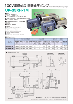
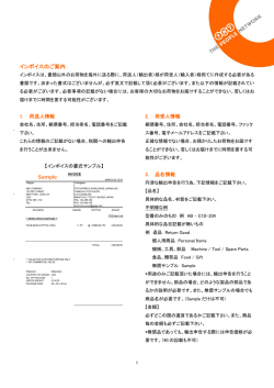
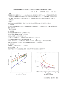
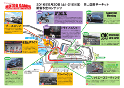
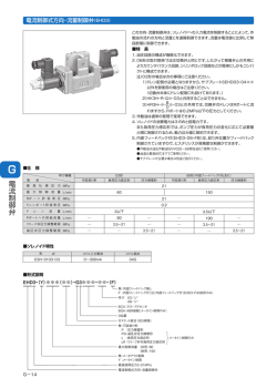
トロコイドポンプ
TROCHOID PUMP
製品名(Model 名)
Page
小容量
1A
1HG
(1 ∼ 8R/min)
Model 1 (Small capacity) 1ME
製品名(Model 名)
3 大容量
4AMVB
3 (116 ∼ 586R/min) 4A
3∼4 Model 4 (Large capacity) GPL
Trochoid pump integrated with 1ME motor
1ME(立て形)
1MBM(ベース・カップリング取付型) 4
Trochoid pump directly coupled with motor
(equipped with base coupling)
小・中容量
Model 2
(Small and intermediate
capacity)
2HB
2.5HGA
2MY
4MBM(ベース・カップリング取付型) 10
Trochoid pump directly coupled with motor
(equipped with base coupling)
正・逆回転可能
Reversible pump
5
5
5
Trochoid pump integrated with 2MY motor
燃料ポンプ
Fuel pump
2MBM(ベース・カップリング取付型) 6
Trochoid pump directly coupled with motor
(equipped with base coupling)
クリーンハット
(サクションフィルター付)
6
Trochoid pump integrated with Motor 2 equipped
with suction filter
クーラントポンプ
Coolant pump
2HWM
7
Special design HWM series trochoid pump
クリーンハット
(サクションフィルター付)7
Coolant pump with suction filter
(Element cleaning type)
中容量
(39 ∼ 117R/min)
Model 3
(Intermediate capacity)
N3H
N3F
3MF
Trochoid pump integrated with 3MF motor
3MBM(ベース・カップリング取付型) 9
Trochoid pump directly coupled with motor
(equipped with base coupling) Trochoid Pump is a registered trademark of Nippon Oil Pump Co.,Ltd.
濾過ポンプ
Filtration pump
1RA
2RA
3RD
11
11
11
GFS
GFY
GFKY
GFLY
GFH
GD
GFM
12
12
12
13
13
13
14
ミクロトップ
14
(ハンディタイプ小型油濾過装置)
Micro-top
リリーフバルブ
8
8
8
9
9
10
GPL lunary low-noise pump(External gear pump)
4
Trochoid pump integrated with 1ME motor
(vertical type) Model 2
(4 ∼ 36R/min)
Page
Relief valve
リリーフバルブTOP-VB,VBD
Relief valve TOP-VB, VBD
15
水ポンプ
WATER PUMP
製品名(Model 名)
Page
プロコンポンプ
16
(自吸式ロータリーベーン型水ポンプ)
Procon pump (self-priming type rotary vane
pump)
プロコンポンプ
17
Procon pump
ダイアフラムポンプ
17
製品名(Model 名)
減速機
Page
Planetary Reduction Gear
GRS-1
GRS-6
21
21
油圧制御バルブ
カウンタバランスバルブ(CBV)
21
Hydraulic control valve
Counterbalancing valve
クロスオーバーリリーフバルブ(COR) 21
Crossover relief valve
カウンターバランスブレーキバルブ(CBB)21
Counterbalancing brake valve
インデックスモータ HMI
lndexing motor
油圧モータ・関連機器
Page
オーブマークモータ M(小型油圧モータ)
M(small hydraulic motor)
S
メカニカルブレーキ付 Sシリーズモータ
S motor
モータ
GWM
Motor with mechanical
brake
22
22
HYDRAULIC MOTOR
製品名(Model 名)
Orbmark motor
EIS
18
18
19
19
GWM
PM-Oパワーモータ
20
Model PM-O power motor
PM-Bパワーモータ(メカニカルブレーキ付)20
Model PM-B power motor (with mechanical brake)
※詳しい仕様・形状については別途カタログをお取り寄せください。
*For detailed specifications and shape, call us for a separate catalog.
小容量トロコイドポンプ
TROCHOID PUMP
Model 1
1. 1A
1A Trochoid Pump
■ 仕 様
項目
ltem
SPECIFICATIONS
理 論
押し除け容積
TheoreticaI discharge
cm3/rev
1500min−1 1800min−1
TheoreticaI
displacement
型式
Model
Max.
pressure
1.2
2.2
3.7
6.7
1.4
2.7
4.5
8.1
最高回転数
Max.
revolution
概略質量
Approx.
weight
MPa
min−1
kg
0.5
0.5
0.5
0.5
3,000
2,000
1,800
1,800
0.5
0.5
0.6
0.8
最大圧力
最高回転数
概略質量
1HG Torochoid Pump
■ 仕 様
項目
ltem
型式
Model
SPECIFICATIONS
理 論
押し除け容積
TheoreticaI
displacement
cm3/rev
理論吐出量
TheoreticaI discharge
Max.
pressure
r/min
1500min−1 1800min−1
1.5
2.5
TOP-11HG
TOP-12HG
3. 1ME
最大圧力
r/min
0.8
1.5
2.5
4.5
TOP-10A
TOP-11A
TOP-12A
TOP-13A
2. 1HG
理論吐出量
2.2
3.7
2.7
4.5
Max.
revolution
Approx.
weight
MPa
min−1
kg
2.5
2.5
3,000
2,500
1.4
1.5
Trochoid Pump integrated with Motor 1
■ 仕 様
SPECIFICATIONS
項目
ltem
型式
Model
TOP-1ME75-1-10MA(VB)
TOP-1ME75-1-11MA(VB)
TOP-1ME75-1-12MA(VB)
1500min−1当り (50Hz)
1800min−1当り (60Hz)
理論吐出量
最大圧力
理論吐出量
最大圧力
r/min
MPa
r/min
MPa
kg
1.2
2.2
3.7
0.5
0.5
0.2
1.4
2.7
4.5
0.4
0.3
0.3
7.5
TheoreticaI
discharge
Max.
pressure
TheoreticaI
discharge
Max.
pressure
概略質量
(モータ)
Approx. weight
(motor)
■ モータ仕様
三相かご形誘導モータ・E 種絶縁・全閉形
AC200V/50, 60Hz・AC220/60Hz
4 極・連続定格・75W
※単相電源(100V)もございます。 出力 75W
■MOTOR SPEllFICATIONS
3-phase induction motor, class E insulation, totally enclosed 200VAC, 50/60Hz or 220VAC,
60Hz 4 poles with continuous rating at 75W
※The pump with a single phase power supply( 100V)is also availabIe. Output:75W
3
小容量トロコイドポンプ
TROCHOID PUMP
Model 1
4. 1ME
Trochoid pump integrated with 1ME motor
■ 仕 様
SPECIFICATIONS
項目
1500min−1当り (50Hz)
1800min−1当り (60Hz)
理論吐出量
最大圧力
理論吐出量
最大圧力
r/min
MPa
r/min
MPa
kg
TOP-1ME100(200)-10MA(VB)
TOP-1ME100(200)-11MA(VB)
1.2
2.2
0.5
0.5
1.4
2.7
TOP-1ME100(200)-12MA(VB)
3.7
0.5
4.5
100W=8.0
200W=9.0
TOP-1ME100(200)-13MA(VB)
6.7
100W=0.2
200W=0.5
8.1
0.5
0.5
100W=0.3
200W=0.5
100W=0.1
200W=0.5
ltem
TheoreticaI
discharge
型式
Model
Max.
pressure
TheoreticaI
discharge
Max.
pressure
概略質量
(モータ)
Approx. weight
(motor)
■ モータ仕様
三相かご形誘導モータ・E種絶縁・全閉形・AC200V/50, 60Hz・AC220/60Hz
4 極・連続定格・100W・200W
※単相電源(100V)もございます。出力 200W
■MOTOR SPEllFICATIONS
3-phase induction motor, class E insulation, totally enclosed 200VAC, 50/60Hz or 220VAC,
60Hz
4 poles with continuous rating at 100W 200W
※The pump with a single phase power supply
( 100V)is also availabIe. Output:200W
5. 1ME 立て形 2 型
型式:TOP-1ME75-2-1MA
Trochoid Pump integrated with 1ME motor(vertical type), Model 2
■ 仕 様
SPECIFICATIONS
MODEL:TOP-1 ME75-2-1 MA
項目
ltem
1500min−1当り (50Hz)
Model
TOP-1ME75-2-10MA(VB)
TOP-1ME75-2-11MA(VB)
TOP-1ME75-2-12MA(VB)
概略質量
(モータ)
理論吐出量
最大圧力
理論吐出量
最大圧力
r/min
MPa
r/min
MPa
kg
1.2
2.2
3.7
0.5
0.5
0.2
1.4
2.7
4.5
0.4
0.3
0.1
8.0
TheoreticaI
discharge
型式
1800min−1当り (60Hz)
Max.
pressure
TheoreticaI
discharge
Max.
pressure
Approx. weight
(motor)
■ モータ仕様
三相かご形誘導モータ・E 種絶縁・全閉形
AC200V/50, 60Hz・AC220/60Hz
4 極・連続定格・75W
2型
■MOTOR SPEllFICATIONS
3-phase induction motor, class E insulation, totally enclosed 200VAC, 50/60Hz or 220VAC,
60Hz
4 poles with continuous rating at 75W
6. 1MBM(ベース・カップリング取付型)
■ 仕 様
Trochoid pump directly coupled with motor(equipped with base coupling)
SPECIFICATIONS
項目
理論吐出量
ltem
型式
Model
TheoreticaI discharge
1500min−1
2.2
3.7
TOP-11HG
TOP-12HG
モータ対応
口径
r/min
1800min−1
2.7
4.5
Pipe
Diameter
Rc 1/4
Rc 1/4
200, 400 (W)
Compatible motor:200 and 400( W)
4
小・中容量トロコイドポンプ
TROCHOID PUMP
Model 2
7.
2HB
2HB Trochoid pump
■ 仕 様
SPECIFICATIONS
項目
理 論
押し除け容積
ltem
2.8
4
6
8
10
12
16
20
TOP-203HB
TOP-204HB
TOP-206HB
TOP-208HB
TOP-210HB
TOP-212HB
TOP-216HB
TOP-220HB
2.5HGA
1500min
cm3/rev
Model
−1
Max.
pressure
1800min
−1
4.2
6.0
9.0
12.0
15.0
18.0
24.0
30.0
5.0
7.2
10.8
14.4
18.0
21.6
28.8
36.0
概略質量
最高回転数
最大圧力
r/min
TheoreticaI
displacement
型式
8.
理論吐出量
TheoreticaI discharge
Approx.
weight
Max.
revolution
MPa
min
3.0
3.0
2.5
2.5
2.5
2.0
1.5
1.2
kg
−1
3,000
3,000
2,500
2,500
2,500
2,000
1,800
1,800
3.5
3.6
3.8
4.0
4.1
4.3
4.6
5.0
2.5HGA Trochoid pump
● 2HB、N3F・Hの中間機種として開発された機種で高速回転でも、騒音の発生があ
りません。
リリーフバルブはポンプ上部に取付けられます。
3VBが共通で使用できる設計になっ
ております。
●This pump has been developed as an intermediate model between Model 2 and Model 3.
It does
not produce noise even during operation at a high speed.
The relief valve is installed on the top of the pump.
It is designed to allow shared use of the 3VB.
■ 仕 様
SPECIFICATIONS
項目
理 論
押し除け容積
ltem
TheoreticaI
displacement
型式
Model
cm3/rev
2MY
最大圧力
Max.
pressure
最高回転数
概略質量
r/min
1500min−1 1800min−1
MPa
min−1
kg
2.5
2.0
2,500
2,000
7.0
7.0
16
20
TOP-2516HGA
TOP-2520HGA
9.
理論吐出量
TheoreticaI discharge
24
30
28.8
36.0
Approx.
weight
Max.
revolution
Trochoid pump integrated with 2MY motor
TOP-2MY ※※※ -2 ※※ HBMVB
■ 仕 様
SPECIFICATIONS
項目
型式
ltem
Model
理 論
吐出量
TheoreticaI
discharge
50Hz (1500min−1)
モータ出力に対する最大圧力
Max.pressure for motor output
MPa
理 論
吐出量
TheoreticaI
discharge
60Hz (1800min−1)
モータ出力に対する最大圧力
Max.pressure for motor output
MPa
r/min 200W 400W 750W 1500W r/min 200W 400W 750W 1500W
TOP-203HBM
TOP-204HBM
TOP-206HBM
TOP-208HBM
TOP-210HBM
TOP-212HBM
TOP-216HBM
TOP-220HBM
4.2
6.0
9.0
12.0
15.0
18.0
24.0
30.0
1.7
1.2
0.7
0.5
0.4
0.3
0.2
3.0
3.0
1.8
1.3
1.1
0.9
0.7
0.4
3.0
3.0
2.5
2.5
2.5
2.0
1.5
1.2
3.0
3.0
2.5
2.5
2.5
2.0
1.5
1.2
5.0
7.2
10.8
14.4
18.0
21.6
28.8
36.0
1.3
0.9
0.5
0.3
0.3
3.0
2.3
1.4
1.0
0.9
0.7
0.5
0.3
3.0
3.0
2.5
2.3
2.0
1.6
1.2
0.9
3.0
3.0
2.5
2.5
2.5
2.0
1.5
1.2
■ モータ仕様
For the details of special motor specifications, please
contact our sales office.
※ The pump with a single phase power supply (100V,
200V) is also available.
output type : 200 400 750W
三相かご形誘導モータ・E 種絶縁・全閉外扇形
AC200V/50, 60Hz・AC220V/60Hz・4 極・連続定格
出力の種類:200, 400, 750, 1500 (W)
特殊モータ仕様についてはお問合せください。
※単相電源(100V, 200V)もございます。出力 200, 400, 750W
■MOTOR SPECIFICATlONS
3-phase induction motor, class E insulation, totally enclosed fan-cooled squirrel cage type 200VAC,
50/60Hz or 220VAC, 60Hz 4 poles with continuous rating
Output type: 200, 400, 750, 1500W
5
小・中容量トロコイドポンプ
TROCHOID PUMP
Model 2
10. 2MBM(ベースカップリング取付型)Trochoid pump directly coupled with motor (equipped with base coupling)
TOP-2MBM ※※※ -2 ※※ HBVB
■ 仕 様
SPECIFICATIONS
理論吐出量
項目
口径
TheoreticaI discharge
ltem
r/min
型式
1500min
−1
Model
TOP-203HB
4.2
TOP-204HB
6.0
TOP-206HB
9.0
TOP-208HB
12.0
TOP-210HB
15.0
TOP-212HB
18.0
TOP-216HB
24.0
TOP-220HB
30.0
モータ対応
200, 400, 750, 1500 , 2200(W)
Pipe
Diameter
1800min
−1
5
7.2
10.8
14.4
18.0
21.6
28.8
36.0
Rc 1/2
Rc 3/4
compatible motor: 200,400,750,1500,2200w
11. クリーンハット(サクションフィルター付)Trochoid pump integrated with 2MY motor equipped with suction filte
TOP-2MY ※※※ -2 ※※ HBMPVBE
(エレメント洗浄タイプ)
(Element cleaning type)
■ 仕 様
SPECIFICATIONS
項目
ltem
型式
Model
203HBMPVBE
204HBMPVBE
206HBMPVBE
208HBMPVBE
210HBMPVBE
理論吐出量
TheoreticaI discharge
r/min
1500min−1
1800min−1
4.2
6.0
9.0
12.0
15.0
5.0
7.2
10.8
14.4
18.0
吸入口径
Suction port
diameter
吐出口径
Discharge port
diameter
Rc 1/2
Rc 1/2
Rc 3/4
■ モータ仕様
三相かご形誘導モータ・E 種絶縁・全閉外扇形
AC200V/50, 60Hz・AC220V/60Hz・4 極・連続定格
出力の種類:200, 400, 750, 1500 (W)
※単相電源(100V, 200V)もございます。出力 200, 400, 750W
■MOTOR SPECIFICATlONS
3-phase induction motor, class E insulation, totally enclosed fan-cooled squirrel cage type
200VAC, 50/60Hz or 220VAC, 60Hz 4 poles with continuous rating
Output type: 200, 400, 750, 1500W
TOP-2MY ※※※ -2 ※※ HBMPVB
(カートリッジ交換タイプ)
■ 仕 様
SPECIFICATIONS
項目
(Cartridge replacement type)
ltem
型式
Model
203HBMPVB
204HBMPVB
206HBMPVB
208HBMPVB
210HBMPVB
理論吐出量
TheoreticaI discharge
r/min
1500min−1
1800min−1
4.2
6.0
9.0
12.0
15.0
5.0
7.2
10.8
14.4
18.0
吸入口径
Suction port
diameter
吐出口径
Discharge port
diameter
Rc 1/2
Rc 1/2
Rc 3/4
■ モータ仕様
三相かご形誘導モータ・E 種絶縁・全閉外扇形
AC200V/50, 60Hz・AC220V/60Hz・4 極・連続定格
出力の種類:200, 400, 750, 1500 (W)
※単相電源(100V, 200V)もございます。出力 200, 400, 750W
■MOTOR SPECIFICATlONS
3-phase induction motor, class E insulation, totally enclosed fan-cooled squirrel cage type
200VAC, 50/60Hz or 220VAC, 60Hz 4 poles with continuous rating
Output type: 200, 400, 750, 1500W
※The pump with a single phase power supply (100V,200V) is also available.Output: 200, 400, 750W
6
クーラントポンプ
TROCHOID PUMP
Coolant pump
12. 2HWM
Special design HWM series trochoid pump
TOP-2MY ※※※ -2 ※※ HWMVB
■ 仕 様
SPECIFICATIONS
項目
50 Hz (1500min−1)
ltem
理 論
吐出量
TheoreticaI
discharge
型式
60 Hz (1800min−1)
モータ出力に対する最大圧力
Max. pressure for motor output
MPa
理 論
吐出量
モータ出力に対する最大圧力
Max. pressure for motor output
TheoreticaI
discharge
MPa
r/min 200W 400W 750W 1500W r/min 200W 400W 750W 1500W
Model
6.0
9.0
12.0
15.0
18.0
24.0
30.0
TOP-204HWM
TOP-206HWM
TOP-208HWM
TOP-210HWM
TOP-212HWM
TOP-216HWM
TOP-220HWM
1.2
0.8
0.6
0.4
0.3
0.2
2.0
1.8
1.4
1.2
1.0
0.8
0.6
2.0
2.0
2.0
2.0
2.0
1.5
1.2
2.0
2.0
2.0
2.0
2.0
2.0
1.5
7.2
10.8
14.4
18.0
21.6
28.8
36.0
1.0
0.6
0.4
0.3
2.0
1.6
1.2
1.0
0.8
0.6
0.5
2.0
2.0
2.0
2.0
1.6
1.2
1.0
2.0
2.0
2.0
2.0
2.0
2.0
1.5
(試験液:JIS W1 種 2 号 20 倍希釈)
(Test solution:JIS W1 class No.
2 diluted in water to a ratio of 1 to 20)
■ 特 長
■FEATURES
●Designed in a special structure for use with coolant
This coolant pump is designed to ensure excellent durability against coolant
because special design considerations are given to each part of the pump.
● クーラント用特殊構造になっています。
クーラント用ポンプとして各部に特別な設計配慮がされています
ので、切削液での使用に耐えられます。
●High operating pressure
The pump can be used at the pressure up to 1.5∼2.0MPa. Powerful jet from
the high pressure nozzle removes cutting chips and cooIs blades effectively.
● 使用圧力が高い
最大1.5∼2.0MPaまでの圧力で使用可能、高圧ノズルより
の噴射により強力に切粉除去と冷却ができます。
●Self-priming structure
While the conventional impeller pump is not self-priming and needs to be
submerged in the tank or primed, the HWM trochoid pump is designed in a
self-priming structure to eliminate such burdensome requirements.
● 自吸形です。
従来のインペラーポンプは自吸性がないために、タンク内に
浸漬したり、呼び水を必要とした条件付きでしたが“HWM”
タイプのトロコイドポンプは自吸性なので手がかかりません。
■MOTOR SPECIFICATIONS
3-phase induction motor, class E insulation, totally enclosed fancooled squirrel
cage type
200VAC, 50/60Hz or 220VAC, 60Hz, 4 poles with continuous rating
Output type: 200, 400, 750, 1500W
※The pump with a single phase power supply (100V, 200V) is also available.
Output: 200, 400, 750W
※We also provide the pump equipped with a suction filter. (See Page 6)
■ モータ仕様
三相かご形誘導モータ・E 種絶縁・全閉外扇形
AC200V/50, 60Hz・AC220V/60Hz・4 極・連続定格
出力の種類:200, 400, 750, 1500 (W)
※単相電源(100V, 200V)もございます。出力200, 400, 750W
※サクションフィルタ付にする事も可能です。(P6 参照)
13. クリーンハット(サクションフィルター付) Coolant pump with suction filter
TOP-2MY ※※※ -2 ※※ HWNPEVB
(エレメント洗浄タイプ)
■ 仕 様
SPECIFICATIONS
項目
ltem
型式
Model
TOP-212HWNPEVB
TOP-216HWNPEVB
TOP-220HWNPEVB
50 Hz (1500min−1)
60 Hz (1800min−1)
理 論
吐出量
Max. pressure for motor output
r/min
400W
18.0
24.0
30.0
1.0
0.8
0.6
TheoreticaI
discharge
モータ出力に対する最大圧力
MPa
理 論
吐出量
TheoreticaI
discharge
750W 1500W r/min
2.0
1.5
1.2
2.0
2.0
1.5
モータ出力に対する最大圧力
Max. pressure for motor output
MPa
400W
21.6
28.8
36.0
0.8
0.6
0.5
750W 1500W
1.6
1.2
1.0
2.0
2.0
1.5
■ モータ仕様
三相かご形誘導モータ・E 種絶縁・全閉外扇形
AC200V/50, 60Hz・AC220V/60Hz・4 極・連続定格
出力の種類:400, 750, 1500 (W)
※単相電源(100V, 200V)もございます。出力 400, 750W
2HWNPE
■MOTOR SPECIFICATIONS
3-phase induction motor, class E insulation, totally enclosed fan- cooled squirrel cage type
200VAC, 50/60Hz or 220VAC, 60Hz, 4 poles with continuous rat ing
Output type: 400, 750, 1500W
※ The pump with a single phase power supply (100V, 200V) is also available.
Output: 400, 750W
7
中容量トロコイドポンプ
TROCHOID PUMP
Model 3
14. N3H
N3H trochoid pump
■ 仕 様
SPECIFICATIONS
項目
ltem
理論押し
除け容積
理論吐出量
TheoreticaI discharge
TheoreticaI
displacement
型式
cm3/rev
Model
r/min
1500min−1 1800min−1
26.0
39.0
52.0
65.0
TOP-N320H
TOP-N330H
TOP-N340H
TOP-N350H
39.0
58.5
78.0
97.5
46.8
70.2
93.6
117.0
最大圧力
口径
最 高
回転数
Diameter
Max.
pressure
Max.
revolution
MPa
min − 1
4.0
* 4.0
* 3.0
* 2.0
1,800
1,800
1,800
1,800
Rc
概略質量
Approx.
weight
吸 入
吐 出
del
kg
1
1 1/4
1 1/4
1 1/4
1
1
1
1
14.8
14.9
14.9
15.6
suc
* 印の仕様にてご使用の際はご相談ください。
*Please contact us when you want to use the pump based on the specifications marked with asterisks.
15. N3F
N3F trochoid pump
■ 仕 様
SPECIFICATIONS
項目
ltem
理 論
押し除け容積
TheoreticaI discharge
最大圧力
Max.
pressure
最高回転数
概略質量
r/min
cm3/rev
1500min−1 1800min−1
MPa
min−1
kg
TheoreticaI
displacement
型式
Model
FA
TOP-N320 FA VB
FB
FA
TOP-N330 FA VB
FB
FA
TOP-N340 FA VB
FB
(写真は FAVB 型です)
(Photo shows Model FAVB).
16. 3MF
理論吐出量
Max.
revolution
26
39.0
46.8
2.5
1,800
39
58.5
70.2
* 2.5
1,800
52
78.0
93.6
* 2.0
1,800
Approx.
weight
8.0
10.5
9.0
8.0
10.5
9.0
8.0
10.5
9.0
*印の仕様にてご使用の際はご相談ください。
*Please contact us when you want to use the pump based on the specifications marked with asterisks.
Trochoid pump integrated with 3MF motor
TOP-3MF ※※※ -N3 ※※ FAVB
■ 仕 様
SPECIFICATIONS
項目
ltem
型式
Model
TOP-3MF- *** -N320F
TOP-3MF- *** -N330F
TOP-3MF- *** -N340F
50Hz
1500min−1
60Hz
1800min−1
理論
モータ出力に対する最大圧力
Max. pressure for motor output 吐出量 Max. pressure for motor output
TheoreticaI
TheoreticaI
MPa
MPa
理論
吐出量
モータ出力に対する最大圧力
discharge
discharge
r/min 750W 1500W 2200W r/min
39.0
58.5
78.0
0.4
0.1
1.3
0.8
0.5
2.1
1.3
0.9
46.8
70.2
93.6
750W 1500W 2200W
0.2
1.0
0.6
0.3
1.7
1.0
0.6
◎ ポンプ型式の***部分にご希望W数を入れてモータ指定してください。
◎ Describe your desired watt in the asterisked portion (***) for model designation to specify the
motor.
8
中容量トロコイドポンプ/大容量トロコイドポンプ
TROCHOID PUMP
Model 3 / Model 4
17. 3MBM(ベース・カップリング取付型)Trochoid pump directly coupled with motor (equipped with base coupling)
TOP-3MBM ※※※ -N3 ※※ HVB
■ 仕 様
SPECIFICATIONS
口径
理論吐出量
項目
Diameter
TheoreticaI discharge
ltem
Rc
r/min
型式
1500min
−1
Model
39.0
58.5
78.0
97.5
TOP-N320H
TOP-N330H
TOP-N340H
TOP-N350H
吸入
1800min
−1
吐出
Suction
Discharger
Rc 1
46.8
70.2
93.6
117.0
Rc 1/4
Rc 1
モータ対応
1.5kW, 2.2kW, 3.7kW..... 特殊モータ(安全増防爆型・耐圧防爆型 etc.)取付可能です。
TOP-3MB-N3H
18. 4AM
Compatible motor
The pump can be provided with a special motor (explosion proof structure with additional safety)
with the output of 1.5kW, 2.2kW and 3.7kW.
4AM trochoid pump
■ 仕 様
SPECIFICATIONS
項目
ltem
型式
Model
19. 4A
r/min
Max.
pressure
cm /rev
1000min−1
MPa
116
148
116
148
最大圧力
最高回転数
Max.
revolution
概略質量
Approx.
weight
−1
min
kg
2.0
2.0
1,800
1,800
31
33
概略質量
4A trochoid pump
■ 仕 様
SPECIFICATIONS
項目
ltem
型式
Model
TOP-4300AVB
TOP-4500AVB
9
TheoreticaI discharge
TheoreticaI
displacement
3
TOP-4100AMVB
TOP-4130AMVB
理論吐出量
理 論
押し除け容積
理論吐出量
理 論
押し除け容積
TheoreticaI discharge
最大圧力
Max.
pressure
最高回転数
r/min
cm3/rev
1000min−1
MPa
min−1
kg
352
586
352
586
1.0
1.0
1,200
1,200
120
125
TheoreticaI
displacement
Max.
revolution
Approx.
weight
大容量トロコイドポンプ
TROCHOID PUMP
Model 4
20. GPL
GPL lunary low-noise pump(external gear pump)
ルーナリーギアポンプ
■ 構 造
このポンプにはルーナリー® (特許)と呼ばれる歯形をもった歯車が使用されてお
り、連続一点接触で回転いたします。
従来の連続一点接触歯車(欠円歯車、サイン曲線歯車等)は、理論的カーブを修正
したり、組み合わせたりしているため、どうしてもすべり率が大きくなりがちです
が、
ルーナリーギアは理論的な直線と楕円により理想的な閉曲線が得られますので、
すべり率の少ない耐久力のあるポンプとなっております。
■ 特 長
(I)
閉込みがないため脈動、騒音が非常に少ない。
(II) キャビテーション現象がないので高粘度油の使用に適している。
(III) 特許ルーナリーギア使用のため耐久力がある。
(IV) 軸入力が少なく、経済的である。
(写真はイケール付)
(The photo shows an angle plate)
Patented Lunary gear pump
●STRUCTURE
This pump by the name of Lunary (R) (patented) uses a gear having teeth, and rotates in conformity
to continuous one-point contact. The conventional one-point contact gear (segmental gear, sinusoidal
gear, etc.) is based on correction or combination of the theo retical curve, so the slippage ratio tends
to increase. However, the Lunary gear provides a highly durable pump with small slippage ratio
because an ideal closed curve is gained from a theoretical straight line and ellipse.
●FEATURES
(1) Pulsation and noise are extremely limited due to lack of confinement.
(2) This pump is effectively used with highly viscous oil because there is no cavitation.
(3) Durability is provided by a patented Lunary gear.
(4) Use of a shaft input is eliminated to cut down costs.
■ 仕 様
項目
ltem
型式
Model
SPECIFICATIONS
最大圧力
理論押し
除け容積
TheoreticaI discharge
Pressure
cm3/rev
1000min−1 1200min−1
Normal
TheoreticaI
displacement
150
200
250
GPL-150
GPL-200
GPL-250
理論吐出量
r/min
150
200
250
MPa
180
240
300
1.0
1.0
1.0
*印の仕様にてご使用の際はご相談ください。
潤滑性のある油でご使用ください。(粘度 46 ∼ 2,000mm2/s)
*Please contact us when you want to use the pump based on the specifications marked with asterisks.
*Use lubricating oil to operate the pump.(Viscosity: 46 to 2,000mm2/s)
21. 4MB(ベース・カップリング取付型)Trochoid pump directly coupled with motor (equipped with base coupling)
TOP-4MB ※※※※ -4 ※※※ AMIVB
■ 仕 様
SPECIFICATIONS
項目
ltem
型式
Model
1000 min−1の
定格理論吐出量
TheoreticaI displacement
of 1000min-1
r/min
吸入・吐出口径
Suction and
discharge port
diameter
TOP-4100AMVB
116
Rc1 1/2
TOP-4130AMVB
148
Rc2
TOP-4150AMVB
172
Rc2
TOP-4200AMVB
231
Rc2
TOP-4250AMVB
281
Rc2
この他に 4A・GPL もベース・カップリング取付型にすることも可能です。
Further, the 4A.GPL directly coupled with motor is also available.
10
正・逆回転可能トロコイドポンプ
TROCHOID PUMP
Reversible trochoid pump
■ 特 長
左・右どちらに回転させても
正・逆回転可能トロコイドポンプは、正逆いずれの方向に回転しても、
油の流れは常に
一方方向に流れます
吸入口、吐出口は一定であるように設計されたものです。
Independently of whether
the pump is turned in
forward or reverse direction,
oil flows only in one direction
at all times.
■FEATURES
The reversible trochoid pump is designed to ensure the suction port and discharge
port remain unchanged independently of whether it is turned in forward or reverse
direction.
22. 1RA
1RA reversible pump
■ 仕 様
項目
ltem
Model
cm3/rev
最大圧力
Max.
pressure
最高回転数
概略質量
r/min
1500min−1 1800min−1
MPa
min−1
kg
Max.
revolution
Approx.
weight
1.16
1.74
2.08
0.5
2,000
1.1
TOP-1RA-200
TOP-1RA-300
1.80
2.50
2.70
3.75
3.24
4.50
0.5
0.5
2,000
2,000
1.2
1.3
2RA reversible pump
項目
ltem
SPECIFICATIONS
理 論
押し除け容積
TheoreticaI
displacement
型式
Model
cm3/rev
TOP-2RA-4C
TOP-2RA-8C
TOP-2RA-12C
理論吐出量
最大圧力
Max.
pressure
最高回転数
概略質量
r/min
1500min−1 1800min−1
MPa
min−1
kg
0.5
0.5
0.5
2,000
2,000
1,800
3.5
4.0
4.5
最大圧力
最高回転数
概略質量
MPa
min−1
kg
0.5
0.5
0.5
0.5
0.5
1.800
1,800
1,800
1,800
1,800
10.0
10.0
10.5
11.0
11.5
TheoreticaI discharge
4.0
8.0
12.0
6.0
12.0
18.0
7.2
14.4
21.6
Max.
revolution
Approx.
weight
3RD reversible pump
■ 仕 様
項目
ltem
型式
Model
TOP-3RD-10T
TOP-3RD-15T
TOP-3RD-20T
TOP-3RD-25T
TOP-3RD-30T
11
理論吐出量
TheoreticaI discharge
TOP-1RA-100
■ 仕 様
24. 3RD
理 論
押し除け容積
TheoreticaI
displacement
型式
23. 2RA
SPECIFICATIONS
SPECIFICATIONS
理 論
押し除け容積
TheoreticaI
displacement
cm3/rev
13.0
19.5
26.0
32.5
39.0
理論吐出量
TheoreticaI discharge
r/min
1,000min−1 1,200min−1
13.0
19.5
26.0
32.5
39.0
15.6
23.4
31.2
29.0
46.8
Max.
pressure
Max.
revolution
Approx.
weight
燃料ポンプ
TROCHOID PUMP
Fuel pump
25. GFS
Fuel pump GFS type
灯油、A 重油用
● 小型バーナ用に特別に設計・製作致しました。
● 2ッ孔フランジ付(GFS-A)およびフランジ無しセットスクリュー取付型の2機種あ
りますので、各バーナに最適のポンプをお選び下さい。他にカットオフバルブを取
外した安価な GFS-D もあります。
● サビ、スケール等によるバルブのトラブルを無くすためにバルブ構造は従来の概念
を打ち破ったユニークな構造とし(PAT 申請中)安心してご使用戴けます。
● 起動トルクは最大でも 10N・m 以下であり、経済的な小型モータが採用できます。
For kerosine and heavy oil A
●Designed and manufactured specifically for small-sized burners.
●The pump is available in two types; one is provided with two-hole flange (GFS-A) and the other is
designed as a set screw installation type without flange. You can select the optimum pump to meet
your burner requirements. We also manufacture a less expensive GFS-D pump without cut-off valve.
●The valve is designed in aunique structure based on an entirely new engineering concept to
protect against rust and scale (patent pending). This will ensure reliable pump operations.
●The maximum starting torque does not exceed 10 N.m. An economical small-sized motor can be
adopted.
■ 仕 様
型 式
Type
GFS
26. GFY
灯油の場合
SPECIFICATIONS
(for kerosine)
圧力 MPa
Pressure
吐出容量(r/h)
Discharge capacity
(2,900min−1)
0.7 ∼ 1.2
35 ∼ 20
Fuel pump GFY type
灯油、A 重油用
● 吐出容量区分では、3 種類ですが、現在シャフト形状その他、特殊型も含めて 9 種
類取り揃えました。用途によりご相談ください。
● 潤滑性にとぼしい日本の灯油に合わせた設計で、耐久力に富んだスペシャルマテリ
アルを採用しておりますので、寿命は絶大であります。
For kerosine and heavy oil A
●ln terms of discharge capacity, this pump is available in three types. Currently, however, a total of
nine types including special pumps are available; they are classified according to shaft form and
other factors. Consult us to choose the one best suited to your needs.
●The product is designed to meet the Japanese kerosine which is poorer in lubrication properties.
lt is made of special materials featuring excellent durability, thereby ensuring a very long service
life.
■ 仕 様
型 式
Type
GFY
27. GFKY
灯油の場合
SPECIFICATIONS
(for kerosine)
圧力 MPa
Pressure
吐出容量(r/h)
Discharge capacity
(2,900min−1)
0.7 ∼ 1.4
100 ∼ 25
Fuel pump GFK type
灯油、A 重油用
● 吐出容量区分では 2 種類で、GFY と同じ使用条件で、容量のみ一回り上のご使用に
適当なポンプです。
For kerosine and heavy oil A
●ln terms of discharge capacity, this pump is available in two types.
This pump is used under the same conditions as those of the GFY with a capacity one size greater
than that of the GFKY.
■ 仕 様
型 式
Type
GFKY
灯油の場合
SPECIFICATIONS
(for kerosine)
圧力 MPa
Pressure
0.7 ∼ 2.0
吐出容量(r/h)
Discharge capacity
(2,900min−1)
180 ∼ 110
12
燃料ポンプ
TROCHOID PUMP
Fuel pump
28. GFLY
Fuel pump GFL type
灯油、A 重油用
● 吐出容量区分で 3 種類製作しております。
● 公害防止による重油規制のため開発されたポンプで、非常に条件の悪い日本の灯油
を使用しても、2.0MPa の高圧に耐えうるように 2 ステージ型を採用し、日本の灯
油を使用しては、世界最高の信頼性を誇る軽粘度燃料用大容量ポンプです。
GFLY for kerosine and heavy oil A
● In terms of discharge capacity, this pump is available in three types.
●This pump has been developed to meet heavy oil pollution control requirements. This product is
designed in a two-stage structure to withstand 2.0 MPa high pressure even when Japanese kerosine
under very unfavorable conditions is used. It is a large-capacity pump for low viscosity boasting the
world’
s highest reliability when Japanese kerosine is used.
■ 仕 様
灯油の場合
型 式
圧力 MPa
Type
Pressure
0.7 ∼ 2.0
GFLY
29. GFH
SPECIFICATIONS(for kerosine)
吐出容量(r/h)
Discharge capacity
(2,900min−1)
450 ∼ 200
Fuel pump GFH type
B・C 重油用
● 吐出容量区分で 20r/h(1,450min − 1 1.5MPa)から 230r/h (2,900min − 1
1.5MPa) 1.5MPa までの 4 種類ですが、現在シャフト形状が異なる機種を含め 7
種類製作しております。
For heavy oils B and C
● In terms of discharge capacity, this pump is available in four types ranging from 20L/h
(1,450min-1. 1.5 MPa) to 230L/h (2,900min-1. 1.5 MPa). Currently, however, a total of seven types
including those different in shaft forms are available.
■ 仕 様
型 式
Type
GFH
30. GD
灯油の場合
SPECIFICATIONS(for kerosine)
圧力 MPa
Pressure
1.0 ∼ 2.5
吐出容量(r/h)
Discharge capacity
(2,900min−1)
230 ∼ 40
Fuel pump GD type
灯油、A・B・C 重油用
● 吐出量区分で重油用、灯油用各 6 種類(202 型、203 型、204 型、206 型、208
型、210 型)を製作しております。
● 高圧(重油4.0MPa、灯油2.0MPa)大容量(灯油60r/h∼760r/h、重油125r/
h∼860r/h)にて重油または灯油使用に充分耐えうるポンプという目的のために
2 ステージ型となっております。
● 調圧は、工具なして簡単に調整できるように設計されております。
● 灯油用と重油用は材質が違いますので、共用はできません。
For Kerosine heavy oils A, B and C
● ln terms of discharge capacity, this pump is available in six types for heavy and kerosine oils
(Models 202, 203, 204, 206, 208 and 210).
●The pump is designed as a two-stage structure to withstand use of heavy oil and kerosine at a
high pressure (4.0 MPa for heavy oil and 2.0 MPa for kerosine) and a large capacity (60 to 760 L/h
for kerosine and 125 to 860 L/h for heavy oil).
● The product is designed to permit easy adjustment of pressure without tool.
● Different materials are used in the pumps for kerosine and heavy oil, and they cannot be used in
common.
■ 仕 様
型 式
Type
GD
13
灯油の場合
SPECIFICATIONS
(for kerosine)
圧力 MPa
Pressure
0 ∼ 2.0
吐出容量(r/h)
Discharge capacity
(1,450min−1)
760 ∼ 60
リリーフバルブ
TROCHOID PUMP
Relief valve
33. TOP-VB、VBD
Relief valve TOP-VB, VBD
油圧回路内の圧力が、弁の設定値に達すると、弁が開いて、油の一部または全量を戻り
側へ逃し、回路圧力を一定にしたり、最高圧力を規制してポンプや装置を保護する役目
を果たします。
容量及び設定圧力により 2 ∼ 4VBP (D)まで取り揃えてあります。
When pressure inside the hydraulic circuit has reached the valve set value, the valve opens to
relieve part of whole of oil to the return side, thereby keeping the circuit pressure constant. Or it is
intended to control the maximum pressure, thereby protecting the pump and equipment.
2VBD
Relief valves are available in a range from 2 to 4 VBP(D) according to the
capacity and set pressure.
■ リリーフバルブの種類
TYPE OF RELIEF VALVES
シリーズ
項目
2
3
4
2VB
3VB
4VBP
2VBD
3VBD
4VBPD
2VD
―
―
0.08 ∼ 2.5
0.08 ∼ 3.0
0.15 ∼ 2.0
36
100
200
Series
Item
① 油移送等・瞬間的に圧力を下げる 安全弁
としての使用法
Used as a safety valve for temporary
pressure reduction, for example, in oil
feed
② 油圧(叉は強制循環給油)用圧力調整弁
としての使用法(サブプレート付)
Used as a pressure requlating valve for
hydraulic pressure (or lubrication of forced
circulation)(equipped with sub-plate)
③ 強制循環給油(叉は油圧)用圧力調整弁
としての使用法(サブプレート無し)
3VBD
Used as a pressure requlating valve for
lubrication of forced circulation (or
hydraulic pressure)(without sub-plate)
④ 圧力調整範囲
MPa
pressure control range (MPa)
⑤ 流 量 (Max)
r/min
Flow rate (MAX)
■ リリーフバルブ回路図及び設置方法
●RELIEF VALVE CIRCUIT DIAGRAM AND INSTALLATION METHOD
4VBPD
VB 型
VBD 型
VD 型
Model VB
Model VBD
Model VD
ポンプに直接取付ます。
回路上に設置します。
ポンプに直接取付ます。
(2VD のみとなります)
Installed directly on the
pump
15
Installed on the circuit
Installed directly on the pump
(only 2VD)
水ポンプ
WATER PUMP
Water pump Procon pump
34. プロコンポンプ(自吸式ロータリーベーン型水ポンプ)
Procon pump (self-priming type rotary vane pump)
小型・高圧(1.4MPa)
Compact configuration and high pressure
(1.4 MPa)
モータ付
With motor
■ 1450min − 1 (50Hz)における標準吐出量と所要動力
●Standard discharge rate and required power at 1450min-1. (50 Hz)
仕 様
所要動力 W
吐出量 r/min
Specifications
型 式
Discharge rate
Required power
圧力 MPa
圧力 MPa
Pressure
Model
1504
1507
1508
1509
1510
1505
1522
1521
1604
1607
1608
1609
1610
1605
1622
1621
0.35
5.14
4.24
3.77
3.29
2.71
1.96
1.33
0.80
2507
2506
2505
2504
2503
2502
2607
2606
2605
2604
2603
2602
13.0
11.9
10.4
9.2
7.6
6.4
Pressure
0.7
5.09
4.19
3.71
3.18
2.65
1.91
1.33
0.74
1.05
5.04
4.14
3.63
3.10
2.57
1.80
1.24
0.69
1.4
4.98
4.08
3.55
3.02
2.49
1.70
1.17
0.64
0.35
79
73
67
69
59
53
40
26
0.7
122
119
112
106
98
95
84
62
1.05
176
159
152
146
138
127
118
98
1.4
215
208
199
187
180
171
157
137
12.9
11.7
10.2
9.0
7.5
6.1
12.7
11.5
10.1
8.8
7.4
6.1
12.5
11.4
10.0
8.7
7.2
6.0
137
131
122
117
106
100
233
232
213
201
185
168
352
333
308
287
265
244
455
437
404
376
338
320
■ 1725min − 1 (60Hz)における標準吐出量と所要動力
●Standard discharge rate and required power at 1725min-1. (60 Hz)
仕 様
所要動力 W
吐出量 r/min
Specifications
型 式
Discharge rate
Required power
圧力 MPa
圧力 MPa
Pressure
Model
Pressure
1504
1507
1508
1509
1510
1505
1522
1521
1604
1607
1608
1609
1610
1605
1622
1621
0.35
6.11
5.04
4.48
3.91
3.22
2.33
1.58
0.95
0.7
6.05
4.98
4.41
3.78
3.15
2.27
1.58
0.88
1.05
5.99
4.92
4.32
3.69
3.06
2.14
1.48
0.82
1.4
5.93
4.85
4.22
3.59
2.96
2.02
1.39
0.76
0.35
92
81
82
75
67
60
49
40
0.7
144
133
127
120
112
108
91
70
1.05
203
187
182
174
159
146
130
112
1.4
257
242
227
221
206
186
174
156
2507
2506
2505
2504
2503
2502
2607
2606
2605
2604
2603
2602
15.5
14.1
12.4
10.9
9.1
7.6
15.3
13.9
12.1
10.7
8.9
7.3
15.1
13.7
12.0
10.5
8.8
7.2
14.9
13.6
11.9
10.4
8.6
7.1
159
154
138
131
121
115
281
270
251
230
211
190
411
385
360
334
310
269
534
507
476
448
402
356
16
水ポンプ
WATER PUMP
Procon pump
35. プロコンポンプ
Procon pump (self-priming type rotary vane pump)
高圧(1.75MPa)
High pressure (1.75MPa)
3600 series
■ 性能表
1450min − 1 (50Hz)における標準吐出量と所要動力
●PERFORMANCE TABLE Standard discharge rate and required power at 1450 min-1. (50Hz)
仕 様
型 式
Model
3611A
3610A
3609A
3608A
3607A
3606A
3605A
所要動力 W
吐出量 r/min
Specifications
Discharge rate
Required power
圧力 MPa
圧力 MPa
Pressure
Pressure
0.35
0.7
1.05
1.4
1.75
0.35
0.7
1.05
1.4
1.75
35.1
32.4
29.2
25.9
23.0
19.7
16.0
35.0
32.3
29.1
25.7
22.9
19.5
15.9
34.8
32.1
28.9
25.6
22.7
19.4
15.7
34.6
31.9
28.8
25.4
22.6
19.2
15.6
34.5
31.8
28.6
25.3
22.4
19.1
15.4
314
314
314
282
282
251
220
596
565
533
471
439
408
345
878
847
816
722
627
596
533
1,161
1,129
1,067
941
847
784
722
1,474
1,443
1,255
1,129
1,098
972
910
■ 性能表
1725min − 1 (60Hz)における標準吐出量と所要動力
●PERFORMANCE TABLE Standard discharge rate and required power at 1725 min-1. (60Hz)
仕 様
型 式
Model
3611A
3610A
3609A
3608A
3607A
3606A
3605A
所要動力 W
吐出量 r/min
Specifications
Discharge rate
Required power
圧力 MPa
圧力 MPa
Pressure
Pressure
0.35
0.7
1.05
1.4
1.75
0.35
0.7
1.05
1.4
1.75
41.8
38.5
34.8
30.8
27.4
23.4
19.1
41.6
38.3
34.6
30.6
27.2
23.2
18.9
41.4
38.2
34.4
30.4
27.0
23.1
18.7
41.2
38.0
34.2
30.2
26.8
22.9
18.5
41.0
37.8
34.0
30.0
26.6
22.7
18.3
373
373
373
336
336
298
261
709
671
634
560
522
485
410
1,044
1,007
970
858
746
709
634
1,380
1,343
1,268
1,119
1,007
933
858
1,753
1,716
1,492
1,343
1,305
1,156
1,082
36. ダイアフラムポンプ
Model:786X-8F01-B584-X
■ 性能表
ポンプ形式
吐出圧力
7863
7860
ダイアフラムポンプの特長
①低騒音
②高効率─低い電流値で運転できます。
③自吸能力が有ります。
④接液部は全て樹脂ですので錆が発生しません。
⑤化学流体に対応可能、耐腐蝕性が有ります。
⑥液体と接する部分に機械的摺動部が無い為、液洩れはあり
ません。
(MPa)
吐出量
(r/min)
電流
(A)
吐出量
(r/min)
電流
(A)
0
0.1
0.2
0.3
0.4
0.5
2.55
2.35
2.13
1.87
1.25
0
0.18
0.21
0.25
0.29
0.33
0.36
3.72
3.43
3.12
2.22
0.79
0
0.30
0.36
0.42
0.48
0.54
0.60
Model:7861-2N01-B584-X
■ 性能表
ポンプ形式
吐出圧力
7861
⑦シンプルな構造です。
⑧接液部は食品衛生規格の適合材質を使用しております。
※ロット販売のみの対応となります。
17
(MPa)
吐出量
(r/min)
電流
(A)
0
0.1
0.2
0.3
0.4
0.5
0.6
0.7
0.8
0.9
1.0
2.75
2.58
2.40
2.21
2.04
1.86
1.67
1.50
1.31
1.09
0
0.24
0.28
0.32
0.36
0.39
0.43
0.47
0.51
0.55
0.59
0.63
オーブマーク モータ
R
HYDRAULIC MOTOR
Orbmark motor
小さな体で大きな力! ラジアル荷重に強い!
Powerful work with a small body! Resistant to radial load!
小型・低速・高トルク・回転型
Compact, low speed, high torque, revolution type
オーブマーク モータ
R
R
ORBMARK® MOTOR
ORBMARK CO., の PATENT 製品を NOP グループが 100% 国産化した製品です。
Products patented by Orbmark Co., Ltd. have been made completely producible in Japan by NPO group.
37. M シリーズオーブマークモータ(小型油圧モータ) M series Orbmark motor (small-sized hydraulic motor)
■ 仕 様
SPECIFICATIONS
型式
Model
ORB-M-18
ORB-M-26
ORB-M-35
ORB-M-44
17.9
26.6
35.6
44.5
r/min
20
30
30
30
min −1
1,099
1,104
823
655
N・m
22.7
34.1
45.2
56.5
項目
Item
理論押しのけ量
cm3/rev
Theoretical displacement
最 大 流 量
Max. flow rate
最 高 回 転 数
Max. revolution
定格出力トルク
Normal continuous torque
定
格
圧
力
△ P MPa
10.5
10.5
10.5
10.5
最
高
圧
力
△ P MPa
14.0
14.0
14.0
14.0
許 容 背 圧
MPa
7.0
7.0
7.0
7.0
kg
3.3
3.4
3.5
3.6
Normal continuous pressure
Max. instantaneous pressure
Permissible back pressure
概
略
質
Approx. weight
38. S シリーズオーブマークモータ
量
S series Orbmark motor
■ 仕 様
SPECIFICATIONS
型式
Model
項目
S-050 S-070 S-100 S-120 S-160 S-190 S-240 S-280 S-310 S-380 S-410
Item
理論押しのけ量
Theoretical displacement
cm3/rev
54.0
71.4 96.0 118.4 163.4 184.0 235.5 282.5 306.9 376.4 409.9
min −1
990
930
730
590
440
380
300
250
230
200
180
N・m
110
155
210
250
330
365
395
410
420
465
470
N・m
134
183
256
300
375
433
493
483
498
540
554
△ P MPa
15.5
15.5 15.5 15.5 14.0 14.0 12.0 10.5
10.0
9.0
8.5
△ P MPa
19.0
19.0 19.0 18.5 17.0 17.0 15.5 12.5
12.0 10.5 10.0
最 高 回 転 数
Max. revolution
定格出力トルク
Normal continuous torque
最高出力トルク
Max. instantaneous torque
定
格
圧
力
Normal continuous pressure
最
高
圧
力
Max. instantaneous pressure
許 容 背 圧
Permissible back pressure
7.0
MPa
ラジアル方向荷重
N
6500
スラスト方向荷重
N
5000
Radial load
Thrust load
概
略
質
Approx. weight
量
kg
7.1
7.3
7.5
7.7
8.1
8.3
8.7
9.1
9.3
9.8
10.2
18
メカニカルブレーキ付モータ
Motor with mechanical brake
42. Sシリーズメカニカルブレーキ付モータ
Low-speed high-torque S series motor with mechanical brake
■ ブレーキ部の特長
●
●
●
●
湿式多板ブレーキを使用しているので寿命が長い。
出力軸には高荷重用ベアリングを使用しているのでラジアル荷重に強い。
ブレーキ機構は加圧開放型ですから、確実、安全です。
湿式ブレーキ機構ですから錆に対する心配は要りません。
■ FEATURES OF BRAKE
●A long service is ensured by use of a wet type multi-disk.
●A high load bearing is used for the output shaft so that the shaft is resistant to radial loads.
●The brake mechanism is reliable and safe since it is designed to be opened by pressure.
●Use of the wet type brake mechanism eliminates the need of worrying about rust.
■ ブレーキ仕様
BRAKE SPECIFICATIONS
外部パイロット方式 external pilot systems
型式
制止ブレーキトルク
B10
B20
B30
100 N・m
200 N・m
300 N・m
Model
Braking torque
ブレーキ解放圧力
Brake release pressure
1.0 MPa
2.0 MPa
2.0 MPa
■ 油圧モータ仕様
ORB-S シリーズ参照ください。(P18)
■HYDRAULIC MOTOR SPECIFICATIONS
See the description of the ORB-S series. (Page 18)
43. GWM メカニカルブレーキ付モータ Motor with mechanical brake GWM series
確実な制動・停止・作業の安全性を高めるメカブレーキ付
メカニカルブレーキ付 GWM シリーズモータは加圧解放型のメカニカルブレーキを内
蔵した小型、低速、高トルクモータです。回路中のパイロット圧を抜くと機械的にブ
レーキがかかる構造になっていますので、確実な制動と停止ができますので、作業の安
全性を高めることができます。
勿論、油圧モータが停止しているときには常時ブレーキがかかっている状態を保ってい
るなど、安全に対する配慮がなされております。その他にこの GWM シリーズに直結
できる油圧制御バルブ(カウンタバランスバルブ、カウンタバランスブレーキバルブ、
クロスオーバーリリーフバルブ等)を併用いたしますと、より早く、より確実な制動・
停止を行うことができます。
■ 用途
● 船 舶 用 ブームウィンチ、ワイヤリールウィンチ、サイドローラなどの制動。
● 産業機械 ベルトコンベアなど搬送機の位置決めに。射出成形機のスクリュー逆転防止。
● 車 両 用 トラック クレーンのウィンチ部の制動。ミニバックホーの旋回部停止時
における流れ防止。クローラ坂道での自走防止。
This motor is provided with a mechanical brake to ensure
reliable braking, stopping and working.
The GWM series motor with the mechanical brake is a compact, lowspeed and hightorque motor with a built-in pressure release type
mechanical brake. The motor is designed so that brake is mechanically
applied when the pilot pressure in the circuit is released. This ensures
reliable braking and stopping, thereby providing work safety.
Needless to say, a sufficient safety considerations are given; for example,
brake is kept applied at all times when the hydraulic motor is stopped.
Furthermore, faster and more reliable braking and stopping are provided
by using the hydraulic control valves (counterbalancing valve,
counterbalancing brake valve, crossover relief valve, etc.) which can be
directly coupled to this GWM series.
■APPLICATION
●For ships: Braking of the boom winch, wire reel winch and side roller
●For industrial machinery: Positioning of carriers including belt conveyors.
Preventing the screw of the injection molding machine from reverse rotation
● For vehicles: Braking of the truck crane winch. Prevention of drift when
stopping the mini-back hoe swing unit. Prevention of the crawler from free
running on the slope.
■ ブレーキ仕様
外部パイロット方式
■BRAKE SPECIFICATlONS
external pilot systems
型式
制止ブレーキトルク
B20
B30
196 N・m
294 N・m
Model
19
Braking torque
ブレーキ解放圧力
Brake release pressure
1.96 MPa
1.96 MPa
減速機・油圧モータ 一体型
Hydraulic motor integrated with Reduction Gear
44. PM-O パワーモータ
PM-O power motor
PM-O 型油圧モータ+減速機
PM-O hydraulic motor plus speed reducer
1. コンパクトな設計のため省スペース
2. 一体化設計のためコスト低減
3. 減速機(1/4)内蔵のため出力トルク 4 倍
1. Space is saved by compact designing.
2. Costs are reduced by integrated designing.
3. The output torque is quadrupled by a built-in speed reducer (1/4).
■ 用 途
● 車両用、漁労機械用、建設機械用、各種産業機械用ウィンチ、ホイスト
■ 仕 様
● 解放圧力 1.0MPa
● 最大流量 70 r/min
● 許容背圧 7.0MPa
■FEATURES
In the current high-tech age, many customer requirements have been
presented to the hydraulic industry. Especially, requirements for highperformance and compact configuration are placed in the higher rank. The
NOP group has integrated the conventional speed reducer plus a motor
into one piece. This integration has resulted in the development of a compact,
low-speed, high-torque, high-performance and power-saving power motor.
■ 仕 様
● 減速比 1/4
● ラジアル方向荷重 9,800N
● スラスト方向荷重 8,670N
■ APPLICATION
●Winch and hoist for vehicles, fishing machinery, construction machinery
and various industrial machines
■ SPECIFICATlONS
● Release pressure 1.0MPa
●Speed reduction ratio: 1/4
●Max. flow 40*/min
● Load in radial direction 9,800 N
● Permissible back pressure 7.0MPa ●Load in thrust direction 8,670 N
SPECIFICATIONS
型式
項目
Model
Item
PM-050 PM-070 PM-100 PM-120 PM-160 PM-190 PM-240 PM-280 PM-310 PM-380 PM-410
理 論 押 し の け 量
cm /rev
最 高 回 転 数
−1
min
245
230
180
145
110
95
75
60
55
50
45
定
格
ト
ル
ク
N・m
440
620
840
1000
1000
1000
1000
1000
1000
1000
1000
最
高
ト
ル
ク
N・m
536
732
1024
1200
1300
1300
1300
1300
1300
1300
1300
3
Theoretical displacement
Max. revolution
Normal continuous torque
Max. instantaneous torque
54.0
71.4
96.0
118.4
163.4
184.0
235.5
282.5
306.9
376.4
409.9
定
格
圧
力
△P MPa
15.5
15.5
15.5
15.5
10.5
9.5
7.5
6.5
6.0
4.8
4.5
最
高
圧
力
△P MPa
19.0
19.0
19.0
18.5
14.7
12.7
9.8
8.2
7.5
6.3
5.7
Normal continuous pressure
Max. instantaneous pressure
注)取付角フランジ付きの際は上記重量プラス 3kg となります。
Note: When a rectangular flange for installation is provided, 3kg must be added to the above weight.
45.PM-B パワーモータ(メカニカルブレーキ付)
PM-B power motor (with mechanical brake)
PM-B 型油圧モータ+メカブレーキ+減速機
1. コンパクトな設計のため省スペース
2. 一体化設計のためコスト低減
3. 減速機内蔵のため出力トルク 4 倍
4. メカブレーキ機内蔵のため自走しません(ブレーキトルク 800 N・m)
PM-B hydraulic motor + mechanical brake + speed reducer
1. Space is saved by compact designing.
2. Costs are reduced by integrated designing,
3. The output torque is quadrupled by a built-in speed reducer.
4. Free running is prevented by a built-in mechanical brake. (Brake torque: 800 N・m)
写真はカウンターバランスブレーキバルブ付き
(The photo shows a motor equipped with
counterbalancing brake valve).
■ 仕 様
SPECIFICATIONS
型式
項目
Model
Item
PM-050 PM-070 PM-100 PM-120 PM-160 PM-190 PM-240 PM-280 PM-310 PM-380 PM-410
理 論 押 し の け 量
cm3/rev
最 高 回 転 数
−1
min
245
230
定
格
ト
ル
ク
N・m
440
最
高
ト
ル
ク
N・m
536
Theoretical displacement
Max. revolution
Normal continuous torque
Max. instantaneous torque
54.0
71.4
96.0
118.4
163.4
184.0
235.5
282.5
306.9
376.4
409.9
180
145
110
95
75
60
55
50
45
620
840
1000
1000
1000
1000
1000
1000
1000
1000
732
1024
1200
1300
1300
1300
1300
1300
1300
1300
定
格
圧
力
△P MPa
15.5
15.5
15.5
15.5
10.5
9.5
7.5
6.5
6.0
4.8
4.5
最
高
圧
力
△P MPa
19.0
19.0
19.0
18.5
14.7
12.7
9.8
8.2
7.5
6.3
5.7
Normal continuous pressure
Max. instantaneous pressure
注)取付角フランジ付きの際は上記重量プラス 3kg となります。
Note: When a rectangular flange for installation is provided, 3kg must be added to the above weight.
20
減速機
Planetary Reduction Gear
46. GRS シリーズ
油圧モータ用減速機
Orbmark motor with Planetary Reduction Gear ■ 仕 様
SPECIFICATIONS
Model
Speed
reduction
ratio
GRS-131
GRS-161
GRS-641
1/3.37
1/6.00
1/4.28
減速機最大
入力回転数
出力トルク
減速比
型 式
Output torque
出力軸許容
Output shaft
permissible load
概略質量
Continuous
Instantaneous
Max.speed
reducer
ラジアル荷重 スラスト荷重
input
revolution Radial load Thrust load
1,000N・m
1,300N・m
900min − 1
8,000N
4,000N
19.3kg
1,500N・m
1,800N・m
900min − 1 15,000N
4,000N
32.0kg
連 続
瞬 間
Approx.
weight
油圧制御バルブ
Valve
Speed reducer
47. カウンタバランスバルブ
Counterbalancing brake valve directly coupled to hydraulic motor
☆オーブマークモータ用直結カウンタバランスバルブ
O-CBV-04
型 式
☆Counterbalancing brake valve directly connected to the Orbmark motor
O-CBV-04
M1
Model
HB-CBV-04
O-CBV-04
定格流量
定格圧力
r/min
MPa
MPa
58
58
21
21
0.34 ± 0.1
0.34 ± 0.1
概略質量
切換圧力
Approx.weight
Rated flow rate Rared pressure Swtiching pressure
kg
2.8
2.5
● 仕 様 作 動 油 ISO VG32 相当
● 使用油温度範囲 10 ∼ 80℃
M2
●Specifications for operating oil: equivalent to ISO to VG32
●Operating oil temperature range:10 to 80℃
P1
P2
48. クロスオーバーリリーフバルブ
Crossover relief valve directly coupled to hydraulic motor
☆オーブマークモータ用直結クロスオーバーリリーフバルブ
O-COR-04
型 式
Model
☆Crossover relief valve directly coupled to Orbmark motor
O-COR-04
O-COR-04
M1
定格流量
定格圧力
概略質量
Rared pressure
Approx.weight
r/min
MPa
kg
58
21
2.5
Rated flow rate
● 仕 様 作 動 油 ISO VG32 相当
● 使用油温度範囲 10 ∼ 80℃
M2
●Specifications for operating oil: equivalent to ISO to VG32
●Operating oil temperature range:10 to 80℃
P1
P2
49. カウンタバランスブレーキバルブ
Counterbalancing brake valve directly coupled to hydraulic motor
☆オーブマークモータ用直結カウンタバランスブレーキバルブ
O-CBB-04
型 式
☆Counterbalancing brake valve directly connected to the Orbmark motor
O-CBB-04
M1
M2
Model
HB8-CBB-04
O-CBB-04
切換圧力
定格圧力
r/min
MPa
MPa
kg
58
58
21
21
0.34 ± 0.1
0.34 ± 0.1
4.0
3.8
● 仕 様 作 動 油 ISO VG32 相当
● 使用油温度範囲 10 ∼ 80℃
●Specifications for operating oil: equivalent to ISO to VG32
●Operating oil temperature range:10 to 80℃
P1
21
P2
概略質量
定格流量
Rated flow rate Rared pressure Swtiching pressure
Approx.weight
インデックスモータ
lndexing motor
■ 油圧メカ式回転位置決め装置
インデックスモータは油圧式回転位置決め装置です。内蔵したメカ弁により減速しながら位置決めを行いますのでショックが少な
く、スムースな割り出しが行えます。
また、割り出し精度が出力軸上で± 0.1°で、インデックスモータ単体でも位置決めが可能です。また、減速機と組み合わせるこ
とによってさらに高精度の割り出しも可能となります。
コンパクトサイズの HMIシリーズとスタンダードタイプの EIS シリーズの二通りが有ります。さらにEISシリーズと減速機が一体
化した DE シリーズもございます。
油圧式ならではの高トルク、高速割り出し、省スペース化が可能となります。
●Hydromechanical revolution positioner
The index motor is a hydromechanical revolution positioner. Positioning is performed while speed is reduced by the built-in mechanical valve. This ensures
smooth indexing without much shock.
Furthermore, positioning is possible by the single index motor with the indexing accuracy of +/- 0.1 deg. on the output shaft. lndexing of still higher accuracy
is also possible by combination with the speed reducer.
This product is available in two series; compact HMl series and standard type EIS series. Furthermore, there is available a DE series consisting of a
combination of the EIS series and the speed reducer.
The product provides high-torque and high-speed indexing, and space saving features--- features which can be implemented only by the hydraulic system.
50. HMI
HMI series indexing motor
■ 仕 様
SPECIFICATIONS
型式
仕様
Model
Specifications
モータ容量
HMI-44
HMI-50
HMI-70
HMI-85
HMI-100
44
50
70
85
100
cm3/rev
Motor capacity
割出し数
1
lndexed number
51. EIS
1
2
3
1
2
3
1
2
3
1
2
3
■ 一般仕様
■ ソレノイドバルブ仕様(方向切換弁、パイロット弁)
GENERAL SPECIFICATIONS
SOLENOID VALVE SPECIFICATIONS
(CHANGING DIRECTlONVALVE, PIROT VALVE)
定
格
圧
力
7.0MPa
定
格
流
量
20r/min
許
容
背
圧
0.98MPa
数
1・2・3
Reted flow rate
Permissible back pressure
割
り
出
し
Indexed number
繰返し割り出し精度
磁
弁
電
Solenoid vaIve voltage
作
Hydraulic oil
推
動
奨
油
定
格
電
圧
AC100V/50, 60Hz
圧
90 ∼ 110V/50, 60Hz
Reted voltage
電
Voltage
※ DC 電源もご用意できます。
*DC power supply is also available.
±0.1°以内
Repeated indexing accuracy
電
圧
AC100V 50/60Hz
油
ISO VG32∼56相当
温
0∼50℃
Recommended oil temperrature
STANDARD SPECIFICATIONS
仕様
Specifications
モ−タ容量
Motor capacity
型式
Model
EIS-070
EIS-100
71.4
cm3/rev
EIS-120
EIS-160
EIS-170
EIS-190
EIS-240
118.4
163.4
170.0
184.0
235.5
96.0
最高負荷
N・m2
割り出し数
P/rev
標準回転数
min−1
130
90
130
100
120
70
110
r/min
10
7
14
11
16
9
20
Standard load
Indexed number
Standard revolution
必要油量
3
EIS series indexing motor
Reted pressure
■ 標準仕様
2
Required oil volume
10
1
2
20
3
1
2
30
3
1
2
45
3
1
2
50
3
1
60
1
2
EIS-280
282.5
75
3
1
2
EIS-380
376.4
95
3
1
2
135
2
3
3
1
2
3
80
100
70
100
60
80
50
70
40
50
30
14
19
13
20
13
20
13
21
13
21
13
22
© Copyright 2026 Paperzz