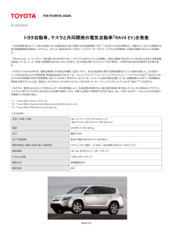
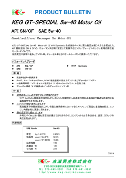
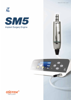
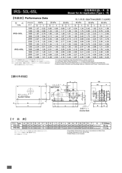
HM-40051-14 取 扱 説 明 書 ステッピングモーターユニット ARシリーズ モーター編 はじめに お使いになる前に 製品の取り扱いは、電気・機械工学の専門知識を持つ有資格者が行なってください。 お使いになる前に、 「安全上のご注意」をよくお読みのうえ、正しくお使いください。 この製品は、一般的な産業機器の機器組み込み用として設計・製造されています。 その他の用途には使用しないでください。この警告を無視した結果生じた損害の 補償については、当社は一切その責任を負いませんので、あらかじめご了承くだ さい。 お買い上げいただきありがとうございます。 この取扱説明書には、製品の取り扱いかたや安全上の注意事項を示しています。 yy取扱説明書をよくお読みになり、製品を安全にお使いください。 yyお読みになったあとは、いつでも見られるところに必ず保管してください。 その他の指令 zz RoHS指令 RoHS指令(2011/65/EU)の規制値を超える物質は含有していません。 安全上のご注意 ここに示した注意事項は、製品を安全に正しくお使いいただき、お客様や他の人々 への危害や損傷を未然に防止するためのものです。内容をよく理解してから製品 をお使いください。 取扱説明書の構成 ARシリーズに関する取扱説明書には、次のものがあります。 よくお読みになってからお使いください。 •• ARシリーズ 取扱説明書 モーター編(本書) モーターの機能や設置方法などについて説明しています。 •• ARシリーズ 取扱説明書 ドライバ編(ドライバに付属) ドライバの機能や設置方法などについて説明しています。 •• ARシリーズ ユーザーズマニュアル モーター、ドライバの機能、設置・接続方法、トラブルシューティングなどについ て説明しています。製品には添付していません。詳細は支店・営業所にお問合せい ただくか、当社の WEBサイトからダウンロードしてください。 http://www.orientalmotor.co.jp/ •• APPENDIX UL Standards for AR Series(製品に添付) UL規格の認証に必要な情報を記載しています。 法令・規格 CEマーキング ARシリーズ AC電源入力ドライバと組み合わせるモーターは、低電圧指令と EMC 指令にもとづいて CEマーキングを実施しています。 zz 低電圧指令 EN 60034-1 については、TÜV Rheinlandの認定を取得しています。 (ARM911MC-PFを除く。) yyIT配電系統では使用できません。 yy製品は、筐体内に設置し、人の手が触れられないようにしてください。 yy製品に人の手が触れられるときは、必ず保護接地をしてください。モーター、 ドライバの保護接地端子は、確実に接地してください。 yy漏電遮断器 (RCD)で感電保護を行なうときは、タイプ Bの漏電遮断器をドライ バの電源側に接続してください。 yy配線用遮断器 (MCCB)は、ENまたは IEC規格適合品を使用してください。 yyモーターケーブルや電源ケーブルなどの動力系ケーブルと、信号系のケーブル は、二重絶縁で分離してください。 yy駆動条件によっては、ドライバのヒートシンクが 90 °Cを超えることがありま す。次のことを守ってください。 ・ドライバに触れないでください。 ・可燃物のそばでドライバを使用しないでください。 ・必ず試運転を行ない、ドライバの温度を確認してください。 この警告事項に反した取り扱いをすると、死亡または重傷を負う場合がある内容 を示しています。 全般 yy爆発性雰囲気、引火性ガスの雰囲気、腐食性の雰囲気、水のかかる場所、可燃 物のそばでは使用しないでください。火災・感電・けがの原因になります。 yy設置、接続、運転・操作、点検・故障診断の作業は、適切な資格を有する人が行なっ てください。火災・感電・けが、装置破損の原因になります。 yy通電状態で移動、設置、接続、点検の作業をしないでください。電源を切って から作業してください。感電の原因になります。 yy昇降装置に使用するときは、可動部の位置保持対策を行なってください。電源 OFF時、モーターは保持力がなくなるため、可動部が落下して、けが・装置破損 の原因になります。 yy電磁ブレーキ付モーターのブレーキ機構は、可動部とモーターの位置保持用で す。制動・安全ブレーキとして使用しないでください。けが・装置破損の原因に なります。 設置 yyモーターはクラスⅠ機器に設置してください。感電の原因になります。 (ドライ バの電源が DC24 Vのときは必要ありません。) yy設置するときは、手がモーターに触れないようにするか、接地してください。 感電の原因になります。 接続 yy取扱説明書ドライバ編またはユーザーズマニュアルに記載されているモーター の接続方法にもとづき、確実に接続してください。火災・感電の原因になります。 yy接続ケーブルを無理に曲げたり、引っ張ったり、挟み込まないでください。火災・ 感電の原因になります。 修理・分解・改造 yyモーターを分解・改造しないでください。感電・けがの原因になります。内部の 点検や修理は、お買い上げになった支店または営業所に連絡してください。 この注意事項に反した取り扱いをすると、傷害を負うまたは物的損害が発生する 場合がある内容を示しています。 全般 EN 60034-1、EN 60034-5、EN 60664-1 yyモーターの仕様値を超えて使用しないでください。感電・けが・装置破損の原因 になります。 yy運転中、 および停止後しばらくの間は、モーターに触れないでください。モーター の表面が高温のため、やけどの原因になります。 •• 設置条件 運搬 •• 適用規格 yy機器組み込み yy過電圧カテゴリー:Ⅱ yy汚損度:3(両軸タイプ、PFギヤードタイプ、IP20 仕様モーターは 2) yy感電保護:クラスⅠ yyモーターの保護接地端子は、確実に接地してください。 yyモーター出力軸やモーターケーブルを持たないでください。けがの原因になり ます。 1 •• ノイズ対策 設置 yyモーターの回転部(出力軸)にカバーを設けてください。けがの原因になります。 yy通風を妨げる障害物をモーターの周囲に置かないでください。装置破損の原因 になります。 運転 yy運転中は回転部(出力軸)に触れないでください。けがの原因になります。 yy装置の故障や動作の異常が発生したときは、装置全体が安全な方向へはたらく よう非常停止装置、または非常停止回路を外部に設置してください。けがの原 因になります。 yyモーターは、正常な運転状態でも表面温度が 70 °Cを超えること があります。運転中のモーターに接近できるときは、図の警告ラ ベルをはっきり見える位置に貼ってください。やけどの原因にな ります。 警告ラベル yy電磁ブレーキ用の直流電源は、一次側と強化絶縁された電源を使用してくださ い。感電の原因になります。 ノイズ対策についてはユーザーズマニュアルをご覧ください。 •• ギヤードタイプの瞬時最大トルク ギヤードタイプは、必ず瞬時最大トルク以下の負荷で運転してください。 瞬時最大トルクを超えた負荷が加わると、ギヤが破損します。 •• ギヤードモーターのグリース ギヤードモーターからまれに、少量のグリースがにじみ出ることがあります。グ リース漏れによる周囲環境の汚染が問題になるときは、定期点検時にグリースの にじみを確認してください。または油受けなどの損害防止装置を取り付けてくだ さい。油漏れによって、お客様の装置や製品などに不具合を発生させる原因にな ります。 •• ギヤ出力軸の回転方向 モーター出力軸とギヤ出力軸の回転方向の関係は、ギヤの種類や減速比によって 異なります。 保守・点検 yy絶縁抵抗測定、絶縁耐圧試験を行なうときは、端子に触れないでください。感 電の原因になります。 廃棄 yyモーターを廃棄するときは、できるだけ分解し、産業廃棄物として処理してく ださい。 使用上のお願い 製品をお使いいただくうえでの制限やお願いについて説明しています。 •• モーターとドライバの接続には、付属またはオプションのケーブルを お使いください モーターとドライバは、必ず付属またはオプションのケーブルを使用して接続し てください。 次の場合は、オプションのケーブルを別途お買い求めください。 yy可動ケーブルを使用するとき yy3 mよりも長いケーブルを使用するとき yyケーブルが添付されていないユニット品を購入したとき •• 絶縁抵抗測定、絶縁耐圧試験は、モーターとドライバそれぞれで行なっ てください モーターとドライバを接続した状態で、絶縁抵抗測定、絶縁耐圧試験を行なうと、 製品が破損するおそれがあります。 •• ラジアル荷重・アキシアル荷重は許容値以下で使用してください 許容値を超えたラジアル荷重やアキシアル荷重が加わった状態で運転を続けると、 モーターの軸受け(ボールベアリング)が破損する原因になります。必ず許容値内 のラジアル荷重・アキシアル荷重で運転してください。詳細は 4 ページをご覧くだ さい。 •• モーターは表面温度 100 °C以下を目安に使用してください ドライバには過熱から保護する機能がありますが、モーター自体にはそのような 機能がありません。使用周囲温度、運転速度、運転デューティなどの運転条件によっ ては、モーターケースの表面温度が 100 °Cを超える場合があります。モーターの 軸受け(ボールベアリング)の寿命劣化を抑えるため、モーターケースの表面温度 は 100 °C以下を目安に使用してください。 ギヤードタイプは、ギヤ部のグリースや部材の劣化を防ぐため、ギヤ部のケース 温度は 70 °C以下で使用してください。 モーターを連続運転するときは、放熱板(材質:アルミニウム、250×250×6 mm) と同程度の放熱能力を持つ場所に設置してください。 減速比 モーター出力軸に 対する回転方向 3.6、7.2、10 同方向 20、30 逆方向 PLギヤ、PSギヤ、PNギヤ、 PFギヤ、FCギヤ 全減速比 同方向 ハーモニックギヤ 全減速比 逆方向 ギヤの種類 THギヤ •• ギヤードモーターでは押し当て運転を行なわないでください モーターやギヤ部が破損するおそれがあります。 準備 製品の確認 次のものがすべて揃っていることを確認してください。不足したり破損している 場合は、お買い求めの支店・営業所までご連絡ください。 yyモーター......................................................1 台 yy平行キー......................................................1 個※ 1 yyバリスタ......................................................1 個※ 2 yyモーター用ケーブル...................................1 本※ 3 yy電磁ブレーキ用ケーブル............................1 本※ 3 ※ 4 yy取扱説明書 モーター編 (本書)...................1 部 ※ 1 ギヤードタイプに付属。ただし、次のギヤードタイプには付属していません。 THギヤード:ARM24-T、ARM46-T、ARM66-T PLギヤード:ARM46-P PSギヤード:ARM24-PS PNギヤード:ARM24-N PFギヤード:全種類 ハーモニックギヤード:ARM24-H ※ 2 DC電源入力 パルス列入力タイプと組み合わせる電磁ブレーキ付モーター に付属。 ※ 3 ケーブルが添付されているユニット品のみ。 ※ 4 電磁ブレーキ付のみ。 各部の名称 zz 標準タイプ 電磁ブレーキ付(例:ARM66MC) •• 両軸タイプのモーター モーター出力軸の反対側の出力軸に、負荷トルク、ラジアル荷重、およびアキシ アル荷重を加えないでください。 モーター 保護接地端子 取付穴 (4か所) •• 停止時の保持トルク モーターの停止時は、ドライバのカレントダウン機能によって保持トルクが低下 します。モーターを選定するときは、カタログで停止時保持トルクを確認してく ださい。 •• 電磁ブレーキを制動・安全ブレーキとして使用しないでください 電磁ブレーキをモーターの制動停止に使用しないでください。電磁ブレーキのブ レーキハブが著しく磨耗して、制動力が低下します。電磁ブレーキは無励磁作動 型のため、停電時などに負荷を保持するのに役立ちますが、負荷を確実に保持す る機構ではありません。安全ブレーキとして使用しないでください。電磁ブレー キで負荷を保持するときは、モーターの停止後に行なってください。 2 電磁ブレーキ 出力軸 インロー モーターケーブル カプラカバー 電磁ブレーキケーブル カプラカバー zz PFギヤードタイプ(例:ARM69AC-PF5) PFギヤのインロー取付面、および出力フランジ面には、防錆剤が塗 布されています。取付精度に影響するため、防錆剤を拭き取ってか らお使いください。 保護接地端子 モーター ギヤヘッド 種類 取付穴 (8か所) 出力フランジ 標準 モーターケーブル 負荷取付用ねじ穴 (7か所) 位置決め用ピン穴 (1か所) カプラカバー THギヤード インロー取付面 PLギヤード PSギヤード PNギヤード ハーモニックギ ヤード※ 1 設置 設置場所 モーターは機器組み込み用に設計・製造されています。 風通しがよく、点検が容易な次のような場所に設置してください。 PFギヤード yy屋内に設置された筐体内(換気口を設けてください) yy使用周囲温度:−10 ~ +50 °C(凍結しないこと) ハーモニックギヤードタイプは 0 ~ +40 °C(凍結しないこと) yy使用周囲湿度:85%以下(結露しないこと) yy爆発性雰囲気、有害なガス(硫化ガスなど)、および液体のないところ yy直射日光が当たらないところ yy塵埃や鉄粉などの少ないところ yy水(雨や水滴)、油(油滴)、およびその他の液体がかからないところ yy塩分の少ないところ yy連続的な振動や過度の衝撃が加わらないところ yy電磁ノイズ (溶接機、動力機器など)が少ないところ yy放射性物質や磁場がなく、真空でないところ yy海抜 1,000 m以下 FCギヤード ハーモニックギ ヤード※ 2 取付角寸法 (mm) ボルトの 呼び 締付トルク (N·m) 有効ねじ 深さ(mm) 20 M2 0.25 2.5 28 M2.5 0.5 2.5 42 M3 1 4.5 60 M4 2 85 M6 3 − 28 M2.5 0.5 42、60 M4 2 8 90 M8 4 15 28 M3 1 6 42 M4 2 8 60 M5 2.5 10 15 90 M8 4 Ø64 M4 2.5 Ø90 M5 5 42 M4 2 60 M5 2.5 90 M8 4 設置 方法 A B 4 A A − C※ 3 − B − B ※ 1 ARM24、ARM46、ARM66タイプのみ。 ※ 2 ARM98タイプのみ。 ※ 3 ねじの本数は 8 本です。 負荷の取り付け 負荷をモーターに取り付けるときは、負荷の軸中心線とモーター出力軸を揃えて ください。カップリングやプーリーをモーター出力軸に取り付けるときは、出力 軸や軸受け(ボールベアリング)に損傷を与えないでください。 zz 電磁ブレーキ付モーターの場合 設置方向 モーターの設置方向に制限はありません。 設置方法 放熱性や振動防止を考慮し、できるだけ強固な金属面へ確実に取り付けてくださ い。 •• 設置方法 A •• 設置方法 C 電磁ブレーキ付モーター 電磁ブレーキ用直流電源 DC24 V±5%※1※2 インロー受け インロー受け 電磁ブレーキを解放して負荷を取り付けるときは、電磁ブレーキ用の直流電源が 必要です。電磁ブレーキ用ケーブルを使用して、DC24 V±5%の直流電源をモー ターに接続してください。ケーブルが添付されているユニット品をご購入の場合、 電磁ブレーキ用ケーブルは製品に付属しています。 白 スイッチ 黒 バリスタ※3 電磁ブレーキ用ケーブル 金属板 金属板 •• 設置方法 B インロー受け 金属板 • FCギヤードの場合 インロー受け ※ 1 モーターとドライバ間を 20 m以上延長するときは、DC24 V±4%の電源 を使用してください。 ※ 2 電源電流容量は、次のとおりです。 ARM24、ARM26:0.05 A以上 ARM46:0.08 A以上 ARM66、ARM69、ARM98:0.25 A以上 ※ 3 スイッチの接点保護やノイズを防止するため、バリスタをご用意ください。 DC電源入力 パルス列入力タイプには付属しています。 [推奨バリスタ:Z15D121(SEMITEC株式会社)] 金属板 3 zz PFギヤードタイプの場合 出力フランジ PFギヤードタイプに負荷を取り付けるときは、出力 フランジの負荷取付用ねじ穴(7 か所)を使用してく ださい。出力フランジには、位置決め用ピン穴(1 か所)も加工されています。位置決めピンを使用し て負荷を位置決めする際にご利用ください。 yyラジアル荷重やアキシアル荷重が許容値を超えると、繰り返し荷重 によってモーターの軸受け(ボールベアリング)や出力軸が疲労破 損にいたる原因になります。 yy両軸タイプのときは、モーター出力軸の反対側の出力軸に、負荷ト ルク、ラジアル荷重、およびアキシアル荷重を加えないでください。 yy位置決めピンは、必ず負荷側に固定してください。位置決めピンを 出力フランジに打ち付けると、衝撃や過大なモーメントによって、 軸受けが破損するおそれがあります。 yy負荷取付用ねじの締付トルクが大きいため、強度が弱い負荷やねじ を使用すると、破損するおそれがあります。負荷および取付ねじは、 次の条件を満たしてください。また、必ず規定の締付トルクで固定 してください。 負荷の材質:鉄 取付ねじ:強度区分 12.9 以上のボルト •• 負荷取付用ねじ穴 モーター品名 ねじの呼び 締付トルク (N·m) 有効ねじ深さ (mm) ARM69 M5 8.0 7 ARM911 M6 15.0 10 •• 位置決め用ピン穴 モーター品名 ARM69 ARM911 ピン穴径(mm) Ø5 6 Ø6 + 0.012 0 7 (H7) zz 標準タイプ モーター 品名 ハーモニックギヤードタイプ(ARM98を除く)は、フランジ面にある負荷取付用の ねじ穴を使用して、負荷を直接ギヤに取り付けることができます。 負荷 ねじ 0 5 10 15 20 12 15 − − − 3 ARM24 ARM26 25 34 52 − − 5 ARM46 35 44 58 85 − 15 ARM66 ARM69 90 100 130 180 270 30 ARM98 ARM911 260 290 340 390 480 60 許容ラジアル荷重(N) モーター出力軸先端からの距離(mm) 20 許容アキシアル 荷重(N) 0 5 10 15 ARM24 15 17 20 23 − 10 ARM46 10 14 20 30 − 15 ARM66 70 80 100 120 150 40 ARM98 220 250 300 350 400 100 モーター 品名 モーター品名 ねじの 呼び ねじの 本数 締付トルク (N·m) 有効ねじ深さ (mm) ARM24 M3 4 1.4 4 ARM46 M3 6 1.4 5 ARM66 M4 6 2.5 6 yy負荷をフランジ面に取り付ける場合、出力軸のキーみぞを併用して 負荷を固定することはできません。 yyモーターを取り付けている金属板やねじと、負荷が干渉しないよう に設計してください。 ARM46 ARM66 ARM98 4 許容アキシアル 荷重(N) zz PLギヤードタイプ 負荷取付用の ねじ穴 金属板 許容ラジアル荷重(N) モーター出力軸先端からの距離(mm) ARM14 ARM15 モーター 品名 zz フランジ面に取り付けるとき(ハーモニックギヤードタイプ) フランジ面 PSギヤードタイプと PNギヤードタイプは、ラジアル荷重またはアキ シアル荷重のどちらかが作用した場合に、寿命が 20,000 時間を満 たす値を許容値としています。 zz THギヤードタイプ ピン穴深さ(mm) + 0.012 0 (H7) 許容ラジアル荷重、許容アキシアル荷重、許容モーメン ト荷重 許容ラジアル荷重(N) 減速比 モーター出力軸先端からの距離(mm) 0 5 10 15 20 5 7.2 10 73 84 100 123 − 25 36 50 109 127 150 184 − 5 200 220 250 280 320 7.2 10 250 270 300 340 390 25 36 50 330 360 400 450 520 5 7.2 10 480 540 600 680 790 25 850 940 1050 1190 1380 許容アキシア ル荷重(N) 50 36 930 1030 1150 1310 1520 50 1050 1160 1300 1480 1710 100 300 zz PFギヤードタイプ zz PSギヤードタイプ モーター 品名 ARM24 ARM46 ARM66 ARM98 許容ラジアル荷重(N) 減速比 5 7.2 10 モーター出力軸先端からの距離(mm) 0 5 10 15 20 45 60 80 100 − 許容アキシア ル荷重(N) 40 ARM69 許容モーメント 荷重(N·m) 5 200 10 10 300 12.5 20 400 40 500 16 70 80 95 120 − 5 400 45 80 90 110 140 − 10 600 55 10 85 100 120 150 − 20 800 25 120 140 170 210 − 40 1200 36 130 160 190 240 − 50 150 170 210 260 − 5 170 200 230 270 320 7.2 200 220 260 310 370 10 220 250 290 350 410 25 300 340 400 470 560 36 340 380 450 530 630 50 380 430 500 600 700 5 380 420 470 540 630 7.2 430 470 530 610 710 10 480 530 590 680 790 25 650 720 810 920 1070 36 730 810 910 1040 1210 50 820 910 1020 1160 1350 ARM911 100 ARM24 58 •• PFギヤードタイプの許容アキシアル荷重と許容モーメント 荷重 アキシアル荷重とモーメント荷重は、次の計算式で算出してください。 200 例 1:出力フランジの中心から距離 Lの位置に外力 Fが加わる 場合 L:出力フランジ中心からの距離(m) F:外力(N) F L アキシアル荷重 Fs[N]= F + 負荷の荷重 モーメント荷重 M[N·m]= F × L 600 例 2:出力フランジの取付面から距離 Lの位置に外力 F1 と F2 が加わる 場合 許容ラジアル荷重(N) 減速比 ARM98 許容アキシアル 荷重(N) 5 モーター 品名 ARM66 減速比 7.2 zz PNギヤードタイプ ARM46 モーター 品名 モーター出力軸先端からの距離(mm) 0 5 10 15 20 5 7.2 10 45 60 80 100 − 5 80 95 120 160 − 7.2 90 110 130 180 − 10 100 120 150 200 − 5 240 260 280 300 330 7.2 270 290 310 340 370 10 300 320 350 380 410 25 410 440 470 520 560 36 360 410 480 570 640 50 360 410 480 570 700 5 370 390 410 430 460 7.2 410 440 460 490 520 10 460 490 520 550 580 25 630 660 700 740 790 36 710 750 790 840 900 50 790 840 890 940 1000 許容アキシア ル荷重(N) 40 100 L:出力フランジ取付面からの距離(m) F1、F2:外力(N) F1 アキシアル荷重 Fs[N]= F1 + 負荷の荷重 モーメント荷重 M[N·m]= F2 ×(L + 係数 a) モーター品名 係数 a ARM69 0.022 ARM911 0.035 F2 L zz FCギヤードタイプ 200 600 モーター 品名 許容ラジアル荷重(N) モーター出力軸先端からの距離(mm) 20 許容アキシアル 荷重(N) 0 5 10 15 ARM46 180 200 220 250 − 100 ARM66 270 290 310 330 350 200 zz ハーモニックギヤードタイプ モーター 品名 ARM24 許容ラジアル荷重(N) モーター出力軸先端からの距離(mm) 0 5 10 15 20 100 135 175 250 − 許容アキシアル 荷重(N) 140 ARM46 180 220 270 360 510 220 ARM66 320 370 440 550 720 450 ARM98 1090 1150 1230 1310 1410 1300 5 ハーモニックギヤードタイプの許容モーメント荷重 アームやテーブルをフランジ面に取り付けるときに、偏心荷重が加わる場合は、 次の計算式でモーメント荷重を算出してください。モーメント荷重は、表の許容 値を超えないでください。 L L:出力フランジ中心からの距離(m) F F:外力(N) モーメント荷重:M(N·m)= F × L モーター品名 許容モーメント荷重(N·m) ARM24 2.9 ARM46 5.6 ARM66 11.6 点検 モーターの運転後は、定期的に次の項目について点検することをおすすめします。 異常があるときは使用を中止し、お客様ご相談センターにお問い合わせください。 点検項目 yyモーターの取付ねじに緩みがないか。 yyモーターの軸受け (ボールベアリング)などから異常な音が発生してないか。 yyモーター出力軸と負荷軸に心ズレがないか。 yyモーターケーブルに傷、ストレスや、ドライバとの接続部に緩みがないか。 一般仕様 接続 保護等級 ドライバとの接続 周囲温度 接続方法は、取扱説明書ドライバ編またはユーザーズマニュアルをご覧ください。 ケーブル同士を接続したコネクタはカプラカバーで覆ってください。 使用環境 モーターコネクタピン配列 yyドライバ:AC電源入力 6 7 8 9 10 1 2 3 4 5 yyドライバ:DC電源入力 6 7 8 9 10 1 2 3 4 5 IP65(取付面とコネクタ部を除く) IP20(両軸タイプ、PFギヤードタイプ、およびモーター品名に Sが 付いているもの※) ピン No. 線色 1 白 2 紫 3 赤 4 青 5 緑 線径 AWG26(0.14 mm2) AWG22(0.3 mm2) 6 黒 7 茶 8 灰 9 橙 10 − − ピン No. 線色 線径 1 白 2 黒 3 紫 4 茶 5※ 緑 6 赤 7 灰 8 青 9 橙 10 − AWG26(0.14 mm2) 輸送環境 AWG22(0.3 mm2) 湿度 85%以下(結露しないこと) 高度 海抜 1,000 m以下 雰囲気 腐食性ガス、塵埃がないこと。 水、油がかからないこと。 周囲温度 −20 ~ +60 °C(凍結しないこと) 湿度 85%以下(結露しないこと) 高度 海抜 3,000 m以下 雰囲気 腐食性ガス、塵埃がないこと。 水、油がかからないこと。 周囲温度 −20 ~ +60 °C(凍結しないこと) 湿度 85%以下(結露しないこと) 高度 海抜 3,000 m以下 雰囲気 腐食性ガス、塵埃がないこと。 水、油がかからないこと。 ※※ モーター銘板やユーザーズマニュアルなどでご確認ください。 AWG26(0.14 mm2) AWG22(0.3 mm2) − ※※ ARM14、ARM15、ARM24、ARM26にはありません。 モーターの接地 モーターの保護接地端子を確実に接地してくださ い。(ドライバの電源が DC24 Vのときは必要あ りません。) ねじサイズ:M4 締付トルク:1.2 N·m 接地線は AWG18(0.75 mm2)以上のものを使用 してください。 接地するときは丸型端子を使用し、座金を入れた ボルトで固定してください。接地線や圧着端子は 付属していません。 保存環境 −10 ~ +50 °C(凍結しないこと) ハーモニックギヤードタイプは 0 ~ +40 °C (凍結しないこと) yyこの取扱説明書の一部または全部を無断で転載、複製することは、禁止されてい ます。 yy取扱説明書に記載されている情報、回路、機器、および装置の利用に関して産業 財産権上の問題が生じても、当社は一切の責任を負いません。 yy製品の性能、仕様および外観は改良のため予告なく変更することがありますので ご了承ください。 yy取扱説明書には正確な情報を記載するよう努めていますが、万一ご不審な点や誤 り、記載もれなどにお気づきの点がありましたら、最寄りのお客様ご相談センター までご連絡ください。 yy と は、日本その他の国におけるオリエンタルモー ター株式会社の登録商標または商標です。 © Copyright ORIENTAL MOTOR CO., LTD. 2011 PE お問い合わせ窓口(フリーコールです。携帯・PHSからもご利用いただけます。) 技術的なお問い合わせ・お見積・ご注文の 総合窓口 お客様ご相談センター 受付時間 平日/8:00 ∼ 20:00 , 土曜日/9:00 ∼ 17:30 東 京 TEL 0120-925-410 FAX 0120-925-601 名古屋 TEL 0120-925-420 FAX 0120-925-602 大 阪 TEL 0120-925-430 FAX 0120-925-603 故障かな?と思ったときの 技術相談・訪問・検査修理窓口 アフターサービスセンター 受付時間 平日/9:00 ∼ 18:30 TEL 0120-911-271 FAX 0120-984-815 WEBサイトでもお問い合わせやご注文を受け付けています。 http://www.orientalmotor.co.jp/ 6 HM-40051-14 O P E R AT I N G M A N U A L Thank you for purchasing an Oriental Motor product. This Operating Manual describes product handling procedures and safety precautions. yy Please read it thoroughly to ensure safe operation. yy Always keep the manual where it is readily available. Stepping Motor and Driver Package AR Series Motor Introduction CE Marking All motors combined with a driver of the AR Series AC power input type are affixed the CE Marking under the Low Voltage Directive and EMC Directive. Before use Only qualified personnel should work with the product. Use the product correctly after thoroughly reading the section “Safety precautions.” The product described in this manual has been designed and manufactured to be incorporated in general industrial equipment. Do not use for any other purpose. Oriental Motor Co., Ltd. is not responsible for any damage caused through failure to observe this warning. Operating Manuals for AR Series Operating manuals for the AR Series are listed below. Read the manuals carefully before using the product. •• AR Series OPERATING MANUAL Motor (this document) This manual explains the motor functions and how to install the motor, among others. •• AR Series OPERATING MANUAL Driver (Supplied with driver) This manual explains the driver functions and how to install the driver, among others. •• AR Series USER MANUAL zz Low Voltage Directive This product is certified by TÜV Rheinland under the EN 60034-1. yy This product is designed and manufactured to be incorporated in equipment. yy This product cannot be used with cables normally used for IT power distribution systems. yy Install the product within the enclosure in order to avoid contact with hands. yy When a product can be touched with hands, be sure to ground. When installing the motor and driver, securely connect their Protective Earth Terminals. yy To protect against electric shock using an earth leakage breaker (RCD), connect a type B earth leakage breaker to the primary side of the driver. yy When using a circuit breaker (MCCB), use a unit conforming to the EN or IEC standard. yy Isolate the motor cable, power-supply cable and other drive cables from the signal cables by means of double insulation. yy The temperature of the driver's heat sink may exceed 90 °C (194 °F) depending on the driving conditions. Accordingly, take heed of the following items: • Do not touch the driver. • Do not use the driver near flammable objects. • Always conduct a trial operation to check the driver temperature. This manual explains the function, installation and connection of the motor and driver as well as operating method. The USER MANUAL does not come with the product. For details, contact your nearest Oriental Motor sales office or download from Oriental Motor website download page. •• Applicable Standards Regulations and standards •• Installation conditions UL Standards and CSA Standards All motors combined with a driver of the AR Series AC power input type conform to the UL/CSA Standards. Applicable Standards UL 1004-1, UL 1004-2, UL 1004-6 CSA C22.2 No.100, CSA C22.2 No.77 Certification Body Standards File No. UL E64199 AR series motor (AC power input type) is recognized under UL 1004-1, -6 based on the condition shown herein. The following shows the stepping motor specifications (Maximum Voltage, Maximum current, Holding torque and Maximum speed). Characteristic Maximum Voltage [V] Maximum Current [A] Heat sink size *2 [mm] Holding Torque [N·m] ARM46C 0.49 115×115×5 0.3 ARM66C 0.74 ARM69C 340 yy To be incorporated in equipment yy Overvoltage category: II yy Pollution degree: 3 (2 for the double-shaft type and IP20 type) yy Protection against electric shock: Class I yy Be sure to ground the Protective Earth Terminal of the motor. Other Directive Applicable Standards Motor model *1 yy EN 60034-1 yy EN 60034-5 yy EN 60664-1 0.92 ARM98C 1.13 ARM911C 1.27 2 The products do not contain the substances exceeding the restriction values of RoHS Directive (2011/65/EU). Safety precautions The precautions described below are intended to prevent danger or injury to the user and other personnel through safe, correct use of the product. Fully understand the meaning of each item before using the product. Maximum Speed [r/min] Handling the product without observing the instructions that accompany a “Warning” symbol may result in serious injury or death. 1.2 250×250×6 zz RoHS Directive 4000 4 : Enter the motor type A (standard-single shaft-), B (standard-double shaft-), M (Electromagnetic Brake Type) in the box () within the model name. *1 All models may or may not be followed by a hyphen and any letters and/or any numbers. *2 The material of the heat sink is aluminum. General yy Do not use the product in explosive or corrosive environments, in the presence of flammable gases, locations subjected to splashing water, or near combustibles. Doing so may result in fire, electric shock or injury. yy Assign qualified personnel the task of installing, wiring, operating/controlling, inspecting and troubleshooting the product. Failure to do so may result in fire, electric shock, injury or damage to equipment. yy Do not transport, install the product, perform connections or inspections when the power is on. Always turn the power off before carrying out these operations. Failure to do so may result in electric shock. yy Provide a means to hold the moving parts in place for applications involving vertical travel. The motor loses holding torque when the power is shut off, allowing the moving parts to fall and possibly cause injury or damage to equipment. yy The brake mechanism of an electromagnetic brake motor is used to keep the moving part and motor in position. Do not use it as a deceleration/safety brake. Doing so may result in injury or damage to the equipment. 1 Installation yy To prevent the risk of electric shock, use the motor for class I equipment only. (Not required when the driver’s power supply specification is 24 VDC.) yy Install the motor so as to avoid contact with hands, or ground them to prevent the risk of electric shock. Connection yy Connect the motor securely according to the motor connection method explained in the USER MANUAL or OPERATING MANUAL (Driver). Failure to do so may result in fire or electric shock. yy Do not forcibly bend, pull or pinch the cables. Doing so may result in fire or electric shock. Repair, disassembly and modification yy Do not disassemble or modify the motor. This may cause electric shock or injury. Refer all such internal inspections and repairs to the branch or sales office from which you purchased the product. •• Use the motor in conditions where its surface temperature will not exceed 100 °C (212 °F). The driver has an overheat-protection function, but the motor has no such feature. The motor case’s surface temperature may exceed 100 °C (212 °F) under certain conditions (ambient temperature, operating speed, duty cycle, etc.). To prevent the motor bearings (ball bearings) from reaching its usable life quickly, use the motor in conditions where its surface temperature will not exceed 100 °C (212 °F). Use the geared type motor in a condition where the gear case temperature does not exceed 70 °C (158 °F), in order to prevent deterioration of grease and parts in the gear case. If the motor is to be operated continuously, install the motor in a location where heat dissipation capacity equivalent to a level achieved with a heat sink [made of aluminum, 250×250×6 mm (9.84×9.84×0.24 in.)] is ensured. •• Double shaft motor Do not apply load torque, radial load or axial load to the output shaft on the opposite side of the motor output shaft. •• Holding torque at standstill Handling the product without observing the instructions that accompany a “Caution” symbol may result in injury or property damage. General yy Do not use the motor beyond its specifications, or electric shock, injury or damage to equipment may result. yy Do not touch the motor during operation or immediately after stopping. The surface is hot and may cause a skin burn(s). •• Do not use the electromagnetic brake to reduce speed or as a safety brake. yy Do not hold the motor output shaft or motor cable. This may cause injury. Do not use the electromagnetic brake as a means to decelerate and stop the motor. The brake hub of the electromagnetic brake will wear significantly and the braking force will drop. The electromagnetic brake is of power-off activated type. This means that although it helps maintain the position of the load in the event of power outage, etc., this brake cannot securely hold the load in place. Accordingly, do not use the electromagnetic brake as a safety brake. To use the electromagnetic brake to hold the load in place, do so after the motor has stopped. Installation •• Preventing electrical noise yy Provide a cover over the rotating parts (output shaft) of the motor to prevent injury. yy To prevent the risk of damage to equipment, leave nothing around the motor that would obstruct ventilation. •• Peak torque of geared type motor Transportation Operation yy Do not touch the rotating parts (output shaft) of the motor during operation. This may cause injury. yy Provide an emergency stop device or emergency stop circuit external to the equipment so that the entire equipment will operate safely in the event of a system failure or malfunction. Failure to do so may result in injury. yy The motor’s surface temperature may exceed 70 °C (158 °F), even under normal operating conditions. If a motor is accessible during operation, post a warning label shown in the figure in a conspicuous position to prevent the risk of skin burn(s). Warning label yy For the power supply input to the electromagnetic brake, use a DC power supply with reinforced insulation on the primary side. Maintenance and inspection yy To prevent the risk of electric shock, do not touch the terminals while measuring the insulation resistance or conducting a voltage-resistance test. Disposal yy To dispose of the motor, disassemble it into parts and components as much as possible and dispose of individual parts/components as industrial waste. Precautions for use See USER MANUAL for measures with regard to noise. Always operate the geared type motor under a load not exceeding the peak torque. If the load exceeds the peak torque, the gear will be damaged. •• About grease of geared motor On rare occasions, a small amount of grease may ooze out from the geared motor. If there is concern over possible environmental damage resulting from the leakage of grease, check for grease stains during regular inspections. Alternatively, install an oil pan or other device to prevent leakage from causing further damage. Oil leakage may lead to problems in the customer’s equipment or products. •• Rotation direction of the gear output shaft The relationship between the rotation direction of the motor shaft and that of the gear output shaft changes as follows, depending on the gear type and gear ratio. Type of gear Gear ratio Rotation direction (relative to the motor rotation direction) 3.6, 7.2, 10 Same direction 20, 30 Opposite direction PL geared, PS geared PN geared All gear ratios Same direction Harmonic geared All gear ratios Opposite direction TH geared •• Do not perform push-motion operation with geared types. This section covers limitations and requirements the user should consider when using the product. Doing so may cause damage to the motor or gear part. •• Always use the cable (supplied or accessory) to connect the motor and driver. Preparation Be sure to use the cable (supplied or accessory) to connect the motor and driver. In the following condition, an appropriate accessory cable must be purchased separately. yy If a flexible cable is to be used. yy If a cable of 3 m (9.8 ft.) or longer is to be used. yy If a motor and driver package without a cable was purchased. •• Conduct the insulation resistance measurement or dielectric strength test separately on the motor and the driver Conducting the insulation resistance measurement or dielectric strength test with the motor and driver connected may result in damage to the product. •• Do not apply a radial load and axial load in excess of the specified permissible limit. Operating the motor under an excessive radial load and axial load may damage the motor bearings (ball bearings). Be sure to operate the motor within the specified permissible limit of radial load and axial load. See page 4 for details. 2 The motor holding torque is reduced by the current cutback function of the driver at motor standstill. When selecting a motor, check the holding torque at motor standstill in the specifications on the catalog. Checking the product Verify that the items listed below are included. Report any missing or damaged items to the branch or sales office from which you purchased the product. zz When purchasing a motor and driver package yy Motor............................................................................ 1 unit yy Driver............................................................................ 1 unit yy Parallel key.................................................................. 1 pc. (Supplied with geared types) *1 yy Connectors bag......................................................... 1 pc (refer to the table on the right for the packing items) yy Varistor......................................................................... 1 pc. (Supplied with electromagnetic brake motors combined with a driver of DC power input Pulse input type) yy Cable for motor......................................................... 1 pc. *2 yy Cable for electromagnetic brake........................ 1 pc. *2 (Supplied with electromagnetic brake type) Installation yy OPERATING MANUAL Motor................................. 1 copy (this document) yy OPERATING MANUAL Driver................................. 1 copy *1 The parallel key does not come with the following geared type products. TH geared: ARM24-T, ARM46-T, ARM66-T PL geared: ARM46-P PS geared: ARM24-PS PN geared: ARM24-N Harmonic geared: ARM24-H *2 This does not come with the "product without cables." •• Packing items in connectors bag (AC power input type) Packing items Built-in controller type Pulse input type CN1 connector 1 pc. (6 pins) 1 pc. (6 pins) CN3 connector 1 pc. (5 pins) 1 pc. (5 pins) CN5 connector 1 pc. (5 pins) 1 pc. (36 pins) CN8 connector 1 pc. (9 pins) − CN9 connector 1 pc. (7 pins) − Connector wiring lever (for CN3 connector) 1 pc. 1 pc. •• Packing items in connectors bag (DC power input type) Built-in controller type Pulse input type CN1 connector 1 pc. (5 pins) 1 pc. (3 pins) CN5 connector 1 pc. (5 pins) 1 pc. (36 pins) CN8 connector 1 pc. (9 pins) − CN9 connector 1 pc. (7 pins) − zz When purchasing a motor only yy Motor............................................................................ 1 unit yy Parallel key.................................................................. 1 pc. (Supplied with geared types) * yy Varistor......................................................................... 1 pc. (Supplied with electromagnetic brake motors combined with a driver of DC power input Pulse input type) yy OPERATING MANUAL Motor................................. 1 copy (this document) ** The parallel key does not come with the following geared type products. TH geared: ARM24-T, ARM46-T, ARM66-T PL geared: ARM46-P PS geared: ARM24-PS PN geared: ARM24-N Harmonic geared: ARM24-H Names and functions of parts Protective earth terminal Mounting holes (4 locations) Pilot yy Inside an enclosure that is installed indoors (provide vent holes) yy Operating ambient temperature −10 to +50 °C (+14 to +122 °F) (non-freezing) Harmonic geard type: 0 to +40 °C (+32 to +104 °F) (non-freezing) yy Operating ambient humidity 85% or less (non-condensing) yy Area that is free of explosive atmosphere or toxic gas (such as sulfuric gas) or liquid yy Area not exposed to direct sun yy Area free of excessive amount of dust, iron particles or the like yy Area not subject to splashing water (rain, water droplets), oil (oil droplets) or other liquids yy Area free of excessive salt yy Area not subject to continuous vibration or excessive shocks yy Area free of excessive electromagnetic noise (from welders, power machinery, etc.) yy Area free of radioactive materials, magnetic fields or vacuum yy 1,000 m (3,300 ft.) or lower above sea level The motor can be installed in any direction. Installation method To allow for heat dissipation and prevent vibration, install the motor on a metal surface of sufficient strength. Electromagnetic brake Motor cable Connector cover Electromagnetic brake cable Connector cover •• Installation method B •• Installation method A Through hole for pilot Through hole for pilot Metal plate Metal plate •• Standard type Bolt size Tightening torque [N·m (oz-in)] Effective depth of bolt [mm (in.)] 20 (0.79) M2 0.25 (35) 2.5 (0.098) 28 (1.10) M2.5 0.5 (71) 2.5 (0.098) 42 (1.65) M3 1 (142) 4.5 (0.177) 60 (2.36) M4 2 (280) 85 (3.35) M6 3 (420) Frame size [mm (in.)] Bolt size 28 (1.10) 42 (1.65) 60 (2.36) 90 (3.54) Frame size [mm (in.)] This figure shows the ARM66MC. Output shaft The motor is designed and manufactured for installation in equipment. Install it in a wellventilated location that provides easy access for inspection. The location must also satisfy the following conditions: Installation direction Packing items Motor zz Location for installation Installation method A − B Tightening torque [N·m (oz-in)] Effective depth of bolt [mm (in.)] Installation method M2.5 0.5 (71) 4 (0.157) M4 2 (280) 8 (0.315) M8 4 (560) 15 (0.591) •• TH geared type A •• PL geared, PS geared, PN geared, Harmonic geared type (ARM24, ARM46 and ARM66 type) Frame size [mm (in.)] Bolt size Tightening torque [N·m (oz-in)] 28 (1.10) M3 1 (142) 6 (0.24) 42 (1.65) M4 2 (280) 8 (0.315) 60 (2.36) M5 2.5 (350) 10 (0.394) 90 (3.54) M8 4 (560) 15 (0.591) Effective depth of bolt [mm (in.)] Installation method A 3 •• Harmonic geared type (ARM98 type) Frame size [mm (in.)] Bolt size Tightening torque [N·m (oz-in)] Effective depth of bolt [mm (in.)] Installation method 90 (3.54) M8 4 (560) − B The permissible radial load and permissible axial load of the PS geared type and PN geared type represent the value that the service life of the gear part satisfies 20,000 hours when either of the radial load or axial load is applied to the gear output shaft. zz Standard type Installing a load Permissible radial load [N (lb.)] When connecting a load to the motor, align the centers of the motor’s output shaft and load shaft. Be careful not to damage the output shaft or the bearings (ball bearings) when installing a coupling or pulley to the motor’s output shaft. Distance from the tip of motor’s output shaft [mm (in.)] Motor model 0 (0) 5 (0.2) 10 (0.39) 15 (0.59) 20 (0.79) 12 (2.7) 15 (3.3) − − − zz Electromagnetic brake motor To release the electromagnetic brake and install the load, a DC power supply is needed to power the electromagnetic brake. Use a cable for electromagnetic brake to connect a DC power supply of 24 VDC±5% to the motor. When purchasing a motor and driver package product, the cable for electromagnetic brake cable is supplied with the product. DC power supply for electromagnetic brake Electromagnetic brake motor ARM24M 25 (5.6) 34 (7.6) 52 (11.7) − 35 (7.8) 44 (9.9) 58 (13) 85 (19.1) ARM46M 2.2 (0.49) 4.6 (1.03) − 6.1 (1.37) 8.8 (1.98) ARM66 ARM66M 90 (20) ARM69 Cable for electromagnetic brake *1 If the distance between the motor and driver is extended to 20 m (65.6 ft.) or longer, use a power supply of 24 VDC±4%. *2 The power supply current capacities are as follows. ARM24, ARM26: 0.05 A or more ARM46: 0.08 A or more ARM66, ARM69, ARM98: 0.25 A or more *3 To protect the switch contacts and prevent generation of noise, it is recommended that a varistor be used. If the driver is of DC power supply Pulse input type, a varistor is supplied with the motor. [Recommended varistor: Z15D121 (SEMITEC Corporation)]. With a Harmonic geared type (excluding ARM98), a load can be installed directly to the gear using the load mounting holes provided on the flange surface. Load mounting holes Bolts 100 (22) 130 (29) 180 (40) 11.8 (2.6) 270 (60) 13.7 (3) 16.7 (3.7) ARM69M ARM98 260 (58) ARM98M ARM911 290 (65) 340 (76) 390 (87) 18 (4) 480 (108) 24 (5.4) 29 (6.5) zz TH geared type Permissible radial load [N (lb.)] Distance from the tip of motor’s output shaft [mm (in.)] Motor model 0 (0) zz Installing on the flange surface (Harmonic geared type) Frange 2.1 (0.47) − 2.7 (0.6) ARM46 Varistor *3 Load 0.9 (0.2) 1.5 (0.33) ARM24 ARM26 Black Switch 0.7 (0.15) ARM26M 24 VDC±5% *1 *2 White ARM14 ARM15 Permissible axial load [N (lb.)] 5 (0.2) 10 (0.39) 15 (0.59) 20 (0.79) Permissible axial load [N (lb.)] ARM24 15 (3.3) 17 (3.8) 20 (4.5) 23 (5.1) − 10 (2.2) ARM46 10 (2.2) 14 (3.1) 20 (4.5) 30 (6.7) − 15 (3.3) ARM66 70 (15.7) 80 (18) 100 (22) 120 (27) 150 (33) 40 (9) ARM98 220 (49) 250 (56) 300 (67) 350 (78) 400 (90) 100 (22) zz PL geared type Metal plate Permissible radial load [N (lb.)] Bolt size Number of bolts Tightening torque [N·m (oz-in)] Effective depth of bolt [mm (in.)] ARM24 M3 4 1.4 (198) 4 (0.157) ARM46 M3 6 1.4 (198) 5 (0.2) ARM66 M4 6 2.5 (350) 6 (0.24) Motor model Motor model ARM46 yy When installing a load on the flange surface, the load cannot be affixed using the key groove in the output shaft. yy Design an appropriate installation layout so that the load will not contact the metal plate or bolts used for installing the motor. Permissible radial load and permissible axial load yy If the radial load or axial load exceeds the specified allowable value, repeated load applications may cause the bearing or output shaft of the motor (gearhead) to undergo a fatigue failure. yy With a double shaft type, do not apply load torque, radial load or axial load to the output shaft on the opposite side of the motor output shaft. 4 ARM66 Gear ratio Distance from the tip of motor’s output shaft [mm (in.)] 0 (0) 5 (0.2) 10 (0.39) 15 (0.59) 20 (0.79) 5 7.2 10 73 (16.4) 84 (18.9) 100 (22) 123 (27) − 25 36 50 109 (24) 127 (28) 150 (33) 184 (41) − 5 200 (45) 220 (49) 250 (56) 280 (63) 320 (72) 7.2 10 250 (56) 270 (60) 300 (67) 340 (76) 390 (87) 25 36 50 330 (74) 360 (81) 400 (90) 450 (101) 520 (117) Permissible axial load [N (lb.)] 50 (11.2) 100 (22) zz PN geared type Permissible radial load [N (lb.)] Motor model ARM98 Gear ratio Distance from the tip of motor’s output shaft [mm (in.)] 0 (0) 5 (0.2) 10 (0.39) 15 (0.59) 20 (0.79) 5 7.2 10 480 (108) 540 (121) 600 (135) 680 (153) 790 (177) 25 850 (191) 940 (210) 1050 (230) 1190 (260) 1380 (310) 36 930 (200) 1030 (230) 1150 (250) 1310 (290) 1520 (340) 50 1050 (230) 1160 (260) 1300 (290) 1480 (330) 1710 (380) Permissible axial load [N (lb.)] Permissible radial load [N (lb.)] Motor model Gear ratio ARM24 300 (67) ARM46 zz PS geared type Permissible radial load [N (lb.)] Motor model ARM24 Gear ratio Distance from the tip of motor’s output shaft [mm (in.)] 0 (0) 5 (0.2) 10 (0.39) 15 (0.59) 5 7.2 10 45 (10.1) 60 (13.5) 80 (18) 100 (22) 5 70 (15.7) 80 (18) 95 (21) 120 (27) − 7.2 80 (18) 90 (20) 110 (24) 140 (31) − 10 85 (19.1) 100 (22) 120 (27) 150 (33) − 25 120 (27) 140 (31) 170 (38) 210 (47) − 36 130 (29) 160 (36) 190 (42) 240 (54) − 50 150 (33) 170 (38) 210 (47) 260 (58) − 5 170 (38) 200 (45) 230 (51) 270 (60) 320 (72) 7.2 200 (45) 220 (49) 260 (58) 310 (69) 370 (83) 10 220 (49) 250 (56) 290 (65) 350 (78) 410 (92) 25 300 (67) 340 (76) 400 (90) 470 (105) 560 (126) 36 340 (76) 380 (85) 450 (101) 530 (119) 630 (141) 50 380 (85) 430 (96) 500 (112) 600 (135) 700 (157) 5 380 (85) 420 (94) 470 (105) 540 (121) 630 (141) 7.2 430 (96) 470 (105) 530 (119) 610 (137) 710 (159) 10 480 (108) 530 (119) 590 (132) 680 (153) 790 (177) 25 650 (146) 720 (162) 810 (182) 920 (200) 1070 (240) 36 730 (164) 810 (182) 910 (200) 1040 (230) 1210 (270) 50 820 (184) 910 (200) 1020 (220) 1160 (260) 1350 (300) ARM46 ARM66 ARM98 20 (0.79) − Permissible axial load [N (lb.)] Distance from the tip of motor’s output shaft [mm (in.)] 0 (0) 5 (0.2) 10 (0.39) 15 (0.59) 20 (0.79) 5 7.2 10 45 (10.1) 60 (13.5) 80 (18) 100 (22) − 5 80 (18) 95 (21) 120 (27) 160 (36) − 7.2 90 (20) 110 (24) 130 (29) 180 (40) − 10 100 (22) 120 (27) 150 (33) 200 (45) − 5 240 (54) 260 (58) 280 (63) 300 (67) 330 (74) 7.2 270 (60) 290 (65) 310 (69) 340 (76) 370 (83) 10 300 (67) 320 (72) 350 (78) 380 (85) 410 (92) 25 410 (92) 440 (99) 470 (105) 520 (117) 560 (126) 36 360 (81) 410 (92) 480 (108) 570 (128) 640 (144) 50 360 (81) 410 (92) 480 (108) 570 (128) 700 (157) 5 370 (83) 390 (87) 410 (92) 430 (96) 460 (103) 7.2 410 (92) 440 (99) 460 (103) 490 (110) 520 (117) 10 460 (103) 490 (110) 520 (117) 550 (123) 580 (130) 25 630 (141) 660 (148) 700 (157) 740 (166) 790 (177) 36 710 (159) 750 (168) 790 (177) 840 (189) 900 (200) 50 790 (177) 840 (189) 890 (200) 940 (210) 1000 (220) ARM66 40 (9) 100 (22) ARM98 Permissible axial load [N (lb.)] 40 (9) 100 (22) 200 (45) 600 (135) zz Harmonic geared type 200 (45) Permissible radial load [N (lb.)] Motor model 600 (135) Distance from the tip of motor’s output shaft [mm (in.)] Permissible axial load [N (lb.)] 0 (0) 5 (0.2) 10 (0.39) 15 (0.59) 20 (0.79) ARM24 100 (22) 135 (30) 175 (39) 250 (56) − 140 (31) ARM46 180 (40) 220 (49) 270 (60) 360 (81) 510 (114) 220 (49) ARM66 320 (72) 370 (83) 440 (99) 550 (123) 720 (162) 450 (101) ARM98 1090 (240) 1150 (250) 1230 (270) 1310 (290) 1410 (310) 1300 (290) Permissible moment load of the Harmonic geared type When installing an arm or table on the flange surface, calculate the moment load using the formula below if the flange surface receives any eccentric load. The moment load should not exceed the permissible value specified in the table. L: Distance from the center of the output flange [m (in.)] L F F: External force [N (oz)] Moment load: M [N·m (oz-in)] = F × L Motor model Permissible moment load [N·m (oz-in)] ARM24 2.9 (410) ARM46 5.6 (790) ARM66 11.6 (1640) 5 Connection General specifications Connecting to the driver Refer to OPERATING MANUAL (Driver) or USER MANUAL for the connection method. After the cables have been interconnected, cover each connector with the connector cover. Degree of protection Ambient temperature Motor connector pin assignment yy Driver: AC power supply input 6 7 8 9 10 1 2 3 4 5 yy Driver: DC power supply input 6 7 8 9 10 1 2 3 4 5 IP65 (Excluding the installation surface and connectors) IP20 (Double shaft type, models including “S” in the motor model *) Pin No. Lead color 1 White 2 Purple 3 Red 4 Blue 5 Green 6 Black Lead size 2 AWG26 (0.14 mm ) AWG22 (0.3 mm2) AWG26 (0.14 mm2) 7 Brown 8 Gray 9 Orange 10 − − Pin No. Lead color Lead size 1 White 2 Black 3 Purple 4 Brown 5∗ Green 6 Red 7 Gray 8 Blue 9 Orange 10 − Operation environment Storage environment AWG22 (0.3 mm2) Shipping environment 2 AWG26 (0.14 mm ) −10 to +50 °C (+14 to +122 °F) (non-freezing) Harmonic geard type: 0 to +40 °C (+32 to +104 °F) (non-freezing) Humidity 85% or less (non-condensing) Altitude Up to 1,000 m (3,300 ft.) above sea level Surrounding atmosphere No corrosive gas, dust, water or oil Ambient temperature −20 to +60 °C (−4 to +140 °F) (non-freezing) Humidity 85% or less (non-condensing) Altitude Up to 3,000 m (10,000 ft.) above sea level Surrounding atmosphere No corrosive gas, dust, water or oil Ambient temperature −20 to +60 °C (−4 to +140 °F) (non-freezing) Humidity 85% or less (non-condensing) Altitude Up to 3,000 m (10,000 ft.) above sea level Surrounding atmosphere No corrosive gas, dust, water or oil ** Check the model number of the motor against the number shown on the nameplate or USER MANUAL. AWG22 (0.3 mm2) − ** No wiring for ARM14, ARM15, ARM24 and ARM26. Grounding the motor Be sure to ground the Protective Earth Terminal of the motor. (Not required when the driver’s power supply specification is 24 VDC.) Screw size: M4 Tightening torque: 1.2 N·m (170 oz-in) Use a grounding wire larger than AWG18 (0.75 mm2). To ground the motor, use a round terminal and affix it with a bolt over an inner clip washer. The motor does not come with a Protective Earth cable or crimp terminal. PE Inspection It is recommended that periodic inspections be conducted for the items listed below after each operation of the motor. If an abnormal condition is noted, discontinue any use and contact your nearest office. During inspection yy Are any of the motor mounting screws loose? yy Check for any unusual noises in the motor’s bearings (ball bearings) or other moving parts. yy Are the motor’s output shaft and load shaft out of alignment? yy Are there any scratches, signs of stress or loose driver connections in the motor cable? yy Unauthorized reproduction or copying of all or part of this manual is prohibited. yy Oriental Motor shall not be liable whatsoever for any problems relating to industrial property rights arising from use of any information, circuit, equipment or device provided or referenced in this manual. yy Characteristics, specifications and dimensions are subject to change without notice. yy While we make every effort to offer accurate information in the manual, we welcome your input. Should you find unclear descriptions, errors or omissions, please contact the nearest office. and are registered trademark or trademark of Oriental yy Motor Co., Ltd., in Japan and other countries. Modbus is a registered trademark of the Schneider Automation Inc. © Copyright ORIENTAL MOTOR CO., LTD. 2011 • Please contact your nearest Oriental Motor office for further information. Technical Support Tel:(800)468-3982 8:30 A.M. to 5:00 P.M., P.S.T. (M-F) 7:30 A.M. to 5:00 P.M., C.S.T. (M-F) www.orientalmotor.com Tel:+55-11-3266-6018 www.orientalmotor.com.br Schiessstraße 74, 40549 Düsseldorf, Germany Technical Support Tel:00 800/22 55 66 22 www.orientalmotor.de Tel:01256-347090 www.oriental-motor.co.uk Tel:01 47 86 97 50 www.orientalmotor.fr Tel:02-93906346 www.orientalmotor.it 4-8-1Higashiueno,Taito-ku,Tokyo 110-8536 Japan Tel:03-6744-0361 www.orientalmotor.co.jp 6 Singapore Tel:1800-8420280 www.orientalmotor.com.sg Tel:1800-806161 www.orientalmotor.com.my Tel:1800-888-881 www.orientalmotor.co.th Tel:+91-80-41125586 www.orientalmotor.co.in Tel:0800-060708 www.orientalmotor.com.tw Tel:400-820-6516 www.orientalmotor.com.cn Korea Tel:080-777-2042 www.inaom.co.kr Hong Kong Branch Tel:+852-2427-9800
© Copyright 2026 Paperzz