INDEX / 目次
GENERAL PRODUCTS
CONTENTS
INDEX
Scope of Sumida products, general stipulations for coil use
Applications
3
4-9
Power Inductors
High-reliability metal Inductor
Recommended Automotive Application Type (High-temperature applicable)
Low Leakage Flux Type Inductor
Recommended Automotive Application Type (High-temperature applicable)
DC/DC converter inductors & output filter chokes for LED lighting
Chip Inductor
パワーインダクタ
高信頼性メタルインダクタ
車載向け高温対応インダクタ
低漏洩磁束タイプインダクタ
車載向け高温対応インダクタ
LED駆動用電源インダクタ
チップインダクタ
DC-DC Converter Transformer
General information
Transformers for UP-Down or Up Converter
High-temp Coil for SEPIC Converter
Step Up DC-DC Converter Transformers for Strobe
Gate Driver Transformers
Current sensor for Switching Power Supply and other circuit
SMD type Transformer for Automotive applications
PIN type Transformer for Automotive applications
PIN Type PFC Choke Coils
SMD type & Multiple Output Transformers
PIN type & Multiple Output Transformers
Leakage transformers for power supply
DC-DC コンバータ
概要
昇降圧コンバータトランス・昇圧コンバータトランス
車載SEPIC向け高温対応コイル
ストロボ回路用昇圧 DC/DC コンバータトランス
ゲートドライブトランス
カレントセンサー
車載向け面実装タイプトランス
Reactor
リアクタ
INVERTER
Notes on FL inverter transformer use
Application
High Reliability Inverter Transformers
Inverter Transformers
Inverter Units
Custom Specifications of inverter unit & Sample order form
インバータ
FLインバータトランス使用上の注意事項
用途
高信頼性インバータトランス
インバータトランス
インバータユニット
インバータユニットのカスタム仕様について & サンプルオーダーフォーム
EMC
Measurement condition, Product list
Characteristic List of Common Mode Choke coils for DC Lines
Common Mode Choke Coils for DC Lines (correspond 125˚C)
Common Mode Choke Coils for DC Lines
Common Mode Choke Coils for Communication
Signal and DC Common Mode Choke Coils
Normal Mode Choke Coils
AC Common Mode Choke Coils
EMC
測定条件、製品リスト
コモンモード DCフィルター特性一覧
DCライン向けコモンモードチョークコイル (125˚C対応)
DCライン向けコモンモードチョークコイル
有線通信用コモンモードチョークコイル
信号系コモンモードチョークコイル
ノーマルモードチョークコイル
AC コモンモードチョークコイル
Wireless Power Transfer Coil
Sensor Coils for Metal
ワイヤレス給電コイル
金属センサコイル
Antenna
Transponder : RFID (TX)
Transponder : RFID (RX)
TPMS : RFID
アンテナ
RFID トランスポンダーコイル(送信)
RFID トランスポンダーコイル(受信)
タイヤ空気圧モニタリングシステム用 RFID
IC TAG
IC タグ
For xDSL Line Transformers & Splitter Coils
xDSL Line Transformers
xDSL Line Transformer & Pots Splitter coil
xDSL Pots Splitter Coils
xDSL トランス / xDSL スプリッタコイル
xDSL トランス
xDSL トランス / xDSL スプリッタコイル
xDSL スプリッタコイル
123 - 128
129
130 - 132
xDSL Common Mode Choke Coil
Modem Transformers (MT series)
Modem Transformers (DAA)
PLC(Home Plug) Line Isolation Transformers
LAN PULSE Transformer
10/100 Base Pulse Transformers
Radio Control Clock Antennas
High Inductance Variable Coils
IFT Coils
RF Coils
VCO Coils
AM Antenna Loading Coils
Video Filters
Audio Filters
Helical Filter
Balun
xDSL コモンモードチョークコイル
モデム トランス(MTシリーズ)
モデム トランス(DAA)
ホームプラグライン絶縁トランス
LAN パルストランス
10/100ベース パルストランス
電波時計用アンテナ
可変コイル
IFT コイル
RF コイル
VCO コイル
AM アンテナローティングコイル
ビデオ フィルタ
オーディオ フィルタ
ヘリカルフィルタ
バルン
133
134 - 135
136
137 - 139
140
141 - 144
145 - 146
147
148
149
150
151
152
153
153
154
Dimensions for embossed tape and reel packing with packed QTY
キャリアテープ寸法・梱包数量
10
11- 14
15
16 - 18
19 - 20
21
車載向けPINタイプトランス
力率改善用チョークコイル
面実装多出力トランス
ピンタイプ多出力トランス
共振電源用トランス
Specifications in this catalog are subject to change without notice.
It is requested to confirm the specifications when ordering.
Any dimensions without tolerance is typical value.
Sumida declares that any ozone depleting substance is not used in the all coil manufacturing process.
We recommend to use resist to protect from solder bridge.
2
PAGE
目 次
スミダ製品の適用範囲、
コイル使用上の共通注意事項
アプリケーション
22 - 23
24 - 29
30
31 - 32
33
34 - 35
36 - 37
38
39
40 - 49
50 - 65
66
67
68 -69
70
71 - 74
75 - 78
79 - 80
81
82
83
84 - 86
87 - 89
90 - 91
92 - 98
99 - 101
102 - 111
112
113
114 - 118
119 - 120
121
122
155
本カタログは、記載内容を予告なく変更する事がありますのでご了承下さい。
なお、御注文に際しては、仕様・納入仕様書等の取り交わしをお願いします。
寸法図に公差のないものは参考値です。
当社製品の加工、組立等の全工程において一切のオゾン層破壊物質は使用しておりません。
はんだブリッジ対策の為、
レジスト等を用いる事を推奨します。
Scope of Sumida products, general stipulations for coil use / スミダ製品の適用範囲、コイル使用上の共通注意事項
Scope of Sumida products
1. Sumida components are manufactured and promoted for use in general electronics devices such as audio-video
equipment,home electric appliance,office automation equipment,in-car equipment,communication equipment,
measurement hardware,machine accessory and medical equipment.
2. In case of using the product for the purpose other than general electronics devices, please do not fail to consult
with our business headquarters, branch or business office.
When the suggested recommendations are not heeded, Sumida Group shall not be held liable for any dysfunction
in or damage to the equipment with which the product is used.
3. In the event a problem occurs which may affect industrial property and any other rights of Sumida Group (or a third
party) during the use of the product and information described in this catalog, Sumida Group shall not be held liable
for any such problem, nor grant any license to the offending party.
General stipulations for coil use
1. The specification is subject to change without prior notice as it deems necessary to reflect improvements or
changes.
2. Products should not be kept in unsuitable storage conditions, such as areas susceptible to high temperatures, high
humidity, dust or corrosion.
3. Don't use products in a place where dew condenses. Since dew condensation may be caused by temperature
change, please pay special attention when using products in a sealed condition.
4. Always handle products with care.
5. Don't touch electrodes directly with bare hands as oil secretions may inhibit soldering.
Always ensure optimum conditions for soldering.
6. Don't bend the terminals or subject them to excessive stress.
7. Please ensure that all terminals and case lugs are completely fixed with solder onto PCB.
8. Ensure the tuning slug or cap is not fixed by solder flux during the production process.
9. Refrain from rinsing coils. If necessary, please consult with our company.
10. Avoid placing coils near the edge of the PCB.
11. Our SMD coils are designed for automatic mounting. Please be careful if soldering by hand.
12. Don't touch any exposed winding part and avoid coming into contact with the guide of electrode in automatic
mounting.
13. Our specification limits the quality of the component as a single unit. Please ensure the component is thoroughly
evaluated in your application circuit.
14. When using our high voltage inverter transformers, place 2mm away from the electric conductor.
15. Products under development :
• A product with "PROVISIONAL" mark is under development at the moment.
• The specification is subject to change without prior notice as it deems necessary to reflect improvements
or changes.
• Please contact us for our mass production schedule.
Response to RoHS directive
Sumida products are RoHS compliance.
スミダ製品の適用範囲
1. 弊社製品は、AV機器、家電製品、OA機器、車載機器、通信機器、計測機器、工作機器及び医療機器などの一般電子機器に使用されることを前提に製造、
販売されております。
2. 万が一弊社製品を一般電子機器以外の用途に使用される場合は、必ず弊社営業部門にお問い合わせ下さい。また、使用条件を満たさない場合や超えた場
合による搭載機器に何らかの事故、損害が発生した場合でも弊社は一切その責を負いませんので、予めご了承下さい。
3. 弊社カタログに記載されている製品、もしくは情報使用に際して弊社または第三者の産業財産権(工業所有権)ほか、権利に係わる問題が発生した場合、
弊社はその責を負うものではありません。また、実施権の許諾を行うものではありません。
コイル使用上の共通注意事項
1.
2.
3.
4.
5.
6.
7.
8.
9.
10.
11.
12.
13.
14.
15.
製品の改善等により記載内容を予告なく変更することがありますのでご了承下さい。
製品は高温、多湿、麈埃、腐食性ガスの無い環境で保管して下さい。
結露する環境での使用は避けてください。密閉状態の環境で使用する場合は温度変化により結露をする恐れがありますので注意して下さい。
製品の落下や乱雑な取り扱い、バラ積みは、破損の恐れがありますので注意して下さい。
手脂によりはんだ付け性が劣化しますので、端子に直接手を触れないで下さい。
端子への過度なストレスは断線の原因になりますので、端子は折り曲げないで下さい。
端子及びケースのラグ部は、全てプリント基板にはんだ付けをして下さい。
調整コアがはんだ付けフラックスにより固定されないよう、生産工程に注意して下さい。
コイルの洗浄はしないで下さい。もし、洗浄が必要な場合は連絡して下さい。
プリント基板設計の際は、コイルは端面部への配置を避けて下さい。
面実装コイルは自動実装を基準に設計されていますので、手はんだの場合は取り扱いに注意して下さい。
コイルを自動実装される場合は、巻線露出部分への接触を避けて下さい。また、端子をガイドとして使用しないで下さい。
弊社納入仕様書は、部品単体での品質を規定するものです。ご使用に際しては、御社製品に実装された状態で必ず評価、ご確認をお願い致します。
高電圧を発生させるインバ−タトランスでは、導体はトランスから2mm以上離す設計をして下さい。
開発中製品について
・ PROVISIONAL マークのついている製品は現在開発中です。
・ 製品の改善等により記載内容を予告なく変更することがありますのでご了承下さい。
・ 量産時期についてはお問合せ下さい。
RoHS指令対応
スミダ製品は、RoHSに対応しています。
3
Applications
Applications
It shows you that which Sumida products are used in each applications block diagram.
アプリケーション内部をブロックダイヤグラムで示し、
どの部分にスミダ製品が使用されるかを記しました。
Note PC
ノートパソコン
LAN transformer
LCD
display
AC common mode choke
LF1290
LAN
PCM/CIA
AC adaptor
USB
CLP8D23
RF LAN
Normal mode choke
RCH series
LED
Internal modem
Modem transformer
Switching transformer
EE, EI, ERH, EEH series
CDRH series
CBM5D33B
CLK GENERATOR
Power circuit
Power inductor
CDMC series
CPU
CHIP-SET
HDD
DC common mode choke
CDEP series
Power inductor
CDH series
CD-ROM CD-RW
DVD-ROM driver
CDRH series
CSLF4D17
CDBH series
CBM4D19
CPFC6D36
Power inductor
CDH series
CDEIR series
Display Monitor
ディスプレイモニター
USB
OSD
MEMORY
DC Common mode choke
CSLF4D17
Video
AMP
Video
output
Synchronous
Division
circuit
Vertical
deflection
Horizontal
drive
Vertical
deflection
output
Swithing power supply
LCD display
Dynamic Focus
Power circuit
AC common mode choke AC common mode choke
UUH10LFB
PFC2225B
Normal mode choke
RCH series
DC common mode choke
CSLF4D25
CEP series
SMD power inductor
CDR series
Switching transformer Normal mode choke
PQ3221
EE, EI, ERH, EEH series
4
Backlight module
for LED
Audio
AMP
CDRH series
CDMC series
LPF
CDEP series
Applications
DVC ( Digital video camera )
デジタルビデオカメラ
Strobe area
CCD camera area
LCD
Transformer for step up
CMS series
Power circuit
CPU
Power inductor
CDRH, CDH, CDMPIH series
DC/DC converter transformers
CLS series
Shake
reduction
White LED
backlight
Power inductor
Power inductor
CDRH, CDH, CDMPIH
series
CDRH3D** series
LCD driver
BATT
DC/DC converter transformer
DC/DC converter
transformers
CLS series
CLQ series
AC adaptor
SEPIC convertor
CLS series
AC common mode choke
LF series
Common mode choke
RCH series
DSC ( Digital still camera )
デジタルスチルカメラ
Strobe area
CCD camera area
DC/DC converter transformer
LCD
Transformer for step up
CMS series
Power circuit
Power inductor
CDRH, CDH series
CPU
CLQ series
CLS series
Shake
reduction
White LED
backlight
Power inductor
Power inductor
CDRH, CDH series
CDRH3D** series
LCD driver
DC/DC converter
transformer
BATT
DC/DC converter transformer
CLQ series
SEPIC convertor
CLQ series
SEPIC convertor
CLS series
CLS series
5
Applications
Printer
プリンタ
USB I/F
Paper feed
motor
DC common mode choke
Printing head
CRR32
Gate array
DC Common mode choke
Head cleaning
timer
CPFC6D36
CPFC11D60
CPU
Power circuit
Power inductor
CDEP series
CDBH series
DC cable
Power inductor
CDRH series
Swithing power supply
AC common mode choke
LF series
Switching transformer
EE, EI, ERH, EEH series
Normal mode choke
RCH series
PLC ( HD-PLC, UPA, Home plug )
Coupler
Transformer
I/F
LAN transformer
Coupler transformer
PLC chip
CLP8D23
BM10D7
Common
mode choke
Normal
mode choke
AC common
mode choke
Switching
transformer
EEH series
Commutation
BM1007
CDRH5D** series
LF2020
LF2628
6
EEH116
EEH157
Applications
Hard disk drive
ハードディスクドライブ
DC/DC converter
Pre AMP
Read / write
Channel
Head
CDH series
Media
DC common
mode choke
CDRH series
Interface
VCM
SMD power inductor
Motor drive
Analogue ASIC
Interface
CPFC11D60
System servo controller
DVD Recorder
L1
R2
DVDレコーダー
R1
V2
V1
S-OUT
L2
Component video out
DC common mode choke
CSLF4D17
CSLF4D25
MPEG2
DVD sound
CD-ROM
CD
Optical pickup
Power inductor
CDRH series
VCC
LAN
Internal modem
LAN transformer
Modem transformer
CLP0612
CLP8D23
Power circuit
DC/DC converter transformer
CBM5D33B
LC, CLQ series
Swithing power supply
AC common mode choke
LF2628
Switching transformer
EE, EI, ERH, EEH series
Normal mode choke
PQ, EE, E series
7
Applications
Flat TV
LC Filter
フラットテレビ
Power inductor
CDRH65
Digital AMP
Tuner
Audio
SMD power inductor
MPEG
decoder
CSLF4D17
CSLF4D25
CRR32
LAN
Swithing power supply
Internal
modem
SMD power inductor
CDMC series
AC common mode
LF, PFC series
Modem
transformer
CBM5D33B
PFC
PQ, EE, E series
Switching transformer
EE, EI series
8
DC/DC converter
SMD power inductor
CDRH series
CDEP series
LCD panel
MCU
HDMI
DATA processing
CLP8D23
CDRH series
driver
controller
Analogue RGB
LAN
transformer
Headphone
DC/DC converter
DC common mode choke
Video
Terminal D
CDEPI106
Backlight module
for LED
CDRH series
CDMC series
CDRH series
CDEP series
CDRR series
CEP series
CDMC series
Applications
Game machine
USB
ゲームマシン
Audio output-L Audio output-R Video output
Terminal S
RF output
Line out connector
DC common mode choke
CSLF4D25
CSLF4D17
LAN
CPU
LAN transformer
SMD power inductor
CD-ROM
CD, DVD-ROM
Optical pickup
CLP8D23
CDEP series
MEMORY
Internal modem
Modem transformer
CBM5D33B
CDRH series
CDMC series
Swithing power supply
Power circuit
SMD power inductor
AC common mode choke
LF series
AC common mode choke
PFC series
CDRH series
Switching transformer
EE, EI, ERH, EEH series
CDMC series
Normal mode choke
RCH series
9
Power Inductors < High-reliability Metal Type >
Power Inductors < High-reliability Metal Type >
Power Inductors
SMD Shielded Type
CDMC**D**
(高信頼性メタルタイプ)
High-reliability Metal Type
OUTLINE
/ 概要
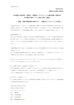
Large current SMD power inductor with metal composite material.
Compliance with AEC-Q200 reliability test condition & TS16949 quality management system.
Operational temperature range : -40°C~+150°C (excluding self-heating)
Application : Boost converter for idling stop system and large current filter.
金属磁性粉末材料を用いた大電流タイプのSMDパワーインダクタ。
AEC-Q200信頼性試験準拠、TS16949品質マネージメント対応。
使用温度範囲:-40∼+150℃(コイル自己発熱含まず)
アイドリングストップ向け昇圧電源、各種大電流フィルターに最適。
CDMC80D50/AA
DIMENSIONS (mm)
LAND PATTERNS (mm)
CONNECTION
外形寸法図
推奨ランド寸法
端子接続
NEW
4.5
2.0
12.4
3.8
4.0
2.0
3.0
Max.5.4
Max.8.4
Max.8.9
BOTTOM VIEW
裏面図
PROVISIONAL
Inductance Range / インダクタンス範囲
CDMC80D50/AA
1.3µH - 47µH
Measuring Freq.(L)100kHz / インダクタンス測定周波数100kHz
NOTE / 特記事項
Please note that when using the product for automotive while applying current with audio-frequency (AF) signals may result in audible noises due to magnetostriction.
Also, in order to avoid an audible noise problem, operating with Non-AF signals would be recommended.The noise may amplify depending on the coil mount area on the PCB.
車載向け製品に可聴周波数を含んだ電流を流すと磁歪現象によるうなりが生じ、
うなり音が聞こえる場合がありますので、
うなり音が問題となるような用途で御使用の場合は、
可聴周波数及び可聴周波数成分を含んだ電流を流さないようにして下さい。また、御使用基板での搭載場所によっては、
うなり音を増幅させる可能性もありますので御注意下さい。
About CDMC80D50/AA
This specification might be changed without notice due to under developing and improving. Please contact us for our mass production schedule.Thank you for your understanding.
本仕様は開発中につき、製品の改善等により記載内容を予告なく変更することがありますので、ご了承下さい。量産時期についてはお問合せ下さい。
10
Power Inductors < For Automotive Application >
SMD Shielded Type
(車載向け高温対応インダクタ)
Recommended Automotive Application Type Withstand up to 180˚C (including self-heating)
OUTLINE
/ 概要
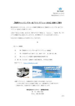
Operational Ambient Temperature : -40°C~150°C(withstand up to 180°C including self-heating)
Automotive reliability comply with AEC-Q200 standard.
It is the power inductor for automotive DC/DC converter application with reinforced shock & vibration-proof construction.
使用温度範囲:-40∼150℃(コイル自己発熱を含み上限180℃)
車載信頼性基準 AEC-Q200準拠
耐振動性・耐衝撃性が向上され、車載ニーズのDC/DCコンバータ向けパワーインダクタに最適です。
CDRH60D28/AA
DIMENSIONS (mm)
LAND PATTERNS (mm)
CONNECTION
外形寸法図
推奨ランド寸法
端子接続
Power Inductors < For Automotive Application >
CDRH** D **/AA
NEW
8.0
3.5
4.0
Max.6.5
2.5
2.0
Max.3.0
1.0
Max.6.5
1.0
.0
.7 0
ax 8.
M ax.
M
.0
.7
ax
M
BOTTOM VIEW
3.5
裏面図
8.0
PROVISIONAL
CDRH80D38/AA
DIMENSIONS (mm)
LAND PATTERNS (mm)
CONNECTION
外形寸法図
推奨ランド寸法
端子接続
4.6
5.6
Max.8.5
3.5
2.5
10.0
Max.4.0
Max.8.5
1.2
NEW
.0
.9 0
ax 1.
M x.1
a
M
1.2
.0
.9
ax
M
4.6
BOTTOM VIEW
裏面図
10.0
PROVISIONAL
DIMENSIONS (mm)
LAND PATTERNS (mm)
CONNECTION
外形寸法図
推奨ランド寸法
端子接続
Max.10.5
3.0
6.0
4.0
7.0
1.5
0
3.
.1
ax
M
0
1.
.1 .0
ax 13
M ax.
M
Max.10.5
1.5
Max.5.0
PROVISIONAL
6.0
12.0
CDRH10D48/AA
BOTTOM VIEW
12.0
裏面図
Inductance Range / インダクタンス範囲
CDRH60D28/AA
4.4µH - 22µH
CDRH80D38/AA
4.4µH - 150µH
CDRH10D48/AA
10µH - 680µH
Measuring Freq.(L)100kHz / インダクタンス測定周波数100kHz
NOTE / 特記事項
Please note that when using the product for automotive while applying current with audio-frequency (AF) signals may result in audible noises due to magnetostriction.
Also, in order to avoid an audible noise problem, operating with Non-AF signals would be recommended.The noise may amplify depending on the coil mount area on the PCB.
車載向け製品に可聴周波数を含んだ電流を流すと磁歪現象によるうなりが生じ、
うなり音が聞こえる場合がありますので、
うなり音が問題となるような用途で御使用の場合は、
可聴周波数及び可聴周波数成分を含んだ電流を流さないようにして下さい。また、御使用基板での搭載場所によっては、
うなり音を増幅させる可能性もありますので御注意下さい。
About CDRH60D28/AA, CDRH80D38/AA, CDRH10D48/AA
This specification might be changed without notice due to under developing and improving. Please contact us for our mass production schedule.Thank you for your understanding.
本仕様は開発中につき、製品の改善等により記載内容を予告なく変更することがありますので、ご了承下さい。量産時期についてはお問合せ下さい。
11
Power Inductors < For Automotive Application >
Power Inductors SMD Shielded Type
(車載向け高温対応インダクタ)
Recommended Automotive Application Type Withstand up to 125˚C
(excluding self-heating)
OUTLINE
/ 概要
The operating temperature range is a maximum of 125°C, and the inductance range is 2.4 - 560µH.
It matches as power inductor for DC-DC converters corresponding high temperature.
使用温度範囲125℃まで使用可能なインダクタです。インダクタンス範囲は2.4∼560μHまで取り揃えています。
高温対応のDC-DCコンバータ電源用のパワーインダクタコイルとして最適です。
CDRH40D18/A
DIMENSIONS (mm)
LAND PATTERNS (mm)
CONNECTION
外形寸法図
推奨ランド寸法
端子接続
Max.2.0
3.8
1.2
3.0
Max.4.5
Max.4.5
5.2
0.8
5.0
Power Inductors < For Automotive Application >
CDRH ** D ** /A Series
BOTTOM VIEW
裏面図
PROVISIONAL
DIMENSIONS (mm)
LAND PATTERNS (mm)
CONNECTION
外形寸法図
推奨ランド寸法
端子接続
Max.2.5
6.2
1.1
4.7
1.5
3.5
Max.5.3
Max.5.5
6.0
CDRH50D23/A
BOTTOM VIEW
裏面図
PROVISIONAL
DIMENSIONS (mm)
LAND PATTERNS (mm)
CONNECTION
外形寸法図
推奨ランド寸法
端子接続
Max.3.0
7.2
1.4
5.6
1.8
4.0
Max.6.6
Max.6.5
7.0
CDRH60D28/A
BOTTOM VIEW
裏面図
PROVISIONAL
LAND PATTERNS (mm)
CONNECTION
外形寸法図
推奨ランド寸法
端子接続
2.9
2.3
1.5
7.4
Max.4.8(Typ.4.5)
2.4
Max.5.8
5.5
Max.6.3
NEW
DIMENSIONS (mm)
3.0
6.0
CDRCH60D45/A
BOTTOM VIEW
( 4.7µH - 68µH )
裏面図
PROVISIONAL
Inductance Range / インダクタンス範囲
CDRH40D18/A
CDRH50D23A
CDRH60D28/A
CDRCH60D45/A
4.7µH - 33µH
4.7µH - 22µH
4.7µH - 68µH
100µH - 2.2mH
Measuring Freq.(L)100kHz / インダクタンス測定周波数100kHz
NOTE / 特記事項
Please note that when using the product for automotive while applying current with audio-frequency (AF) signals may result in audible noises due to magnetostriction.
Also, in order to avoid an audible noise problem, operating with Non-AF signals would be recommended.The noise may amplify depending on the coil mount area on the PCB.
車載向け製品に可聴周波数を含んだ電流を流すと磁歪現象によるうなりが生じ、
うなり音が聞こえる場合がありますので、
うなり音が問題となるような用途で御使用の場合は、
可聴周波数及び可聴周波数成分を含んだ電流を流さないようにして下さい。また、御使用基板での搭載場所によっては、
うなり音を増幅させる可能性もありますので御注意下さい。
About CDRH40D18/A, CDRH50D23/A, CDRH60D28/A, CDRCH60D45/A
This specification might be changed without notice due to under developing and improving. Please contact us for our mass production schedule.Thank you for your understanding.
本仕様は開発中につき、製品の改善等により記載内容を予告なく変更することがありますので、ご了承下さい。量産時期についてはお問合せ下さい。
12
Power Inductors < For Automotive Application >
DIMENSIONS (mm)
LAND PATTERNS (mm)
CONNECTION
外形寸法図
推奨ランド寸法
端子接続
NEW
Max.6.0
2.5
3.2
4.2
8.4
4.6
Max.7.2
1.2
Max.7.2
1.2
BOTTOM VIEW
裏面図
PROVISIONAL
CDRH8D38/A
DIMENSIONS (mm)
LAND PATTERNS (mm)
CONNECTION
外形寸法図
推奨ランド寸法
端子接続
8.9
2.3
Max. 8.5
Max. 4.0
8
1.
Max. 8.5
7.0
3.0
Power Inductors < For Automotive Application >
CDRH7D58R/A
8.9
7.0
2.3
0
3.
5
2.
BOTTOM VIEW
裏面図
65
1.
CDRH8D48/A
8
5. 1
9.
M
ax
.1
2.
02
3.0
45
DIMENSIONS (mm)
LAND PATTERNS (mm)
CONNECTION
外形寸法図
推奨ランド寸法
端子接続
Max. 8.5
Max. 5.0
8.9
8
1.
Max. 8.5
7.0
3.0
2.3
8.9
7.0
2.3
0
3.
BOTTOM VIEW
5
2.
裏面図
65
1.
CDRH10D48/A
8
5. 1
9.
M
ax
.1
2.
02
3.0
45
DIMENSIONS (mm)
LAND PATTERNS (mm)
CONNECTION
外形寸法図
推奨ランド寸法
端子接続
Max. 5.0
8
1.
Max. 10.5
9.0
4.0
11.0
11.0
3.2
9.0
45
4
3.
5
7. .9
11
BOTTOM VIEW
3
3.
M
ax
.1
4.
8
4.0
Max. 10.5
3.2
裏面図
2
2.
Inductance Range / インダクタンス範囲
CDRH7D58R/A
CDRH8D38/A
CDRH8D48/A
CDRH10D48/A
10µH - 220µH
10µH - 120µH
10µH - 150µH
2.4µH - 330µH
Measuring Freq.(L)100kHz / インダクタンス測定周波数100kHz
NOTE / 特記事項
Please note that when using the product for automotive while applying current with audio-frequency (AF) signals may result in audible noises due to magnetostriction.
Also, in order to avoid an audible noise problem, operating with Non-AF signals would be recommended.
The noise may amplify depending on the coil mount area on the PCB.
車載向け製品に可聴周波数を含んだ電流を流すと磁歪現象によるうなりが生じ、
うなり音が聞こえる場合がありますので、
うなり音が問題となるような用途で御使用の場合は、可聴周波数及び可聴周波数成分を含んだ電流を流さないようにして下さい。
また、御使用基板での搭載場所によっては、
うなり音を増幅させる可能性もありますので御注意下さい。
About CDRH7D58R/A
This specification might be changed without notice due to under developing and improving. Please contact us for our mass production schedule.Thank you for your understanding.
本仕様は開発中につき、製品の改善等により記載内容を予告なく変更することがありますので、ご了承下さい。量産時期についてはお問合せ下さい。
13
Power Inductors < For Automotive Application >
DIMENSIONS (mm)
LAND PATTERNS (mm)
CONNECTION
外形寸法図
推奨ランド寸法
端子接続
NEW
Max.6.0
3.0
6.6
7.0
1.5
11.4
1.5
3.5
Max.10.5
Max.10.5
BOTTOM VIEW
裏面図
PROVISIONAL
CDRH10D68/A
Max. 10.5
DIMENSIONS (mm)
LAND PATTERNS (mm)
CONNECTION
外形寸法図
推奨ランド寸法
端子接続
9.0
4.0
Max. 7.0
11.0
8
1.
3.2
45
11.0
BOTTOM VIEW
3
3.
5
7. .9
11
M
ax
.1
4.
8
4
3.
3.2
4.0
9.0
Max. 10.5
Power Inductors < For Automotive Application >
CDRH10D58R/A
裏面図
2
2.
CDRH12D58/A
LAND PATTERNS (mm)
CONNECTION
外形寸法図
推奨ランド寸法
端子接続
11.0
4.8
Max. 6.0
35
2.
Max. 12.5
DIMENSIONS (mm)
13.0
4.0
4.8
11.0
13.0
BOTTOM VIEW
2
4.
3
9. .1
14
M
ax
.1
7.
6
45°
6
3.
Max. 12.5
4.0
裏面図
4
2.
CDRH12D78/A
LAND PATTERNS (mm)
CONNECTION
外形寸法図
推奨ランド寸法
端子接続
11.0
4.8
Max. 8.0
35
2.
Max. 12.5
DIMENSIONS (mm)
13.0
45°
13.0
(10µ - 18µH)
裏面図
4
2.
CDRH127C/A
(22µ - 390µH)
BOTTOM VIEW
2
4.
3
9. .1
14
M
ax
.1
7.
6
6
3.
4.0
4.8
11.0
Max. 12.5
4.0
DIMENSIONS (mm)
LAND PATTERNS (mm)
CONNECTION
外形寸法図
推奨ランド寸法
端子接続
4
1.
Max. 12.9
45°
4
1.
.8
.2
10 . 18
ax
M
17
10 .0
.5
Max. 8.0
3.
0
Max. 12.9
(10µH - 15µH)
(18µH - 100µH)
(120µH - 470µH)
BOTTOM VIEW
0
4.
裏面図
Inductance Range / インダクタンス範囲
CDRH10D58R/A
CDRH10D68/A
10µH - 220µH
10µH - 560µH
CDRH12D58/A
CDRH12D78/A
10µH - 390µH
10µH - 390µH
CDRH127C/A
10µH - 470µH
Measuring Freq.(L)100kHz / インダクタンス測定周波数100kHz
NOTE / 特記事項
Please note that when using the product for automotive while applying current with audio-frequency (AF) signals may result in audible noises due to magnetostriction.
Also, in order to avoid an audible noise problem, operating with Non-AF signals would be recommended.
The noise may amplify depending on the coil mount area on the PCB.
車載向け製品に可聴周波数を含んだ電流を流すと磁歪現象によるうなりが生じ、
うなり音が聞こえる場合がありますので、
うなり音が問題となるような用途で御使用の場合は、可聴周波数及び可聴周波数成分を含んだ電流を流さないようにして下さい。
また、御使用基板での搭載場所によっては、
うなり音を増幅させる可能性もありますので御注意下さい。
About CDRH10D58R/A
This specification might be changed without notice due to under developing and improving. Please contact us for our mass production schedule.Thank you for your understanding.
本仕様は開発中につき、製品の改善等により記載内容を予告なく変更することがありますので、ご了承下さい。量産時期についてはお問合せ下さい。
14
Power Inductors < Low Leakage Flux Type >
Power Inductors SMD Shielded Type
(低漏洩磁束タイプインダクタ)
OUTLINE
/ 概要
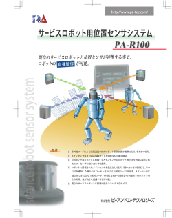
This series of inductors succeed in much lower flux leakage than a traditional sheild structure.
(It is suitable for using at a flux leakage impact)
Application : Car navigation system, Digital camera.
*/ T125 of operating temperature limit is to 125℃
従来の閉磁構造タイプよりもさらに漏れ磁束が少ない構造設計。
カーナビケーションや一眼レフカメラなど漏れ磁束が影響を及ぼす箇所に最適です。
CDPH49D19/HP
NEW
(including self-heating)
*/T125は使用温度範囲125℃まで(自己発熱含む)
DIMENSIONS (mm)
LAND PATTERNS (mm)
外形寸法図
推奨ランド寸法
Max. 2.0
7
7. 5
3.
1
2.
PROVISIONAL
1.
8
Max. 5.1
4
1.
5.
3. 0
6
Max. 5.1
Power Inductors < Low Leakage Flux Type >
Low Leakage Flux Type
CDMPIH58D28
LAND PATTERNS (mm)
DIMENSIONS (mm)
推奨ランド寸法
外形寸法図
Max. 3.2
5.8
3.8
1.4
3.5
1.4
2.8
5.8
5.8±0.2
5.8±0.2
2.5
NEW
PROVISIONAL
LAND PATTERNS (mm)
外形寸法図
推奨ランド寸法
Max. 5.0
1.8
1.8
4.3
Max. 6.6
3.6
Max. 6.2
1.8
DIMENSIONS (mm)
1.0
CDMPIH60D48/T125
2.2
PROVISIONAL
LAND PATTERNS (mm)
DIMENSIONS (mm)
CDMPIH75D43/T125
推奨ランド寸法
2.0
2.0
Max. 4.5
2.0
5.0
Max. 8.1
4.6
Max. 7.7
1.4
外形寸法図
PROVISIONAL
2.4
LAND PATTERNS (mm)
外形寸法図
推奨ランド寸法
Max. 5.0
3.4
2.2
7.2
Max. 10.7
6.8
Max. 10.3
2.2
DIMENSIONS (mm)
1.6
CDMPIH10D48/T125
PROVISIONAL
3.6
Specifications / 仕様
*1
*2
*3
*1
*2
*3
Saturation Current (A)
(at 20˚C) *1
1.75 - 3.1 *2
Temperature Rise Current (A) *3
Type Name
Inductance
型名
インダクタンス
CDPH49D19/HP
3.0µH - 10µH ± 20%
90m - 220m
CDMPIH58D28
150µH - 2.2mH ± 20%
850m - 13.2
85m - 330m
120m - 440m
CDMPIH60D48/T125
3.9µH - 6.2µH ± 25%, 10µH -100µH ± 20%
27m - 368m
800m - 4.1
850m - 3.5
CDMPIH75D43/T125
4.7µH - 6.8µH ± 25%, 10µH - 220µH ± 20%
22m - 805m
650m - 4.4
500m - 3.6
CDMPIH10D48/T125
4.3µH - 7.5µH ± 25%, 11µH -100µH ± 20%
15m - 220m
1.55 - 7.4
1.25 - 5.5
D.C.R.(Ω) : Typ.
直流重畳許容電流 (A)
温度上昇実力電流 (A)
980m - 1.42
Saturation Current : This indicates the value of D.C. current when the inductance becomes 35% lower than its nominal value.
Saturation Current : This indicates the value of D.C. current when the inductance becomes 30% lower than its nominal value.
Temperature Rise Current : The actual current when temperature of coil becomes ∆T=40°C (Ta=20°C ).
直流重畳許容電流:直流電流を流した時、
インダクタンスが公称値の65%以上となる電流値とする。
直流重畳許容電流:直流電流を流した時、
インダクタンスが公称値の70%以上となる電流値とする。
温度上昇実力電流:直流電流を流した時、
コイルの温度上昇がΔT= 40℃となる電流の実力値とする。
(Ta=20℃)
About CDPH49D19/HP, CDMPIH58D28, CDMPIH60D48/T125, CDMPIH75D43/T125, CDMPIH10D48/T125
This specification might be changed without notice due to under developing and improving. Please contact us
for our mass production schedule.Thank you for your understanding.
本仕様は開発中につき、製品の改善等により記載内容を予告なく変更することがありますので、
ご了承下さい。量産時期についてはお問合せ下さい。
15
Power Inductors < For Automotive Application >
Power Inductors SMD Shielded Type
(車載向け高温対応インダクタ)
Recommended Automotive Application Type Withstand up to 125˚C (including self-heating)
OUTLINE
/ 概要
Operational Ambient Temperature : -40°C~125°C(including self-heating up to 125°C)
Automotive reliability comply with AEC-Q200 standard.
It is the power inductor for automotive DC/DC converter application with revised and restudied structure and material from existing products.
使用温度範囲:-40℃∼125℃(コイル自己発熱含む)
車載信頼性基準 AEC-Q200準拠
従来品の構造、材料を見直し、高温・高信頼性要求に対応。
CDRH5D28R/H125
DIMENSIONS (mm)
LAND PATTERNS (mm)
CONNECTION
外形寸法図
推奨ランド寸法
端子接続
Max.6.2
2.0
ax
3.7
.8 .
1.4
M
0.9
4.1
Max.6.3
0.9
Max.3.0
1.4
Power Inductors < For Automotive Application >
CDRH**D**/T125 Series
(1.0µH - 10µH)
(15µH - 100µH)
2
2.2
DIMENSIONS (mm)
LAND PATTERNS (mm)
CONNECTION
外形寸法図
推奨ランド寸法
端子接続
Max.7.0
6.5
2.0
6.5
Max.7.0
2.65
Max.4.0
.5
.9
ax
M
CDRH8D43R/T125
2.0
7.3
CDRH6D38/T125
(3.0µH - 15µH)
DIMENSIONS (mm)
LAND PATTERNS (mm)
CONNECTION
外形寸法図
推奨ランド寸法
端子接続
Max.8.3
3.0
1.8
5.3
1.8
1.2
5.7
Max.8.5
1.2
Max.4.5
5
1.
.1
ax
M
(1.0µH - 10µH)
DIMENSIONS (mm)
LAND PATTERNS (mm)
CONNECTION
外形寸法図
推奨ランド寸法
端子接続
Max.4.0
5
3.
.1
ax
M
1.6
7.3
1.6
1.2
7.7
3.0
Max.10.5
Max.10.3
(1.5µH - 10µH)
(15µH - 33µH)
3.2
Inductance Range / インダクタンス範囲
CDRH5D28R/H125
1.0µH - 100µH
CDRH6D38/T125
3.0µH - 100µH
CDRH8D43R/T125
1.0µH - 330µH
CDRH104R/T125
1.5µH - 330µH
Measuring Freq.(L)100kHz / インダクタンス測定周波数100kHz
NOTE / 特記事項
Please note that when using the product for automotive while applying current with audio-frequency (AF) signals may result in audible noises due to magnetostriction.
Also, in order to avoid an audible noise problem, operating with Non-AF signals would be recommended.The noise may amplify depending on the coil mount area on the PCB.
車載向け製品に可聴周波数を含んだ電流を流すと磁歪現象によるうなりが生じ、
うなり音が聞こえる場合がありますので、
うなり音が問題となるような用途で御使用の場合は、
可聴周波数及び可聴周波数成分を含んだ電流を流さないようにして下さい。また、御使用基板での搭載場所によっては、
うなり音を増幅させる可能性もありますので御注意下さい。
16
(15µH - 330µH)
3.4
1.2
CDRH104R/T125
(22µH - 100µH)
7.3
(47µH - 330µH)
Power Inductors < For Automotive Application >
DIMENSIONS (mm)
LAND PATTERNS (mm)
外形寸法図
推奨ランド寸法
Max.4.8
2.5
5.6
2.0
6.0
2.5
2.0
0.1
DIMENSIONS (mm)
LAND PATTERNS (mm)
CONNECTION
外形寸法図
推奨ランド寸法
端子接続
Max. 7.0
4.0
6.6
2.0
1.5
5
3.
.1
ax
M
(1.5µH - 10µH)
(15µH - 1.0mH)
4.4
DIMENSIONS (mm)
LAND PATTERNS (mm)
CONNECTION
外形寸法図
推奨ランド寸法
端子接続
5.0
Max.6.0
5.4
7.6
12.0
Max12.3
7.0
12.8
Max.12.3
2.9
CDRH125/L125
7.0
Max.10.4
1.5
Max.10.4
2.0
CDRH10D68R/T125
3.2
3.0
Max.10.4
Max.10.4
Power Inductors < For Automotive Application >
CDRR105
(1.2µH - 47µH)
Solder Resist
0.2
(68µH - 1.0mH)
* In order to prevent short-circuiting, a solder resist is recommended.
ソルダレジスト推奨
* ショート防止の為、
CDRH127/L125
DIMENSIONS (mm)
LAND PATTERNS (mm)
CONNECTION
外形寸法図
推奨ランド寸法
端子接続
Max.12.3
5.4
5.0
7.0
12.8
7.6
12.0
Max12.3
2.9
Max.8.0
(2.7µH - 47µH)
(68µH - 150µH)
(220µH - 1.0mH)
Solder Resist
0.2
CDRR126
* In order to prevent short-circuiting, a solder resist is recommended.
ソルダレジスト推奨
* ショート防止の為、
DIMENSIONS (mm)
LAND PATTERNS (mm)
外形寸法図
推奨ランド寸法
Max.6.8
3.2
3.0
2.5
2.5
8.1
8.5
Max.12.8
2.0
Max.12.8
0.1
Inductance Range / インダクタンス範囲
CDRH104R/T125
1.5µH - 330µH
CDRR105
CDRH10D68R/T125
1.5µH - 1.0mH
CDRR126
CDRH125/L125
1.2µH - 1.0mH
CDRH127/L125
2.7µH - 1.0mH
3.3µH - 1.5mH
7.0µH-330µH
Measuring Freq.(L)1kHz / インダクタンス測定周波数1kHz
Measuring Freq.(L)100kHz / インダクタンス測定周波数100kHz
NOTE / 特記事項
Please note that when using the product for automotive while applying current with audio-frequency (AF) signals may result in audible noises due to magnetostriction.
Also, in order to avoid an audible noise problem, operating with Non-AF signals would be recommended.The noise may amplify depending on the coil mount area on the PCB.
車載向け製品に可聴周波数を含んだ電流を流すと磁歪現象によるうなりが生じ、
うなり音が聞こえる場合がありますので、
うなり音が問題となるような用途で御使用の場合は、
可聴周波数及び可聴周波数成分を含んだ電流を流さないようにして下さい。また、御使用基板での搭載場所によっては、
うなり音を増幅させる可能性もありますので御注意下さい。
17
Power Inductors < For Automotive application>
Power Inductors SMD Shielded Type
Power Inductors < For Automotive application >
CDEP**ME
(車載向け高温対応インダクタ)
High-temp power inductor for automotive application
OUTLINE
/ 概要
Large current SMD power inductor with dust core.
Compliance with AEC-Q200 reliability test condition & TS16949 quality management system
Operational temperature range: - 40°C~+125°C(excluding self-heating)
Application : Boost converter for idling stop system and large current filter
DUSTコアを用いた大電流タイプSMDパワーインダクタ。
AEC-Q200信頼性試験準拠、TS16949品質マネージメント対応。
使用温度範囲:-40℃∼+125℃(コイル自己発熱含まず)
アイドリングストップ向け昇圧電流、各種大電流フィルターに最適。
CDEP125MEB
DIMENSIONS (mm)
LAND PATTERNS (mm)
CONNECTION
外形寸法図
推奨ランド寸法
端子接続
Max.12.9
3.3
4.0 4.6
Max. 5.5
4.0
7.0
10.0
2.3
2
3
1
2.6
2.1
Max.12.9
2.6
2.0
3.8 4.4
BOTTOM VIEW
13.5
裏面図
DIMENSIONS (mm)
LAND PATTERNS (mm)
CONNECTION
外形寸法図
推奨ランド寸法
端子接続
PROVISIONAL
CDEP147ME
NEW
Max.8.0
2.1
9.0
2.6
2.4
6.0
12.0
10.5
2.6
Max.14.9
Max.14.9
2
3
1
10.2
15.5
BOTTOM VIEW
裏面図
PROVISIONAL
Inductance Range / インダクタンス範囲
CDEP125MEB
0.3µH - 6.0µH
CDEP147ME
0.56µH - 10µH
Measuring Freq.(L)100kHz / インダクタンス測定周波数100kHz
NOTE / 特記事項
* Please do not use a washing agent.
* Please put the solder to all terminal whenever you use this coil.
* Please pay attention to the suitability of the pattern for the current in design.
* Please pay attention to safety distance between coil periphery and other parts or copper pattern, because dust core in used in the products.
* 洗浄は、お避け下さい。
* 全端子はんだ付けをして御使用下さい。
* 使用電流に合ったパターン設計をお願い致します。
* 本製品は、鉄系コアを使用しているため、コイルの外周面と他の部品及び、銅パターンとの距離は安全上、十分な距離を確保して御使用下さい。
About CDEP125MEB, CDEP147ME
This specification might be changed without notice due to under developing and improving. Please contact us for our mass production schedule.Thank you for your understanding.
本仕様は開発中につき、製品の改善等により記載内容を予告なく変更することがありますので、
ご了承下さい。量産時期についてはお問合せ下さい。
18
Power Inductors for LED lighting
Power Inductors
OUTLINE
/ 概要
Operational Ambient Temperature : -40°C~125°C(including self-heating)
LED drive power inductors are applicable for input AC100V high withstand voltage needs & other inductors for high L values chokes used in
output filter needs standrdized with small footprit, low profile and cost-competitive feature.
使用温度範囲:-40∼125℃(コイル自己発熱含み)
入力AC100Vに対応した耐電圧LED駆動用電源インダクタ、及び各種LED電球の電流値ニーズに対応した出力平滑用ハイL値インダクタを小型、低背、廉価でシリーズ化しました。
CDRH5D11
DIMENSIONS (mm)
LAND PATTERNS (mm)
外形寸法図
推奨ランド寸法
1.
4
Max.1.2
Max.5.3
1.
0
Max.5.3
Power Inductors for LED lighting
DC/DC converter inductors &
output filter chokes for LED lighting
5
3. .6
6
8
3. .8
5
DIMENSIONS (mm)
LAND PATTERNS (mm)
外形寸法図
推奨ランド寸法
Max.5.0
5.6
1.0 2.3
4.2
1.2
4.0
Max.5.9
Max.5.15
5.4
CDH50D48
PROVISIONAL
DIMENSIONS (mm)
LAND PATTERNS (mm)
外形寸法図
推奨ランド寸法
Max.7.9
7.2
1.3 2.95
5.8
1.5
7.0
Max.5.0
Max.7.15
5.6
CDH70D48
PROVISIONAL
Inductance Range / インダクタンス範囲
CDRH5D11
CDH50D48
CDH70D48
1.0µH - 22µH
100µH - 4.7mH
100µH - 4.7mH
Measuring Freq.(L)100kHz / インダクタンス測定周波数100kHz
About CDH50D48, CDH70D48
This specification might be changed without notice due to under developing and improving. Please contact us for our mass production schedule.Thank you for your understanding.
本仕様は開発中につき、製品の改善等により記載内容を予告なく変更することがありますので、
ご了承下さい。量産時期についてはお問合せ下さい。
19
Power Inductors for LED lighting
LAND PATTERNS (mm)
外形寸法図
Max.8.15
推奨ランド寸法
8.0
1.3 3.35
6.6
1.5
Max.5.0
6.4
7.8
NEW
NEW
DIMENSIONS (mm)
Max.8.9
Power Inductors for LED lighting
CDH80D48
PROVISIONAL
RPT109
DIMENSIONS (mm)
CONNECTION
外形寸法図
端子接続
NEW
Max.10.5
5.6
3.5
5.6
Max.10.5
ø0.6
Max.10.0
2
3
1
4
BOTTOM VIEW
裏面図
PROVISIONAL
DIMENSIONS (mm)
CONNECTION
外形寸法図
端子接続
Max.10.0
3.5
Max.12.5
ø0.7
Max.12.5
6.8
6.8
RPT129
2
3
1
4
BOTTOM VIEW
裏面図
PROVISIONAL
Inductance Range / インダクタンス範囲
CDH80D48
RPT109
RPT129
100µH - 4.7mH
560µH - 2.0mH
560µH - 2.0mH
Measuring Freq.(L)100kHz / インダクタンス測定周波数100kHz
About CDH80D48, RPT109, RPT129
This specification might be changed without notice due to under developing and improving. Please contact us for our mass production schedule.Thank you for your understanding.
本仕様は開発中につき、製品の改善等により記載内容を予告なく変更することがありますので、
ご了承下さい。量産時期についてはお問合せ下さい。
20
Chip Inductor
OUTLINE
Chip Inductor
Chip Inductor
/ 概要
Winding type chip inductor of 4532 size.
4352サイズの巻線型チップインダクタ。
DIMENSIONS (mm)
LAND PATTERNS (mm)
外形寸法図
結線図
4.0
Max. 3.0
S
1.0
Min. 1.0
Min. 1.0
Min. 1.0
Max. 4.8
Max. 3.5
SCHEMATICS
推奨ランド寸法
R1.0
5.0
CSLF3226B
F
Solder Resist
BOTTOM VIEW
/ 裏面図
* In order to prevent short-circuiting, a solder resist is recommended.
* ショート防止の為、
ソルダレジスト推奨
• Features / 特徴
• The chip inductor CSLF3226B series consists of miniature chip inductors
wound on a special ferrite core.
• It has a high Q value at high frequencies and low DCR.
• Apply for mini-type power circuit and signal circuit.
• Low THD for signal circuit.
・ 特殊コアに巻線したCSLF3226Bシリーズの小型チップインダクタです。
・ ハイQです。
・ 小型電源回路や信号回路に最適です。
・ 信号回路に対して低歪率です。
Specifications / 仕様
Part No.
Inductance
部品番号
インダクタンス
CSLF3226B-1R0MC
CSLF3226B-1R2MC
CSLF3226B-1R5MC
CSLF3226B-1R8MC
CSLF3226B-2R2MC
CSLF3226B-2R7MC
CSLF3226B-3R3MC
CSLF3226B-3R9MC
CSLF3226B-4R7KC
CSLF3226B-5R6KC
CSLF3226B-6R8KC
CSLF3226B-8R2KC
CSLF3226B-100KC
CSLF3226B-120KC
CSLF3226B-150KC
CSLF3226B-180KC
CSLF3226B-220KC
CSLF3226B-270KC
CSLF3226B-330KC
CSLF3226B-390KC
CSLF3226B-470KC
CSLF3226B-560KC
CSLF3226B-680KC
CSLF3226B-820KC
CSLF3226B-101KC
CSLF3226B-121KC
CSLF3226B-151KC
CSLF3226B-181KC
CSLF3226B-221KC
CSLF3226B-271KC
CSLF3226B-331KC
CSLF3226B-391KC
CSLF3226B-471KC
CSLF3226B-561KC
CSLF3226B-681KC
CSLF3226B-821KC
CSLF3226B-102KC
CSLF3226B-122KC
CSLF3226B-152KC
CSLF3226B-182KC
CSLF3226B-222KC
1.0µH ± 20%
1.2µH ± 20%
1.5µH ± 20%
1.8µH ± 20%
2.2µH ± 20%
2.7µH ± 20%
3.3µH ± 20%
3.9µH ± 20%
4.7µH ± 10%
5.6µH ± 10%
6.8µH ± 10%
8.2µH ± 10%
10µH ± 10%
12µH ± 10%
15µH ± 10%
18µH ± 10%
22µH ± 10%
27µH ± 10%
33µH ± 10%
39µH ± 10%
47µH ± 10%
56µH ± 10%
68µH ± 10%
82µH ± 10%
100µH ± 10%
120µH ± 10%
150µH ± 10%
180µH ± 10%
220µH ± 10%
270µH ± 10%
330µH ± 10%
390µH ± 10%
470µH ± 10%
560µH ± 10%
680µH ± 10%
820µH ± 10%
1000µH ± 10%
1200µH ± 10%
1500µH ± 10%
1800µH ± 10%
2200µH ± 10%
D.C.R
Max. 0.20Ω
Max. 0.20Ω
Max. 0.30Ω
Max. 0.30Ω
Max. 0.30Ω
Max. 0.32Ω
Max. 0.35Ω
Max. 0.38Ω
Max. 0.40Ω
Max. 0.48Ω
Max. 0.50Ω
Max. 0.56Ω
Max. 0.56Ω
Max. 0.62Ω
Max. 0.73Ω
Max. 0.82Ω
Max. 0.94Ω
Max. 1.10Ω
Max. 1.20Ω
Max. 1.40Ω
Max. 1.50Ω
Max. 1.70Ω
Max. 1.90Ω
Max. 2.20Ω
Max. 2.50Ω
Max. 3.00Ω
Max. 3.70Ω
Max. 4.50Ω
Max. 5.40Ω
Max. 6.80Ω
Max. 8.20Ω
Max. 9.70Ω
Max. 11.8Ω
Max. 14.5Ω
Max. 17.0Ω
Max. 20.5Ω
Max. 25.0Ω
Max. 30.0Ω
Max. 37.0Ω
Max. 45.0Ω
Max. 50.0Ω
Unloaded Q
無負荷Q
Min. 20
Min. 20
Min. 20
Min. 20
Min. 20
Min. 20
Min. 20
Min. 20
Min. 30
Min. 30
Min. 30
Min. 30
Min. 35
Min. 35
Min. 35
Min. 35
Min. 35
Min. 35
Min. 35
Min. 35
Min. 35
Min. 35
Min. 35
Min. 35
Min. 40
Min. 40
Min. 40
Min. 40
Min. 40
Min. 40
Min. 40
Min. 40
Min. 40
Min. 40
Min. 40
Min. 40
Min. 40
Min. 40
Min. 40
Min. 40
Min. 40
Self Resonance
Frequency
Rated Current
Measuring Condition
自己共振周波数
定格電流
測定条件
Min. 120MHz
Min. 100MHz
Min. 85MHz
Min. 75MHz
Min. 62MHz
Min. 53MHz
Min. 47MHz
Min. 41MHz
Min. 38MHz
Min. 36MHz
Min. 31MHz
Min. 27MHz
Min. 23MHz
Min. 21MHz
Min. 19MHz
Min. 17MHz
Min. 15MHz
Min. 14MHz
Min. 12MHz
Min. 11MHz
Min. 10MHz
Min. 9.3MHz
Min. 8.4MHz
Min. 7.5MHz
Min. 6.8MHz
Min. 6.2MHz
Min. 5.5MHz
Min. 5.0MHz
Min. 4.5MHz
Min. 4.0MHz
Min. 3.6MHz
Min. 3.3MHz
Min. 3.0MHz
Min. 2.7MHz
Min. 2.5MHz
Min. 2.2MHz
Min. 2.0MHz
Min. 1.8MHz
Min. 1.6MHz
Min. 1.5MHz
Min. 1.3MHz
500mA
500mA
500mA
500mA
500mA
500mA
500mA
500mA
500mA
500mA
450mA
450mA
400mA
380mA
360mA
340mA
320mA
300mA
270mA
240mA
220mA
200mA
180mA
170mA
160mA
150mA
130mA
120mA
110mA
100mA
95mA
90mA
80mA
70mA
65mA
60mA
50mA
45mA
40mA
35mA
30mA
Condition A
Condition A
Condition A
Condition A
Condition A
Condition A
Condition A
Condition A
Condition A
Condition A
Condition A
Condition A
Condition A
Condition A
Condition A
Condition A
Condition A
Condition A
Condition A
Condition A
Condition A
Condition A
Condition A
Condition A
Condition B
Condition B
Condition B
Condition B
Condition B
Condition B
Condition B
Condition B
Condition B
Condition B
Condition B
Condition B
Condition C
Condition C
Condition C
Condition C
Condition C
Notes :
1. Measuring condition A : Inductance measuring at 1MHz, 0.1Vrms, Qu measuring at 1MHz, 0.1Vrms, 1.0µH ~ 82µH
2. Measuring condition B : Inductance measuring at 1MHz, 0.1Vrms, Qu measuring at 796kHz, 0.1Vrms, 100µH ~ 820µH
3. Measuring condition C : Inductance measuring at 1kHz, 0.1Vrms, Qu measuring at 252kHz, 0.1Vrms, 1000µH ~ 2200µH
4. Rating current : this indicates the value of current when the inductance is 10% lower than its initial value at DC superposition of DC current when ∆T=40°C whichever is lower.(Ta=20°C)
5. Operating temperature range : -25°C ~ 85°C.
21
DC-DC Converter Transformer
/ DC-DC コンバータ
DC-DC Converter Transformer
DC-DC Converter Transformer
1. Classification of DC-DC Converter Transformer
A. Oscillation Configuration
■ Flyback Configuration (On-Off type)
Transformer can be configured to have multiple outputs. Fewer
components are needed and design is easier to implement.
■ Forward Configuration (On-On type)
Forward Configuration will perform twice as much of wattage output
when compared to Flyback.
B. Driving
■ R. C. C.
Frequency is dependent on the input voltage and load fluctuation.
Circuit design is easier and inexpensive, but noise radiation is larger.
■ IC controlled type
PWM (Pulse Width Modulation) is one common method.
PFM (Pulse Frequency Modulation) is an excellent method to improve
efficiency and prevents the discontinuous oscillation under the condition
of light load. The output voltage stability is very good.
C. Single output/Multiple outputs
■ Single output
It can be designed the chopper circuit with inductor.
It is inexpensive, high efficiency and a smaller footprint. However, it is
not suitable for the application for large voltage gap between primary and
secondary, step up & step (hybrid) type, and isolation type.
■ Multiple outputs
You have an option of designing our transformers with multiple
outputs. When considered feedback (From Secondary output to
Primary Input), it's recommended that you select the output that has
the largest wattage.
D. DC-DC CONVERTER BASIC CIRCUIT
Ringing choke method
(fry back)
Forward method
Chopper method
Ferrite Material
Frequency Range
Power Density
Price
Mn-Zn
∼1MHz
Large
Expensive
Low
Ni-Zn
∼300MHz
Small
Imexpensive
High
Resistivity
We classify the ferrite core into two types, one is manganese and the
other is nickel types. Manganese core for DC-DC can operate up to 1MHz.
Nickel core for DC-DC can operate from 2MHz to 3MHz. The suitable
frequency for nickel core type is 2MHz,3MHz. The maximum frequency in
which the nickel core can operate is 300MHz. The nickel core type has a
lower cost and is suitable for the chopper circuit.
B. Wire
The polyurethane copper wire has traditionally been used for
transformers.The reason why we prefer to use the polyurethane copper
wire is that it efficiently works better because of the ability to melt down
the polyurethane by solder temperature.
Please be advised that we may use various polyurethane copper wire
that are classified by the thickness of the wire.They are classified as wire
class 0, 1, 2, and 3. class 0 is the thinnest wire, while our class 3 is the
thickest.
When using thinner wire, higher inductance will be achieved by winding
many turns in the same winding space. Additionally, when using a thicker
wire, you will get the higher isolation voltage.
① Wire class 2 is a standard type.
② Wire class 3 is normally used in signal filter application.
③ Wire class 1 is normally used in power supply transformer application.
If a higher reliability is required, we recommend you to use the wire class
0 or the polyamide covered copper wire.
The temperature grades of the wire are also classified as follows;
Wire Class A
Wire Class E
Wire Class B
Wire Class F
PWM
PWM
2. Construction Materials
A. Ferrite
Advantages for using Manganese Versus Nickel Ferrite Core
:
:
:
:
105˚C
120˚C
130˚C
155˚C
C. Glue
The types of glue that we use on our products are Epoxy and UV hard type
glues. UV type is superior for using in higher heat environments.
Due to the different heating points of contraction and expansion rates
between ferrite core and base (bobbin), cracks may occur within the glue.
To ensure not to occur this situation, it's important that our products don't
exceed our specifications for operating and storage temperature.
E. Please show us items below when ordering
1. Operating conditions.
2. Type of request.
3. Electrical specifications.
Input voltage DC ± V∼ V (Typ. V)
Item
Min. Typ. Max.
Output current (mA)
Min. Typ.
Max.
Max. Output power
V1 (AC, +. −)
Output
voltage
V2 (AC, +. −)
V3 (AC, +. −)
V4 (AC, +. −)
・Kinds of power supply.
・Method of circuit.
・Semiconductor of use.
F. Maximum power in this catalog works out the method below.
Flyback method Vin :+12V
+B
3. Core structure
We use manganese core (EE type) and nickel core (drum & ring type).
As manganese core is better efficiency, so we can design a transformer
using a smaller platform to achieve an overall smaller footprint.
The manganese core can achieve good characteristics of DC-DC
converter. Due to the manganese conductivity, we can't wind directly
around the core. Thus the plastic bobbin is required.
It will increase cost, but we are able to design the magnetically shielded
type for noise reduction.
Regarding drum and ring type, we can directly wind to the drum core.
It is inexpensive for transformer design because the core is a lower cost.
Core structure
Core material
Dimensions
Efficiency
Price
EE
Mn-Zn
○
○
△
Drum+Ring
Ni-Zn
△
△
○
Winding space
RL
PWM
Vout :+12V Efficiency :75%
Maximum power is different depending on conditions.
22
EE core
Drum + Ring core
EE core type is completely shielded magnetically.
Drum and ring core type have the magnetic flux due to the having core gap.
DC-DC Converter Transformer
2. 構成材料
A. 発振方式
A. フェライト
■ フライバック方式
フェライトコアを大きく分類するとマンガン系とニッケル系に分かれます。
多出力が可能な一般的なタイプです。部品点数が少なく制御が簡単です。
■ フォアード方式
最大電力がフライバック方式に比べて約2倍扱うことが可能です。
B. 駆動方法
■ 他励式
PWM(パルス幅変調)方式が一般的です。
軽負荷時の効率向上と間欠発振防止に優れたPFM(パルス周波数変調)方式もあ
ります。出力電圧の安定度が良くなります。
C. 単出力・多出力
■ 単出力
チョッパー方式の採用が可能です。2端子インダクタで回路構成可能(自励式は
4端子)です。
高効率、小型で廉価です。変圧比が大きい仕様や昇降圧併用タイプ、絶縁タイプは
出来ません。
■ 多出力
トランスの出力巻き線よりタップを取って多出力が可能。
出力電力の一番大きい端子からフィードバックを掛けると安定します。
(フライバック)
低い
Ni-Zn
∼300MHz
小
廉価
高い
B. 電線
トランスには通常ポリウレタン皮膜銅線が使用されています。
理由は絶縁皮膜が半田温度により溶解するため作業効率に優れるためです。
ポリウレタン皮 膜 銅 線には皮 膜 厚さにより、0 種、1 種、2 種、3 種に分 類されていま
す。数字が大きくなれば皮膜が薄くなります。
皮膜が薄ければ、同じ巻き枠で多く巻けるため高インダクタンスが得られます。逆に
皮膜が厚ければ、高耐圧にする事が可能です。
① 2種線がスタンダードタイプです。
② 3種線は主に信号系フィルタに使用されます。
③ 1種線は電源系トランスに使用されます。
フェライトコアとベ ース(ボビン)の 熱収縮率が違うためクラックが発 生し易くなる
ため十分な検討が必要です。
エポキシ系、UV硬化系があります。UV硬化系は硬化しても粘性があるため熱収縮率
の異なる材料の接着に適しています。
1. 使用環境
2. 希望形名
3. 電気的特性
3. 磁気構造
入力電圧 DC ± V∼ V (Typ. V)
Min. Typ. Max.
負荷電流範囲
Min. Typ.
Max.
最大出力電力
V1 (AC, +. −)
出力電力
固有抵抗
高価
C. 接着剤
PWM
E . トランスの依頼をされる場合は下記項目をご提示下さい。
項目
価格
大
A種 : 105℃
E種 : 120℃
B種 : 130℃
F種 : 155℃
チョッパー方式
PWM
電力密度
更に高信頼性を要求される場合は、0種線又はポリアミド皮膜銅線などが使用されます。
また、電線の耐熱グレードは以下の様に分類されます。
D. DC-DCコンバータ基本回路図
フォワード方式
適応周波数
∼1MHz
マンガン系コアの適応周波数は上限1MHz程度ですが、最近の発振周波数のトレンド
は1MHzに近づいています。
ニッケル系コアの適応周波数は、2MHz∼3MHzです。
( 高周波信号を扱うコアは
300MHz程度です。)ニッケル系コアは廉価でチョッパー方式に適しています。
■ 自励式(R.C.C.)
入力電圧や負荷変動により周波数が変動します。
回路構成が簡単なので安価に出来ますが、
ノイズは広帯域で放射されます。
リンギングチョーク方式
コア材料
Mn-Zn
DC-DC Converter Transformer
1. DC-DCコンバータの分類
/ DC-DC コンバータ
V2 (AC, +. −)
コアを 大きく分 類 するとマンガン系 E Eタイプとニッケル 系ドラム・リングタイプに
分かれます。前者はコアの特性から効率が良く、小型にすることが可能です。
マンガン系コアは導電性があり、コアに直接巻き線する事が出来ません。
従って、ボビンに巻き線をするため製造工程が増えコスト高になります。
但し、構造上閉磁路に設計できるためノイズ低減が可能です。
ドラム・リングタイプは、
ドラムコアに直接巻き線が可能です。
また、コアが安価ですのでトランスも廉価に設計可能です。
V3 (AC, +. −)
磁気構造
コア材料
外形寸法
効率
コスト
V4 (AC, +. −)
EE
Drum+Ring
Mn-Zn
○
○
△
Ni-Zn
△
△
○
・使用電源
・回路方式
・使用半導体
巻線部
F. カタログ中の最大容量は下記の方法により算出したものです。
+B
RL
PWM
EE core
Drum + Ring core
EEコアタイプはほぼ完全な閉磁路設計が可能です。
ドラム・リングコアタイプは、エアギャップが発生するため磁束が外部に漏れます。
フライバック方式入力電圧:+12V 出力電圧:+12V 効率:75%
最大容量は使用条件により異なります。
23
DC-DC Converter Transformers < Transformers for UP-Down or Up Converter >
DC-DC Converter Transformers
Transformers for UP-Down or Up Converter
/ 概要
This is small size and high efficient up-down converter transformer which is 2 in 1 construction. (ex. SEPIC converter)
It is possible to output the high voltage which is hard to obtain with an ordinary inductor with sufficient accuracy.
It is available for a white LED back light drive.
2in1構造の小型・高効率のSEPIC、ZETAコンバータ用トランスです。通常のインダクタでは得にくい大きい昇圧比にて、巻上トランスとして使用する事が可能です。
DSC、
ノートPC、DVC用の電源。白色LEDバックライト駆動用の電源に最適です。
CLS4D18
LAND PATTERNS (mm)
DIMENSIONS (mm)
外形寸法図
1.5
2.8
0.7
Application / 用途
CONSTRUCTION
磁気構造図
3.1
2.0
5.3
3.4
0.9
0.50
Max. 5.1
Max. 2.0
端子接続
0.7
Max. 5.0
CONNECTION
推奨ランド寸法
Max. 5.0
2
3
1
4
BOTTOM VIEW
/ 裏面図
1. The power supply for DSC, Note PC and DVC
1. DSC、ノートパソコン、DVC用電源
CLS4D23B
LAND PATTERNS (mm)
DIMENSIONS (mm)
外形寸法図
4.6
1.8
Max. 5.0
CONNECTION
端子接続
CONSTRUCTION
磁気構造図
0.9 2.0
2.4 1.2
Max. 2.5
Max. 4.8
推奨ランド寸法
1.6
4.9
MAX.6.0
DC-DC Converter Transformers < Transformers for UP-Down or Up Converter >
OUTLINE
2
3
1
4
BOTTOM VIEW
/ 裏面図
Application / 用途
1. The power supply for DSC, Note PC and DVC
1. DSC、ノートパソコン、DVC用電源
CLS4D28B
LAND PATTERNS (mm)
DIMENSIONS (mm)
外形寸法図
4.6
1.8
2.4 1.2
Max. 5.0
CONNECTION
端子接続
CONSTRUCTION
磁気構造図
0.9 2.0
1.6
4.9
MAX.6.0
Max. 3.0
Max. 4.8
推奨ランド寸法
2
3
1
4
BOTTOM VIEW
/ 裏面図
Application / 用途
1. The power supply for DSC, Note PC and DVC
1. DSC、ノートパソコン、DVC用電源
CLS6D18
LAND PATTERNS (mm)
DIMENSIONS (mm)
外形寸法図
CONNECTION
端子接続
3
1
4
2.8
2
BOTTOM VIEW
PROVISIONAL
CONSTRUCTION
2.1 1.9
2.3
Max. 7.0
5.5
2.5
3.6
6.6
Max. 8.3
Max. 2.0
Max. 7.0
推奨ランド寸法
/ 裏面図
Application / 用途
1. The power supply for DSC, Note PC and DVC
1. DSC、ノートパソコン、DVC用電源
About CLS6D18
This specification might be changed without notice due to under developing and improving. Please contact us for our mass production schedule.Thank you for your understanding.
本仕様は開発中につき、製品の改善等により記載内容を予告なく変更することがありますので、
ご了承下さい。量産時期についてはお問合せ下さい。
24
磁気構造図
DC-DC Converter Transformers < Transformers for UP-Down or Up Converter >
TYPE : CLS4D18, CLS4D23B
CLS4D18
CLS4D23B
L
(H)
1R0
1.0µ
2.4
1.7
1.2
860m
3.0
1.5
1R8
1.8µ
1.7
1.3
870m
650m
2.7
1.2
2R2
2.2µ
1.5
1.1
720m
560m
2.4
1.1
3R3
3.3µ
1.2
880m
630m
470m
2.3
900m
3R6
3.6µ
5R0
5.0µ
1.2
770m
500m
360m
1.8
700m
5R3
5.3µ
6R8
6.8µ
860m
650m
430m
310m
1.6
650m
7R3
7.3µ
100
10µ
680m
520m
330m
260m
1.2
470m
110
170
220
Saturation Current (A)
2-4, 1-3
2-3 (1-4tie)
Condition1*A Condition2*B Condition3*A Condition4*B
Saturation Current (A)
2-4, 1-3
2-3 (1-4tie)
Condition1*A Condition2*B Condition3*A Condition4*B
Temperature
Rise Current (A)*C
2-4, 1-3
2-3 (1-4tie)
Condition5
Condition6
2.4
1.9
1.1
900m
3.0
1.3
1.7
1.4
1.0
750m
2.4
1.1
1.5
1.1
720m
600m
2.0
850m
1.3
1.1
540m
450m
1.8
750m
11µ
900m
700m
470m
410m
1.6
620m
17µ
720m
650m
400m
300m
1.1
450m
22µ
570m
550m
270m
220m
1.1
430m
Tolerance of Inductance/ インダクタンス公差
CLS4D18
1.0µH-10.0µH±30%(N)
CLS4D23B
2.2µH-22.0µH±30%(N)
Measuring Freq: (L)/ インダクタンス測定周波数
CLS4D18
100kHz
CLS4D23B
100kHz
TYPE : CLS4D28B, CLS6D18
CLS4D28B
CLS6D18
Temperature
Rise Current (A)*C
Parts
No.
L
(H)
1R3
1.3µ
2.69
2.02
1.34
1R9
1.9µ
2.20
1.65
1.17
2R2
2.2µ
2R6
2.6µ
1.96
1.46
970m
3R5
3.5µ
1.72
1.29
770m
4R7
4.7µ
1.43
1.07
5R2
5.2µ
6R8
100
Saturation Current (A)
2-4, 1-3
2-3 (1-4tie)
Condition1*A Condition2*B Condition3*A Condition4*B
2-4, 1-3
Condition5
2-3 (1-4tie)
Condition6
1.80
1.35
900m
700m
2.40
1.20
1.40
1.10
700m
540m
2.10
1.00
Temperature
Rise Current (A)*C
Saturation Current (A)
2-4, 1-3
2-3 (1-4tie)
Condition1*A Condition2*B Condition3*A Condition4*B
2-4, 1-3
Condition5
2-3 (1-4tie)
Condition6
1.01
1.70
810m
880m
1.58
750m
730m
1.45
690m
580m
1.20
570m
700m
530m
1.05
500m
1.20
900m
600m
450m
1.80
880m
6.8µ
1.00
800m
500m
400m
1.50
720m
1.20
900m
580m
440m
810m
380m
10µ
850m
600m
420m
320m
1.30
630m
980m
740m
490m
370m
750m
360m
150
15µ
650m
500m
340m
250m
1.10
520m
900m
680m
380m
290m
550m
260m
220
22µ
550m
420m
280m
200m
950m
430m
630m
470m
300m
230m
350m
170m
330
33µ
450m
320m
220m
160m
800m
360m
470
47µ
400m
280m
180m
140m
750m
320m
Measuring Freq: (L)/ インダクタンス測定周波数
CLS4D28B
100kHz
CLS6D18
100kHz
Other
*A
*B
*C
*A
*B
*C
DC-DC Converter Transformers < Transformers for UP-Down or Up Converter >
Temperature
Rise Current (A)*C
2-4, 1-3
2-3 (1-4tie)
Condition5
Condition6
Parts
No.
Tolerance of Inductance/ インダクタンス公差
CLS4D28B
2.2µH-47.0µH±30%(N)
CLS6D18
1.3µH-22.0µH±30%(N)
/ その他
Saturation Current 1,3 : This indicates the value of D.C. current when the inductance decreases to 90% of its initial value.(Ta=20°C)
Saturation Current 2,4 : This indicates the value of D.C. current when the inductance decreases to 90% of its initial value.(Ta=100°C)
Temperature Rise Current 5,6 : The actual current when temperature of coil becomes Max.∆T=40°C.(Ta=20°C)
直流重畳許容電流1,3 : 直流電流を流した時、
インダクタンスが初期値の90%以上となる電流値とする。(Ta=20℃)
直流重畳許容電流2,4 : 直流電流を流した時、
インダクタンスが初期値の90%以上となる電流値とする。(Ta=100℃)
温度上昇実力電流5,6 : 直流電流を流した時、
コイルの温度上昇が△T=40℃以下となる電流の実力値とする。(Ta=20℃)
25
DC-DC Converter Transformers < Transformers for UP-Down or Up Converter >
CLS6D23
LAND PATTERNS (mm)
DIMENSIONS (mm)
外形寸法図
端子接続
CONSTRUCTION
磁気構造図
2.1 1.9
2
3
1
4
2.3
2.8
3.6
6.6
Max. 8.3
Max. 7.0
CONNECTION
BOTTOM VIEW
/ 裏面図
Application / 用途
1. The power supply for DSC, Note PC and DVC
1. DSC、ノートパソコン、DVC用電源
CLS6D28
LAND PATTERNS (mm)
DIMENSIONS (mm)
外形寸法図
CONNECTION
端子接続
CONSTRUCTION
磁気構造図
2.1 1.9
2.3
3.6
6.6
Max. 8.3
2
3
1
4
2.8
5.5
2.5
Max. 3.0
Max. 7.0
推奨ランド寸法
Max. 7.0
DC-DC Converter Transformers < Transformers for UP-Down or Up Converter >
5.5
2.45
Max. 2.5
Max. 7.0
推奨ランド寸法
BOTTOM VIEW
/ 裏面図
Application / 用途
1. The power supply for DSC, Note PC and DVC
1. DSC、ノートパソコン、DVC用電源
CLS7D14
LAND PATTERNS (mm)
DIMENSIONS (mm)
外形寸法図
Max. 7.3
推奨ランド寸法
Max. 1.5
CONNECTION
端子接続
CONSTRUCTION
磁気構造図
7.0
2
3
1
4
1
2.
5
7. .5
4
7.3
1.7
2.8
Max. 7.3
2.0 2.5
BOTTOM VIEW
/ 裏面図
Application / 用途
1. The power supply for DSC, Note PC and DVC
1. DSC、ノートパソコン、DVC用電源
LAND PATTERNS (mm)
DIMENSIONS (mm)
外形寸法図
6.7
2.45
端子接続
CONSTRUCTION
磁気構造図
2
3
1
4
4.0
Max. 9.0
CONNECTION
2.0 2.7
4.7
8.6
Max. 10.5
Max. 3.0
Max. 9.0
推奨ランド寸法
3.3
CLS8D28
BOTTOM VIEW
/ 裏面図
Application / 用途
1. The power supply for DSC, Note PC and DVC
1. DSC、ノートパソコン、DVC用電源
LAND PATTERNS (mm)
DIMENSIONS (mm)
外形寸法図
Application
1. The power supply for LCD TV and Car navigation
1. 液晶テレビ、カーナビ用の電源
26
CONNECTION
端子接続
1.3 3.6
4.0
Max. 10.2
8.0
1.8
6.0
10.2
Max. 12.0
Max. 4.1
Max. 10.6
推奨ランド寸法
2
3
1
4
5.5
CLS104
BOTTOM VIEW
/ 裏面図
CONSTRUCTION
磁気構造図
DC-DC Converter Transformers < Transformers for UP-Down or Up Converter >
TYPE : CLS6D23, CLS6D28
CLS6D23
L
(H)
1R0
1R2
1R5
1R8
2R0
2R5
3R0
3R3
4R6
4R7
6R8
100
150
220
330
470
680
101
121
1.0µ
1.2µ
1.5µ
1.8µ
2.0µ
2.5µ
3.0µ
3.3µ
4.6µ
4.7µ
6.8µ
10µ
15µ
22µ
33µ
47µ
68µ
100µ
120µ
Saturation Current (A)
2-4, 1-3
2-3 (1-4tie)
Condition1*A Condition2*B Condition3*A Condition4*B
4.10
3.08
2.05
1.54
CLS6D28
Temperature
Rise Current (A)*D
2-4, 1-3
2-3 (1-4tie)
Condition5
Condition6
1.00
2.10
3.36
2.52
1.73
1.30
1.95
930m
3.04
2.28
1.52
1.14
1.78
850m
2.40
1.80
1.22
920m
1.60
760m
1.87
1.40
920m
690m
1.23
580m
1.56
1.26
1.00
860m
730m
580m
450m
390m
1.17
950m
750m
650m
550m
440m
340m
290m
780m
650m
500m
420m
350m
260m
220m
200m
590m
490m
380m
320m
260m
200m
170m
150m
910m
800m
600m
550m
450m
350m
280m
240m
430m
380m
290m
260m
210m
170m
130m
110m
Measuring Freq: (L)/ インダクタンス測定周波数
CLS6D23
100kHz
CLS6D28
100kHz
Saturation Current (A)
2-4, 1-3
2-3 (1-4tie)
Condition1*A Condition2*B Condition3*A Condition4*B
Temperature
Rise Current (A)*D
2-4, 1-3
2-3 (1-4tie)
Condition5
Condition6
4.00
3.00
2.00
1.40
4.40
2.40
3.30
2.50
1.60
1.20
4.00
2.20
2.70
2.10
1.35
1.00
3.60
2.00
2.40
1.80
1.20
900m
3.20
1.60
2.10
1.70
1.60
1.30
1.05
850m
800m
700m
2.40
2.00
1.20
950m
1.44
1.15
920m
750m
630m
530m
440m
400m
1.05
900m
650m
540m
440m
380m
320m
280m
720m
580m
450m
380m
320m
270m
220m
190m
550m
450m
360m
280m
240m
200m
180m
150m
1.80
1.40
1.10
950m
800m
720m
600m
540m
850m
700m
520m
420m
360m
320m
270m
240m
Tolerance of Inductance/ インダクタンス公差
CLS6D23
1.0µH-100µH±30%(N)
1.2µH-120µH±30%(N)
CLS6D28
TYPE : CLS7D14
DC-DC Converter Transformers < Transformers for UP-Down or Up Converter >
Parts
No.
CLS7D14
Parts
No.
L
(H)
150
15µ
Saturation Current (A) *C
2-1, 4-3
1.0
Tolerance of Inductance/ インダクタンス公差
CLS7D14
15µH±30%(N)
Measuring Freq: (L)/ インダクタンス測定周波数
CLS7D14
100kHz, 1V
TYPE : CLS8D28, CLS104
CLS8D28
Parts
No.
L
(H)
1R0
1R2
1R6
2R2
1.0µ
1.2µ
1.6µ
2.2µ
2R9
3R3
4R1
2.9µ
3.3µ
4.1µ
4R5
6R8
100
150
210
220
330
470
680
101
151
221
4.5µ
6.8µ
10µ
15µ
21µ
22µ
33µ
47µ
68µ
100µ
150µ
220µ
Saturation Current (A)
2-4, 1-3
2-3 (1-4tie)
Condition1*A Condition2*B Condition3*A Condition4*B
6.7
5.4
3.2
2.8
5.1
4.4
4.3
3.9
2.7
2.3
2.3
1.9
5.6
5.0
2.6
2.3
3.7
3.1
1.9
1.5
4.8
2.1
3.3
2.9
1.5
1.3
4.2
2.0
2.5
2.2
1.5
2.1
1.8
1.3
1.1
1.0
770m
960m
900m
640m
3.9
3.1
2.4
1.8
1.5
1.1
1.3
1.2
1.0
720m
580m
470m
410m
1.1
950m
840m
610m
510m
400m
350m
630m
530m
470m
410m
310m
240m
190m
540m
440m
390m
330m
280m
220m
170m
1.9
1.5
1.4
1.1
920m
760m
560m
900m
800m
600m
500m
400m
320m
280m
Measuring Freq: (L)/ インダクタンス測定周波数
CLS8D28
100kHz
CLS104
100kHz
Other
*A
*B
*C
*D
*A
*B
*C
*D
CLS104
Temperature
Rise Current (A)*D
2-4, 1-3
2-3 (1-4tie)
Condition5
Condition6
6.0
3.0
Saturation Current (A)
2-4, 1-3
2-3 (1-4tie)
Condition1*A Condition2*B Condition3*A Condition4*B
Temperature
Rise Current (A)*D
2-4, 1-3
2-3 (1-4tie)
Condition5
Condition6
6.5
4.0
2.8
2.4
5.8
2.8
5.8
3.2
2.4
2.1
4.5
2.4
3.0
2.3
2.1
1.9
3.6
1.8
2.8
2.1
1.3
1.1
3.2
1.6
2.3
1.7
1.4
1.6
1.4
1.0
1.2
1.1
800m
1.0
700m
600m
2.4
2.0
1.8
1.2
1.0
900m
Tolerance of Inductance/ インダクタンス公差
CLS8D28
1.0µH-220µH±30%(N)
CLS104
1.2µH-21.0µH±30%(N)
/ その他
Saturation Current 1,3 : This indicates the value of D.C. current when the inductance decreases to 90% of its initial value.(Ta=20°C)
Saturation Current 2,4 : This indicates the value of D.C. current when the inductance decreases to 90% of its initial value.(Ta=100°C)
Saturation Current : This indicates the value of D.C. current when the inductance decreases to 65% of its nominal value.(Ta=20°C)
Temperature Rise Current 5,6 : The actual current when temperature of coil increases up to Max.∆T=40°C.(Ta=20°C)
直流重畳許容電流1,3 : 直流電流を流した時、
インダクタンスが初期値の90%以上となる電流値とする。(Ta=20℃)
直流重畳許容電流2,4 : 直流電流を流した時、
インダクタンスが初期値の90%以上となる電流値とする。(Ta=100℃)
直流重畳許容電流:直流電流を流した時、
インダクタンスが公称値の65%以上を示す電流値とする。(Ta=20℃)
温度上昇実力電流5,6 : 直流電流を流した時、
コイルの温度上昇が△T=40℃以下となる電流の実力値とする。(Ta=20℃)
27
DC-DC Converter Transformers < Transformers for UP-Down or Up Converter >
LAND PATTERNS (mm)
DIMENSIONS (mm)
外形寸法図
端子接続
CONSTRUCTION
磁気構造図
3.0 5.0
4.3
7.6
12.7
Max. 10.0
12.0
3.2
CONNECTION
2
3
1
4
BOTTOM VIEW
/ 裏面図
Application / 用途
1. The power supply for LCD TV and Car navigation
1. 液晶テレビ、カーナビ用の電源
LAND PATTERNS (mm)
DIMENSIONS (mm)
外形寸法図
12.0
3.2
CONNECTION
端子接続
3
1
4
6.8
2
BOTTOM VIEW
PROVISIONAL
CONSTRUCTION
3.0 5.0
7.6
12.7
Max. 8.0
Max. 12.7
推奨ランド寸法
4.3
CLS127
Max. 16.0
DC-DC Converter Transformers < Transformers for UP-Down or Up Converter >
Max. 6.0
Max. 12.7
推奨ランド寸法
6.8
CLS125
/ 裏面図
Application / 用途
1. The power supply for LCD TV and Car navigation
1. 液晶テレビ、カーナビ用の電源
About CLS127
This specification might be changed without notice due to under developing and improving. Please contact us for our mass production schedule.Thank you for your understanding.
本仕様は開発中につき、製品の改善等により記載内容を予告なく変更することがありますので、
ご了承下さい。量産時期についてはお問合せ下さい。
28
磁気構造図
DC-DC Converter Transformers < Transformers for UP-Down or Up Converter >
TYPE : CLS125, CLS127
CLS125
L
(H)
1R2
1.2µ
1R3
1.3µ
2R0
2.0µ
2R1
2.1µ
3R0
3.0µ
3R2
3.2µ
5R6
5.6µ
5R8
5.8µ
7R0
7.0µ
7R4
7.4µ
110
CLS127
Saturation Current (A)
2-4, 1-3
2-3 (1-4tie)
Condition1*A Condition2*B Condition3*A Condition4*B
Temperature
Rise Current (A)*C
2-4, 1-3
2-3 (1-4tie)
Condition5
Condition6
13.0
12.0
6.8
6.0
10.3
4.65
10.2
8.8
5.3
4.6
9.84
4.10
8.5
7.4
4.5
3.8
8.8
4.08
6.4
5.5
3.0
2.6
6.9
3.25
5.7
4.8
2.9
2.5
6.6
2.88
11µ
5.5
4.0
2.2
1.8
4.62
2.2
150
15µ
4.8
3.9
1.8
1.5
4.3
230
23µ
2.9
2.7
1.7
1.4
380
38µ
2.6
2.2
1.3
500
50µ
2.2
2.0
750
75µ
1.8
1.4
760
76µ
111
110
2-4, 1-3
2-3 (1-4tie)
Condition1 *A Condition2*B Condition3*A Condition4*B
Temperature
Rise Current (A)*C
2-4, 1-3
2-3 (1-4tie)
Condition5
Condition6
17.4
15.0
9.6
8.4
10.2
5.4
14.4
12.3
7.8
6.6
9.3
4.6
12.0
9.6
7.4
6.3
9.0
4.3
9.9
8.0
4.8
3.9
7.0
3.4
7.8
6.9
3.6
2.8
6.4
3.2
7.0
6.2
3.2
2.6
4.6
2.1
1.92
5.6
4.8
2.9
2.3
4.0
1.8
3.35
1.53
4.0
3.8
2.2
1.8
3.3
1.4
1.1
2.8
1.3
3.4
3.0
1.8
1.4
2.8
1.3
900m
800m
2.16
1.0
3.0
2.4
1.6
1.3
2.17
1.0
1.5
800m
700m
1.78
800m
2.4
2.1
1.4
1.1
1.8
800m
1.3
700m
600m
1.5
720m
2.0
1.8
1.0
900m
1.6
700m
Tolerance of Inductance/ インダクタンス公差
CLS125
1.2µH-110µH±30%(N)
1.3µH-110µH±30%(N)
CLS127
Measuring Freq: (L)/ インダクタンス測定周波数
CLS125
100kHz
100kHz
CLS127
Other
*A
*B
*C
*A
*B
*C
Saturation Current (A)
/ その他
Saturation Current 1,3 : This indicates the value of D.C. current when the inductance decreases to 90% of its initial value.(Ta=20°C)
Saturation Current 2,4 : This indicates the value of D.C. current when the inductance decreases to 90% of its initial value.(Ta=100°C)
Temperature Rise Current 5,6 : The actual current when temperature of coil increases up to Max.∆T=40°C.(Ta=20°C)
DC-DC Converter Transformers < Transformers for UP-Down or Up Converter >
Parts
No.
直流重畳許容電流1,3 : 直流電流を流した時、
インダクタンスが初期値の90%以上となる電流値とする。(Ta=20℃)
直流重畳許容電流2,4 : 直流電流を流した時、
インダクタンスが初期値の90%以上となる電流値とする。(Ta=100℃)
温度上昇実力電流5,6 : 直流電流を流した時、
コイルの温度上昇が△T=40℃以下となる電流の実力値とする。(Ta=20℃)
• SEPIC converter schematic / SEPICコンバータの回路図
T1
Vo(3.3V)
Vin(2.5~6V)
C1
L1
D
C2
L2
C1、C2:10µF(ceramic capacitor)
• SEPIC converter characteristic / 特性例
Efficiency Comparison (CLS6D28)
ηvs.Io (Vin=3V/Vo=3.3V)
90
80
80
70
70
60
Power comparison by SEPIC Circuit
0.2
0.4
0.8
60
40
0.0
1.0 Io(A)
5
5
4
4
3
2
1
1
2
2.5
3
3.5
4
0.4
4.5
5
5.5
Vin (V)
0.6
0.8
1.0 Io(A)
(L1,L2 : 10µH)
CLS4D18
CLS4D23B
CLS4D28B
CLS6D18
CLS6D23
CLS6D28
CLS8D23
CLS8D28
3
2
0
0.2
6
Po(W)
Po(W)
0.6
(L1,L2 : 5µH)
6
SEPIC回路での電力比較
SEPIC (CLS6D28)
zeta
(CLS6D28)
Flyback (CLQ7D27)
50
50
40
0.0
ηvs.Io (Vin=5V/Vo=3.3V)
90
η(%)
η(%)
効率比較
0
2
2.5
3
3.5
4
4.5
5 5.5
Vin (V)
29
DC-DC Converter Transformers < High-temp coil for SEPIC converter >
CDRCH ** D **
High-temp coil for SEPIC converter
(車載SEPIC向け高温対応コイル)
/ 概要
2 in 1 package coil (Dual structure) and it can be used as normal two-terminal inductor.
Operational temperature range : - 40°C~+125°C (including self-heating)
Application : SEPIC converter (power supply for driving LED.etc)
2個のコイルを1パッケージ(2 in 1構造)にしたコイルで、通常の2端子インダクタとしても使用可能。
使用温度範囲:-40℃∼+125℃(コイル自己発熱含む)
SEPICコンバータ(LED駆動用電源等)に最適。
CDRCH12D78B
DIMENSIONS (mm)
LAND PATTERNS (mm)
CONNECTION
WIRE
外形寸法図
推奨ランド寸法
端子接続
線種
NEW
5.5
Max.8.0
5.0
1.6
4.6
13.0
1
1.7
CONSTRUCTION
2
L1
磁気構造図
L2
3
2.75
6.5
4.2
2.75
Max.12.5
Max.12.5
DC -DC Converter Transformers < High- temp coil for SEPIC converter >
OUTLINE
4
2.0
PROVISIONAL
TYPE : CDRCH12D78B
Single winding(Pin1 to pin3 or pin2 to pin4)
Parts
No.
L
(H)
4R7
6R8
Leads connected in series(Pin1 to pin4, pin2 and pin3 short) Leads connected in parallel(Pin1,2 to pin3,4, pin1 and pin2, pin3 and pin4 short)
D.C.R.(Ω) :
Max.(Typ.)
Saturation
Current (A) *A
Temperature
Rise Current(A)*B
D.C.R.(Ω) :
Max.(Typ.)
Saturation
Current (A) *A
Temperature
Rise Current(A)*B
D.C.R.(Ω) :
Max.(Typ.)
Saturation
Current (A) *A
Temperature
Rise Current(A)*B
4.7µ
40m(30m)
13.2(15.6)
3.9(4.4)
80m(60m)
6.6(7.8)
2.8(3.1)
20m(16m)
13.2(15.6)
5.4(6.1)
6.8µ
46m(36m)
12.0(14.2)
3.6(4.1)
92m(72m)
6.0(7.1)
2.6(3.0)
23m(18m)
12.0(14.2)
5.0(5.6)
100
10µ
54m(42m)
10.0(11.8)
3.2(3.6)
108m(84m)
5.0(5.9)
2.3(2.6)
27m(21m)
10.0(11.8)
4.4(5.0)
150
15µ
72m(58m)
8.2(9.7)
2.8(3.2)
144m(116m)
4.1(4.8)
2.0(2.3)
36m(29m)
8.2(9.7)
4.0(4.6)
220
22µ
96m(80m)
7.0(8.2)
2.3(2.6)
192m(160m)
3.5(4.1)
1.6(1.8)
48m(40m)
7.0(8.2)
3.3(3.7)
330
33µ
144m(120m)
5.5(6.5)
1.8(2.1)
290m(240m)
2.75(3.25)
1.3(1.5)
72m(60m)
5.5(6.5)
2.7(3.0)
470
47µ
186m(155m)
4.6(5.5)
1.5(1.7)
372m(310m)
2.3(2.75)
1.1(1.3)
93m(77m)
4.6(5.5)
2.4(2.6)
680
68µ
266m(222m)
3.9(4.6)
1.3(1.5)
532m(444m)
1.95(2.3)
0.94(1.05)
133m(111m)
3.9(4.6)
2.0(2.3)
101
100µ
384m(320m)
3.1(3.7)
1.10(1.25)
768m(640m)
1.55(1.85)
0.78(0.88)
192m(160m)
3.1(3.7)
1.6(1.8)
151
150µ
684m(540m)
2.5(3.0)
830m(950m)
1.29(1.08)
1.25(1.50)
0.60(0.68)
324m(270m)
2.5(3.0)
1.2(1.4)
221
220µ
936m(780m)
2.1(2.5)
680m(780m)
1.87(1.56)
1.05(1.25)
0.48(0.55)
468m(390m)
2.1(2.5)
1.0(1.15)
331
330µ
1.35(1.17)
1.7(2.1)
560m(640m)
2.7(2.34)
0.85(1.05)
0.40(0.45)
675m(585m)
1.7(2.1)
0.83(0.94)
471
470µ
2.01(1.75)
1.5(1.75)
450m(520m)
4.02(3.50)
0.75(0.88)
0.31(0.35)
1005m(875m)
1.5(1.75)
0.67(0.76)
Measuring Freq. (L) / インダクタンス測定周波数(L)
CDRCH12D78B
100kHz, 0.1V
Other
*A
*B
*A
*B
Tolerance of Inductance / インダクタンス公差
Single winding
4.7µH – 6.8µH ± 30% (N), 10µH – 470µH ± 20% (M)
Leads connected in series
18.8µH – 27.2µH ± 30% (N), 40mH – 1.88mH ± 20% (M)
Leads connected in parallel
4.7µH – 6.8µH ± 30% (N), 10µH – 470µH ± 20% (M)
/ その他
Saturation Current : This indicates the value of D.C. current when the inductance becomes 30% lower than its initial value.
Temperature rise current : The value of D.C. current when the temperature rise is ∆T=40°C. (Ta=20°C)
直流重畳許容電流 : 直流電流を流した時、
インダクタンスは初期インダクタンスの-30%となる電流値とする。
温度上昇許容電流:通電時、
コイルの温度上昇がΔT=40℃になる電流値。
(Ta=20℃を基準とする)
About CDRCH12D78B
This specification might be changed without notice due to under developing and improving. Please contact us for our mass production schedule.Thank you for your understanding.
本仕様は開発中につき、製品の改善等により記載内容を予告なく変更することがありますので、ご了承下さい。 量産時期についてはお問合せ下さい。
30
DC-DC Converter Transformers < Step Up DC-DC Converter Transformers for Strobe >
DC-DC Converter Transformers
Step Up DC-DC Converter Transformers for Strobe
/ 概要
These are coils for small size DSC strobe circuit.
小型のデジタルカメラストロボ回路用コイルです。
Selection Guide / セレクションガイド
IC used
Sumida type name
Sumida sample number
Input voltage
Output voltage
Charging capacitor
使用IC
タイプ名
試作No.
入力電圧(V)
出力電圧(V)
充電コンデンサ(μF)
TPS65560
CMS5D28
S-1009-0016
1.8 ~ 4.2 (Typ.3.0)
300
70
A719-SZK-017
2.3 ~ 8.4 (Typ.3.7&7.4)
300
90
A719-SZK-018
1.6 ~ 8.4 (Typ.3.0&7.4)
300
80
BD4215
CMS5D28D
LT3485-3
CMS5D28D
A719-SZK-016
2.7 ~ 4.2 (Typ.3.7)
320
90
LT3468
CMS5D28
S-1099-0016
2.2 ~ 4.5 (Typ.3.7)
330
47,70,100
CMS5D21
PS-OAK-001
2.8 ~ 4.2V (Typ.3.7V)
330
100
CMS5D21
A836-OAK-005
3.0 ~ 4.6V (Typ.3.7V)
330
100
CMS5D28D
A719-SZK-028
2.8 ~ 4.2V (Typ.3.7V)
330
90
LAND PATTERNS (mm)
CONSTRUCTION
外形寸法図
推奨ランド寸法
磁気構造図
5.0
3.7
Max. 3.0
3.7
1.4
3.5
Max. 6.0
Max. 5.8
DIMENSIONS (mm)
2.9
CMS5D28
0.4
0.7
R2A20070NS
Specifications
Application
Inductance
: Max. 7.5mH
Max. Operating frequency : Max. 1MHz
1. Step up transformer for strobe of Digital still camera
DIMENSIONS (mm)
LAND PATTERNS (mm)
CONSTRUCTION
外形寸法図
推奨ランド寸法
磁気構造図
Max. 3.0 (TYP. 2.8)
3.0
0.3
0.7
0.7
0.7
0.7
0.3
0.15
0.4
0.2
Max. 5.2
0.15
5.0
3.6
(0.3)
0.2
Max. 5.2
2.4
5.0
CMS5D28D
3.1
A8724
DC-DC Converter Transformers < Step Up DC-DC Converter Transformers for Strobe >
OUTLINE
5.8
Application
Specifications
Inductance
: Max. 2.0mH
Max. Operating frequency : 1MHz
1. Step up transformer for strobe of Digital still camera
5.0
(3.6)
1. Step up transformer for strobe of Digital still camera
2.4
0.2
2.4
0.2
Max. 5.0
Application
0.15
Max. 2.5
3.0
5.8
3.1
磁気構造図
0.7 0.7 0.7 0.3 0.7
CONSTRUCTION
推奨ランド寸法
0.15
LAND PATTERNS (mm)
外形寸法図
0.4
Max. 5.0
DIMENSIONS (mm)
0.7 0.3 0.7 0.7 0.7
CMS5D23B
Specifications
Inductance
: Max. 5.4mH
Max. Operating frequency : 1MHz
31
DC-DC Converter Transformers < Step Up DC-DC Converter Transformers for Strobe >
LAND PATTERNS (mm)
CONSTRUCTION
外形寸法図
推奨ランド寸法
磁気構造図
5.0
(3.3)
2.4
Max. 5.2
0.4
Max. 2.3
3.0
5.8
Application
Specifications
Inductance
: Max. 2mH
Max. Operating frequency : 1MHz
1. Step up transformer for strobe of Digital still camera
DIMENSIONS (mm)
LAND PATTERNS (mm)
CONSTRUCTION
外形寸法図
推奨ランド寸法
磁気構造図
0.8
5.2
1.9
0.2
1.9 1.9
Max. 8.2
6.8
5-0.5
Max. 5.1
Max. 6.8
3.8
CEEH54
1.9
PROVISIONAL
Max. 6.0
5.6
9.2
5-0.5
Specifications
Application
Inductance
: Max. 24.4mH
Max. Operating frequency : 500kHz
1. Step up transformer for strobe of Digital still camera
CONSTRUCTION
推奨ランド寸法
磁気構造図
0.6
1.6 1.6
0.7
Max. 10.0
8.4
0.3
0.6
0.2
1.6 1.6
Max. 6.8
Max. 4.8
0.2
LAND PATTERNS (mm)
外形寸法図
1.9 1.5
Max. 8.0
DIMENSIONS (mm)
0.3 1.5
3.4
CEEH64
6-0.35
DC-DC Converter Transformers < Step Up DC-DC Converter Transformers for Strobe >
Max. 5.2
DIMENSIONS (mm)
0.7
1.7
3.1
CMS5D21
7.0
11.0
Specifications
Application
Inductance
: Max. 31.3mH
Max. Operating frequency : 500kHz
1. Step up transformer for strobe of Digital still camera
TC56
DIMENSIONS (mm)
CIRCUIT
CONSTRUCTION
外形寸法図
使用回路
磁気構造図
7.0
Max. 8.5
Ø0.5
HV.IN
5.3
3.0
5
250V
OUT
5kVpp
5.3
3.0
2
4.0
PULSE
( Vpp:3V )
GND
CR02AM-8
1
Ø0.5
Application
1. Trigger coil for strobe of Digital still camera
Specifications
Inductance
: 1.68mH ± 20%, 2.0µH ± 20%
Max. Operating frequency : 1kHz
About CMS5D21
This specification might be changed without notice due to under developing and improving. Please contact us for our mass production schedule.Thank you for your understanding.
本仕様は開発中につき、製品の改善等により記載内容を予告なく変更することがありますので、
ご了承下さい。量産時期についてはお問合せ下さい。
32
DC-DC Converter Transformers < Gate Driver Transformers >
DC-DC Converter Transformers
Gate Driver Transformers
/ 概要
Switching regulator.
スイッチングレギュレータ。
DIMENSIONS (mm)
LAND PATTERNS (mm)
CONNECTION
CONSTRUCTION
外形寸法図
推奨ランド寸法
端子接続
磁気構造図
5
2.54
6
3
2
1
4-2.54
Max. 7.9
Max. 6.3
1
3
6
4
9.98
Max. 7.0
8.6 Ref.
10.8±0.3
4
6-2.0
CGDT76
DC-DC Converter Transformers < Gate Driver Transformers >
OUTLINE
6-1.4
6-0.7×0.25
PROVISIONAL
LAND PATTERNS (mm)
CONNECTION
CONSTRUCTION
外形寸法図
推奨ランド寸法
端子接続
磁気構造図
Max. 10.0 3.5 ±0.5
15.0± 0.3
5.0
Ø1.0
2
7
3
6
8
5.0 ±0.3
Max. 13.5
Max. 18.5
15.0
DIMENSIONS (mm)
2.5±0.3
GDT1310
square0.65mm
5
2.5
PROVISIONAL
Specifications / 仕様
Type name
Parts No.
Turns ratio
Pri.-Sec. Insulation
Primary L 100KHz/0.01V
Leakage L 100KHz/0.01V
型名
品名
巻数比
絶縁耐圧
インダクタンス
リーケージインダクタンス
CGDT76
P05NZ-198
1:1
1500Vdc/1min
Min. 1.7mH
Max. 8.0µH
GDT1310
PS05-128
1:1:1
3000Vac/1min
850µH±35%
Max. 3.0µH
D.C.R.(Max)
E-T(V*Ω µS)
直流抵抗
Pri
Sec
222mΩ
264mΩ
E.T積
30.24
252mΩ
63.36
About CGDT76, GDT1310
This specification might be changed without notice due to under developing and improving. Please contact us for our mass production schedule.Thank you for your understanding.
本仕様は開発中につき、製品の改善等により記載内容を予告なく変更することがありますので、
ご了承下さい。量産時期についてはお問合せ下さい。
33
DC-DC Converter Transformers < Current sensor for Switching Power Supply and other circuit >
DC-DC Converter Transformers
Current sensor for Switching Power Supply and other circuit
/ 概要
Current sensor.
カレントセンサー。
DIMENSIONS (mm)
LAND PATTERNS (mm)
SCHEMATICS
CONSTRUCTION
外形寸法図
推奨ランド寸法
結線図
磁気構造図
2.65
0.4
1
2
4
3 S
1.9
4.8
2.3
1.9
4.2 ± 0.2
(3.0)
Max.4.2
Max.3.7
(0.1)
1.05 0.95
Max.3.2
Max.4.6
0.5
CEE4D30
PROVISIONAL
CEEH55
Max. 7.8
DIMENSIONS (mm)
LAND PATTERNS (mm)
SCHEMATICS
CONSTRUCTION
外形寸法図
推奨ランド寸法
結線図
磁気構造図
Max. 5.45
1.85
8
1
7
3
3.05
1.52
1.27
1.27
Max. 8.38
DC-DC Converter Transformers < Current sensor for Switching Power Supply and other circuit >
OUTLINE
1
PROVISIONAL
0.25
DIMENSIONS (mm)
LAND PATTERNS (mm)
CONSTRUCTION
外形寸法図
推奨ランド寸法
磁気構造図
Max. 17.5
4.7
2.5
18.2
10.16
1.8
2.2
6.6
2.54
Max. 10.3
Max. 13.5
6.5
4.7
1.3
Max. 18.0
15.3
21.0
Specifications
2.5
CEEH1310B
2.7 2.69
0.61
Max. Operating frequency : 500kHz
Max. Operating Power
: 9.0W @ 500kHz
SCR1021
Max. 22.0
DIMENSIONS (mm)
SCHEMATICS
外形寸法図
結線図
4.0±1.0
Max. 10.0
(A)
(B)
1
Max. 17.5
ø0.8
6.35 ±0.3
1
2
3
3
ø5.1
PROVISIONAL
CS1420
SCHEMATICS
外形寸法図
結線図
Max. 17.5
17.95±0.5
9±0.5
1
4.0±0.5
PROVISIONAL
2
5.25± 0.3
Max. 20.0
Max. 22.0
DIMENSIONS (mm)
6
4
0.64×0.64
About CEE4D30, CEEH55, SCR1021, CS1420
This specification might be changed without notice due to under developing and improving. Please contact us for our mass production schedule.Thank you for your understanding.
本仕様は開発中につき、製品の改善等により記載内容を予告なく変更することがありますので、
ご了承下さい。量産時期についてはお問合せ下さい。
34
5
3
DC-DC Converter Transformers < Current sensor for Switching Power Supply and other circuit >
Specifications / 仕様
D.C.R. 直流抵抗
(Max.)
Inductance(3-4)
Type Name
Parts No.
Turns Ratio
型名
品名
巻数比
CEEH4D30
A903-YMC-002
A903-YMC-003
1:160
1:130
2.0mH
1.3mH
インダクタンス(1-3)
インダクタンス(3-4)
Min.
1-2
3.0mΩ
3.0mΩ
3-4
36.2Ω
26.0Ω
Rated current
HI-POT
定格電流
絶縁耐圧
7.0A
5.5A
500Vrms
500Vrms
Rated current
HI-POT
1,3 to 7,8
TYPE : CEEH55
Type Name
Parts No.
Turns Ratio
型名
品名
巻数比
CEEH55
S020A
S030A
S040A
S050A
S060A
S070A
S100A
S125A
S150A
1:20
1:30
1:40
1:50
1:60
1:70
1:100
1:125
1:150
1:200
S200A
D.C.R. 直流抵抗
@20°C Max.
Inductance(1-3)
Min.
0.08mH
0.18mH
0.32mH
0.50mH
0.72mH
0.98mH
2.00mH
3.00mH
4.32mH
8.00mH
8-7
6mΩ
6mΩ
6mΩ
6mΩ
6mΩ
6mΩ
6mΩ
6mΩ
6mΩ
6mΩ
1-3
550mΩ
870mΩ
1140mΩ
1500mΩ
1750mΩ
4750mΩ
5500mΩ
6500mΩ
15400mΩ
32700mΩ
定格電流
絶縁耐圧
10A
10A
10A
10A
10A
10A
10A
10A
10A
10A
500Vrms
500Vrms
500Vrms
500Vrms
500Vrms
500Vrms
500Vrms
500Vrms
500Vrms
500Vrms
HI-POT(Pri.-Sec.)
(50/60Hz)
Schematic
TYPE : SCR1021
Type Name
Parts No.
Turns Ratio
品名
巻数比
Secondary L 10kHz/0.1V
(Within)
D.C.R. Sec. 直流抵抗
(Max.)
Current 1 turn Pri
型名
PS05-163
PS05-164
PS05-165
PS05-166
PS05-167
PS05-168
PS05-169
PS05-170
PS05-171
PS05-172
PS05-173
1:50
1:100
1:150
1:200
1:250
1:300
1:400
1:25:25
1:50:50
1:100:100
1:150:150
7.70mH±35%
30.9mH±35%
69.5mH±35%
123.6mH±35%
193.0mH±35%
278.0mH±35%
494.5mH±35%
1.93mH±35%
7.70mH±35%
30.9mH±35%
69.5mH±35%
0.72Ω
1.50Ω
2.80Ω
4.80Ω
7.50Ω
11.0Ω
18.6Ω
0.40Ω
0.75Ω
2.50Ω
5.50Ω
SCR1021
電流値
絶縁耐圧
結線図
20A
20A
20A
20A
20A
20A
20A
20A
20A
20A
20A
AC4000Vrms
AC4000Vrms
AC4000Vrms
AC4000Vrms
AC4000Vrms
AC4000Vrms
AC4000Vrms
AC4000Vrms
AC4000Vrms
AC4000Vrms
AC4000Vrms
A
A
A
A
A
A
A
B
B
B
B
Reference Current
Pri. lpk
HI-POT(Pri.-Sec.)
(50/60Hz)
DC-DC Converter Transformers < Current sensor for Switching Power Supply and other circuit >
TYPE : CEE4D30
TYPE : CS1420
Type Name
Parts No.
Turns Ratio
型名
品名
巻数比
Secondary L 10kHz/0.1V
(Within)
CS1420
PS05-174
PS05-175
PS05-176
PS05-177
PS05-178
PS05-179
PS05-180
PS05-181
PS05-182
PS05-183
PS05-184
PS05-185
1:1:10
1:1:25
1:1:50
1:1:100
2:2:100
1:1:150
1:1:200
1:1:250
1:1:300
1:1:50
1:1:100
1:1:200
0.31mH±35%
1.93mH±35%
77.2mH±35%
30.9mH±35%
30.9mH±35%
69.5mH±35%
123.6mH±35%
193.1mH±35%
2780mH±35%
2.75mH±35%
11.0mH±35%
44.0mH±35%
D.C.R. Sec. 直流抵抗
(Max.)
0.26Ω
0.40Ω
0.74Ω
1.50Ω
2.00Ω
2.90Ω
4.80Ω
74.50Ω
10.70Ω
0.74Ω
1.50Ω
4.80Ω
参考電流値
絶縁耐圧
30Amps
30Amps
30Amps
30Amps
30Amps
30Amps
30Amps
30Amps
30Amps
30Amps
30Amps
30Amps
AC3000Vrms
AC3000Vrms
AC3000Vrms
AC3000Vrms
AC3000Vrms
AC3000Vrms
AC3000Vrms
AC3000Vrms
AC3000Vrms
AC3000Vrms
AC3000Vrms
AC3000Vrms
35
DC-DC Converter Transformers < SMD Type Transformer for Automotive applications >
DC-DC Converter Transformers
SMD Type Transformer for Automotive applications
/ 概要
High-reliability DC-DC converter transformers.The operating temperature range is from −40 degrees C to 125 degrees C.
車載用高信頼性トランス。ー40∼120℃対応。
LAND PATTERNS (mm)
外形寸法図
推奨ランド寸法
2.0
14.0
磁気構造図
2.0
12.3
Max. 3.0
10-1.1
Max. 17.0
(15.3)
CONSTRUCTION
8-2.8
Max. 8.0
Max. 14.0
Max. 14.0
DIMENSIONS (mm)
Max. 0.8
CEEH137
Specifications
Inductance
: Max. 28mH
Max. Operating frequency : 500kHz
Max. Operating power
: 2.5W (100kHz), 6.5W (300kHz)
CONSTRUCTION
推奨ランド寸法
磁気構造図
12.8
0.7
3.7
7.4
3.7
1.3
3.7
0.4
19.5
12.0
10.9
18.2
2– ø1.5
Specifications
2.65
Max.10.0
1.1
NEW
LAND PATTERNS (mm)
外形寸法図
3.7 3.7 3.7
Max.15.5
DIMENSIONS (mm)
3.7
CEER1510
Max.13.8
DC-DC Converter Transformers < SMD Type Transformer for Automotive applications >
OUTLINE
Inductance
: Max. 3.7mH
Max. Operating frequency : 500kHz
Max. Operating power
: 17.5W (300kHz)
CONSTRUCTION
推奨ランド寸法
磁気構造図
Max. 9.0
0.8
1.0
18.9
2.5 2.5 2.5 2.5
LAND PATTERNS (mm)
外形寸法図
Max. 16.0
Max. 22.9
17.0
DIMENSIONS (mm)
4 - 2.5
CEEH158
18.4
24.0
Specifications
Inductance
: Max. 50mH
Max. Operating frequency : 500kHz
Max. Operating power
: 4.0W (100kHz)
CEEH178
LAND PATTERNS (mm)
CONSTRUCTION
外形寸法図
推奨ランド寸法
磁気構造図
Max. 9.0
21.2
2.5 2.5 2.5 2.5 2.5
1.0
0.8
Max. 18.0
5 - 2.5
Max. 24.5
19.0
DIMENSIONS (mm)
19.6
25.5
Specifications
Inductance
: Max. 50mH
Max. Operating frequency : 500kHz
Max. Operating power
: 3.5W (100kHz)
LAND PATTERNS (mm)
CONSTRUCTION
外形寸法図
推奨ランド寸法
磁気構造図
Max. 13.5
22.5
15.1
7 - 1.0
1.6
5.0
Max. 18.5
Max. 16.5
0.4
3.75 5.0 3.75
Max. 21.0
DIMENSIONS (mm)
3 - 3.75
CEER1612
Specifications
Inductance
: 16µH
Max. Operating frequency : 500kHz
36
14.3
24.5
DC-DC Converter Transformers < SMD Type Transformer for Automotive applications >
20.6
LAND PATTERNS (mm)
CONSTRUCTION
外形寸法図
推奨ランド寸法
磁気構造図
Max.10.3
23.6
2.2
NEW
DIMENSIONS (mm)
3 - 3.8
2.0
15.0
25.2
Features
Specifications
DIMENSIONS (mm)
LAND PATTERNS (mm)
CONSTRUCTION
外形寸法図
推奨ランド寸法
磁気構造図
2.0
Max. 20.0
23.6
0.3
Features
Inductance
: 130µH
Max. Operating frequency : 5.4W(100kHz), 13W(300kHz), 19W(500kHz)
LAND PATTERNS (mm)
CONSTRUCTION
外形寸法図
推奨ランド寸法
磁気構造図
23.6
3.8 3.8 3.8
2.2
Max.12.3
0.3
2.0
3-3.8
20.6
DIMENSIONS (mm)
Max.20.0
NEW
15.0
25.2
Specifications
1. SMD type DC-DC converter is using the flat wire
CEIR1911
3.8 3.8 3.8
Max. 11.2
20.6
2.2
CEIR1910
PROVISIONAL
Inductance
: 70µH
Max. Operating frequency : 500kHz
Max. Operating power
: 4.3W (100kHz), 10W (300kHz), 15W (500kHz)
1. SMD type DC-DC converter is using the flat wire
3 - 3.8
PROVISIONAL
DC-DC Converter Transformers < SMD Type Transformer for Automotive applications >
Max.20.0
0.3
3.8 3.8 3.8
CEIR199
15.0
25.2
Features
Specifications
LAND PATTERNS (mm)
CONSTRUCTION
外形寸法図
推奨ランド寸法
磁気構造図
20.0
22.9
17.2
Specifications
4.5 4.5 4.5 5.3
6.8
4.5
4-4.5
3-4.5
1.3
2.4
5.0
5.3
Max.12.6
0.4
Max.23.0
Max.22.0
DIMENSIONS (mm)
4.5 4.5 4.5 4.5
CER2012
NEW
Inductance
: 200µH
Max. Operating frequency : 500kHz
Max. Operating power
: 6.2W (100kHz), 15W (300kHz), 22W (500kHz)
1. SMD type DC-DC converter is using the flat wire
1.0
PROVISIONAL
2–ø1.8
Inductance
: Max. 12mH
Max. Operating frequency : 500kHz
Max. Operating power
: 35W (300kHz)
About CEIR199, CEIR1910, CEIR1911
This specification might be changed without notice due to under developing and improving. Please contact us for our mass production schedule.Thank you for your understanding.
本仕様は開発中につき、製品の改善等により記載内容を予告なく変更することがありますので、
ご了承下さい。量産時期についてはお問合せ下さい。
37
DC-DC Converter Transformers < PIN Type Transformer for Automotive applications >
DC-DC Converter Transformers
PIN Type Transformer for Automotive applications
/ 概要
High-reliability DC-DC converter transformers.The operating temperature range is from −40 degrees C to 125 degrees C.
車載用高信頼性トランス。ー40∼120℃対応。
EPH1911
DIMENSIONS (mm)
磁気構造図
2.8
Application
2.5
4.4
2.5
Specifications
1. Switching regulator
2. Gate Bias isolation for automotive
3. Portable equipment
Max. Operating frequency : 500kHz
Max. Operating power
: 10W (100kHz), 22W (500kHz)
EPH2711
CONSTRUCTION
外形寸法図
磁気構造図
9 - 2.54
Max.12.0 3.2
23.0
Max.28.5
DIMENSIONS (mm)
ø0.7
NEW
16.0
ø0.6
Max.20.1
Max.11.5
3.8
3.8
Max.20.4
NEW
Specifications
Application
PROVISIONAL
CONSTRUCTION
外形寸法図
Max.28.0
DC-DC Converter Transformers < PIN Type Transformer for Automotive applications >
OUTLINE
Operating Freq
: Max. 500kHz
Max. Operating Power : 10.0W (100kHz), 23.0W (300kHz)
1. Switching regulator
2. Gate bias isolation for automotive
EPH2815
DIMENSIONS (mm)
CONSTRUCTION
外形寸法図
磁気構造図
Max. 17.0 4.1
10-2.54
20.0
24.0
Max. 29.0
ø0.6
Max. 29.5
Specifications
Application
Operating Freq
: Max. 300kHz
Max. Operating Power : 14.0W (100kHz), 32.0W (300kHz)
Application
1. Switching regulator
2. Gate bias isolation for automotive
CONSTRUCTION
外形寸法図
磁気構造図
4.0
ø0.8
Max. 17.0
Max. 30.0
Max. 30.0
DIMENSIONS (mm)
23.0
8–3.2
EPH2815B
9–2.8
1. Switching regulator
2. Gate bias isolation for automotive
Specifications
Operating Freq
: Max. 300kHz
Max. Operating Power : 14.0W (100kHz), 32.0W (300kHz)
About EPH2711
This specification might be changed without notice due to under developing and improving. Please contact us for our mass production schedule.Thank you for your understanding.
本仕様は開発中につき、製品の改善等により記載内容を予告なく変更することがありますので、
ご了承下さい。量産時期についてはお問合せ下さい。
38
DC-DC Converter Transformers < PIN Type PFC Choke Coils >
DC-DC Converter Transformers
PIN Type PFC Choke Coils
/ 概要
Low profile and power factor improvement type. It's avairable for large-size flat TV power.
低背型力率改善用チョーク。大型薄型TV用電源に最適。
CONSTRUCTION
外形寸法図
磁気構造図
Max.10.0
Max.30.0
Max.3.4
40.8
2-9.5
Max.36.5
NEW
DIMENSIONS (mm)
2-8.0
EER359
DC-DC Converter Transformers < PIN Type PFC Choke Coils >
OUTLINE
Specifications
Frequency range : Min. 65kHz
Input voltage
: 85~264V (AC)
Saturation current : 4.8A (@200µH) ※Saturation current depends on wingding turuns and AL value.
Max.33.5
CONSTRUCTION
外形寸法図
磁気構造図
Max.14.0
Max.3.5
41.8
7.5 7.5
Max.40.0
0.8
NEW
DIMENSIONS (mm)
6.0 6.0
EER3812
Specifications
Frequency range : Min. 65kHz
Input voltage
: 85~264V (AC)
Saturation current: 6.2A (@200µH) ※Saturation current depends on wingding turuns and AL value.
39
DC-DC Converter Transformers < SMD type & Multiple Output Transformers >
DC-DC Converter Transformers
SMD type & Multiple Output Transformers
DC-DC Converter Transformers < SMD type & Multiple Output Transformers >
OUTLINE
/ 概要
SMD type & multiple output Transformers
面実装多出力トランス。
DIMENSIONS (mm)
LAND PATTERNS (mm)
CONSTRUCTION
外形寸法図
推奨ランド寸法
磁気構造図
Max. 2.0
0.05
4.8
3.7
3.2
0.55
1.0 1.0
Max. 4.9
0.4
Max. 4.6
1.0 1.0
5.0
CLQ4D18
1.4
Solder Resist
* In order to prevent short-circuiting, a solder resist is recommended.
ソルダレジスト推奨
* ショート防止の為、
0.6
Specifications
Application
Inductance
: Max. 500µH
Operating Freq
: Max. 1MHz
Max. Operating Power : 100mW (300kHz), 175mW (500kHz), 350mW (1MHz)
1. Digital still camera
2. Digital video camera
3. LCD TV
DIMENSIONS (mm)
LAND PATTERNS (mm)
CONSTRUCTION
外形寸法図
推奨ランド寸法
磁気構造図
4.8
3.7
Max. 2.5
3.2
0.55
1.0 1.0
Max. 4.9
0.4
Max. 4.7
1.0 1.0
5.0
CLQ4D22
1.4
Solder Resist
0.6
* In order to prevent short-circuiting, a solder resist is recommended.
ソルダレジスト推奨
* ショート防止の為、
Specifications
Application
Inductance
: Max. 500µH
Operating Freq
: Max. 1MHz
Max. Operating Power : 120mW (300kHz), 200mW (500kHz), 410mW (1MHz)
1. Digital still camera
2. Digital video camera
3. Portable equipment
DIMENSIONS (mm)
LAND PATTERNS (mm)
CONSTRUCTION
外形寸法図
推奨ランド寸法
磁気構造図
0.55
0.4
Max. 4.9
3.2
1.0 1.0
5.0
4.8
3.7
Max. 3.0
Max. 4.7
1.0 1.0
CLQ4D27
1.4
Solder Resist
0.6
* In order to prevent short-circuiting, a solder resist is recommended.
ソルダレジスト推奨
* ショート防止の為、
Specifications
Application
Inductance
: Max. 500µH
Operating Freq
: Max. 1MHz
Max. Operating Power : 160mW (300kHz), 270mW (500kHz), 540mW (1MHz)
1. Digital still camera
2. Digital video camera
3. LCD TV
DIMENSIONS (mm)
LAND PATTERNS (mm)
CONSTRUCTION
外形寸法図
推奨ランド寸法
磁気構造図
1.0
Solder Resist
3.6
0.55
Max. 5.6
6.0
4.3
0.4
1.0
Max. 1.8
Max. 5.6
1.0
CLQ5D16
7.3
* In order to prevent short-circuiting, a solder resist is recommended.
ソルダレジスト推奨
* ショート防止の為、
Application
1. LCD TV
2. Digital camera
3. Portable equipment
40
Specifications
Inductance
: Max. 500µH
Operating Freq
: Max. 1MHz
Max. Operating Power : 130mW (300kHz), 220mW (500kHz), 440mW (1MHz)
DC-DC Converter Transformers < SMD type & Multiple Output Transformers >
LAND PATTERNS (mm)
CONSTRUCTION
外形寸法図
推奨ランド寸法
磁気構造図
Max. 2.0
1.0
1.0
Max. 5.9
3.6
0.4
Solder Resist
7.3
* In order to prevent short-circuiting, a solder resist is recommended.
ソルダレジスト推奨
* ショート防止の為、
Specifications
Application
Inductance
: Max. 1.1mH
Operating Freq
: Max. 1MHz
Max. Operating Power : 270mW (300kHz), 450mW (500kHz), 900mW (1MHz)
1. LCD TV
2. Digital camera
3. Portable equipment
LAND PATTERNS (mm)
CONSTRUCTION
外形寸法図
推奨ランド寸法
磁気構造図
Max. 2.5
0.4
1.0
Max. 5.9
0.55
6.0
4.5
1.0
Max. 5.8
DIMENSIONS (mm)
1.0
CLQ5D22
3.6
Solder Resist
7.3
* In order to prevent short-circuiting, a solder resist is recommended.
ソルダレジスト推奨
* ショート防止の為、
Specifications
Application
Inductance
: 800µH
Operating Freq
: Max. 1MHz
Max. Operating Power : 350mW (300kHz), 580mW (500kHz), 1100mW (1MHz)
1. LCD TV
2. Digital camera
3. Portable equipment
Max. 6.4
5.6
DIMENSIONS (mm)
LAND PATTERNS (mm)
CONSTRUCTION
外形寸法図
推奨ランド寸法
磁気構造図
Max. 2.5
4.0
0.55
Max. 6.1
0.4
3-1.0
4.5
1.0 1.01.0
(5.8)
CLQ52
DC-DC Converter Transformers < SMD type & Multiple Output Transformers >
6.0
4.5
1.0
Max. 5.8
DIMENSIONS (mm)
0.55
CLQ5D18B
1.4
Solder Resist
* In order to prevent short-circuiting, a solder resist is recommended.
ソルダレジスト推奨
* ショート防止の為、
Specifications
Application
Inductance
: Max. 800µH
Operating Freq
: Max. 1MHz
Max. Operating Power : 290mW (300kHz), 480mW (500kHz), 930mW (1MHz)
1. LCD TV
2. Digital camera
3. Portable equipment
Max. 6.4
5.6
DIMENSIONS (mm)
LAND PATTERNS (mm)
CONSTRUCTION
外形寸法図
推奨ランド寸法
磁気構造図
Max. 3.0
4.0
0.55
Max. 6.1
0.4
3-1.0
4.5
1.0 1.01.0
(5.8)
CLQ5D27
1.4
Solder Resist
* In order to prevent short-circuiting, a solder resist is recommended.
ソルダレジスト推奨
* ショート防止の為、
Specifications
Application
Inductance
: Max. 2.0mH
Operating Freq
: Max. 1MHz
Max. Operating Power : 350mW (300kHz), 580mW (500kHz), 1.1W (1MHz)
1. LCD TV
2. Digital camera
3. Portable equipment
DIMENSIONS (mm)
LAND PATTERNS (mm)
CONSTRUCTION
外形寸法図
推奨ランド寸法
磁気構造図
0.4
Solder Resist
0.7
6.1
6.7
Max. 7.9
5.5
(6.9)
Max. 2.5
Max. 7.0
3-1.27
1.27 1.27 1.27
CLQ72B
1.4
* In order to prevent short-circuiting, a solder resist is recommended.
ソルダレジスト推奨
* ショート防止の為、
Application
1. LCD TV
2. Digital camera
Specifications
Inductance
: Max. 2.0mH
Operating Freq
: Max. 1MHz
Max. Operating Power : 220mW (300kHz), 380mW (500kHz), 780mW (1MHz)
41
DC-DC Converter Transformers < SMD type & Multiple Output Transformers >
DIMENSIONS (mm)
LAND PATTERNS (mm)
CONSTRUCTION
外形寸法図
推奨ランド寸法
磁気構造図
3-1.27
Max. 3.0
Solder Resist
0.7
6.1
6.7
Max. 7.9
5.5
1.4
* In order to prevent short-circuiting, a solder resist is recommended.
ソルダレジスト推奨
* ショート防止の為、
Specifications
Application
Inductance
: Max. 3.0mH
Operating Freq
: Max. 1MHz
Max. Operating Power : 240mW (300kHz), 400mW (500kHz), 800mW (1MHz)
1. Pager
2. P.D.A.
3. Digital still camera
LAND PATTERNS (mm)
CONSTRUCTION
外形寸法図
推奨ランド寸法
磁気構造図
0.6
5.7
8.3
7.3
3-1.27
0.75
Max. 4.5
0.8
Max. 7.8
DIMENSIONS (mm)
3-1.27
CBM74
Max. 7.8
5.7
8.3
Specifications
Max. 9.8
7.7
1. Less leakage magnetic flux because of use of toroidal core
DIMENSIONS (mm)
LAND PATTERNS (mm)
CONSTRUCTION
外形寸法図
推奨ランド寸法
磁気構造図
Max. 2.5
6.0
Solder Resist
0.7
Max. 8.0
5.5
7.9
CLQ7D23
Features
Inductance
: Max. 1mH
Operating Freq
: Max. 1MHz
Max. Operating Power : 700mW (500kHz)
1.27 1.27 1.27
1. Isolation transformer
2. Notebook PC
3-1.27
Application
0.4
DC-DC Converter Transformers < SMD type & Multiple Output Transformers >
0.4
(6.9)
Max. 7.0
1.27 1.27 1.27
CLQ72
2.5
* In order to prevent short-circuiting, a solder resist is recommended.
ソルダレジスト推奨
* ショート防止の為、
Specifications
Application
Inductance
: Max. 5.0mH
Operating Freq
: Max. 1MHz
Max. Operating Power : 450mW (300kHz), 700mW (500kHz), 1.4W (1MHz)
1. Digital still camera
2. Digital video camera
3. LCD TV
CONSTRUCTION
推奨ランド寸法
磁気構造図
Max. 3.0
5.5
Solder Resist
0.7
Max. 8.0
0.4
6.0
7.9
LAND PATTERNS (mm)
外形寸法図
1.27 1.27 1.27
Max. 9.8
7.7
DIMENSIONS (mm)
3-1.27
CLQ7D27
2.5
* In order to prevent short-circuiting, a solder resist is recommended.
ソルダレジスト推奨
* ショート防止の為、
Specifications
Application
Inductance
: Max. 4.0mH
Operating Freq
: Max. 1MHz
Max. Operating Power : 640mW (300kHz), 1.0W (500kHz), 2.0W (1MHz)
1. Digital still camera
2. Digital video camera
3. LCD TV
CONSTRUCTION
推奨ランド寸法
磁気構造図
6.0
0.4
Application
1. Digital still camera
2. Digital video camera
3. LCD TV
42
5.5
Solder Resist
0.7
Max. 8.0
Max. 4.0
(7.9)
LAND PATTERNS (mm)
外形寸法図
1.27 1.27 1.27
Max. 9.8
7.7
DIMENSIONS (mm)
3-1.27
CLQ7D37
2.5
* In order to prevent short-circuiting, a solder resist is recommended.
ソルダレジスト推奨
* ショート防止の為、
Specifications
Inductance
: Max. 5.2mH
Operating Freq
: Max. 1MHz
Max. Operating Power : 1.0W (300kHz), 1.8W (500kHz), 3.0W (1MHz)
DC-DC Converter Transformers < SMD type & Multiple Output Transformers >
DIMENSIONS (mm)
LAND PATTERNS (mm)
CONSTRUCTION
外形寸法図
推奨ランド寸法
磁気構造図
Max. 3.0
Solder Resist
6.8
10.7
3-2.0
Max. 11.9
1.2
2.5
* In order to prevent short-circuiting, a solder resist is recommended.
ソルダレジスト推奨
* ショート防止の為、
Specifications
Application
Inductance
: Max. 8.2mH
Operating Freq
: Max. 500kHz
Max. Operating Power : 600mW (100kHz), 1.4W (300kHz), 2.2W (500kHz)
1. Digital video camera
LAND PATTERNS (mm)
CONSTRUCTION
外形寸法図
推奨ランド寸法
磁気構造図
9.2
2.0
2.0
8.0
0.6
9.6
Max. 11.3
Max. 5.0
1.0
Max. 11.3
9.6
DIMENSIONS (mm)
4-2.0
CLS-10
10.0
Specifications
Application
Inductance
: Max. 4.3mH
Operating Freq
: Max. 500kHz
Max. Operating Power : 650mW (100kHz), 1.5W (300kHz), 2.2W (500kHz)
1. Multiple Output
2. Power choke
DIMENSIONS (mm)
LAND PATTERNS (mm)
CONSTRUCTION
外形寸法図
推奨ランド寸法
磁気構造図
2.0
2.0 2.0 2.0 2.0
0.5
Max. 11.3
10.8
1.0
Max. 5.2
8.0
2.0 2.0 2.0 2.0 ±0.3
CLS10D45
DC-DC Converter Transformers < SMD type & Multiple Output Transformers >
0.5
7.0
0.5
Max. 10.9
8.0
3-1.7
2.0
6.0
9.0
12.0
CLQ102
10.0
(9.9)
Specifications
Application
Inductance
: Max. 500µH
Operating Freq
: Max. 1MHz
Max. Operating Power : 4.0W (300kHz)
1. Multiple Output
2. Power choke
LAND PATTERNS (mm)
CONSTRUCTION
外形寸法図
推奨ランド寸法
磁気構造図
0.6
12.0
Max. 13.9
2.0
2.5 2.5 2.5 2.5
12.2
Max. 6.0
1.5
Max. 14.5
12.0
DIMENSIONS (mm)
4-2.5
CLS-12
13.1
Specifications
Application
Inductance
: Max. 22mH
Operating Freq
: Max. 500kHz
Max. Operating Power : 1.2W (100kHz), 2.9W (300kHz), 4.3W (500kHz)
1. Multiple Output
2. Power choke
LAND PATTERNS (mm)
CONSTRUCTION
外形寸法図
推奨ランド寸法
磁気構造図
2.0
2.5 2.5 2.5 2.5
1.5
12.2
12.0
Max. 13.7
Max. 7.5
4-2.5
Max. 14.5
12.0
DIMENSIONS (mm)
0.6
CLS126
13.1
Application
1. Multiple Output
2. Power choke
Specifications
Operating Freq
: Max. 500kHz
Max. Operating Power : 1.1W (100kHz), 2.5W (300kHz), 3.7W (500kHz)
43
DC-DC Converter Transformers < SMD type & Multiple Output Transformers >
CMS65
DIMENSIONS (mm)
LAND PATTERNS (mm)
CONSTRUCTION
外形寸法図
推奨ランド寸法
磁気構造図
Max. 6.1
0.5
2.0
2.0
1.0
6.2
7.0
6.0
Max. 8.7
2.0 2.0
Specifications
Application
Operating Freq
: Max. 500kHz
Max. Operating Power : 300mW (100kHz), 910mW (300kHz), 1.5W (500kHz)
1. Bias Osc.
2. Power choke
3. Hybrid-IC inductor
CEE-78
DIMENSIONS (mm)
LAND PATTERNS (mm)
CONSTRUCTION
外形寸法図
推奨ランド寸法
磁気構造図
0.5
7.6
1.75 1.75 1.75
Max. 6.2
1.2
Max. 9.5
6.6
3-1.75
1.8
7.0
Max. 8.0
8.3
Specifications
Application
Inductance
: Max. 300mH
Operating Freq
: Max. 500kHz
Max. Operating Power : 700mW (100kHz), 1.6W (300kHz), 2.4W (500kHz)
1. Portable equipment
2. Pulse transformer
LAND PATTERNS (mm)
CONSTRUCTION
外形寸法図
推奨ランド寸法
磁気構造図
9.2
8.0
Max. 10.0
2.0
2.0
Max. 3.9
2.0 2.0 2.0
Max. 11.3
8.2
DIMENSIONS (mm)
3-2.0
CEE93
0.6
DC-DC Converter Transformers < SMD type & Multiple Output Transformers >
1.5
Max. 6.2
10.0
Specifications
Application
Inductance
: Max. 40mH
Operating Freq
: Max. 500kHz
Max. Operating Power : 400mW (100kHz), 900mW (300kHz), 1.8W (500kHz)
1. Portable equipment
LAND PATTERNS (mm)
CONSTRUCTION
外形寸法図
推奨ランド寸法
磁気構造図
8.0
Max. 10.0
0.6
9.2
2.0
2.0
Max. 4.5
2.0 2.0 2.0
Max. 11.3
8.2
DIMENSIONS (mm)
3-2.0
CEE94
10.0
Specifications
Application
Inductance
: Max. 300mH
Operating Freq
: Max. 500kHz
Max. Operating Power : 870mW (100kHz), 2.0W (300kHz), 3.0W (500kHz)
1. Portable equipment
2. Pulse transformer
LAND PATTERNS (mm)
CONSTRUCTION
外形寸法図
推奨ランド寸法
磁気構造図
2.0
2.0
9.2
0.6
8.0
Max. 10.0
Max. 6.0
2.0 2.0 2.0
Max. 11.3
8.2
DIMENSIONS (mm)
3-2.0
CEE-98
10.0
Application
1. Portable equipment
2. Pulse transformer (ISDN)
44
Specifications
Inductance
: Max. 1.1H
Operating Freq
: Max. 500kHz
Max. Operating Power : 1.1W (100kHz), 2.8W (300kHz), 4.2W (500kHz)
DC-DC Converter Transformers < SMD type & Multiple Output Transformers >
DIMENSIONS (mm)
LAND PATTERNS (mm)
CONSTRUCTION
外形寸法図
推奨ランド寸法
磁気構造図
11.0
Max.13.5
12.9
1.1
8-2.0
Max. 12.0
1.7
Specifications
Application
Operating Freq
: Max. 500kHz
Max. Operating Power : 6.0W (500kHz)
1. Portable equipment
2. Drive for fluorescent display tube
CEI-120
Max. 14.5
11.0
DIMENSIONS (mm)
LAND PATTERNS (mm)
CONSTRUCTION
外形寸法図
推奨ランド寸法
磁気構造図
Max. 6.0
13.1
1.0
2.0
8.0
0.6
9.6
Max. 13.0
12.2
4-2.0
PROVISIONAL
2.0
Specifications
Application
Inductance
: Max. 2.0H
Operating Freq
: Max. 500kHz
Max. Operating Power : 1.2W (100kHz), 3.8W (300kHz), 6.3W (500kHz)
1. Drive for fluorescent display tube
CEE156
DIMENSIONS (mm)
LAND PATTERNS (mm)
CONSTRUCTION
外形寸法図
推奨ランド寸法
磁気構造図
DC-DC Converter Transformers < SMD type & Multiple Output Transformers >
9.5
0.70
Max. 6.5
1.1
CEER115
0.9
Max. 7.5
14.5
12.0
Max. 17.0
0.5
12.5
18.0
Max. 16.5
2.5 2.5 2.5 2.5
4-2.5
Specifications
Application
Inductance
: Max. 125mH
Operating Freq
: Max. 500kHz
Max. Operating Power : 2.5W (100kHz), 6.0W (300kHz), 8.8W (500kHz)
1. Portable equipment
LAND PATTERNS (mm)
CONSTRUCTION
外形寸法図
推奨ランド寸法
磁気構造図
Max. 9.0
18.0
12.5
0.9
Max. 15.0
0.5
14.5
2.5 2.5 2.5 2.5
Max. 17.0
12.8
DIMENSIONS (mm)
4-2.5
CEE158
Specifications
Application
Operating Freq
: Max. 500kHz
Max. Operating Power :2.6W (100kHz), 6.2W (300kHz), 9.3W (500kHz)
1. LCD TV
2. Note PC
3. Portable equipment
CEEH96
Max. 9.8
DIMENSIONS (mm)
LAND PATTERNS (mm)
CONSTRUCTION
外形寸法図
推奨ランド寸法
磁気構造図
8-0.6
2.54
1.2
10.8
10.5
12.2
5.5
Max. 8.7
Max. 6.9
6-2.54
1.9
Application
1. Portable equipment
2. IP Phone
Specifications
Inductance
: Max. 50mH
Operating Freq
: Max. 1MHz
Max. Operating Power : 3.0W (300kHz)
About CEER115
This specification might be changed without notice due to under developing and improving. Please contact us for our mass production schedule.Thank you for your understanding.
本仕様は開発中につき、製品の改善等により記載内容を予告なく変更することがありますので、
ご了承下さい。量産時期についてはお問合せ下さい。
45
DC-DC Converter Transformers < SMD type & Multiple Output Transformers >
CEPC105/MS
LAND PATTERNS (mm)
CONSTRUCTION
外形寸法図
推奨ランド寸法
磁気構造図
Max. 6.3
2.54
0.5
1.9
10.5
12.2
Specifications
Application
Inductance
: Max. 1.35mH
Operating Freq
: Max. 500kHz
Max. Operating Power : 1.0W (100kHz), 2.7W (300kHz), 3.6W (500kHz)
1. Portable equipment
2. IP Phone
Max. 13.0
DIMENSIONS (mm)
LAND PATTERNS (mm)
CONSTRUCTION
外形寸法図
推奨ランド寸法
磁気構造図
Max. 6.8
0.6
6-2.5
10.0
2.54
CEE116
1.0
PROVISIONAL
1.2
6-2.54
11.0
Max. 11.6
DC-DC Converter Transformers < SMD type & Multiple Output Transformers >
Max. 11.5
Max. 10.0
DIMENSIONS (mm)
2.6
PROVISIONAL
9.0
Specifications
Application
Inductance
: Max. 22mH
Operating Freq
: Max. 500kHz
Max. Operating Power : 2.0W (100kHz), 4.0W (300kHz), 6.2W (500kHz)
1. Portable equipment
2. IP Phone
CEP79B
LAND PATTERNS (mm)
CONSTRUCTION
外形寸法図
推奨ランド寸法
磁気構造図
Max. 9.27
7.5
2.5
2.5
9.14
13.72
Max. 13.3
Max. 10.7
DIMENSIONS (mm)
1.27
8-0.6
PROVISIONAL
Specifications
Application
Inductance
: 500µH
Operating Freq
: Max. 500kHz
Max. Operating Power : 3.0W (500kHz)
1. Portable equipment
2. IP Phone
CEEH1305
DIMENSIONS (mm)
LAND PATTERNS (mm)
CONSTRUCTION
外形寸法図
推奨ランド寸法
磁気構造図
10-0.6
Max. 5.3
15
0.8
0.64
Max. 16.9
Max. 14.3
2.0
Max. 13.2
8-20
10-0.3
17.2
Specifications
Application
Operating Freq
: Max. 500kHz
Max. Operating Power : 9.0W (500kHz)
1. Portable equipment
CEFD1608
DIMENSIONS (mm)
LAND PATTERNS (mm)
CONSTRUCTION
外形寸法図
推奨ランド寸法
磁気構造図
Max. 8.7
0.35
Application
1. Portable equipment
1.2
17.6
Max. 19.5
16.0
Max. 22.8
2.5
Max. 16.7
6-3.75
3.75
Specifications
Inductance
: Max. 550mH
Operating Freq
: Max. 500kHz
Max. Operating Power : 7.0W (100kHz)
About CEPC105/MS, CEE116, CEP79B
This specification might be changed without notice due to under developing and improving. Please contact us for our mass production schedule.Thank you for your understanding.
本仕様は開発中につき、製品の改善等により記載内容を予告なく変更することがありますので、
ご了承下さい。量産時期についてはお問合せ下さい。
46
DC-DC Converter Transformers < SMD type & Multiple Output Transformers >
DIMENSIONS (mm)
LAND PATTERNS (mm)
CONSTRUCTION
外形寸法図
推奨ランド寸法
磁気構造図
Max. 8.4
10-2.5
22.9
Max. 22.3
2.5
0.9
0.7
Operating Freq
: Max. 500kHz
Max. Operating Power : 18.0W (500kHz)
1. Telecommunication (PoE)
Max. 22.9
15.1
DIMENSIONS (mm)
LAND PATTERNS (mm)
CONSTRUCTION
外形寸法図
推奨ランド寸法
磁気構造図
18.2
2.5 2.5 2.5 2.5
17.3
0.8
15.1
Max. 16.1
Max. 8.2
23.0
1.2
CEEH157
4-2.5
PROVISIONAL
Specifications
Application
Specifications
Application
Operating Freq
: Max. 500kHz
Max. Operating Power : 2.5W (100kHz), 7.6W (300kHz)
1. Portable equipment
CEP1311D
DIMENSIONS (mm)
LAND PATTERNS (mm)
CONSTRUCTION
外形寸法図
推奨ランド寸法
磁気構造図
10.0
Max.12.5
Max. 13.5
DC-DC Converter Transformers < SMD type & Multiple Output Transformers >
17.0
Max. 17.5
17.5
CEEH157B
10.0
16.5
Max. 20.0
1.3
2.54
8-2.5
10-0.7 x 0.4
Specifications
Application
Inductance
: Max. 1mH
Operating Freq
: 500kHz
Max. Operating Power : 12W (500kHz)
1. Telecommunication (PoE)
MAX. 20.7
DIMENSIONS (mm)
LAND PATTERNS (mm)
CONSTRUCTION
外形寸法図
推奨ランド寸法
磁気構造図
4.0 4.0 4.0
2.0
19.5
24.5
MAX. 22.4
MAX. 9.7
25.7
18.3
CEER209
2.8
0.5
4.0 4.0 4.0
Specifications
Application
Inductance
: Max. 100µH
Operating Freq
: Max. 500kHz
Max. Operating Power : 44W (300kHz)
1. Switching regulator
2. High frequency DC-DC converter transformer
5.0
3.5 3.5 3.5 3.5
20.6
5.0
17.6
Max. 18.6
Max. 10.8
1.1
磁気構造図
5.0
CONSTRUCTION
推奨ランド寸法
4-3.5
LAND PATTERNS (mm)
外形寸法図
3-5.0
Max. 24.0
17.1
DIMENSIONS (mm)
0.7
CEPH1710
18.6
25.0
Application
1. Portable equipment
Specifications
Inductance
: Max. 700mH
Operating Freq
: Max. 500kHz
Max. Operating Power : 4.0W (100kHz), 10.0W (300kHz), 14.0W (500kHz)
About CEEH157B
This specification might be changed without notice due to under developing and improving. Please contact us for our mass production schedule.Thank you for your understanding.
本仕様は開発中につき、製品の改善等により記載内容を予告なく変更することがありますので、
ご了承下さい。量産時期についてはお問合せ下さい。
47
DC-DC Converter Transformers < SMD type & Multiple Output Transformers >
LAND PATTERNS (mm)
CONSTRUCTION
外形寸法図
推奨ランド寸法
磁気構造図
25.2
5.2
3.5
0.8
Max. 21.0
20.0
27.0
Specifications
Application
Operating Freq
: Max. 500kHz
Max. Operating Power : 5.4W (100kHz), 14.5W (300kHz), 22.0W (500kHz)
1. Telecommunication (PoE)
LAND PATTERNS (mm)
CONSTRUCTION
外形寸法図
推奨ランド寸法
磁気構造図
31.0
25.6
22.0
18.0
14.0
22.0
27.0
4-3.5
1.5
Max. 10.2
3.5 3.5 3.5 3.5 3.5
22.0
18.0
14.0
1.0
Max. 29.9
26.6
24.0
DIMENSIONS (mm)
23.0
CEPH199
1.0
Specifications
Application
Inductance
: Max. 130mH
Operating Freq
: Max. 500kHz
Max. Operating Power : 3.2W (100kHz), 7.5W (300kHz), 11.0W (500kHz)
1. Portable equipment
2. Automotive
LAND PATTERNS (mm)
CONSTRUCTION
外形寸法図
推奨ランド寸法
磁気構造図
13.0 ± 0.1
2.5
20.0
7.5
15.0
2.5
5-2.5
0.8
20.0
Max. 21.0
Max. 5.8
1.2
Max. 22.0
21.0
DIMENSIONS (mm)
2.5 2.5 2.5 2.5 2.5
CEPH205
7.5
17.4
PROVISIONAL
Max. 25.9
DC-DC Converter Transformers < SMD type & Multiple Output Transformers >
5.0
Max. 10.9
2.0
Max. 21.0
DIMENSIONS (mm)
3.5
CEPH1910
18.0
23.5
Specifications
Application
Inductance
: Max. 3.0H
Operating Freq
: Max. 500kHz
Max. Operating Power : 800mW (100kHz), 2.5W (300kHz), 4.2W (500kHz)
1. Portable equipment
CEFD2010B
DIMENSIONS (mm)
LAND PATTERNS (mm)
CONSTRUCTION
外形寸法図
推奨ランド寸法
磁気構造図
8-3.76
Max. 11.0
15.04
10-2.0
3.76
21.5
27.0
Max. 26.2
Max. 22.0
10-1.0
Specifications
Application
Operating Freq
: Max. 500kHz
Max. Operating Power : 30.0W (500kHz)
1. Telecommunication (PoE)
CEFD2513
DIMENSIONS (mm)
LAND PATTERNS (mm)
CONSTRUCTION
外形寸法図
推奨ランド寸法
磁気構造図
20.0
10-1.1
5.0
Max.32.0
Max.14.0
10-1.9
5.0
34.5
Max.26.5
29.0
PROVISIONAL
20.0
PROVISIONAL
Application
1. Telecommunication (PoE)
Specifications
Operating Freq
: Max. 500kHz
Max. Operating Power : 43.0W (500kHz)
About CEPH1910, CEFD2010B, CEFD2513
This specification might be changed without notice due to under developing and improving. Please contact us for our mass production schedule.Thank you for your understanding.
本仕様は開発中につき、製品の改善等により記載内容を予告なく変更することがありますので、
ご了承下さい。量産時期についてはお問合せ下さい。
48
DC-DC Converter Transformers < SMD type & Multiple Output Transformers >
CEFD2513B
Max. 26.5
DIMENSIONS (mm)
LAND PATTERNS (mm)
CONSTRUCTION
外形寸法図
推奨ランド寸法
磁気構造図
Max. 14.0
21.5
10-3.75
2.85
33.5
Max. 32.5
1.0
Application
1. Telecommunication (PoE)
Specifications
Operating Freq
: Max. 500kHz
Max. Operating Power : 43.0W (500kHz)
3.75
Maximum power of DC-DC converter transformers in this catalog works out the method below.
カタログ中のDC-DC converter transformers の最大容量は下記の方法により算出したものです。
+B
Flyback method
RL
フライバック方式
Vin / 入力電圧
: +12V
Vout / 出力電圧 : +12V
Efficiency / 効率 : 75%
DC-DC Converter Transformers < SMD type & Multiple Output Transformers >
2.50
PWM
Maximum power is different depending on conditions.
最大容量は使用条件により異なります。
49
DC-DC Converter Transformers < PIN type & Multiple Output Transformers >
DC-DC Converter Transformers
PIN type & Multiple Output Transformers
/ 概要
PIN type & multiple output Transformers
ピンタイプ多出力トランス。
LC-10
Max. Ø11.0
DIMENSIONS (mm)
CONSTRUCTION
外形寸法図
磁気構造図
Max. 5.0 2.0
36˚
Ø8.0
Ø0.5
DC-DC Converter Transformers < PIN type & Multiple Output Transformers >
OUTLINE
Specifications
Application
Operating Freq
: Max. 500µH
Max. Operating Power : 360mW (100kHz), 1.1W (300kHz), 1.8W (500kHz)
1. Portable equipment
MC-100C
CONSTRUCTION
外形寸法図
磁気構造図
Max. 7.3
3.0
36˚
Ø8.0
Ø0.5
Max. Ø11.0
DIMENSIONS (mm)
Specifications
Application
Operating Freq
: Max. 500kHz
Max. Operating Power : 960mW (100kHz), 2.2W (300kHz), 3.4W (500kHz)
1. Security camera
2. Drive for fluorescent display tube
MC-100U
CONSTRUCTION
外形寸法図
磁気構造図
Max. 9.0
3.0
36˚
Ø8.0
Ø0.5
Max. Ø11.0
DIMENSIONS (mm)
Specifications
Application
Operating Freq
: Max. 500kHz
Max. Operating Power : 420mW (100kHz), 1.2W (300kHz), 2.1W (500kHz)
1. Drive for fluorescent display tube
LC-12/※LC-12U
Max. Ø13.0
DIMENSIONS (mm)
CONSTRUCTION
外形寸法図
磁気構造図
H
2.5
H:Max. 5.5mm
H:Max. 4.5mm
Ø10.0
Ø0.5
36˚
Application
1. Drive for fluorescent display tube
2. Portable equipment
Specifications(LC-12)
Operating Freq
: Max. 500kHz
Max. Operating Power : 300mW (100kHz), 1.0W (300kHz), 1.7W (500kHz)
Specifications(LC-12U)
Operating Freq
: Max. 500kHz
Max. Operating Power : 540mW (100kHz), 1.6W (300kHz), 2.6W (500kHz)
50
DC-DC Converter Transformers < PIN type & Multiple Output Transformers >
LC-128
DIMENSIONS (mm)
CONSTRUCTION
外形寸法図
磁気構造図
Max. 8.5
Max. Ø13.0
2.5
Ø10.0
Ø0.5
Specifications
Application
Operating Freq
: Max. 500kHz
Max. Operating Power : 1.5W (100kHz), 3.6W (300kHz), 5.0W (500kHz)
1. Portable equipment
LC-14
DIMENSIONS (mm)
CONSTRUCTION
磁気構造図
外形寸法図
Max. 6.6 3.5
36˚
Ø8.0
Ø0.5
Max. Ø14.5
Specifications
Application
Operating Freq
: Max. 300kHz
Max. Operating Power : 1.3W (100kHz), 3.8W (300kHz)
1. Drive for fluorescent display tube
2. Portable equipment
LC-15
DIMENSIONS (mm)
CONSTRUCTION
磁気構造図
外形寸法図
36˚
Max. 10.0 3.5
Ø8.0
Ø0.5
Max. Ø15.0
DC-DC Converter Transformers < PIN type & Multiple Output Transformers >
36˚
Specifications
Application
Operating Freq
: Max. 300kHz
Max. Operating Power : 2.7W (100kHz), 6.5W (300kHz)
1. Drive for fluorescent display tube
2. Portable equipment
EE808
DIMENSIONS (mm)
CONSTRUCTION
外形寸法図
磁気構造図
NEW
Max.9.0
6.0
3.5
Ø0.5
Max.9.5
2.5
Max. 8.7
Specifications
Application
Operating Freq
: Max. 300kHz
Max. Operating Power : 2.5W (300kHz)
EE1011PS
Max. 10.8
DIMENSIONS (mm)
CONSTRUCTION
外形寸法図
磁気構造図
2.9
Max. 10.8
Application
1. Camera
8.0
2.5 2.5 2.5
Max. 12.5
Ø0.5
1. Switching regulator
2. Transfomer for heat regulator
3. Portable equipment
Specifications
Operating Freq
: Max. 500kHz
Max. Operating Power : 2.5W (100kHz), 6.0W (300kHz), 8.9W (500kHz)
51
DC-DC Converter Transformers < PIN type & Multiple Output Transformers >
CONSTRUCTION
外形寸法図
磁気構造図
10.6
10.0
4-2.5
ø0.5
Max. 12.6
Max. 6.9 2.8
Specifications
Application
Inductance
: Max. 5.4mH
Operating Freq
: Max. 500kHz
Max. Operating Power : 2.5W (100kHz), 5.8W (300kHz), 8.6W (500kHz)
1. AC adapter for cellular phone
EER-137
CONSTRUCTION
外形寸法図
磁気構造図
Max. 10.0 3.5
10.0
2.5 2.5 2.5 2.5
ø0.5
Max. 14.0
DIMENSIONS (mm)
7.3
Max. 11.5
DC-DC Converter Transformers < PIN type & Multiple Output Transformers >
Max. 12.6
DIMENSIONS (mm)
9.0
EEH116
Specifications
Application
Operating Freq
: Max. 300kHz
Max. Operating Power : 2.0W (100kHz), 6.1W (300kHz)
1. Drive for fluorescent display tube
EE -13
CONSTRUCTION
外形寸法図
磁気構造図
Max. 13.5
4-2.5
3.5
8.5
Max. 13.0
ø0.6
Max. 14.0
DIMENSIONS (mm)
Specifications
Application
Operating Freq
: Max. 300kHz
Max. Operating Power : 3.1W (100kHz), 9.2W (300kHz)
1. Portable equipment
2. Switching regulator
CONSTRUCTION
外形寸法図
磁気構造図
12.5
ø0.6
Max. 8.8 3.2
Max. 15.6
Max. 15.8
DIMENSIONS (mm)
Specifications
Application
Inductance
: Max. 6.5mH
Operating Freq
: Max. 300kHz
Max. Operating Power : 2.5W (100kHz), 7.6W (300kHz)
1. AC adapter for cellular phone
CONSTRUCTION
外形寸法図
磁気構造図
11.1
7.4
ø0.6
Application
1. DC-DC converter for automotives
1.3
3.2
12.2
1.1
3.5
Max. 12.0
Max. 13.9
Max. 14.95
DIMENSIONS (mm)
3.7
EER1512
52
5-2.5
EEH157
Specifications
Operating Freq
: Max. 300kHz
Max. Operating Power : 17W (150kHz)
DC-DC Converter Transformers < PIN type & Multiple Output Transformers >
EE1616B
DIMENSIONS (mm)
CONSTRUCTION
外形寸法図
磁気構造図
NEW
11.0
ø0.6
3.3
4.0
Max.18.0
Max.16.4
Specifications
Application
Operating Freq
: Max. 300kHz
Max. Operating Power : 12.0W (300kHz)
1. Switching regulator
2. Transformer for heat regulator
3. AC/DC adapter
DIMENSIONS (mm)
CONSTRUCTION
外形寸法図
磁気構造図
Max. 16.5
4.5
3.5 3.5 3.5
5.0
5.5
Max. 14.0
Max. 17.0
ø0.6
EI-16
3.5 3.5
Specifications
Application
Operating Freq
: Max. 300kHz
Max. Operating Power : 6.0W (100kHz), 14.0W (300kHz)
1. Switching regulator
2. Portable equipment
CONSTRUCTION
外形寸法図
磁気構造図
Max. 16.0
4.0
4-3.3
ø0.6
Max. 15.0
Max. 17.0
DIMENSIONS (mm)
11.0
SEE-16
Specifications
Application
Operating Freq
: Max. 300kHz
Max. Operating Power : 4.0W (100kHz), 12.0W (300kHz)
1. Switching regulator
2. Portable equipment
DIMENSIONS (mm)
CONSTRUCTION
外形寸法図
磁気構造図
Max. 15.5
6.0
3.5
5.0
Max. 21.0
4.0 4.0 4.0
Max. 18.0
4.0 4.0
EI-191
Specifications
Application
Operating Freq
: Max. 300kHz
Max. Operating Power : 8.7W (100kHz), 20.0W (300kHz)
1. Switching regulator
2. Portable equipment
EEH1713
DIMENSIONS (mm)
CONSTRUCTION
磁気構造図
外形寸法図
3.5
0.8
Max. 20.5
Max. 13.5
Min
13.0
3.25
15.5±0.3
Max. 17.5
3.9
Min 0.4
Application
PROVISIONAL
1. AC/DC adapter
DC-DC Converter Transformers < PIN type & Multiple Output Transformers >
Max. 17.5
Min 0.4
Specifications
Operating Freq
: Max. 500kHz
Max. Operating Power : 10.0W (500kHz)
About EEH1713
This specification might be changed without notice due to under developing and improving. Please contact us for our mass production schedule.Thank you for your understanding.
53
DC-DC Converter Transformers < PIN type & Multiple Output Transformers >
EI-20H
CONSTRUCTION
外形寸法図
磁気構造図
6-2.5
17.5
Specifications
Application
Operating Freq
: Max. 300kHz
Max. Operating Power : 4.8W (100kHz), 11.0W (300kHz)
EEH1913
Max. 20.5
DIMENSIONS (mm)
CONSTRUCTION
外形寸法図
磁気構造図
Max. 13.5 2.5
ø0.6
1. Switching regulator
2. Portable equipment
4-3.4±0.2
13.0
Max. 18.8
Specifications
Application
Operating Freq
: Max. 500kHz
Max. Operating Power : 8.0W (100kHz), 14.0W (300kHz), 18.0W(500kHz)
EF2017
DIMENSIONS (mm)
CONSTRUCTION
外形寸法図
磁気構造図
Max. 18.5 3.5
15.2
ø0.80
Max. 22.3
Max. 21.5
4-3.81
1. Switching regulator
2. Portable equipment
Specifications
Application
Operating Freq
: Max. 500kHz
Max. Operating Power : 3.3W (100kHz),10.0W (300kHz), 16.5W (500kHz)
1. Switching regulator
2. Portable equipment
EF2017B
CONSTRUCTION
外形寸法図
磁気構造図
15.0
Ø0.7
6-5.0
Max. 18.0 4.0
Max. 21.5
Max. 21.5
DIMENSIONS (mm)
Specifications
Application
Operating Freq
: Max. 500kHz
Max. Operating Power : 36.0W (300kHz)
1. Switching regulator
2. Portable equipment
EF2520
DIMENSIONS (mm)
CONSTRUCTION
磁気構造図
外形寸法図
Max. 25.0
5.0
Ø0.8
Max. 27.0
Max. 28.0
20.0
DC-DC Converter Transformers < PIN type & Multiple Output Transformers >
ø0.6
Max. 13.0 5.0
Max. 22.0
Max. 21.0
DIMENSIONS (mm)
3.5
Application
1. Switching regulator
2. Portable equipment
54
Specifications
Operating Freq
: Max. 500kHz
Max. Operating Power : 60.0W (300kHz)
DC-DC Converter Transformers < PIN type & Multiple Output Transformers >
EEH2017
CONSTRUCTION
外形寸法図
磁気構造図
15.25
4 - 3.81
ø1.0
Max. 23.0
Max. 17.7 3.8
Specifications
Application
Operating Freq
: Max. 500kHz
Max. Operating Power : 4.0W (100kHz), 10.0W (300kHz), 14.0W (500kHz)
RM5
CONSTRUCTION
外形寸法図
磁気構造図
Max. 11.0
3.5
3.6
6-ø0.5
Max. 17.0
Max. 16.5
DIMENSIONS (mm)
10.8
14.4
1. AC/DC adapter (charger)
1.8
14.4
Specifications
Application
Operating Freq
: 500kHz
Max. Operating Power : 18.0W (300kHz)
1. Telecommunication
EI-22
DIMENSIONS (mm)
CONSTRUCTION
外形寸法図
磁気構造図
Max. 21.0
6.0
4.0 4.0 4.0 4.0
12.0
Max. 17.5
Max. 23.0
ø0.8
Specifications
Application
Operating Freq
: Max. 300kHz
Max. Operating Power : 7.8W (100kHz), 18.0W (300kHz)
CONSTRUCTION
外形寸法図
磁気構造図
Max. 21.0
3.0
Specifications
Application
Operating Freq
: Max. 300kHz
Max. Operating Power : 16.0W (100kHz), 38.0W (300kHz)
1. Switching regulator
2. Portable equipment
EI-28
1. Switching regulator
DIMENSIONS (mm)
CONSTRUCTION
外形寸法図
磁気構造図
7.5
4-5.0
ø0.8
Max. 23.0
Max. 25.0
Max. 29.5
Application
15.5
ø0.8
Max. 28.0
Max. 21.0
DIMENSIONS (mm)
4-5.5
EI-255B
5-4.5
1. Switching regulator
2. Portable equipment
17.5
PROVISIONAL
DC-DC Converter Transformers < PIN type & Multiple Output Transformers >
Max. 24.0
DIMENSIONS (mm)
Specifications
Operating Freq
: Max. 300kHz
Max. Operating Power : 22.0W (100kHz), 51.0W (300kHz)
About RM5
This specification might be changed without notice due to under developing and improving. Please contact us for our mass production schedule.Thank you for your understanding.
本仕様は開発中につき、製品の改善等により記載内容を予告なく変更することがありますので、
ご了承下さい。量産時期についてはお問合せ下さい。
55
DC-DC Converter Transformers < PIN type & Multiple Output Transformers >
EI2520
DIMENSIONS (mm)
CONSTRUCTION
外形寸法図
磁気構造図
Max. 21.5
5.0 5.0 5.0
Max. 26.5
3.5
12.5
Specifications
Application
Operating Freq
: Max. 300kHz
Max. Operating Power : 15.0W (100kHz)
1. Switching regulator
EI2820
DIMENSIONS (mm)
CONSTRUCTION
外形寸法図
磁気構造図
Max.21.5
Max.30.0
4-5.0
3.5
ø0.8
17.5
Max. 26.0
Specifications
Application
Operating Freq
: Max. 300kHz
Max. Operating Power : 22.0W (100kHz), 51.0W (300kHz)
1. Switching regulator
DIMENSIONS (mm)
CONSTRUCTION
外形寸法図
磁気構造図
Max. 20.0
3.5
17.5
Max. 30.0
ø0.8
Max. 29.0
5.0
EIR2818
Specifications
Application
Operating Freq
: Max. 500kHz
Max. Operating Power : 12.0W (100kHz), 28.0W (300kHz), 43.0W (500kHz)
1. Switching regulator
EFD3012
DIMENSIONS (mm)
CONSTRUCTION
外形寸法図
磁気構造図
Max. 32.0
Max. 13.0
4.0
Max. 35.0
10-5.0
27.5
DC-DC Converter Transformers < PIN type & Multiple Output Transformers >
ø0.8
Max. 19.5
ø0.7
Specifications
Application
Operating Freq
: Max. 500kHz
Max. Operating Power : 54.0W (500kHz)
1. Telecommunication
ERH2826
DIMENSIONS (mm)
磁気構造図
Application
1. Switching regulator
5.0
5-5.0
ø0.8
30.0
Max. 26.0
Max. 38.0
Max. 31.0
56
CONSTRUCTION
外形寸法図
Specifications
Operating Freq
: Max. 500kHz
Max. Operating Power : 11.0W (100kHz), 27.0W (300kHz), 40.0W (500kHz)
DC-DC Converter Transformers < PIN type & Multiple Output Transformers >
ERH3526
DIMENSIONS (mm)
CONSTRUCTION
外形寸法図
磁気構造図
ø0.8
Specifications
Application
Inductance
: Max. 32mH
Operating Freq
: Max. 300kHz
Max. Operating Power : 60W (100kHz), 96W (300kHz)
1. Switching regulator
DIMENSIONS (mm)
CONSTRUCTION
外形寸法図
磁気構造図
Max. 32.0
6.0
4-5.0
ø0.8
Max. 27.0
Max. 33.0
20.0
EI-30
Specifications
Application
Operating Freq
: Max. 300kHz
Max. Operating Power : 29.0W (100kHz), 67.0W (300kHz)
1. Switching regulator
DIMENSIONS (mm)
CONSTRUCTION
外形寸法図
磁気構造図
Max. 33.5
7.0
4-5.0
Max. 26.5
ø1.0
Max. 36.5
20.0
EI-35
Specifications
Application
Operating Freq
: Max. 100kHz
Max. Operating Power : 38.0W (100kHz)
1. Switching regulator
ER3023
DIMENSIONS (mm)
CONSTRUCTION
外形寸法図
磁気構造図
3.5
17.5
1
Max. 31.0
ø0.6
Max. 25.0
Max. 35.0
Max. 26.0
12-2.54
PROVISIONAL
5.0
30.0
DC-DC Converter Transformers < PIN type & Multiple Output Transformers >
Max. 30.0
4.0
Max. 36.0
Max. 38.0
Specifications
Application
Operating Freq
: Max. 500kHz
Max. Operating Power : 20W (500kHz)
ER3925
DIMENSIONS (mm)
CONSTRUCTION
外形寸法図
磁気構造図
Max. 26.0
ø0.6
23.5
Max. 41.0
Max. 30.0
13-2.5
1. Switching regulator
2. Gate bias isolation for automotive
3.5
Application
1. Switching regulator
2. Gate bias isolation for FA
Specifications
Operating Freq
: Max. 500kHz
Max. Operating Power : 40.0W (500kHz)
About ERH3526
This specification might be changed without notice due to under developing and improving. Please contact us for our mass production schedule.Thank you for your understanding.
本仕様は開発中につき、製品の改善等により記載内容を予告なく変更することがありますので、
ご了承下さい。量産時期についてはお問合せ下さい。
57
DC-DC Converter Transformers < PIN type & Multiple Output Transformers >
Max. 29.0
DIMENSIONS (mm)
CONSTRUCTION
外形寸法図
磁気構造図
22.5
3.5
ø0.6
Specifications
Application
Operating Freq
: Max. 500kHz
Max. Operating Power : 50.0W (500kHz)
1. Switching regulator
2. Gate bias isolation for FA
ER4831
DIMENSIONS (mm)
CONSTRUCTION
磁気構造図
外形寸法図
Max. 33.0
3.5
25.0
17- 2.5
36-ø0.6
Max. 33.0
Max. 49.0
Specifications
Application
Inductance
: Max. 56mH
Operating Freq
: Max. 500kHz
Max. Operating Power : 60.0W (500kHz)
PQ2620
CONSTRUCTION
外形寸法図
磁気構造図
Max. 22.0
3.5
25.4
Ø0.6
Max. 28.0
Max. 30.5
DIMENSIONS (mm)
2-3.81
1. Switching regulator
2. Gate bias isolation for FA
2-3.81
7.62
DC-DC Converter Transformers < PIN type & Multiple Output Transformers >
Max. 41.0
Max. 30.0
14−2.54
ER4029
Specifications
Application
Operating Freq
: Max. 500kHz
Max. Operating Power : 117W (100kHz), 152W (300kHz), 182W (500kHz)
CONSTRUCTION
外形寸法図
磁気構造図
Max. 30.0
Max. 28.0
Specifications
Application
Operating Freq
: Max. 500kHz
Max. Operating Power : 135W (100kHz), 175W (300kHz), 210W (500kHz)
PQ3221
CONSTRUCTION
外形寸法図
磁気構造図
Max.22.0
5
30.5
ø1.0
2-7.62
Max.33.0
Max.35.0
DIMENSIONS (mm)
Application
1. Switching regulator
2. PFC choke
8-5.08
1. Switching regulator
58
25.4
4.0
Ø0.8
Max. 30.0
DIMENSIONS (mm)
2-7.62
PQ2629
8-3.81
1. Switching regulator
2. PFC choke
Specifications
Operating Freq
: Max. 500kHz
Max. Operating Power : 160W (100kHz), 210W (300kHz), 250W (500kHz)
(with Push-Pull circuit)
DC-DC Converter Transformers < PIN type & Multiple Output Transformers >
磁気構造図
Max. 26.5
3.5
ø0.8 CPW
19.0
CONSTRUCTION
外形寸法図
磁気構造図
Max. 20.0
4.5
15.0
ø0.8 CPW
Max. 26.0
Max. 24.5
DIMENSIONS (mm)
4-5.0
EEH2220/EW
Specifications
Application
DC-DC Converter Transformers < PIN type & Multiple Output Transformers >
Max. Operating Power : 6.5W(100kHz)
1. Switching regulator
Max. Operating Power : 10.5W(100kHz)
1. Switching regulator
CONSTRUCTION
外形寸法図
磁気構造図
Max. 23.0
4.5
15.0
ø0.8 CPW
Max. 29.0
Max. 22.0
DIMENSIONS (mm)
6-4.0
EI2523/EW
Specifications
Application
Max. Operating Power : 13W(100kHz)
1. Switching regulator
磁気構造図
Max. 24.0
3.5
ø0.8 CPW
17.5
7-3.5
CONSTRUCTION
外形寸法図
Max. 30.0
Max. 26.5
DIMENSIONS (mm)
5-5.0
EI2824/EW
Specifications
Application
Max. Operating Power : 27W(100kHz)
EE2828/EW
Max. 25.0
DIMENSIONS (mm)
CONSTRUCTION
外形寸法図
磁気構造図
4.5
18.0
ø0.8 CPW
Max. 30.0
Max. 28.0
5-5.0
1. Switching regulator
1. Switching regulator
12.0
Specifications
Application
Application
4-4.0
CONSTRUCTION
外形寸法図
Max. 23.6
Max. 18.0
DIMENSIONS (mm)
5-4.0
EI1926/EW
Specifications
Max. Operating Power : 31W(100kHz)
59
DC-DC Converter Transformers < PIN type & Multiple Output Transformers >
CONSTRUCTION
外形寸法図
磁気構造図
Max. 36.5
Max. 30.0
ø0.8 CPW
4.5
20.0
Specifications
Application
Max. Operating Power : 41W(100kHz)
1. Switching regulator
Max. 26.0
DIMENSIONS (mm)
CONSTRUCTION
外形寸法図
磁気構造図
Max. 28.5
4.5
20.0
ø0.8 CPW
5-5.0
EI3028/EW
Max. 31.0
Specifications
Application
Max. Operating Power : 41W(100kHz)
1. Switching regulator
EE3330/EW
Max. 30.0
DIMENSIONS (mm)
CONSTRUCTION
外形寸法図
磁気構造図
4.0
22.5
ø0.8 CPW
Max. 40.0
Max. 33.5
7-5.0
Specifications
Application
Max. Operating Power : 44W(100kHz)
1. Switching regulator
EE3350/EW
Max. 34.0
DIMENSIONS (mm)
CONSTRUCTION
外形寸法図
磁気構造図
4.0
22.5
ø0.8 CPW
Max. 35.5
Max. 50.5
6-5.0
DC-DC Converter Transformers < PIN type & Multiple Output Transformers >
Max. 26.5
DIMENSIONS (mm)
4-5.5
EE2836/EW
Application
1. Switching regulator
60
磁気構造図
4.5
25.0
ø1.0 CPW
Max. 42.0
1. Switching regulator
CONSTRUCTION
外形寸法図
Max. 36.5
Max. 33.0
Application
DIMENSIONS (mm)
7-5.0
EI4036/EW
Specifications
Max. Operating Power : 58W(100kHz)
DC-DC Converter Transformers < PIN type & Multiple Output Transformers >
DIMENSIONS (mm)
CONSTRUCTION
外形寸法図
磁気構造図
27.5
Max. 45.6
ø1.0 CPW
4.0
Application
1. Switching regulator
DIMENSIONS (mm)
CONSTRUCTION
外形寸法図
磁気構造図
Max. 39.5
5.5
Specifications
Application
Max. Operating Power : 87W(100kHz)
1. Switching regulator
Max. 43.0
DIMENSIONS (mm)
CONSTRUCTION
外形寸法図
磁気構造図
5.0
Specifications
Application
Max. Operating Power : 190W(100kHz)
1. Switching regulator
Max. 23.0
DIMENSIONS (mm)
CONSTRUCTION
外形寸法図
磁気構造図
4.0
15.0
Max. 27.0
ø0.8 CPW
Max. 35.0
4-5.0
EER2535/EW
Specifications
Application
Max. Operating Power : 20W(100kHz)
1. Switching regulator
Max. 25.0
DIMENSIONS (mm)
CONSTRUCTION
外形寸法図
磁気構造図
4.5
17.5
ø0.8 CPW
Max. 32.5
Max. 31.3
5-5.0
EER2831/EW
1. Switching regulator
35.0
ø1.0 CPW
Max. 56.5
Max. 57.5
6-7.5
EE5557/EW
Application
27.5
ø1.0 CPW
Max. 45.0
Max. 35.5
7-5.0
EE4439/EW
DC-DC Converter Transformers < PIN type & Multiple Output Transformers >
Max. 49.0
Max. 37.3
8-5.0
EE4249/EW
Specifications
Max. Operating Power : 32W(100kHz)
61
DC-DC Converter Transformers < PIN type & Multiple Output Transformers >
CONSTRUCTION
外形寸法図
磁気構造図
Max. 32.5
Application
Specifications
Max. Operating Power : 36W(100kHz)
1. Switching regulator
Max. 31.0
DIMENSIONS (mm)
CONSTRUCTION
外形寸法図
磁気構造図
4.5
Max. 27.0
ø0.8 CPW
5-5.0
Application
30.0
ERH2827/EW
Specifications
Max. Operating Power : 33W(100kHz)
1. Switching regulator
Max. 30.0
DIMENSIONS (mm)
CONSTRUCTION
外形寸法図
磁気構造図
3.9
5-5.0
ø0.8 CPW
Max. 35.5
Max. 23.0
Application
30.0
ERH2823/EW
Specifications
Max. Operating Power : 34W(100kHz)
1. Switching regulator
Max. 33.0
DIMENSIONS (mm)
CONSTRUCTION
外形寸法図
磁気構造図
4.5
Specifications
Application
Max. Operating Power : 500W(100kHz)
1. Switching regulator
1. Switching regulator
CONSTRUCTION
外形寸法図
磁気構造図
4.0
22.5
ø1.0 CPW
Max. 49.0
Max. 40.0
Max. 30.0
DIMENSIONS (mm)
7-5.0
EER3549/EW
Application
25.0
ø1.0 CPW
Max. 35.0
Max. 39.0
6-5.0
EER3339/EW
62
17.5
4.5
ø0.8 CPW
Max. 37.5
Max. 39.0
DC-DC Converter Transformers < PIN type & Multiple Output Transformers >
Max. 25.0
DIMENSIONS (mm)
5-5.0
EER2837/EW
Specifications
Max. Operating Power : 50W(100kHz)
DC-DC Converter Transformers < PIN type & Multiple Output Transformers >
Max. 31.0
DIMENSIONS (mm)
CONSTRUCTION
外形寸法図
磁気構造図
4.5
Max. 42.0
Max. Operating Power : 70W(100kHz)
EER4249/EW
CONSTRUCTION
外形寸法図
磁気構造図
Max. 49.0
4.5
Specifications
Application
Max. Operating Power : 85W(100kHz)
EER4249B/EW
CONSTRUCTION
外形寸法図
磁気構造図
Max. 49.0
4.5
30.0
ø1.0 CPW
Max. 47.0
Max. 37.5
DIMENSIONS (mm)
8-5.0
1. Switching regulator
Specifications
Application
Max. Operating Power : 100W(100kHz)
ERH4941/EW
CONSTRUCTION
外形寸法図
磁気構造図
9-5.0
5.0
ø1.0 CPW
Max. 41.0
Max. 53.0
Max. 54.0
DIMENSIONS (mm)
42.0
1. Switching regulator
Specifications
Application
Max. Operating Power : 120W(100kHz)
ER4959/EW
DIMENSIONS (mm)
CONSTRUCTION
外形寸法図
磁気構造図
Max. 52.0
4.0
28.0
ø1.0 CPW
Max. 59.0
Max. 37.5
8-5.0
1. Switching regulator
1. Switching regulator
25.0
ø1.0 CPW
Max. 47.5
Max. 31.0
DIMENSIONS (mm)
8-5.0
1. Switching regulator
DC-DC Converter Transformers < PIN type & Multiple Output Transformers >
Specifications
Application
Application
25.0
ø1.0 CPW
Max. 48.0
6-5.0
EER4048/EW
Specifications
Max. Operating Power : 130W(100kHz)
63
DC-DC Converter Transformers < PIN type & Multiple Output Transformers >
CONSTRUCTION
外形寸法図
磁気構造図
Max. 54.5
Min. 4.0
ø1.0 CPW
33.0
Specifications
Application
Max. Operating Power : 150W(100kHz)
1. Switching regulator
EIR9060/EW
Max. 93.0
DIMENSIONS (mm)
CONSTRUCTION
外形寸法図
磁気構造図
Max. 60.0
64.0
59.0
6.5
Max. 75.5
4.5
Specifications
Application
Max. Operating Power : 390W(100kHz)
1. Switching regulator
CONSTRUCTION
外形寸法図
磁気構造図
3.5
30.48
10.16
5.08
5.08
Max. 33.0
ø1.0 CPW
5.08
Max. 21.2
7.62
Max. 35.0
DIMENSIONS (mm)
5.08
5.08
PQ3220/EW
5.08
DC-DC Converter Transformers < PIN type & Multiple Output Transformers >
Max. 56.0
Max. 41.2
DIMENSIONS (mm)
10-5.0
ER5454/EW
Application
1. Switching regulator
45.72
7.62
Application
12.7
6.0
ø1.2 CPW
Max. 58.0
7.62
磁気構造図
7.62
CONSTRUCTION
外形寸法図
Max. 52.5
Max. 54.5
DIMENSIONS (mm)
7.62
PQ5052/EW
1. Switching regulator
CONSTRUCTION
外形寸法図
磁気構造図
3.5
0.49
Max. 13.0
Max. 21.0
Max. 19.5
DIMENSIONS (mm)
5-2.5
16.25
EPCH1912/EW
4-3.75
Application
1. Switching regulator
64
Specifications
Max. Operating Power : 6.5W(100kHz)
DC-DC Converter Transformers < PIN type & Multiple Output Transformers >
CONSTRUCTION
外形寸法図
磁気構造図
4.0
27.0
ø0.8 CPW
Max. 13.0
5-3.5
Specifications
Application
Max. Operating Power : 15W(100kHz)
1. Switching regulator
CONSTRUCTION
外形寸法図
磁気構造図
4.5
5-3.75
ø0.8 CPW
Max. 16.0
Max. 34.5
Max. 28.5
DIMENSIONS (mm)
27.5
EPCH2716/EW
4-5.0
Application
1. Switching regulator
Specifications
DC-DC Converter Transformers < PIN type & Multiple Output Transformers >
26.0
DIMENSIONS (mm)
22.5
EPCH2513/EW
Max. Operating Power : 26W(100kHz)
65
DC-DC Converter Transformers < Leakage transformers for power supply >
DC-DC Converter Transformers
Leakage transformers for power supply
CONSTRUCTION
外形寸法図
磁気構造図
Max. 20.0
4.0
Application
6.0
6.0
19.0
2-4.0
2-4.0
Max. 27.0
ø0.8 CPW
4.0
Max. 26.5
DIMENSIONS (mm)
2-4.0
DC-DC Converter Transformers < Leakage transformers for power supply>
EEH2520/EW
Specifications
Operating Power : 75W(80kHz)
1. Switching regulator
磁気構造図
Max. 30.0
4.3
5-5.0
CONSTRUCTION
外形寸法図
22.5
ø0.8 CPW
2-5.0
Max. 31.0
Max. 32.0
DIMENSIONS (mm)
2-7.5
EEH2830/EW
Application
Specifications
Operating Power : 100W(80kHz)
1. Switching regulator
EEH3334/EW
Max. 31.0
(Case)
DIMENSIONS (mm)
CONSTRUCTION
外形寸法図
磁気構造図
Max. 3.5
27.5
Max. 37.0
2-5.0
2-7.5
Max. 34.0
(Core)
Specifications
Operating Power : 100W(80kHz)
1. Switching regulator
CONSTRUCTION
外形寸法図
磁気構造図
2-5.0
2-5.0
Max. 48.5
ø1.0 CPW
4.3
Application
Operating Power : 150W(80kHz)
66
CONSTRUCTION
外形寸法図
磁気構造図
3.5
ø1.0 CPW
Max. 21.0
Max.53.0
Max. 53.0
DIMENSIONS (mm)
7-6.0
39.6
EPCH5020/EW
1. Switching regulator
35_0
Specifications
1. Switching regulator
Application
8-5.0
Max. 39.0
7.5
Max. 46.5
DIMENSIONS (mm)
5.0
ERH4239/EW
7.5
Application
5-5.0
ø1.0 CPW
Max. 34.0
Specifications
Operating Power : 150W(80kHz)
Reactor for harmonic current of input line
Reactor for harmonic current of input line
OUTLINE
/ 概要
対応電圧:AC100V∼AC480Vrms 50/60Hz
入力ラインの高調波電流対策用リアクトル
IBH series
DIMENSIONS (mm)
CONNECTION
外形寸法図
F
接続図
E
1
C
A
2
Reactor for harmonic current of input line
To electric voltage is AC100V~AC480Vrms 50/60Hz.
For harmonic current of input line.
3
4
G
D
B
Specifications / 仕様
Schematics
Example of Electrical
Characteristic
DIMENSIOS(Reference Value)/mm
寸法(参考値)/mm
Parts No.
結線図
特性例(電気的仕様)
品番
A
B
C
D
E
F
G
IBH 635245
63
53
52
66
φ4.5
4.5×9
45
IBH 707645
70
60
76
92
φ4.5
4.5×9
45
IBH 707055
70
60
76
92
φ4.5
4.5×9
55
IBH 708370
70
60
83
99
φ4.5
4.5×9
70
IBH 8513260
85
74
132
153
φ5
5×10
60
IBH 8513270
85
74
158
180
φ6
6×12
70
L(mH) I(Adc)
17
2.3
4.3
4.6
30
3
7
6
3.5
8
0.85
16
2.8
13
0.7
26
3.7
18
1
35
4
25
1
50
接続
Ⅰ
Ⅱ
Ⅰ
Ⅱ
Ⅰ
Ⅱ
Ⅰ
Ⅱ
Ⅰ
Ⅱ
Ⅰ
Ⅱ
Ⅰ(Straight/直列)
1
2
3
4
Ⅱ(Parallel/並列)
1
4
2
3
The demensions which above figure shows are rough standards.
These dementions might be changed due to electrical characteristics and others.
上記寸法は目安であり、電気的特性等により変更する場合があります。
Features / 特徴
1. Variety of sized products can be designed by core combinations
for each specifications.
2. Products have simple structures and imexpencive prices.
3. Products can be downsized to promote heat loss of winding
that are produced heat efficiently.
4. Products can be produced to the temperature class H(180°C).
5. Products can be mounted different ways as the dimensions(examples).
Please ask us on your requests.
1. 各種の容量に対してコアの組み合わせにより自由なサイズに設計できます。
2. シンプルな構造で、低価格です。
3. 巻線の発熱を効率よく放熱できるため小型化されます。
4. H種(180℃)まで対応可能です。
5. 外観(例)以外の取り付方法でも対応可能ですので御相談下さい。
67
INVERTER < Notes on FL inverter transformer use >
/ FLインバータトランス使用上の注意事項
INVERTER
Notes on FL inverter transformer use
INVERTER < Notes on FL inverter transformer use >
Since FL Inverters transformers uses ultra thin wire in a small form factor and given the conditions that the FL inverters will be
exposed to Hi Voltage and High Frequency conditions. It is important to adhere to all of guidelines and recommendations that are
given in the following statements.
1. Terminal Polarity Connectivity
Please ensure that the correct polarity is applied to the Hi-Voltage (Secondary) and Low Voltage (GND) terminals. If floating or reverse
polarity is applied to either Hi-Voltage or Low Voltage, the result will be degradation in the isolation and in the worst case it could cause a
short.
2. Output voltage (the maximum opening voltage)
Every FL Inverter type has its own specification for maximum operating voltage. It's important that the output voltage doesn't exceed
the specification. Operating beyond the specified voltage will result in poor isolation, self-generation of heat will increase, thus breaking
the isolation. Please be aware when selecting a transformer on voltage output performance, that extreme environmental conditions will
affect the transformer output voltage.
3. Operating temperature
An inverter transformer, switching transistor, and CCFL all generate some level of self-generation of heat. Please prevent the transformer from
going over the limits of operating temperature. We also recommend the use of placing heat sinks near any parts that dissipate high level of heat.
4. Use circuit parts
1) Capacitor for Primary resonance
Due to Hi-frequency and resonance current, we recommend using the metalized polypropylene for high frequency (P. P), and a P.P.S
film capacitor.
2) Secondary Ballast Capacitor
High Voltage rating for capacitor should be used; especially since the ballast capacitor will have a high voltage and current level. Also,
recommend using a capacitor with the characteristic that are specified with high Q, low temperature coefficient (ie: SL Classification)
or better.
5. Printed circuit board
1) We recommend punching a hole in the PCB between the Hi-Voltage termination. This will increase the distance between the HiVoltage and GND (termination).This will improve ensure safety distance between the Hi-Voltage and GND.
2) Please avoid mounting transformer on the edge of PCB. Ensure that there is at least 2mm distance from Transformer to other
components. This will help to prevent any type of leak current. Also, the top of transformer has a very high voltage potential.
3) When using multi-layer PCB's, please avoid placing a ground plane directly behind the Hi-Voltage side of the transformer.
4) When running traces from the transformer to connectors or from connector to CCFL, please use the shortest distance between
these points. Keeping the traces shorter will reduce the stray capacitance (pF). The stray capacitance can contribute towards lower
output voltage.
5) When running traces from the transformer, please avoid laying out traces in an angle direction. If the traces are running in an angle
direction there is a possibility of causing leak current or corona electric discharge.
6) We recommend that resisting be used between the Hi-Voltage side.
7) Recommendations for Breaking Away FL Inverter boards from Panel
- Because of the low profile structure of the transformer, these parts are more susceptible to stress. We recommend that a
slit or break away tabs for easier removal of the inverter unit from the panel.
- When breaking away the inverter units from the panel, if using a V cut or perforated method. It's important that caution is
used when breaking away the inverter units from the panel. Please ensure that the amount of stress is not exceeded over
the specifications.
6. Brightness Circuit
If using a Pulse to control the brightness, please be aware that a pulse signal can generate an audible noise. We recommend using
current or voltage signal for controlling the brightness.
7. Protection circuit
Since the FL inverter transformer is operating in the Hi-Voltage and Hi- frequency, we recommend incorporating a fuse on the input side
or using a thermal fuse. Please consider this recommendation due to the fact that if there was ever a short circuit there could be a
potential of part igniting.
8. Recommendations for Manufacture when handling our parts.
1) Please ensure to follow the specifications for terminal stress.
2) Please avoid bending the terminals.
3) When mounting onto printed circuit board, it's recommended to handle one piece at one time when taking out from the packaging.
4) Please avoid applying shock on top of the FL transformer and prevent any others part from coming into contact with the transformer.
5) After mounting part onto P.C.B. please avoid any parts from coming into contact with the transformer.
6) Please avoid using the product if a large level of shock is to be applied to the part. Please review our specifications for shock.
7) Please avoid cutting any part of the coil terminal.
8) Our packing boxes have indications as to which side of the box should face up. Please adhere to these markings on our packaging.
9) During transportation, each must withstand 20kg or less, and sufficient packing is recommended to protect the parts.
10) During transportation, please avoid placing packaging in a horizontal position.
9. We have taken many precautions to ensure the reliability of our FL transformers. However, depending on the usage of our FL
transformers, it is possible that a disconnection may occur. This is why we strongly recommend that our guidelines be followed. We also
recommend checking for DCR measurements on the Secondary Side. Other option would be to perform aging test. Measure the DCR
after a pre-determined period of time.
If any quality issue should occur, it should be noted that the root cause of the failure might not have been contributed from
disconnection. Discussion with the customer to identify the root cause of quality issues will be immediately entered into.
68
INVERTER < Notes on FL inverter transformer use >
/ FLインバータトランス使用上の注意事項
FLインバータトランス使用上の注意事項
弊社 CCFL用インバータトランスは、小型形状で高周波高電圧を発生させており、極細線を使用しておりますので、以下注意事項を十分確認の上ご使用下さい。
高圧出力端子にはトランスの構造上、高圧側と低圧(グランド)側があります。
低圧(グランド)側端子をGNDに接地してご使用下さい。
フローティングや逆接続での使用は、絶縁劣化を招き、ショート事故等の原因になりますので絶対にお避け下さい。
2. 出力電圧(最大開放電圧)
インバータトランスの出力電圧には、各タイプ毎に最大許容値があります。
この値を越えての使用はお避け下さい。絶縁劣化、異常発熱、絶縁破壊等の原因になります。
尚、
この最大許容量値はトランスの要求仕様や、使用環境等によりディレーティングを必要とする場合があります。
3. 使用温度
インバータトランス、スイッチングトランジスタ、CCFLは自己発熱があります。
トランスの使用温度は、
この自己発熱を含めた状態で越えない様にご注意下さい。
特に、他の発熱部品と近接する場合、放熱を考慮した設計を行って下さい。
INVERTER < Notes on FL inverter transformer use >
1. 極性
4. 使用回路部品
1)1次側共振用コンデンサ
共振用コンデンサには回路入力電圧の約6倍のピーク電圧が印加され、大きな高周波共振電流が流れます。この為、
このコンデンサは高周波用メタライズ
ドポリプロピレン(P.P)やP.P.Sフィルムコンデンサを使用して下さい。
2)2次側バラストコンデンサ
バラストコンデンサには出力の高電圧が印加され、負荷電流が流れる為、Qの高いSL以上の特性の高圧コンデンサを使用して下さい。
5. プリント基板
1)高圧側端子周辺には沿面距離を確保する為に長穴を開ける事を推奨致します。
2)トランス実装位置は、プリント基板端面部をお避け下さい。
尚、
トランスの外装部やコア部には高電圧が誘起されています。金属シャーシやフレーム、放熱板等が接触・近接するとリ−ク電流が流れ、絶縁破壊を起こ
す恐れがあります。
少なくとも2mm以上の設置間隔を取る様にご設計下さい。特にトランス上面部の誘起が大きいため注意が必要です。
3)両面基板、
積層基板を使用時は、
高圧パターンの裏面やトランスマウント面をべたアースにしないで下さい。リ−ク電流で基板の絶縁劣化、
ショ−トの原因になります。
4)高圧パタ−ン及びCCFLまでの配線は高耐圧電線を使用し、極力短くなるよう設計して下さい。
高周波で高インピーダンス負荷の為、数pFの浮遊容量でも大きな電圧低下が生じます。
5)高圧パタ−ンは電荷の集中しやすい鋭角となるパタ−ンはお避け下さい。リークやコロナ放電を起こす恐れがあります。
6)高圧パターンには、
レジスト処理を施す事を推奨致します。
7)集合基板作成及び、作業時の注意事項
・ トランスは、小型低背をコンセプトに開発された製品であり、強度が取りにくくなっています。トランス周辺には、ストレスが加わらない様にスリットを入れ
た集合基板構造にして下さい。
・ Vカット、ミシン目を使用し、
トランス実装後に基板分割作業を行う場合、
トランスの端子部に規定以上のストレスが加わらない様に考慮をお願いします。
(トランスの破損及び、断線防止の為)
6. 調光回路
パルス調光を行う場合、
トランスより音が出る場合があります。調光は電流(電圧)調光を推奨致します。
7. 保護回路
CCFLインバータトランスは、高周波高電圧を扱っておりますので、ショート等の事故により発煙、発火の可能性があります。
入力側にヒューズを挿入したり、温度ヒューズ等による保護対策が必要です。
8. 製造ラインでの取り扱いについて
1)端子には、規定以上の荷重を加えないで下さい。
2)端子を折り曲げてのご使用はお避け下さい。
3)プリント基板へのマウント作業時は、梱包箱より1個ずつ取り出して下さい。
4)製品上部に強い衝撃を加えない様にして下さい。又、マウント後に基板や他の部品にトランスが接触しない様にして下さい。
5)工程上の移動の際には、基板や他の部品が接触しない様にして下さい。
6)仕様書に規定された以上の衝撃が加えられた製品のご使用はお避け下さい。
7)コイル端子の切断はお避け下さい。
8)梱包箱は、蓋を上面にして輸送して下さい。
9)輸送時、1梱包は20kg以下とし、充分なパッキンを使用して下さい。
10)輸送時、投げ出し、横積み等はお避け下さい。
9. 本仕様は極細線を使用している為、ご使用方法によっては断線が発生する可能性があります。
弊社に於きましても充分考慮の上、設計、製造しておりますが、御社に於かれましても、上記「使用上の注意」をご参照の上、充分にご配慮下さいます様お願い
申し上げます。また、
トランス実裝後の2次側高圧端子間のD.C.R検査、エージング検査を推奨致します。尚、誠に勝手ながら、断線不良発生に関しましては、別
途双方協議合意の上処置させて頂きます。
69
Inverter Transformers < Application >
Inverter Transformers
ント Gam
es
機器
Dig
ital
多機 Tele
能電 phon
e/w
話
LCD
Sec
u ri
防犯 ty S
yst
モニ
em
タ
s
Por
tab
アミ le Ele
ュー ctro
ズメ nic
C
○
○
CEIDL377
○
○
○
CEIDL369
○
○
○
○
○
○
○
○
○
○
ERH268
CIHI247
○
CPIL94
○
○
CLQ122
○
○
○
CPU9D25
○
○
○
CIUH94
CIOH175
○
○
○
○
CIU107
○
CIUH11D66
○
○
CEPH209
○
○
CPUDL328
○
○
CPUL236
○
○
CEPH198
○
CEPH249
○
EEH2513
○
EP208B
○
○
SEP-16
EEH158
○
○
○
○
○
○
○
○
○
○
○
○
○
○
○
○
○
○
○
○
○
LC158
○
○
Specifications in this catalog are subject to change without notice. It is requested you confirm the specifications when ordering.
Any dimensions without tolerance are typical values.
Sumida declares that no ozone depleting substances are used in the coil manufacturing process.
□ 本カタログは、記載内容を予告なく変更する事がありますのでご了承下さい。なお、御注文に際しては、仕様・納入仕様書等の取り交わしをお願いします。
□ 寸法図に公差のないものは標準値です。
□ 当社製品の加工、組立等の全工程において一切のオゾン層破壊物質は使用しておりません。
70
空気 lean
清浄 er
機
CPUDL294
CERH338
□
□
□
A ir
py
コピ Mac
ー機 hin
e
n
Sca
Co
スキ ner
ャナ
ー
T
液晶 V
テレ
ビ
LCD
液晶
モニ
タ
LCD
te
ノー PC
トP
C
No
A
A
PD
PD
Car
N
カー aviga
ナビ tion
it
デジ al Vi
タル deo
ビデ
オ
品名
D ig
Inverter Transformers < Application >
Type
it
用途
D ig
デジ al St
タル ill C
カメ am
era
ラ
Application
Sys
tem
Application
○
○
○
○
○
○
○
○
○
Inverter Transformers < High Reliability Inverter Transformers >
Inverter Transformers
High Reliability Inverter Transformers
OUTLINE
/ 概要
独自の磁気構造とコアキシャル(同軸)巻き線を採用したリーケージ型インバータトランス。
大型液晶パネルに最適で、高開放電圧・高管電力に対応。
大型液晶モニタ(TV)バックライト電源の多灯点灯に対応したインバータトランス。
1トランスで、CCFL2灯点灯可能なバラストコンデンサ不要型。
DIMENSIONS (mm)
LAND PATTERNS (mm)
外形寸法図
推奨ランド寸法
9.3
Max. 30.4
Max. 5.7
4.6
9.3
3.5
CPUDL294
9.3 4.6 9.3
4-0.7
22.0
20.8
Max. 25.4
1.6
1.6
3.5
7-0.8
6-3.0
Inverter Transformers < High Reliability Inverter Transformers >
The leakage transformer has a special core that allows for co-axial winding.
Suitable for large LCD panel, and complies to customer needs of high open voltage and high lamp wattage.
Inverter transformer corresponding to multiple CCFL lamps driving for large LCD TV application.
It is possible to drive 2 CCFLs in 1 transformer. No ballast capacitor is required.
6-3.0
CEIDL377
DIMENSIONS (mm)
LAND PATTERNS (mm)
外形寸法図
推奨ランド寸法
10.3 4.2 10.3
10.3 4.2 10.3
Max. 7.5
1.6
4-1.0
23.5
30.5
3.5
21.0
Max. 29.5
3.5
Max. 37.8
0.35
10-1.0
4-2.8
4-2.8
1.6
2.8
2.8
3.7
CEIDL369
3.7
DIMENSIONS (mm)
LAND PATTERNS (mm)
外形寸法図
推奨ランド寸法
Max. 36.0
3.0
9.9
9.9
7.3
5.3
9.9
9.9
10-0.8
24.1
14-0.9
4-3.0
4.2
2.5
3.2
12.85 11.75
Max.30.8
2.5
Max.10.5
4-3.0
4.2
5-3.0
5-3.0
Specifications / 仕様
Type Name
Frequency Range
Max. Open Voltage
Max. Lamp Wattage
型名
適応周波数
最大開放電圧
最大管電力
CPUDL294
35kHz - 70kHz
1,500Vrms
3.0W x 2
CEIDL377
35kHz - 65kHz
1,500Vrms (1,800Vrms, 3sec)
7.5W x 2
CEIDL369
40kHz - 65kHz
1,600Vrms (1,800Vrms, 3sec)
10W x 2
71
Inverter Transformers < High Reliability Inverter Transformers >
OUTLINE
/ 概要
The inverter transformer is low profile and high power type, which is coped with many lights lighting for LCD-TV backlight power.
大型液晶TV用バックライト電源の多灯点灯に対応した低背・大容量タイプのインバータトランスです。
推奨ランド寸法
4-1.5
12.0
0.7
Max.9.0
Characteristics / 特徴
1. Low profile / High Power
2. Winding terminals and user terminals are separated to prevent the wire from breaking.
3. High temperature reflow soldering is permitted. (Pb free)
1. 低背・大容量
2. 断線対策として、二次側絡げ端子とユーザー端子を分割。
3. 高温リフローはんだ(鉛フリー)対応可。
Application / 用途
1. Large size LCD-TV.
1. 大型LCD-TV。
Specifications / 仕様
Type Name
Frequency Range
Max. Open Voltage
Max. Lamp Wattage
型名
適応周波数
最大開放電圧
最大管電力
CERH338
35kHz - 100kHz
1,800Vrms (3sec)
50W
IC-controlled type circuit
(他励式)
72
2.2
0.5
27.8
18.0
0.55
0.5
2.2
2.2
3.0
2.2
2-ø1.8
3.5
3.5
3.0
5.2 5.3 5.2 8.15
Max. 34.4
4.0
46.0
12.0
2-ø2.5
26.05
5.95 3.0 3.1 3.0
58.0
Max. 53.6
2.3
64.0
4.0
2.2 2.2 2.2 2.2 2.2
2.7
3.5
20.2
LAND PATTERNS (mm)
外形寸法図
3.5
2.7
DIMENSIONS (mm)
1.0
Inverter Transformers < High Reliability Inverter Transformers >
CERH338
Inverter Transformers < High Reliability Inverter Transformers >
OUTLINE
/ 概要
Designed secondary winding for out put voltage check.
High efficiency suitable for IC controlled type circuit.
2-Output CCFlL driving inverter transformer that does not require ballast capacitor.
2次側にランプ検出用巻線を配置しました。
他励式駆動 ICに適応し高効率です。
冷陰極管点灯二出力型バラストレスインバータトランス。
LAND PATTERNS (mm)
外形寸法図
推奨ランド寸法
15.1
19.1
19.1
15.1
15.1
43.4
4.0 4.0
4.0 4.0
19.1
11.5
19.1
11.5
3.4
6-ø0.5
Max. 8.8
15.1
29.0
26.0
DIMENSIONS (mm)
6-ø1.0
11.5
11.5
PROVISIONAL
CIHI247
DIMENSIONS (mm)
LAND PATTERNS (mm)
SCHEMATICS
外形寸法図
推奨ランド寸法
結線図
2.0
4.6 6.6 4.6
Inverter Transformers < High Reliability Inverter Transformers >
ERH268
2.0
Max. 7.6
0.7
Max. 25.0
0.3
3-2.4
2.0 4.6 6.6 4.6 2.0
1.2
1.2
1.2
8-1.1
3-2.4
38.8
1.2
1.2
1.2
3-2.4
1.2
7.7
Max. 45.2
1.2
0.8
3.7
One lamp specifications
( Cross-phase drive )
ランプー本仕様
(逆相仕様)
3.7
Two lamp specifications
( Same-phase drive )
7.7
3-2.4
ランプ二本仕様
(同相仕様)
Features / 特徴
1. Low profile. (CIHI247)
2. 2-Output type, capable of driving 2 CCFL.
3. Cross-phase drive only(ERH268)
4. Suitable for large size LCD panel.
(Max. Lamp Wattage / CIHI247:7.5W x 2)
5. Low cost.
6. High temperature reflow soldering is permitted. (Pb free)
1. 低背です。
(CIHI247)
2. 二出力構造で、
ランプ2本駆動出来ます。
3. 逆相仕様専用(ERH268)
4. 大型液晶パネルに対応可能です。
(最大管容量 CIHI247: 7.5W x 2)
5. 廉価タイプです。
6. 高温リフローはんだ(鉛フリー)対応可。
Application / 用途
1. Large size LCD-TV.
1. 大型LCD-TV。
Specifications / 仕様
Max. Open Voltage
Type Name
Frequency Range
Max. Lamp Wattage
型名
適応周波数
最大管電力
ERH268
CIHI247
30kHz - 100kHz
35kHz - 80kHz
最大開放電圧
Same-phase drive
Cross-phase drive
同相仕様
逆相仕様
7.0W x2
(IC -controlled type circuit)
2,000Vrms(3sec)
3,400Vrms(3sec)
(他励式)
(他励式)
7.5W x2
(IC -controlled type circuit)
1,500Vrms / 1,600Vrms(3sec)
2,500Vrms / 2,800Vrms(3sec)
(他励式)
About ERH268
This specification might be changed without notice due to under developing and improving. Please contact us for our mass production schedule.Thank you for your understanding.
本仕様は開発中につき、製品の改善等により記載内容を予告なく変更することがありますので、
ご了承下さい。量産時期についてはお問合せ下さい。
73
Inverter Transformers < High Reliability Inverter Transformers >
OUTLINE
/ 概要
Magnetic shield type inverter transformer, which is coped with large size LCD monitor for car navigation system.
Optimization design is possible for leakage inductance by original magnetic structure.
カーナビ用大型液晶モニタ−に対応した、閉磁型インバータトランス。
リーケージインダクタンスを独自の磁気構造により最適化設計が可能です。
1.60
7.10
31.00
3.00
3.00
2-0.60
7.10
Max. 10.0
Features / 特徴
1. Low profile (H=5.0mm Max.)
2. There is a little noise emissions by magnetic shielded structure. (our ratio)
3. This is coped with use at a high temperature. (110˚C at the maximum,
including transformer self temperature rise)
4. Insulation resistance of this product is high and it is superior to safety by
adopting high nickel core.
Application / 用途
1. Car navigation.
1.10
1.80
PROVISIONAL
0.90
3-1.60
推奨ランド寸法
Max. 5.0
4.80
4.80
LAND PATTERNS (mm)
外形寸法図
30.7
1.80
DIMENSIONS (mm)
Max. 34.8
Inverter Transformers < High Reliability Inverter Transformers >
CPIL94
1.
2.
3.
4.
低背です。
(H=5.0mm Max.)
閉磁構造により、不要輻射が少ない。
(当社比)
高温での使用に対応。
(トランス発熱を含み110˚C)
高ニッケルコア材採用により、絶縁抵抗が高く安全性に優れています。
1. カーナビゲーション。
Specifications / 仕様
Type Name
Frequency Range
Max. Open Voltage
Max. Lamp Wattage
型名
適応周波数
最大開放電圧
最大管電力
CPIL94
40kHz - 100kHz
1,200Vrms / 1,500Vrms (3sec)
4.0W
IC-controlled type circuit
(他励式)
About CPIL94
This specification might be changed without notice due to under developing and improving.
Please contact us for our mass production schedule.Thank you for your understanding.
本仕様は開発中につき、製品の改善等により記載内容を予告なく変更することがありますので、
ご了承下さい。
量産時期についてはお問合せ下さい。
RADIANT CHARACTERISTICS / 輻射特性
Radiant spectrum (Frequency range : 10kHz - 500kHz)
輻射スペクトラム(周波数範囲 : 10kHz - 500kHz)
Ref 0dBm
Atten 10dB
Mkr1 51.7kHz
4.701dBm
Atten 10dB
Mkr1 51.6kHz
-21.33dBm
CPIL94
(Shielded type)
Sumida existing type
(Non-shielded type)
CPIL94(開磁型)
当社従来タイプ(開磁型)
Start 10kHz
Ref 0dBm
VBW 3kHz
Stop 500kHz
Start 10kHz
VBW 3kHz
Stop 500kHz
Atten 10dB
Mkr1 72kHz
4.166dBm
Ref 0dBm
Atten 10dB
Mkr1 85kHz
-21.7dBm
Radiant spectrum (Frequency range : 10kHz - 5MHz)
輻射スペクトラム(周波数範囲 : 10kHz - 5MHz)
Ref 0dBm
CPIL94
(Shielded type)
Sumida existing type
(Non-shielded type)
CPIL94(開磁型)
当社従来タイプ(開磁型)
Start 10kHz
74
VBW 30kHz
Stop 5MHz
Start 10kHz
VBW 30kHz
Stop 5MHz
Inverter Transformers
Inverter Transformers
DIMENSIONS (mm)
CONSTRUCTION
SPECIFICATIONS
型名
外形寸法図
磁気構造図
仕様
Max. 3.0
7.4
4-2.0
Max. 12.3
Max. 10.8
4-1.5
Max. 10.2
CPU9D25
Operating Freq. : Max. 140kHz
Max. Open Voltage : 750Vrms
Max. Lamp Wattage : 1.2W
0.6
0.6
8.0
CLQ122
Inverter Transformers
TYPE
Max. 2.8
0.3
CIUH94
Operating Freq. : Max. 140kHz
Max. Open Voltage : 750Vrms
Max. Lamp Wattage : 1.5W
10.1
Max. 13.8
0.5
0.5
2.8
6.0
5.2
0.5
Operating Freq. : Max. 100kHz
Max. Open Voltage : 1,400Vrms (3sec)
Max. Lamp Wattage : 4.0W
35.9
Max. 37.8
0.825
0.875
0.5
Max. 9.8
3-1.7
Max. 5.0
5-2.5
Max. 17.8
Max. 6.4
31.6
31.4
Max. 34.6
CIOH175
6.8
Operating Freq. : Max. 150kHz
Max. Open Voltage : 1,800Vrms
Max. Lamp Wattage : 5.0W
0.55
7.9
0.8
Max. 10.7
Max. 8.5
9.0
0.6
5.2
32.0
33.6
Max. 29.6
CIU107
3-2.2
Operating Freq. : Max. 300kHz
Max. Open Voltage : 1,800Vrms
Max. Lamp Wattage : 7.5W
0.4
1.9
75
Inverter Transformers
TYPE
DIMENSIONS (mm)
CONSTRUCTION
SPECIFICATIONS
型名
外形寸法図
磁気構造図
仕様
3-2.1
Max. 6.95
0.7
Inverter Transformers
38.2
Max. 11.8
0.9
0.3
0.8
3.8
CEPH209
Operating Freq. : Max. 300kHz
Max. Open Voltage : 1,600Vrms
Max. Lamp Wattage : 8.0W
Max. 40.8
CIUH11D66
4.8
Max. 33.0
30.0
Max. 9.5
7.8 6.6
Operating Freq. : Max. 100kHz
Max. Open Voltage : 2,000Vrms
Max. Lamp Wattage : 10.0W
2.1
4-3.5
Max. 22.0
1.0
1.95
29.0
CPUDL328
Max. 8.5
Max. 32.9
10.9 5.0 10.9
0.8
4-1.0
24.2
Max. 29.8
Operating Freq. : Max. 65kHz
Max. Open Voltage : 1,500Vrms
Max. Lamp Wattage : 6.0W x2
7-1.2
6-3.0
Max. 24.5
16.5
Max. 7.0
1.0
6-2.75
76
1.0
Operating Freq. : Max. 100kHz
Max. Open Voltage : 1,500Vrms
Max. Lamp Wattage : 7.5W
Max. 26.5
Max. 32.0
CPUL236
Inverter Transformers
TYPE
DIMENSIONS (mm)
CONSTRUCTION
SPECIFICATIONS
型名
外形寸法図
磁気構造図
仕様
Max. 23.1
Operating Freq. : Max. 100kHz
Max. Open Voltage : 2,000Vrms
Max. Lamp Wattage : 5.0W
23.2
25.1
Max. 14.0 3.5
Operating Freq. : Max. 100kHz
Max. Open Voltage : 2,000Vrms
Max. Lamp Wattage : 15.0W
25.5
12.0
Operating Freq. : Max. 500kHz
Max. Open Voltage : 2,200Vrms
Max. Lamp Wattage : 15.0W
4.0
ø0.6
5-4.0
Max. 26.3
4.0
Max. 35.0
5.9
12.1
4-3.5
2.5
2.5
EEH2513
3-1.0
2.25
4-1.0
Max. 9.3
3-0.7
Max. 33.5
30.5
Max. 26.0
CEPH249
Inverter Transformers
5-2.5
10.0
Max. 20.5
1.0
Max. 8.9
0.8
CEPH198
5-2.5
15.5
ø0.5
Max. 10.0 3.0
Max. 22.5
Max. 24.5
EP208B
Operating Freq. : Max. 300kHz
Max. Open Voltage : 1,600Vrms
Max. Lamp Wattage : 4.0W
77
Inverter Transformers
TYPE
DIMENSIONS (mm)
CONSTRUCTION
SPECIFICATIONS
型名
外形寸法図
磁気構造図
仕様
LC158
Max. ø15.5
30°
3.0
45°
ø11.0
Max. 9.0
ø0.5
Inverter Transformers
Operating Freq. : Max. 100kHz
Max. Open Voltage : 900Vrms
Max. Lamp Wattage : 2.5W
SEP-16
11.6 3.0
Max.38.0
Max.8.5
12.5
3.4
Operating Freq. : Max. 300kHz
Max. Open Voltage : 1,200Vrms
Max. Lamp Wattage : 4.0W
7.4
Operating Freq. : Max. 100kHz
Max. Open Voltage : 1,800Vrms (3sec)
Max. Lamp Wattage : 7.0W
30.0
Max.15.8
EEH158
5-2.5
ø0.5
Max. 16.5
Max. 17.0
6-0.5±0.1
PROVISIONAL
2.6
2.6
2.8
About EEH158
This specification might be changed without notice due to under developing and improving. Please contact us for our mass production schedule.Thank you for your understanding.
本仕様は開発中につき、製品の改善等により記載内容を予告なく変更することがありますので、
ご了承下さい。量産時期についてはお問合せ下さい。
78
Inverter Units
Inverter Units
OUTLINE
/ 概要
Inverter unit for powering CCFL in various sizes of panels.
各種パネルサイズに適応した標準CCFL駆動用インバータユニット。
Inverter Units
DIMENSIONS (mm)
IV26120
外形寸法図
115.0
Max.8.0
21
5.0
26.0
2-Ø2.2
1.6
120.0
• Electrical characteristic example / 電気的特性例:10.4inch 1CCFL type
Parameter
Symbol
Condition
項目
記号
測定条件
Input Voltage
入力電圧
Input Current
入力電流
Output Current
出力電流
Oscillation Frequency
発振周波数
Light Adjustment Voltage
調光電圧
Output Open Voltage
出力開放電圧
Specifications
Unit
仕様
min.
typ.
max.
単位
Vin
10.4
12
13.2
V
Iin
-
0.4
-
A
5.3
6.0
6.7
mArms
kHz
Iout
Vin = 12.0V, Ta = 25°C, BRT= 3.3V
Fosc
48
58
68
Vpwm
0
TBD
3.3 ~ 5.0
V
Vopen
1.5
-
-
KVrms
*使用コネクタ:入力 53261-0571(Molex) 出力 SM02B-BHSS-1-TB(JST)
DIMENSIONS (mm)
IV30180
外形寸法図
180.0
20.0
30.0
3-Ø3.5
5.0
80.0
1.6
Max.8.5
155.0
• Electrical characteristic example / 電気的特性例:2CCFL type
Parameter
Symbol
Condition
項目
記号
測定条件
Input Voltage
入力電圧
Input Current
入力電流
Output Current
出力電流
Oscillation Frequency
発振周波数
Light Adjustment Voltage
調光電圧
Output Open Voltage
出力開放電圧
Specifications
Unit
仕様
min.
typ.
max.
単位
Vin
10.4
12
13.2
V
Iin
-
(0.9)
-
A
5.0
5.5
6.0
mArms
40
45
50
kHz
Vpwm
0
TBD
3.3 ~ 5.0
V
Vopen
1.03
-
-
KVrms
Iout
Vin = 12.0V, Ta = 25°C, BRT= 3.3V
Fosc
*使用コネクタ:入力 S5B-PH-SM4-TB(LF)(SN) JST
出力 SM02(8.0)B-BHS-1-TB(LF)(SN) JST
79
Inverter Units
DIMENSIONS (mm)
IV36125
外形寸法図
125.0
105.0
4.0
Inverter Units
28.0
(13.5)
36.0
φ3.5-2
1.6
Max.9.0
4.0
• Electrical characteristic example / 電気的特性例:2CCFL type
Parameter
Symbol
Condition
項目
記号
測定条件
Input Voltage
入力電圧
Input Current
入力電流
Output Current
出力電流
Oscilation Frequency
発振周波数
Light Adjustment Voltage
調光電圧
Output Open Voltage
出力開放電圧
Specifications
Unit
仕様
min.
typ.
max.
単位
Vin
10.4
12
13.2
V
Iin
-
(0.9)
-
A
10
11
12
mArms
Fosc
40
45
50
kHz
Vpwm
0
TBD
3.3 ~ 5.0
V
Vopen
1.03
-
-
KVrms
Iout
Vin = 12.0V, Ta = 25°C, BRT= 3.3V
*使用コネクタ:入力 S7B-PH-SM4-TB(LF)(SN)JST
出力 SM03(7D-1)B-BHS-1-TB(LF)(SN)JST
DIMENSIONS (mm)
IV45200
外形寸法図
200.0
100.0
5.0
5.0
40.0
3-φ3.5
5.0
100.0
100.0
100.0
0.5
8.0
5.0
• Electrical characteristic example / 電気的特性例:4CCFL type
Parameter
Symbol
Condition
項目
記号
測定条件
Input Voltage
入力電圧
Input Current
入力電流
Output Current
出力電流
Oscilation Frequency
発振周波数
Light Adjustment Voltage
調光電圧
Output Open Voltage
出力開放電圧
Specifications
Unit
仕様
min.
typ.
max.
単位
Vin
10.4
12
13.2
V
Iin
-
2.0
-
A
7
7.5
8
mArms
Fosc
40
50
60
kHz
Vpwm
0
TBD
3.3 ~ 5.0
V
Vopen
1.7
-
-
KVrms
Iout
Vin = 12.0V, Ta = 25°C, BRT= 3.3V
*使用コネクタ:入力 S7B-PH-SM4-TB(JST) 出力 SM02B-BHSS-1-TB×4(JST)
80
Inverter Transformers < Custom Specifications of inverter unit & Sample order form >
Inverter Transformers
Custom Specifications of inverter unit & Sample order form
● CUSTOM SPECIFICATIONS OF INVERTER UNIT / インバータユニットのカスタム仕様について
お客様のニーズに合った仕様のユニットを開発しております。手順は下記の通りです。詳しくはお問い合わせ下さい。
Preliminary
Meeting
Outline
Examination
Circuit
Examination
Quotation
Specification
Sample
Customer
Examination
Final
Examination
Final
Approval
Mass
Production
打ち合わせ
概要検討
回路検討
見 積り
仕様提示
試 作
サンプル
得意先評価
最終検討
承 認
量 産
● Sample order form
The following information is needed in order to design samples for your evaluation.
1)Vin ( )V∼( )V (Typ. V)
2)V open MAX.( )Vrms or( )Vo−p
3)Frequency range ( )kHz ∼ ( )kHz
4)Iout ( )mArms(Vin:at V)
5)Vout ( )Vrms(Vin:at V)
6)Provide us the CCFL sample which you may use.
7)Semiconductor materials (Specified or Any Material) *If " Specified," please supply us the materials.
8)Light adjustment method (For reference)
□No light adjustment
□With light adjustment *Method □Analog adjustment □Duty adjustment
● サンプルオーダーフォーム
Inverter Transformers < Custom Specifications of inverter unit & Sample order form >
We develop electric units to customer's specifications. Please refer to the procedure for ordering below and contact our offices for
further details.
試作サンプルご注文時、お手数ですが下記項目を弊社営業までご連絡下さい。
1)入力電圧
( )V∼( )V (Typ. V)
2)最大出力開放電圧 MAX.( )Vrms or( )Vo−p
3)発振周波数
( )kHz ∼ ( )kHz
4)定格管電流
( )mArms(Vin:at V)
5)定格管電圧
( )Vrms(Vin:at V)
6)回路設計を行なう場合は実負荷が必要となりますので、
ご使用されるCCFL管サンプルの支給をお願い致します。
7)使用半導体(指定、任意) *指定の場合は必ずご支給をお願いします。
8)調光方式*参考
□調光なし
□調光あり *調光方式 □電圧調光(アナログ調光) □PWM調光(デューティ調光)
● Evaluation circuit /実験回路
ロイヤー回路
+B
81
EMC < Measurement condition, Product list >
/ 測定条件、製品リスト
EMC
Measurement condition
Impedance Characteristics
Rated current / 定格電流
D.C.R. / 直流抵抗
Under the condition of ∆T= 40°C
Under the condition of Ta = 20°C
温度上昇 ∆T=40℃となる値。
外気温度 Ta=20℃となる値。
EMC < Measurement condition, Product list >
Product list
Normal mode
HP4291A
HP4291A
Type Name
Core shape
Core direction
Base
SMD
ノイズモード
型名
コア形状
コア方向
ベース
面実装
Shape / 口の字
Shape / 口の字
Shape / 口の字
Shape / 口の字
Shape / 口の字
Shape / 口の字
Shape / 口の字
Shape / 口の字
Drum Ring / ドラムリング
Drum Ring / ドラムリング
Toroidal / トロイダル
Balun / バルン
Balun / バルン
Balun / バルン
Balun / バルン
Drum+Square Pot / ドラム+角POT
Toroidal / トロイダル
Toroidal / トロイダル
Toroidal / トロイダル
Toroidal / トロイダル
Toroidal / トロイダル
Toroidal / トロイダル
Toroidal / トロイダル
Toroidal / トロイダル
Toroidal / トロイダル
Toroidal / トロイダル
Toroidal / トロイダル
UU
UU
Toroidal / トロイダル
Toroidal / トロイダル
Toroidal / トロイダル
Toroidal / トロイダル
Toroidal / トロイダル
Toroidal / トロイダル
Toroidal / トロイダル
Toroidal / トロイダル
UU
UU
UU
UU
UU
UU
UU
UU
Shape / 口の字
Shape / 口の字
Shape / 口の字
Shape / 日の字
Shape / 口の字
Shape / 口の字
Shape / 日の字
Shape / 口の字
Shape / 日の字
Shape / 日の字
Toroidal / トロイダル
Toroidal / トロイダル
Toroidal / トロイダル
Toroidal / トロイダル
Horizontal / 横置き
Horizontal / 横置き
Horizontal / 横置き
Horizontal / 横置き
Horizontal / 横置き
Horizontal / 横置き
Horizontal / 横置き
Horizontal / 横置き
Vertical / 縦置き
Vertical / 縦置き
Vertical / 縦置き
Horizontal / 横置き
Horizontal / 横置き
Horizontal / 横置き
Horizontal / 横置き
Horizontal / 横置き
Horizontal / 横置き
Horizontal / 横置き
Horizontal / 横置き
Horizontal / 横置き
Horizontal / 横置き
Horizontal / 横置き
Horizontal / 横置き
Vertical / 縦置き
Vertical / 縦置き
Vertical / 縦置き
Vertical / 縦置き
Vertical / 縦置き
Horizontal / 横置き
Normal Mode
ノーマルモード
Common Mode
コモンモード
82
Common mode
Noise mode
Common Mode
コモンモード
For Signal and
DC Line
CSLF3228
CPFC43
信号ラインおよび CPFC74B
DCライン対応
CPFC86
CPFC11D60
CSFC5D33
CPFC6D36
CPFC805
CSLF4D17
CSLF4D25
CPFC46
CBM42
CBM64B
CBM6068
CBM96
CRR32
CLP42B
CPFC54
CPFC74
CPFC85
CPFC8D55/MS
CSFC86
CSLF1205
SFC68
SFC1015
SFC99
BM1012LF
UU9TF
UU9TFH
For Signal /信号系 BM27
For Power
SLF0912
パワー系
PFN0716
PFN0818
PFN1318
PFN1025
PFN1329
PFN2029
UU9LF
For AC Line
ACライン対応
UU9LFH
UU9LFB
UU9LFBH
UU10LF
UU10LFB
UU16LF
UU16LFB
LF1290
LF2115
LF2115B
PLF2117
LF2020
LF2020B
LF2429
LF2628
LF2823
LF2420
PFC1816
PFC1816B
PFC2225B
PFC2831C
Vertical / 縦置き
Vertical / 縦置き
Vertical / 縦置き
Vertical / 縦置き
Vertical / 縦置き
Vertical / 縦置き
Vertical / 縦置き
Vertical / 縦置き
Vertical / 縦置き
Horizontal / 横置き
Vertical / 縦置き
Horizontal / 横置き
Vertical / 縦置き
Vertical / 縦置き
Vertical / 縦置き
Vertical / 縦置き
Horizontal / 横置き
Horizontal / 横置き
Horizontal / 横置き
Horizontal / 横置き
Vertical / 縦置き
Vertical / 縦置き
Vertical / 縦置き
Vertical / 縦置き
Horizontal / 横置き
Horizontal / 横置き
Vertical / 縦置き
Vertical / 縦置き
Vertical / 縦置き
Vertical / 縦置き
○
○
○
○
○
○
○
○
○
○
○
○
○
○
○
○
○
○
○
○
○
○
○
○
○
○
○
○
○
○
○
○
○
○
○
○
○
○
○
○
○
○
○
○
/ インピーダンス特性
○
○
○
○
○
○
○
○
○
○
○
○
○
○
○
○
○
○
○
○
○
○
○
Note
備考
High temperature Small
size
/
High temperature
High temperature
High temperature
Small size
Small size
Small size
Small size
Low profile
Low profile
Small size
Available 3 lines / 3ライン可能
Available 3 lines / 3ライン可能
Available 4 lines / 4ライン可能
Available 6 lines / 6ライン可能
For MD, DSC Signal / MD、DSCの信号系対応
Low profile
Small size
2 in 1 / 2回路一体型
4 in 1 / 4回路一体型
Large type for SFC68 / SFC68のスケールアップ品
Low profile
Low profile product of UU9TF / UU9TFの低背品
Radial taping / ラジアルテーピング対応
Radial taping / ラジアルテーピング対応 Dust Core / ダストコア使用
Dust Core / ダストコア使用
Dust Core / ダストコア使用
Dust Core / ダストコア使用
Dust Core / ダストコア使用
Dust Core / ダストコア使用
Dust Core / ダストコア使用
Low profile product of UU9LF / UU9LFの低背品
Low profile product of UU9LFB / UU9LFBの低背品
Revised high frequency characteristics of UU10L / UU10Lの高周波特性改善品
Revised high frequency characteristics of UU16L / UU16Lの高周波特性改善品
Low profile product of LF2020 / LF2020の低背品
EMC < Characteristic List of Common Mode Choke coils for DC Lines >
EMC
Characteristic List of
Common Mode Choke Coils for DC Lines
(コモンモード DCフィルター 特性一覧)
Name of
Product
Drawing
Sheet
Electrical
Characteristic
型名
品名
図面
電気特性(簡単選び)
S-0074-6768 Z=800Ω min.(100MHz)
Operating Temperature Rated
(excluding self-heating) Current
Page
使用温度(コイル発熱含む)
定格電流
ページ
~ 125°C
6.0A
86
~ 125°C
5.0A
85
~ 125°C
2.5A
85
~ 150°C
2.0A
84
CPFC11D60
CPFC11D60-100M08
CPFC86
CPFC86NP-100M102
CPFC74B
CPFC74BNP-102
CPFC43
CPFC43NP-100M701
CPFC805
CPFC805NP-100M05
S-0074-6510 Z=500Ω min.(100MHz)
~ 100°C
4.5A
88
CPFC6D36
CPFC6D36NP-100M06
S-0074-6509 Z=600Ω min.(100MHz)
~ 100°C
2.5A
87
CSFC5D33
CSFC5D33NP-300
S-0074-6884 Z=225Ω min.(100MHz)
~ 85°C
2.5A
87
CPFC85NP-100M03
S-0074-6286 Z=300Ω min.(100MHz)
CPFC85NP-100M10
S-0074-6286 Z=1000Ω min.(100MHz)
CPFC85
CSLF4D17
DC Line 用
Common
mode
CSLF4D25
CPFC74
CRR32
CBM42
信号 Line 用
Common
mode
(SMD)
CPFC54
D911-149
Z=1000Ω min. 600 at 100MHz
S-0074-6845 Z=600Ω min.(100MHz)(1000Typ.)
D916-186
Z=700Ω min. 500 at 100MHz
~ 100°C
~ 85°C
5.0A
3.0A
CPFC85-1M15NP
S-0074-6515 L=4.7mH±30%(100KHz) Att=34dB(10MHz)
CSLF4D17NP-212
S-0074-6844 Z=2100Ω (Typ.) / 1050Ω min.(100MHz)
0.9A
CSLF4D17NP-122
S-0074-6844 Z=1200Ω (Typ.) / 600Ω min.(100MHz)
0.95A
CSLF4D17NP-781
S-0074-6844 Z=780Ω (Typ.) / 390Ω min.(100MHz)
CSLF4D17NP-391
S-0074-6844 Z=390Ω (Typ.) / 190Ω min.(100MHz)
1.2A
CSLF4D25NP-202
S-0074-6843 Z=2000Ω (Typ.) / 1000Ω min.(100MHz)
1.0A
CSLF4D25NP-192
S-0074-6843 Z=1900Ω (Typ.) / 950Ω min.(100MHz)
1.5A
CSLF4D25NP-112
S-0074-6843 Z=1100Ω (Typ.) / 550Ω min.(100MHz)
CSLF4D25NP-701
S-0074-6843 Z=700Ω (Typ.) / 350Ω min.(100MHz)
CSLF4D25NP-351
S-0074-6843 Z=350Ω (Typ.) / 175Ω min.(100MHz)
3.0A
CSLF4D25NP-201
S-0074-6843 Z=200Ω (Typ.) / 100Ω min.(100MHz)
3.5A
CPFC74NP-CB10M4
S-0074-6462 Z=1000Ω 以上 (10~100MHz)
CPFC74NP-CB08M6
S-0074-6462 Z=800Ω 以上 (10~100MHz)
CPFC74NP-PS10H2A15 S-0074-6467 Z=700Ω 以上 (100MHz)
CPFC74NP-PS02H2A20 S-0074-6467 Z=200Ω 以上 (20~300MHz)
~ 85°C
1.0A
2.5A
~ 85°C
1.5A
2.0A
2.5A
3.0A
CRR32NP-02A
S-0074-6460 Z=800Ω min.(100MHz)
0.4A
CRR32NP-05A
S-0074-6460 Z=650Ω min.(100MHz)
0.46A
CRR32NP-07A
S-0074-6460 Z=500Ω min.(100MHz)
CRR32NP-10A
S-0074-6460 Z=350Ω min.(100MHz)
S0746434-02
S-0074-6434 Z=1800Ω (参考値)(100MHz)
CPFC54-050C
S-0074-6776 L=5µH±30% Ls=50nH(Typ.)(100MHz)
CPFC54-110C
S-0074-6776 L=11µH±30% Ls=50nH(Typ.)(100MHz)
CPFC54-250C
S-0074-6776 L=25µH±30% Ls=150nH(Typ.)(100MHz)
CPFC54-250S
S-0074-6776 L=25µH±30% Ls=1500nH(Typ.)(100MHz)
CPFC54-510C
S-0074-6776 L=51µH±30% Ls=200nH(Typ.)(100MHz)
CPFC54-510S
S-0074-6776 L=51µH±30% Ls=2000nH(Typ.)(100MHz)
CPFC54-101C
S-0074-6776 L=100µH±30% Ls=200nH(Typ.)(100MHz)
CPFC54-471C
S-0074-6776 L=470µH±30% Ls=200nH(Typ.)(100MHz)
CPFC54-102C
S-0074-6776 L=1000µH+50% -30% Ls=250nH(Typ.)(100MHz)
CPFC54-222C
S-0074-6776 L=2200µH+50% -30% Ls=250nH(Typ.)(100MHz)
CPFC54-472C
S-0074-6776 L=4700µH+50% -30% Ls=300nH(Typ.)(100MHz)
89
-
CPFC74NP-PS01H2A30 S-0074-6467 Z=100Ω 以上 (10~300MHz)
S-0074-6434 Z=800Ω (参考値)(100MHz)
88
2.0A
~ 85°C
CPFC74NP-PS03H2A25 S-0074-6467 Z=300Ω 以上 (160MHz)
S0746434-01
94
-
EMC < Characteristic List of Common Mode Choke coils for DC Lines >
車載
DC Line
Common
mode
Type
Name
~ 85°C
0.58A
93
92
0.8A
~ 85°C
-
90
0.25A
93
~ 85°C
0.75A
83
EMC < Common Mode Choke Coils for DC Lines (correspond 125˚C) >
EMC
Common Mode Choke Coils for DC Lines (correspond 125˚C)
OUTLINE
/ 概要
Common mode choke coils for correspondence high reliability and high temperature.(Available for automobile)
高信頼性、高温対応コモンモードチョークコイルです。
(車載対応可能)
DIMENSIONS (mm)
Schematics
Recommended land patterns(mm)
外形寸法図
結線図
推奨ランド図
3.0
1.8
0.6
2
3
1
4
4.5
3.1
Max.5.4
0.7
Max.3.0
3.2
Max.3.5
NEW
5.9
EMC < Common Mode Choke Coils for DC Lines (correspond 125˚C) >
CSLF3228
1.6
PROVISIONAL
3.4
Impedance Characteristics / インピーダンス特性
Specifications / 仕様
D.C.R.
インピーダンス
直流抵抗
Rated
current
@10MHz
@20°C
定格電流
CSLF3228NP-801 800(Typ.)/Min. 480Ω
Max. 0.5Ω
0.25A
CSLF3228NP-152 1500(Typ.)/Min. 900Ω
Max. 1.0Ω
0.20A
CSLF3228NP-322 3200(Typ.)/Min. 1900Ω
Max. 1.0Ω
0.20A
CSLF3228NP-602 6000(Typ.)/Min. 2400Ω
Max. 2.0Ω
0.15A
Parts No.
品名
100k
Common mode
IMPEDANCE (Ω)
Impedance
Application / 用途
10k
152
322
601
801
1k
100
10
322
601
152
1. CANBUS,AV,OA equipment.
2. Suitable for DC common mode.
801
1
1M
1. CANバス、AV、OA機器。
2. DCライン用コモンモード対策に最適です。
Normal mode
10M
100M
1G
FREQUENCY (Hz)
Features / 特徴
1. Common mode choke coil for automobile (up to 125˚C).
2. Size 3.5×5.4×height 3.0mm (Max.)
3. Correspond RoHS directives.
1. 車戴対応可能コモンモードチョークコイル(∼125℃)。
2. 寸法 3.5×5.4mm 高さ 3.0mm(MAX)。
3. RoHS指令対応品。
CPFC43
DIMENSIONS (mm)
Schematics
Recommended land patterns(mm)
外形寸法図
結線図
推奨ランド図
Max.5.2
3.3
4.9
6.0
S 1
4
3.4
0.8
3
2.1
1.1
Max.6.1
2.0
S 2
PROVISIONAL
Impedance Characteristics / インピーダンス特性
Impedance
D.C.R.
インピーダンス
直流抵抗
Rated
current
@100MHz
@20°C
定格電流
700(Typ.)/Min. 500Ω
Max. 21mΩ
2.0A
Parts No.
品名
CPFC43
Application / 用途
1. CANBUS,AV,OA equipment.
2. Suitable for DC common mode.
1. CANバス、AV、OA機器。
2. DCライン用コモンモード対策に最適です。
10k
IMPEDANCE (Ω)
Specifications / 仕様
Common mode
1k
100
Nomal mode
10
Features / 特徴
1. Common mode choke coil for automobile (up to 125˚C).
2. Size 5.2×6.1×height 3.5mm (Max.)
3. Correspond RoHS directives.
1
1M
1. 車戴対応可能コモンモードチョークコイル(∼125℃)。
2. 寸法 5.2×6.1mm 高さ 3.5mm(MAX)。
3. RoHS指令対応品。
10M
100M
About CSLF3228, CPFC43
This specification might be changed without notice due to under developing and improving. Please contact us for our mass production schedule.Thank you for your understanding.
84
本仕様は開発中につき、製品の改善等により記載内容を予告なく変更することがありますので、
ご了承下さい。量産時期についてはお問合せ下さい。
1G
FREQUENCY (Hz)
EMC < Common Mode Choke Coils for DC Lines (correspond 125˚C) >
CPFC74B
DIMENSIONS (mm)
Schematics
Recommended land patterns(mm)
外形寸法図
結線図
推奨ランド図
Max. 7.5
(6.4)
7.0 ±0.2
(3.2)
Max. 5.3
8.0
インピーダンス
直流抵抗
Rated
current
@100MHz
@20°C
定格電流
1.7 1.5
4
850(Typ.)/Min. 510Ω
Max. 16mΩ
3.5A
CPFC74BNP-102 1000(Typ.)/Min. 600Ω
Max. 20mΩ
2.5A
10k
IMPEDANCE (Ω)
D.C.R.
CPFC74BNP-851
S 1
Application / 用途
102 Common mode
851 Common mode
1k
100
102 Normal mode
10
851 Normal mode
1
1. CANBUS,AV,OA equipment.
2. Suitable for DC common mode.
1M
10M
100M
1G
FREQUENCY (Hz)
1. CANバス、AV、OA機器。
2. DCライン用コモンモード対策に最適です。
Features / 特徴
1. Common mode choke coil for automobile (up to 125˚C).
2. Size 7.5×7.5×height 5.3mm (Max.)
3. Correspond RoHS directives.
1. 車戴対応可能コモンモードチョークコイル(∼125℃)。
2. 寸法 7.5×7.5mm 高さ 5.3mm(MAX)。
3. RoHS指令対応品。
DIMENSIONS (mm)
Schematics
Recommended land patterns(mm)
外形寸法図
結線図
推奨ランド図
Max. 6.6
Max. 8.9
3.6
CPFC86
D.C.R.
インピーダンス
直流抵抗
Rated
current
@100MHz (Typ.)
@20°C
定格電流
1000(Typ.)/Min. 600Ω
9.7mΩ
5.0A
品名
S 2
3
S 1
4
Impedance Characteristics / インピーダンス特性
Impedance
Application / 用途
1. CANBUS,AV,OA equipment.
2. Suitable for DC common mode.
1. CANバス、AV、OA機器。
2. DCライン用コモンモード対策に最適です。
10k
1k
IMPEDANCE (Ω)
Specifications / 仕様
Parts No.
9.7
3.3
Max. 5.4
Max. 3.4
Max. 10.0
Max. 9.1
6.0
2.4
CPFC86
EMC < Common Mode Choke Coils for DC Lines (correspond 125˚C) >
Impedance
品名
3
Impedance Characteristics / インピーダンス特性
Specifications / 仕様
Parts No.
S 2
2.5±0.2
3.9±0.2
Max. 7.5
2.6
Common mode
100
Normal mode
10
Features / 特徴
1. Common mode choke coil for automobile (up to 125˚C).
2. Size 9.1×10.0×height 6.6mm (Max.)
3. Correspond RoHS directives.
1
1M
10M
100M
1G
FREQUENCY (Hz)
1. 車戴対応可能コモンモードチョークコイル(∼125℃)。
2. 寸法 9.1×10.0mm 高さ 6.6mm(MAX)。
3. RoHS指令対応品。
85
EMC < Common Mode Choke Coils for DC Lines (correspond 125˚C) >
DIMENSIONS (mm)
Schematics
Recommended land patterns(mm)
外形寸法図
結線図
推奨ランド図
3
S 1
4
7.3
3.2
Impedance
D.C.R.
インピーダンス
直流抵抗
Rated
current
@100MHz
(1-4) (2-3)
定格電流
Min. 800Ω
Max. 8.0mΩ
6.0A
Application / 用途
1. Effective to DC line noise for LCD TV and PC.
1. 液晶テレビ、パソコン他各種電子機器のDCラインノイズに有効。
IMPEDANCE (Ω)
EMC < Common Mode Choke Coils for DC Lines (correspond 125˚C) >
CPFC11D60-100M08
S 2
Impedance Characteristics / インピーダンス特性
Specifications / 仕様
品名
3.2
2.1
2.45
PROVISIONAL
Parts No.
7.5 (TYP)
2.6 2.4 2.6
2.1
Max. 11.7
Max. 6.5
2.45
Max. 12.8
2.7
CPFC11D60
Features / 特徴
1. SMD type.
2. Small size.
3. High impedance at wide range frequency.
FREQUENCY (Hz)
1. 面実装品。
2. 小型。
3. 広域にてインピーダンスが大きい。
About CPFC11D60
This specification might be changed without notice due to under developing and improving. Please contact us for our mass production schedule.Thank you for your understanding.
本仕様は開発中につき、製品の改善等により記載内容を予告なく変更することがありますので、
ご了承下さい。量産時期についてはお問合せ下さい。
86
EMC < Common Mode Choke Coils for DC Lines >
EMC
Common Mode Choke Coils for DC Lines
OUTLINE
/ 概要
Available DC line noise filter for LCD TV, PC and various electronic equipments.
液晶テレビ、パソコン他各種電子機器のDCラインノイズに有効です。
DIMENSIONS (mm)
Schematics
Recommended land patterns(mm)
外形寸法図
結線図
推奨ランド図
Max. 3.5
3
1
4
2.1
2
5.4
4.3
6.5
1.3
Max. 5.5
Max. 6.2
PROVISIONAL
Impedance Characteristics / インピーダンス特性
Specifications / 仕様
品名
CSFC5D33-300
Impedance
D.C.R.
インピーダンス
直流抵抗
Rated
current
350
@100MHz
(1-2) (4-3)
定格電流
300
Min. 225Ω
Max. 0.025Ω
2.5A
IMPEDANCE (Ω)
Parts No.
Application / 用途
1. Effective to DC line noise for LCD TV and PC.
EMC < Common Mode Choke Coils for DC Lines >
CSFC5D33
250
200
150
100
1. 液晶テレビ、パソコン他各種電子機器のDCラインノイズに有効。
50
0
Features / 特徴
1M
10M
1. SMD type.
2. Small size.
3. High impedance at wide range frequency.
100M
1G
FREQUENCY (Hz)
1. 面実装品。
2. 小型。
3. 広域にてインピーダンスが大きい。
DIMENSIONS (mm)
Schematics
Recommended land patterns(mm)
外形寸法図
結線図
推奨ランド図
1.5
4.3
5.3
CPFC6D36NP-100M06
S 2
3
S 1
4
Impedance Characteristics / インピーダンス特性
Impedance
D.C.R.
インピーダンス
直流抵抗
Rated
current
@100MHz
(1-4) (2-3)
定格電流
Min. 600Ω
Max. 20mΩ
2.5A
Application / 用途
1. Effective to DC line noise for LCD TV and PC.
1. 液晶テレビ、パソコン他各種電子機器のDCラインノイズに有効。
IMPEDANCE (Ω)
品名
2.1
(3.1)
Specifications / 仕様
Parts No.
3.5
5.3
Max. 3.8
2.1
Max. 6.2
4.2
1.2
CPFC6D36
Features / 特徴
1. SMD type.
2. Small size.
3. High impedance at wide range frequency.
FREQUENCY (Hz)
1. 面実装品。
2. 小型。
3. 広域にてインピーダンスが大きい。
About CSFC5D33
This specification might be changed without notice due to under developing and improving. Please contact us for our mass production schedule.Thank you for your understanding.
本仕様は開発中につき、製品の改善等により記載内容を予告なく変更することがありますので、
ご了承下さい。量産時期についてはお問合せ下さい。
87
EMC < Common Mode Choke Coils for DC Lines >
DIMENSIONS (mm)
Schematics
Recommended land patterns(mm)
外形寸法図
結線図
推奨ランド図
Max. 4.8
3.9
4
Impedance
D.C.R.
インピーダンス
直流抵抗
Rated
current
@100MHz
(1-4) (2-3)
定格電流
Min. 500Ω
Max. 15mΩ
4.5A
1k
IMPEDANCE (Ω)
CPFC805NP-100M05
S 1
1.2
Max. 7.8
EMC < Common Mode Choke Coils for DC Lines >
品名
3
Impedance Characteristics / インピーダンス特性
Specifications / 仕様
Parts No.
S 2
2.3
2.3
4.3
1.5±0.3
Max. 7.9
1.6±0.3
CPFC805
Application / 用途
1. Effective to DC line noise for LCD TV and PC.
1. 液晶テレビ、パソコン他各種電子機器のDCラインノイズに有効。
Features / 特徴
1. SMD type.
2. Small size.
3. High impedance at wide range frequency.
100
1M
10M
100M
1. 面実装品。
2. 小型。
3. 広域にてインピーダンスが大きい。
CSLF4D17
DIMENSIONS (mm)
Schematics
Recommended land patterns(mm)
外形寸法図
結線図
推奨ランド図
Max. 5.5
Max. 1.9
1.4
2
1.4
5.3
(1.7)
Max. 5.0
S
3
1
4
S
Impedance vs. Frequency (reference)
CSLF4D17NP-212
Z (Ω)
@100MHz
(4-1), (3-2)
D.C.R.(mΩ)
/LINE
@20°C
2100(Typ.)/Min. 1050
70 ± 40%
D.C. rated
current (A)
D.C. rated
voltage (V)
直流定格電流
直流定格電圧
MAX.
MAX.
900m
50
CSLF4D17NP-122
1200(Typ.)/Min. 600
60 ± 40%
950m
50
CSLF4D17NP-781
780(Typ.)/Min. 390
50 ± 40%
1.0
50
CSLF4D17NP-391
390(Typ.)/Min. 190
40 ± 40%
1.2
50
Application / 用途
インピーダンス周波数参考特性
10k
212
IMPEDANCE (Ω)
Specifications / 仕様
品名
3.7
0.8
(1.1) 1.7
0.55
Parts No.
1G
FREQUENCY (Hz)
122
1k
781
391
100
10
1. Portable equipment, audio equipment, car navigation equipment etc. various equipment.
1. ポータブル機器、
オーディオ関連機器、
カーナビゲーション等、幅広い製品に使用可能です。
Features / 特徴
1. Small size, high performance and, SMD type.
1. 小型、高性能、面実装タイプです。
88
1
1M
10M
100M
1G
FREQUENCY (Hz)
EMC < Common Mode Choke Coils for DC Lines >
DIMENSIONS (mm)
Schematics
Recommended land patterns(mm)
外形寸法図
結線図
推奨ランド図
Max. 5.0
4.7
2.5
Max. 2.5
5.1
2.3 1.4
1.1
5.3
4
S
直流定格電流
直流定格電圧
MAX.
MAX.
D.C.R.(mΩ)
/LINE
CSLF4D25NP-201
200(Typ.)/Min. 100
13 ± 40%
3.5
50
CSLF4D25NP-351
350(Typ.)/Min. 175
17 ± 40%
3.0
50
CSLF4D25NP-701
700(Typ.)/Min. 350
22 ± 40%
2.5
50
CSLF4D25NP-112
1100(Typ.)/Min. 550
28 ± 40%
2.0
50
CSLF4D25NP-192
1900(Typ.)/Min. 950
40 ± 40%
1.5
50
CSLF4D25NP-202
2000(Typ.)/Min. 1000
54 ± 40%
1.0
50
インピーダンス周波数参考特性
10k
202
IMPEDANCE (Ω)
D.C. rated
voltage (V)
1k
701
112
192
351
201
100
10
201
351
202
112 192
701
1
1M
10M
100M
1G
Application / 用途
FREQUENCY (Hz)
1. Portable equipment, audio equipment, car navigation equipment etc. various equipment.
EMC < Common Mode Choke Coils for DC Lines >
D.C. rated
current (A)
Z (Ω)
(100MHz, 0.5V)
@20°C
品名
1
S
Impedance vs. Frequency (reference)
Specifications / 仕様
Parts No.
3
1.38
4.2
Max. 5.4
2
2.1
CSLF4D25
1. ポータブル機器、
オーディオ関連機器、
カーナビゲーション等、幅広い製品に使用可能です。
Features / 特徴
1. Small size, high performance and, SMD type.
1. 小型、高性能、面実装タイプです。
DIMENSIONS (mm)
Schematics
Recommended land patterns(mm)
外形寸法図
結線図
推奨ランド図
4.6
2.4
7.4
(6.4)
3.5
S 2
3
S 1
4
5.4
Max. 6.4
Max. 6.8
Max. 4.9
8.5
CSFC46
0.5
Specifications / 仕様
Impedance vs. Frequency (reference)
D.C.R.
品名
直流抵抗
@20°C
∆t=40°C
CPFC46NP-252
2500 (Typ.)/Min.1500
Max. 250mΩ
550mA
Features / 特徴
1. Common mode choke coil for automobile(up to 125˚C).
2. Correspond to a compact design by the small floor space type.
3. Operating for wide temperature(-40˚C to 125˚C).
4. Correspond RoHS directives.
5. Correspond various specifications due to using a troidal core.
6. Data Pulse transformer for CAN bus.
1.
2.
3.
4.
5.
6.
車戴対応可能コモンモードチョークコイル ∼125℃。
低床面積タイプで、
コンパクト設計に対応可能。
広範囲な使用温度範囲 - 40 ∼125℃。
RoHS指令対応品。
内部にトロイダルコアを使用している為、幅広い仕様展開が可能。
車載対応可能パルストランス。
インピーダンス周波数参考特性
Rated current
Z (Ω)
@100MHz, 0.1V
定格電流
10k
IMPEDANCE (Ω)
Parts No.
1k
100
10
1M
10M
100M
1G
FREQUENCY (Hz)
89
EMC < Common Mode Choke Coils for Communication >
EMC
Common Mode Choke Coils for Communication
OUTLINE
/ 概要
It is common mode noise filter of small and SMD type.
小型、面実装のコモンモードのノイズフィルタです。
DIMENSIONS (mm)
Schematics
外形寸法図
結線図
推奨ランド寸法
1.3
Max.5.5
2.7
4
2
5
S
1
6
3.0
3
S
1.5
0.5
Max.4.4
S
1.5
Max.3.0
3.2
Recommended land patterns(mm)
1.0
EMC < Common Mode Choke Coils for Communication >
CBM42
4.4
Impedance Characteristics / インピーダンス特性
Specifications / 仕様
インピーダンス
D.C.R.
Insulation
Resistance
直流抵抗
(1-6)
(2-5)
(3-4)
@150MHz
絶縁抵抗
(1-6)
(2-5)
(3-4)
(1-6)
(2-5)
(3-4)
@20°C
Min. 1kΩ
Min. 100mΩ
Max. 0.1Ω
Rated
current
Rated
DC Voltage
定格電流
直流定格電圧
(1-6)
(2-5)
(3-4)
(1-6)
(2-5)
(3-4)
500mA
Max. 50V
20k
10k
Normal mode
1k
IMPEDANCE (Ω)
Impedance
Application / 用途
1. Printer, PC, DVC/DSC.
1. プリンタ、パソコン、
デジタルカメラ。
Common mode
100
10
1
1M
10M
100M
1G
FREQUENCY (Hz)
CBM64B
DIMENSIONS (mm)
Schematics
Recommended land patterns(mm)
外形寸法図
結線図
推奨ランド寸法
1.5
S
2
5
S
1
6
1.0
4
2.0
3
2.0
S
2.0
8.2
0.5
Max.6.3
Max.4.2
2.0
6.2
Max.5.7
Impedance Characteristics / インピーダンス特性
Inductance
Parts No.
インダクタンス
D.C.R.
Rated current
品名
(1-6) (2-5)(3-4)
@1MHz
直流抵抗
定格電流
(1-6) (2-5)(3-4)
(1-6)(2-5)(3-4)
CBM64B
3.8µH(Typ.)
170mΩ(Typ.)
Max. 200mA
Application / 用途
1. Small size and high efficiency.
2. Correspondence to the large current.
1. 小型、高性能。
2. 大電流が流せます。
10k
1k
IMPEDANCE (Ω)
Specifications / 仕様
100
10
Features / 特徴
1. Line filter for DC-DC converter unit in Hybrid car.
2. Common mode choke and Balun transformer for various equipments.
1. ハイブリッドカー用DC-DCコンバータユニット用ラインフィルタ。
2. 各種コモンモードチョーク、各種バラントランス。
90
1
1M
10M
100M
1G
FREQUENCY (Hz)
EMC < Common Mode Choke Coils for Communication >
CBM6068
8-0.4
DIMENSIONS (mm)
LAND PATTERNS (mm)
外形寸法図
推奨ランド寸法
6-1.27
3.05
8.0
6.4
3.81
5
PIN1
1.27
6
4
6-1.27
7
3
0.4
8
2
Max. 6.0
1
0.8
1.5
0.57
Schematics / 結線図
ITEM
RATING
CONDITION
項目
定格
条件
Max. 0.3Ω
20°C
1
8
2
7
3
6
4
5
D.C.R
直流抵抗
(1-8), (2-7), (3-6), (4-5)
Idc
Max. 0.65A
-
2.8 ± 2.0dB
50MHz
Insertion Loss
7.3 ± 2.5dB
100MHz
挿入損失
12.0 ± 3.0dB
300MHz
14.0 ± 3.0dB
500MHz
DC 100V
0.5mA
1 minute.
Min. 100MΩ
100Vdc
1 minute.
185Ω (Typ.)
100MHz
直流電流
Withstand Voltage
耐電圧
(1-8) to (2,3,4, CORE), (2-7) to (3,4, CORE) ,
(3-6) to (4, CORE), (4-5) to CORE
Insulation Resistance
絶縁抵抗
(1-8) to (2,3,4, CORE), (2-7) to (3,4, CORE) ,
(3-6) to (4 CORE), (4-5) to CORE
Common Mode Impedance
コモンモードインピーダンス
DIMENSIONS (mm)
Schematics
Recommended land patterns(mm)
外形寸法図
結線図
推奨ランド寸法
1.8
0.6
Max. 13.0
10.6
1.0
12.6
Max. 6.5
6
7
S 5
8
4
9
S 3
10
2
S 1
11
2.0
Max. 10.0
5 - 2.0
CBM96
EMC < Common Mode Choke Coils for Communication >
Specifications / 仕様
12
10.2
Impedance Characteristics / インピーダンス特性
Specifications / 仕様
RATING
CONDITION
項目
定格
条件
( )
1000Ω (Typ.)
1MHz, 0.1V
1400Ω (Typ.)
10MHz, 0.1V
D.C.R (1-12), (3-10), (5-8)
60mΩ (Typ.)
at 20°C
1.6A
∆40°C
1-12
3-10
5-8
コモンモードインピーダンス
Common Mode
Impedance
直流抵抗
Rated Current (1-12), (3-10)
定格電流
10k
IMPEDANCE (Ω)
ITEM
1k
100
Features / 特徴
1. Multiterminal geometry and usable to 12pin.
2. Available for pulse transformer, impedance transformation, divider and common mode choke.
3. Glass type core and shielded type.
4. RoHS Compliance.
10
0.1M
1M
10M
100M
FREQUENCY (Hz)
1. 多端子、12pin使用可能。
2. パルストランス、
インピーダンス変換、分配器、
コモンモード等の幅広い仕様展開が可能。
3. メガネコア、閉磁構造。
4. RoHS対応。
91
EMC < Signal and DC Common Mode Choke Coils >
EMC
Signal and DC Common Mode Choke Coils
DIMENSIONS (mm)
Schematics
Recommended land patterns(mm)
外形寸法図
結線図
推奨ランド図
Max. 3.4
Max. 2.8
2.2
1.5
2
3
S 1
4
2.8
1.5
3.4
Max. 4.7
S
1.2 1.8 1.2
EMC < Signal and DC Common Mode Choke Coils >
CRR32
0.1
Impedance Characteristics / インピーダンス特性
Specifications / 仕様
品名
Rated
current
D.C.R.
インピーダンス
@100MHz
直流抵抗
CRR32NP-02A
Min. 800Ω
Max. 500mΩ
400mA
CRR32NP-05A
Min. 650Ω
Max. 300mΩ
460mA
CRR32NP-07A
Min. 500Ω
Max. 200mΩ
580mA
CRR32NP-10A
Min. 350Ω
Max. 200mΩ
800mA
Application / 用途
10k
定格電流
02A
05A
Features / 特徴
D.C. common mode line filter.
* Digital AV equipment.
* Digital still camera.
* Digital video camera.
1. Small and low profile type.
2. Correspondence to the large current due to low D.C.R.
3. High Impedance at wide frequency band.
4. Carrier tape delivery is possible.
D.C.コモンモードラインフィルタ。
※デジタルAV機器。
※デジタルスチルカメラ。
※デジタルビデオカメラ。
1.
2.
3.
4.
IMPEDANCE (Ω)
Parts No.
Impedance
1k
07A
10A
100
小型、低背タイプ。
直流抵抗値が小さく、電流が流せます。
広帯域で高インピーダンス。
テーピング仕様で納入可能。
10
1M
100M
10M
1G
FREQUENCY (Hz)
DIMENSIONS (mm)
Schematics
Recommended land patterns(mm)
外形寸法図
結線図
推奨ランド図
10.2
6.5
Max. 9.7
0.5
D.C.R.
インピーダンス
直流抵抗
@100MHz (Typ.)
@20°C
定格電流
2
5
1
6
5.5
CLP42B-PM11
1200Ω
0.17Ω
500mA
CLP42B-PM09
800Ω
0.14Ω
500mA
CLP42B-PM07
460Ω
0.11Ω
500mA
Application / 用途
1. Common mode choke or pulse transformer for PCMCIA card.
10k
PM11
1k
IMPEDANCE (Ω)
Impedance
Rated
current
品名
4
Impedance Characteristics / インピーダンス特性
Specifications / 仕様
Parts No.
3
1.271.27
Max. 2.5
0.25
4.6
2.54
1.27
1.0
CLP42B
PM09
PM07
100
10
1. PCMCIAカード用コモンモードチョーク又はパルストランス。
Features / 特徴
1. One common mode choke or pulse transformer is stored in it.
1. パルストランス若しくはコモンモードチョークを1個搭載。
92
1
1M
10M
100M
1G
FREQUENCY (Hz)
EMC < Signal and DC Common Mode Choke Coils >
DIMENSIONS (mm)
Schematics
Recommended land patterns(mm)
外形寸法図
結線図
推奨ランド図
0.5×0.3
品名
インダクタンス
直流抵抗
定格電流
5µH ± 30%
100mΩ
900mA
CPFC54-110C
11µH ± 30%
120mΩ
700mA
CPFC54-250C
25µH ± 30%
130mΩ
700mA
CPFC54-250S
25µH ± 30%
130mΩ
700mA
CPFC54-510C
51µH ± 30%
160mΩ
600mA
CPFC54-510S
51µH ± 30%
160mΩ
600mA
100µH ± 30%
230mΩ
500mA
CPFC54-471C
470µH ± 30%
200mΩ
500mA
CPFC54-102C
1mH - 30% + 50%
200mΩ
500mA
CPFC54-222C
2.2mH - 30% + 50%
400mΩ
400mA
CPFC54-472C
4.7mH - 30% + 50%
650mΩ
200mA
7k
3k
250c
101c
050c
0
10M
1M
2.54
8k
102c
4k
0
471c
10k
100k
1M
10M
100M
FREQUENCY (Hz)
Features / 特徴
1. Digital communication equipment.
2. Signal line.
1. High performance.
2. Suitable for reflow soldering and conductive adhesion.
3. Wide Inductance range.
1. 高性能です。
2. リフロー工程に最適です。
3. 広いインダクタンス範囲を用意しています。
Recommended land patterns(mm)
結線図
推奨ランド図
1.6
1.3
(coil-coil)
(coil-coil)
(DC80V,1min)
(5sec)
直流抵抗
(1-4)
(2-3)
S
2
3
1
4
S
1
4
10k
Rated
current
PS10H2A15
1k
Max. 300mΩ
0.5A
DC200V
Max. 250mΩ
0.5A
Specifications (For Power supply) / 仕様(一般電源用)
PS02H2A20
100
PS03H2A25
PS01H2A30
10
Rated
current
Parts No.
Impedance
品名
インピーダンス
(coil-coil)
(5sec)
(1-2)
(3-4 tie)
CPFC74NP-PS10H2A15
Min. 700Ω@100MHz
DC125V
Max. 120mΩ
1.5A
CPFC74NP-PS02H2A20 Min. 200Ω@20-300MHz
DC125V
Max. 120mΩ
2.0A
1. CAN bus,AV,OA equipment.
CPFC74NP-PS03H2A25
DC125V
Max. 120mΩ
2.5A
1. CAN bus、AV、OA機器。
DC125V
Max. 60mΩ
3.0A
直流抵抗
CB08M6
CB10M4
定格電流
DC200V
耐電圧
6.7
9.9
For power supply
Impedance Characteristics / インピーダンス特性
Min. 800Ω Min.100MΩ
D.C.R.
S
For can bus
CPFC74NP-CB10M4 Min. 1000Ω Min.100MΩ
Withstanding
Voltage
3
IMPEDANCE (Ω)
耐電圧
D.C.R.
2
or
2.54
Max. 5.7
S
2.54
6.4
Max. 5.08
1.8
Schematics
外形寸法図
Insulation Withstanding
Impedance Resistance
Voltage
CPFC74NP-PS01H2A30 Min. 100Ω@100-300MHz
222c
10k
100M
1G
FREQUENCY (Hz)
Application / 用途
Specifications (For CAN bus) / 仕様(CAN bus 用)
Min. 300Ω@160MHz
472c
12k
2k
1k
0.15
(10-100MHz)
4k
14k
DIMENSIONS (mm)
Max. 9.5
7.0
絶縁抵抗
510c
5k
1. デジタル通信機器。
2. 信号線。
CPFC74
インピーダンス
16k
110c
6k
2k
※ *** S, C / The normal mode Characteristic differs.
※ ***C、Sは、
ノーマルモード特性に違いがあります。
CPFC74NP-CB08M6
3
IMPEDANCE (Ω)
Rated current
IMPEDANCE (Ω)
D.C.R.
品名
2
EMC < Signal and DC Common Mode Choke Coils >
Inductance
Parts No.
4
Impedance Characteristics / インピーダンス特性
Parts No.
CPFC54-101C
1
7.3
Specifications / 仕様
CPFC54-050C
2.9
Ref. 5.5
2.54
Max. 4.9
Max. 5.65
Max. 9.5
1.2
CPFC54
1
1M
定格電流
10M
100M
500M
FREQUENCY (Hz)
Application / 用途
Features / 特徴
1. Standard product for CAN bus.
1. CAN bus用標準品対応。
93
EMC < Signal and DC Common Mode Choke Coils >
DIMENSIONS (mm)
Schematics
外形寸法図
結線図
Max. 5.5
推奨ランド図
1.5
7.2
6.5
1.5
Solder Resist
2
3
S
1
4
2.0
S
3.0
0.9
3.4
Max. 8.2
1.8
0.5
2.5 2.8 2.5
Max. 9.3
Recommended land patterns(mm)
6.9
CPFC85
0.05
* In order to prevent short-circuiting,
a solder resist is recommended.
* ショート防止の為、ソルダレジスト推奨
EMC < Signal and DC Common Mode Choke Coils >
Impedance Characteristics / インピーダンス特性
Specifications / 仕様
品名
D.C.R.
インピーダンス
直流抵抗
10k
Rated current
(1-4) (2-3)
(1-4) (2-3)
定格電流
CPFC85NP-100M10
1kΩ(@100MHz)
Max. 20mΩ
4.00A
CPFC85NP-100M03
300Ω(@100MHz)
Max. 20mΩ
5.65A
IMPEDANCE (Ω)
Parts No.
Impedance
Application / 用途
1. EMI filter for various equipment.
1. 各種機器のEMIフィルタ。
1k
100M10
100
100M03
10
Features / 特徴
1. Small size & large current.
2. SMD type & Reflow soldering is available.
1
1M
10M
100M
1. 小型。大電流。
2. SMDタイプ & リフロー半田可能品。
DIMENSIONS (mm)
Schematics
外形寸法図
結線図
推奨ランド図
1.85
6.5
1
4
2
3
7.65
PROVISIONAL
Impedance Characteristics / インピーダンス特性
Specifications / 仕様
Inductance
D.C.R.
インダクタンス
直流抵抗
@100kHz
(1-2)
CPFC8D55-471
Min. 0.2mH
Max. 0.13Ω
Max. 1.6A
CPFC8D55-472
Min. 2.0mH
Max. 1.0Ω
Max. 0.4A
CPFC8D55-902
Min. 4.0mH
Max. 1.6Ω
Max. 0.3A
Application / 用途
1. xDSL, Telecom Equipments.(Modems)
100k
Rated current
定格電流
902
10k
IMPEDANCE (Ω)
品名
6.2
6.2
1.0
Max. 6.0
Max. 9.0
Max. 9.3
Recommended land patterns(mm)
1.5
CPFC8D55/MS
Parts No.
1G
FREQUENCY (Hz)
472
471
1k
1. xDSL、有線情報通信機器。
(モデム等)
100
Features / 特徴
1. Small PCB Layout.
2. Common Mode Attenuation from 10kHz to 100MHz.
3. Low Cost version.
4. RoHS Compliance.
1.
2.
3.
4.
小型PCBレイアウト対応。
10kHz∼100MHzのコモンモードノイズを減衰。
廉価版。
RoHS対応。
10
10k
100k
1M
10M
About CPFC8D55/MS
This specification might be changed without notice due to under developing and improving. Please contact us for our mass production schedule.Thank you for your understanding.
本仕様は開発中につき、製品の改善等により記載内容を予告なく変更することがありますので、
ご了承下さい。量産時期についてはお問合せ下さい。
94
100M
FREQUENCY (Hz)
EMC < Signal and DC Common Mode Choke Coils >
DIMENSIONS (mm)
Schematics
Recommended land patterns(mm)
外形寸法図
結線図
推奨ランド図
Max. 11.0
7.62
Max. 2.54
Max. 7.1
1
2
3
2.54
4
11.4
6.3
8.3
Max. 10.4
Max. 0.64
8
7
6
3.2
CSFC86
1.27
5
0.5
Impedance Characteristics / インピーダンス特性
Specifications / 仕様
品名
CSFC86-240C
D.C.R.
Rated current
直流抵抗
定格電流
Max. 0.25Ω
500mA
インダクタンス
@100kHz
Min. 24µH
4k
3.5k
3k
IMPEDANCE (Ω)
Parts No.
Inductance
Application / 用途
1. LAN and Telecom Equipments, Switches.
1. LAN、有線情報通信機器。
(スイッチャー等)
Features / 特徴
2.5k
2k
1.5k
1k
500
1. 2 in 1.
2. Common Mode Attenuation from 100kHz to 500MHz.
3. RoHS Compliance.
0
100k
1M
10M
1. 2回路一体型。
2. 100kHz∼500MHzのコモンモードノイズを減衰。
3. RoHS対応。
Schematics
外形寸法図
結線図
Max. 5.72
1.40
Max. 12.7
Max. 2.79
PROVISIONAL
400µH ± 50%
2
15
3
14
4
13
5
12
6
11
7
10
8
9
D.C.R.
Rated current
1.8k
直流抵抗
定格電流
1.6k
Max. 0.2Ω
500mA
Application / 用途
1. LAN and Telecom Equipments, Switches.
1. LAN、有線情報通信機器。
(スイッチャー等)
Features / 特徴
1. Low Profile.
2. 4 in 1.
3. Common Mode Attenuation from 10kHz to 500MHz.
4. RoHS Compliance.
1.
2.
3.
4.
17.78
2.54
0.40
1.4k
IMPEDANCE (Ω)
CSLF1205-401C
@100kHz
16
Impedance Characteristics / インピーダンス特性
Specifications / 仕様
インダクタンス
推奨ランド図
1
Max. 13.97
Max. 18.03
品名
Recommended land patterns(mm)
9.30
DIMENSIONS (mm)
Max. 23.5
Parts No.
1G
12.95
CSLF1205
Inductance
100M
FREQUENCY (Hz)
EMC < Signal and DC Common Mode Choke Coils >
PROVISIONAL
低背タイプ。
4回路一体型。
10kHz∼500MHzのコモンモードノイズを減衰。
RoHS対応。
1.2k
1k
800
600
400
200
0
100k
1M
10M
100M
1G
FREQUENCY (Hz)
About CSFC86, CSLF1205
This specification might be changed without notice due to under developing and improving. Please contact us for our mass production schedule.Thank you for your understanding.
本仕様は開発中につき、製品の改善等により記載内容を予告なく変更することがありますので、
ご了承下さい。量産時期についてはお問合せ下さい。
95
EMC < Signal and DC Common Mode Choke Coils >
Schematics
外形寸法図
結線図
Max. 8.2
1.0
2.54
4.5
5.08
Max. 7.5
Max. 6.2
DIMENSIONS (mm)
ø0.6
SFC68
EMC < Signal and DC Common Mode Choke Coils >
Inductance
Impedance
インダクタンス
インピーダンス
D.C.R.
(1-4) (2-3)
@1MHz
Min.
(1-4) (2-3)
直流抵抗
SFC68NP-WN08
39.5µH
800Ω(@20MHz)
64.9mΩ
1.30A
SFC68NP-WN10
60.7µH
1200Ω(@20MHz)
80.0mΩ
1.15A
SFC68NP-WN12
87.5µH
1800Ω(@20MHz)
94.5mΩ
1.08A
SFC68NP-WN14
121.5µH
2400Ω(@20MHz)
110.0mΩ
950mA
3
S
1
4
4.5k
Rated
current
4k
定格電流
IMPEDANCE (Ω)
品名
2
Impedance Characteristics / インピーダンス特性
Specifications / 仕様
Parts No.
S
WN14
3.5k
3k
WN12
2.5k
WN10
2k
1.5k
WN08
1k
SFC68NP-WNB04
4.3µH
200Ω(@100MHz)
19.5mΩ
2.90A
SFC68NP-WNB06
9.5µH
500Ω(@100MHz)
25.5mΩ
1.80A
SFC68NP-WNB08
17.2µH
700Ω(@100MHz)
33.5mΩ
1.50A
SFC68NP-WNB10
28.2µH
800Ω(@100MHz)
41.5mΩ
1.05A
500
0
0
1M
10M
100M
1G
FREQUENCY (Hz)
4.5k
Application / 用途
4k
IMPEDANCE (Ω)
1. EMI solution for PC, micro-computer applications and micro-computer
related terminal equipment.
1. パソコン、
マイコン応用機器、周辺端末機器等の信号ラインのEMI対策用。
Features / 特徴
1. Without exerting bad influence to the video signal, common mode noise
countermeasure is possible.
2. Effective in high frequency.
3. Inch pitch, pin layout.
3.5k
2k
WNB06
WNB04
1k
500
0
0
1M
10M
100M
1G
FREQUENCY (Hz)
DIMENSIONS (mm)
Schematics
外形寸法図
結線図
5.08
ø0.7
Max. 16.0
3.0
s
s
7.62
Max. 20.0
Max. 11.5
WNB08
1.5k
1. 映像信号に悪影響を与えず、
コモンモードノイズ対策が可能。
2. 高周波数帯域に効果あり。
3. インチピッチ、
ピンレイアウト。
SFC1015
WNB10
3k
2.5k
Impedance Characteristics / インピーダンス特性
Specifications / 仕様
Parts No.
Inductance
D.C.R.
Rated current
品名
インダクタンス
直流抵抗
定格電流
SFC1015-102
Min. 1.0mH
Max. 0.06Ω
3.4A
SFC1015-202
Min. 2.0mH
Max. 0.25Ω
2.0A
SFC1015-302
Min. 3.0mH
Max. 0.28Ω
1.35A
80k
70k
302
Application / 用途
IMPEDANCE (Ω)
60k
50k
202
40k
30k
1. Noise filter for primary power supply circuit of FAX.
2. Copy machine.
20k
1. FAXの電源回路(2次側)用ノイズフィルタ。
2. 複写機。
10k
102
0
Features / 特徴
1. Effective in high frequency.
1. 高周波帯域に効果あり。
96
100
1k
10k
100k
1M
10M
100M
FREQUENCY (Hz)
EMC < Signal and DC Common Mode Choke Coils >
SFC99
DIMENSIONS (mm)
Schematics
外形寸法図
結線図
Max. 10.5
2.5 2.5
3.0
S
3
4
S
2
5
S
1
6
S
3
4
2
5
1
6
6.5
(2.5)
Max. 10.0
(1.2)
ø0.6
Max. 9.0
S
01
02
EMC < Signal and DC Common Mode Choke Coils >
Impedance Characteristics / インピーダンス特性
Specifications / 仕様
Inductance
D.C.R.
Parts No.
インダクタンス
直流抵抗
品名
(1-6)
@100kHz
(1-6)
@20°C
∆t=40°C
SFC99NP-1R7
Min. 1.7µH
Max. 81mΩ
Max. 1.25A
SFC99NP-300
Min. 30µH
Max. 51mΩ
Max. 2.1A
10k
Rated current
定格電流
300
IMPEDANCE (Ω)
1R7
Application / 用途
1. Noise filter for I/O port of the electric music equipment
(Keyboard, Electric piano).
2. Various digital equipment.
1k
100
1. 電子楽器(キーボード・電子ピアノ)I/O部のノイズフィルタ。
2. 各種デジタル機器。
Features / 特徴
10
1M
1. Without the influence on the signal, common mode measurement is possibility.
2. Inexpensive type.
10M
100M
1G
FREQUENCY (Hz)
1. 信号に影響を与えず、
コモンモード対策が可能。
2. 廉価タイプ。
Schematics
外形寸法図
結線図
Max. 12.0
4.0
7.5
ø0.7
Max. 12.5
Max. 10.3
DIMENSIONS (mm)
3
S
1
4
Inductance
D.C.R.
Rated
current
インダクタンス
Inductance
Balance
品名
(1-2) (4-3)
@1kHz
インダクタンス
平衡度
(1-2) (4-3)
@20°C
(50/60Hz)
BM1012LFNP-B0R2
Min. 0.2µH
Max. 150nH
Max. 14.3mΩ
3.9A
1.6k
BM1012LFNP-B0R4
Min. 0.48µH
Max. 180nH
Max. 16.3mΩ
3.25A
1.4k
BM1012LFNP-B0R8
Min. 0.88µH
Max. 200nH
Max. 18.0mΩ
3.2A
BM1012LFNP-B1R5
Min. 1.57µH
Max. 230nH
Max. 20.0mΩ
3.0A
2k
定格電流
Min. 1.90µH
Max. 250nH
Max. 23.8mΩ
2.75A
BM1012LFNP-B2R7
Min. 2.69µH
Max. 280nH
Max. 27.0mΩ
2.5A
1.8k
IMPEDANCE (Ω)
直流抵抗
BM1012LFNP-B1R9
1.2k
B2R7
1k
B1R9
800
B1R5
600
Application / 用途
1. PC.
1. パソコン。
S
Impedance Characteristics / インピーダンス特性
Specifications / 仕様
Parts No.
2
10.0
BM1012LF
B0R8
Features / 特徴
1. Effective in wide frequency band (Several MHz to several 100MHz).
2. Even if complete safety ground is impossible in circuit design, effect is expected.
3. Less influence when installing on high frequency signal line at Max. 10MHz.
1. 広い周波数帯域に効果あり。
(数MHz∼数100MHz)
2. 回路設計上完全な接地が取れなくても効果を発揮。
3. 10MHz以下の高周波信号ラインに付加しても影響小。
400
B0R4
B0R2
200
0
1M
10M
100M
1G 1.8G
FREQUENCY (Hz)
97
EMC < Signal and DC Common Mode Choke Coils >
UU9TF
DIMENSIONS (mm)
Schematics
外形寸法図
結線図
Impedance Characteristics / インピーダンス特性
10M
Max. 16.5
3.5
7.0
S
203
8.0
100k
1
S
EMC < Signal and DC Common Mode Choke Coils >
UU9TFH
1M
3
153
ø0.6
Max. 16.5
2
DIMENSIONS (mm)
外形寸法図
4
IMPEDANCE (Ω)
Max. 11.0
Max. 3.5
103
10k
802
1k
502
202
100
102
2
7.0
1
Max. 12.5 3.5
Max. 3.5
Max. 15.5
10
8.0
ø0.6
Max. 16.5
501
10k
100k
1M
10M
100M
3
4
98
1k
FREQUENCY (Hz)
Application / 用途
Specifications / 仕様
Inductance
D.C.R.
インダクタンス
直流抵抗
品名
(1-4) or (2-3)
@1kHz
(1-2) (4-3)
@20°C
UU9TF(H)NP-501
Min. 0.5mH
Max. 180mΩ
1.13A
UU9TF(H)NP-102
Min. 1.0mH
Max. 270mΩ
950mA
UU9TF(H)NP-202
Min. 2.0mH
Max. 530mΩ
690mA
UU9TF(H)NP-502
Min. 5.0mH
Max. 1.09Ω
500mA
UU9TF(H)NP-802
Min. 8.0mH
Max. 1.80Ω
380mA
UU9TF(H)NP-862
Min. 8.6mH
Max. 1.90Ω
370mA
UU9TF(H)NP-103
Min. 10.0mH
Max. 2.43Ω
320mA
UU9TF(H)NP-153
Min. 15.0mH
Max. 3.77Ω
260mA
UU9TF(H)NP-203
Min. 20.0mH
Max. 5.32Ω
210mA
Parts No.
100
Rated
current
定格電流
1. Multi function telephone.
2. PBX.
3. FAX.
1. 多機能電話。
2. PBX。
3. FAX。
Features / 特徴
1. Small size, inexpensive type.
2. It is effective to the noise countermeasure for DC line noise and immunity for
multi-function telephone, PBX and FAX.
1. 小型、廉価タイプ。
2. 多機能電話、PBX、FAXなどの不要電界に対するイミュニティ、各種電子機器のDCラインの
ノイズ対策に有効。
EMC < Normal Mode Choke Coils >
EMC
Normal Mode Choke Coils
DIMENSIONS (mm)
Impedance Characteristics / インピーダンス特性
外形寸法図
2k
Max. 2.5
Max. 7.5
25.5
IMPEDANCE (Ω)
Max. 8.7
1.6k
400-6A
1.2k
300-6A
800
400
5.0
EMC < Normal Mode Choke Coils >
BM27
200-6A
ø0.5
0
100k
Specifications / 仕様
1M
10M
100M
500M
FREQUENCY (Hz)
Parts No.
Impedance (@10MHz 0.1V)
D.C.R.
品名
インピーダンス
直流抵抗
BM27NP-200-6A
Min. 450Ω
Max. 50mΩ
BM27NP-300-6A
Min. 620Ω
Max. 60mΩ
BM27NP-400-6A
Min. 860Ω
Max. 70mΩ
Application / 用途
Features / 特徴
1. Low cost type.
2. Using ferrite core which enables high
impedance in high frequency band.
3. High impedance for normal mode noise.
4. Automatic mounting is possible by delivery of radial tape.
Normal mode chokes.
* Data communication equipment.
* Hard disk drive.
* Image scanner.
ノーマルモードチョーク。
※データ通信機器。
※ハードディスクドライブ。
※イメージスキャナ。
1. 廉価タイプ。
2. 高周波帯でハイインピーダンスが取れるフェライトを使用。
3. ノーマルモード用として高インピーダンス。
4. ラジアルテープにより自動実装可能。
SLF0912
DIMENSIONS (mm)
Impedance Characteristics / インピーダンス特性
外形寸法図
Max. 9.5
3.0k
Max. 6.3
560N
2.7k
3.5
IMPEDANCE (Ω)
Max. 12.7
2.5k
390N
2.2k
2.0k
270N
1.7k
1.4k
180N
1.2k
900
(5.0)
ø0.5
700
500
Specifications / 仕様
Parts No.
2M
Inductance
5M
10M
D.C.R.
Rated current
直流抵抗
定格電流
SLF0912NP-180N
18µH
Max. 77mΩ
1.8A
1. PC, microcomputer application equipments,
IC application, household electric appliance equipments.
SLF0912NP-270N
27µH
Max. 100mΩ
1.3A
1. パソコン、
マイコン応用機器、IC応用家電機器。
SLF0912NP-390N
39µH
Max. 150mΩ
1.1A
SLF0912NP-560N
56µH
Max. 260mΩ
800mA
インダクタンス
30M
40M
FREQUENCY (Hz)
@100kHz
品名
20M
Application / 用途
Features / 特徴
1. Using iron dust core.
2. Effective high noise absorption.
3. Automatic mounting is possible by delivery of radial tape.
1. アイアンダストコア使用。
2. 高ノイズ吸収効果。
3. ラジアルテープにより自動実装可能。
99
EMC < Normal Mode Choke Coils >
PFN0716
DIMENSIONS (mm)
Impedance Characteristics / インピーダンス特性
外形寸法図
7k
Max. ø16.5
(10.0)
IMPEDANCE (Ω)
Max. 1.5
Non Solderdip
Max. 8.0
Solder
NM39A
3.5k
NM29A
EMC < Normal Mode Choke Coils >
0
1M
10M
Max. ø0.65
100M
FREQUENCY (Hz)
Application / 用途
Specifications / 仕様
Parts No.
Inductance
D.C.R.
Rated current
品名
インダクタンス
直流抵抗
定格電流
PFN0716NP-NM29A
Min. 21µH
Max. 43mΩ
5.4A
PFN0716NP-NM39A
Min. 37µH
Max. 58mΩ
2.9A
EMI for power line and signal line for various kinds of electric equipments.
* Line filters for input of switching power supply.
* Noise prevention used in thyristors such as SCR and triac.
* Countermeasures for DC spike noise.
* Immunity for automotive related electric device.
* Immunity for home electric device with microcomputer.
あらゆる電子機器の電源ライン、信号ラインのEMI防止。
※スイッチング電源入力部のラインフィルタ。
※サイリスタ応用機器のノイズ対策(SCR、
トライアック等)。
※スイッチング電源のDC回路でのスパイクノイズ対策用。
※カーエレクトロニクスのイミュニティ対策用。
※マイコン使用家電機器のイミュニティ対策用。
Features / 特徴
1. The DC saturation characteristic is good and the noise absorption effect is high,
due to the iron dust core.
2. Less leakage magnetic flux and core groan by using toroidal core.
1. アイアンダストコアを使用している為、直流重畳特性が良く、
ノイズ吸収効果が高い。
2. トロイダル形状の為、漏洩磁束やうなりが少ない。
PFN0818
DIMENSIONS (mm)
Impedance Characteristics / インピーダンス特性
外形寸法図
7k
Max. Ø19.0
Max. 1.5
Non Solderdip
Max. 9.5
(10.0)
IMPEDANCE (Ω)
NM51A
Solder
Max. ø0.7
PFN1318
NM30A
0
1M
10M
100M
FREQUENCY (Hz)
DIMENSIONS (mm)
外形寸法図
Application / 用途
Max. Ø19.0
EMI for power line and signal line for various kinds of electric equipments.
* Line filters for input of switching power supply.
* Noise prevention used in thyristors such as SCR and triac.
* Countermeasures for DC spike noise.
* Immunity for automotive related electric device.
* Immunity for home electric device with microcomputer.
Max. 22.5
(10.0)
Max. 16.0
あらゆる電子機器の電源ライン、信号ラインのEMI防止。
※スイッチング電源入力部のラインフィルタ。
※サイリスタ応用機器のノイズ対策(SCR、
トライアック等)。
※スイッチング電源のDC回路でのスパイクノイズ対策用。
※カーエレクトロニクスのイミュニティ対策用。
※マイコン使用家電機器のイミュニティ対策用。
(10.5)
Max. 14.5
Specifications / 仕様
100
NM41A
3.5k
Parts No.
Inductance
D.C.R.
Rated current
品名
インダクタンス
直流抵抗
定格電流
PFN0818/PFN1318NP-NM30A
Min. 21µH
Max. 41mΩ
3.7A
PFN0818/PFN1318NP-NM41A
Min. 39µH
Max. 57mΩ
3.1A
PFN0818/PFN1318NP-NM51A
Min. 60µH
Max. 71mΩ
2.6A
Features / 特徴
1. The DC saturation characteristic is good and the noise absorption effect is high,
due to the iron dust core.
2. Less leakage magnetic flux and core groan by using toroidal core.
1. アイアンダストコアを使用している為、直流重畳特性が良く、
ノイズ吸収効果が高い。
2. トロイダル形状の為、漏洩磁束やうなりが少ない。
EMC < Normal Mode Choke Coils >
PFN1025
DIMENSIONS (mm)
Impedance Characteristics / インピーダンス特性
外形寸法図
7k
NM56A
Max. ø26.0
NM46A
3.5k
NM34A
Solder
0
100k
1M
Max. ø0.9
10M
50M
FREQUENCY (Hz)
Specifications / 仕様
Application / 用途
Parts No.
Inductance
D.C.R.
Rated current
品名
インダクタンス
直流抵抗
定格電流
PFN1025NP-NM34A
Min. 32µH
Max. 31mΩ
4.9A
PFN1025NP-NM46A
Min. 59µH
Max. 43mΩ
4.3A
PFN1025NP-NM56A
Min. 88µH
Max. 53mΩ
3.7A
EMI for power line and signal line for various kinds of electric equipments.
* Line filters for input of switching power supply.
* Noise prevention used in thyristors such as SCR and triac.
* Countermeasures for DC spike noise.
* Immunity for automotive related electric device.
* Immunity for home electric device with microcomputer.
あらゆる電子機器の電源ライン、信号ラインのEMI防止。
※スイッチング電源入力部のラインフィルタ。
※サイリスタ応用機器のノイズ対策(SCR、
トライアック等)。
※スイッチング電源のDC回路でのスパイクノイズ対策用。
※カーエレクトロニクスのイミュニティ対策用。
※マイコン使用家電機器のイミュニティ対策用。
EMC < Normal Mode Choke Coils >
(10.0)
IMPEDANCE (Ω)
Max. 1.5
Non Solderdip
Max. 12.0
Features / 特徴
1. The DC saturation characteristic is good and the noise absorption effect is high,
due to the iron dust core.
2. Less leakage magnetic flux and core groan by using toroidal core.
1. アイアンダストコアを使用している為、直流重畳特性が良く、
ノイズ吸収効果が高い。
2. トロイダル形状の為、漏洩磁束やうなりが少ない。
PFN1329
DIMENSIONS (mm)
Impedance Characteristics / インピーダンス特性
外形寸法図
7k
Max. ø30.0
Max. 1.5
Non Solderdip
Max. 13.0
(10.0)
IMPEDANCE (Ω)
NM53A
Solder
NM42A
3.5k
Max. ø1.1
0
100k
PFN2029
1M
DIMENSIONS (mm)
10M
50M
FREQUENCY (Hz)
外形寸法図
Application / 用途
EMI for power line and signal line for various kinds of electric equipments.
* Line filters for input of switching power supply.
* Noise prevention used in thyristors such as SCR and triac.
* Countermeasures for DC spike noise.
* Immunity for automotive related electric device.
* Immunity for home electric device with microcomputer.
ø1.1
あらゆる電子機器の電源ライン、信号ラインのEMI防止。
※スイッチング電源入力部のラインフィルタ。
※サイリスタ応用機器のノイズ対策(SCR、
トライアック等)。
※スイッチング電源のDC回路でのスパイクノイズ対策用。
※カーエレクトロニクスのイミュニティ対策用。
※マイコン使用家電機器のイミュニティ対策用。
10.0
Max. 35.5
Max. ø30.0
Max. 24.0
16.0
Max.21.0
Specifications / 仕様
Features / 特徴
Parts No.
Inductance
D.C.R.
Rated current
品名
インダクタンス
直流抵抗
定格電流
PFN1329/PFN2029NP-NM42A
Min. 52µH
Max. 30mΩ
6.1A
1. The DC saturation characteristic is good and the noise absorption effect is high,
due to the iron dust core.
2. Less leakage magnetic flux and core groan by using toroidal core.
PFN1329/PFN2029NP-NM53A
Min. 83µH
Max. 38mΩ
5.4A
1. アイアンダストコアを使用している為、直流重畳特性が良く、
ノイズ吸収効果が高い。
2. トロイダル形状の為、漏洩磁束やうなりが少ない。
101
EMC < AC Common Mode Choke Coils >
EMC
AC Common Mode Choke Coils
DIMENSIONS (mm)
Schematics
外形寸法図
結線図
3.5
UU9LFH
1M
7.0
2
3
1
4
S
S
8.0
DIMENSIONS (mm)
B682
B472
B392
10k
外形寸法図
B222
B102
B681
1k
Max. 12.5 3.5
Max. 3.5
7.0
B471
100
10k
ø0.6
100k
1M
10M
FREQUENCY (Hz)
8.0
Max. 15.5
B103
100k
ø0.6
Max. 16.5
Max. 16.5
Impedance Characteristics / インピーダンス特性
IMPEDANCE (Ω)
Max. 11.0
Max. 3.5
Max. 16.5
EMC < AC Common Mode Choke Coils >
UU9LF
Application / 用途
1. Multi-function telephone. AC adapter,FAX,Small size fluorescent light, VCR, TV.
1. 多機能電話、ACアダプタ、FAX、小型蛍光灯、
ビデオ、
テレビ。
Specifications / 仕様
D.C.R.
インダクタンス
Inductance
Balance
直流抵抗
品名
(1-2) (4-3)
@1kHz
インダクタンス
平衡度
(1-2) (4-3)
@20°C
UU9LF(H)NP-B471
Min. 470µH
Max. 25µH
Max. 150mΩ
1.0A
UU9LF(H)NP-B681
Min. 680µH
Max. 25µH
Max. 250mΩ
850mA
UU9LF(H)NP-B102
Min. 1.0mH
Max. 50µH
Max. 350mΩ
700mA
UU9LF(H)NP-B222
Min. 2.2mH
Max. 50µH
Max. 700mΩ
500mA
UU9LF(H)NP-B392
Min. 3.9mH
Max. 100µH
Max. 1.2Ω
380mA
UU9LF(H)NP-B472
Min. 4.7mH
Max. 100µH
Max. 1.6Ω
340mA
UU9LF(H)NP-B682
Min. 6.8mH
Max. 150µH
Max. 2.5Ω
250mA
UU9LF(H)NP-B103
Min. 10.0mH
Max. 200µH
Max. 4.0Ω
200mA
Parts No.
UU9LFB
Rated
current
Features / 特徴
1. Small size and inexpensive type.
定格電流
1. 小型、廉価タイプ。
DIMENSIONS (mm)
Schematics
外形寸法図
結線図
Max. 11.0
Max. 3.4
Max.16.5
2.8
Impedance Characteristics / インピーダンス特性
300k
7.0
270k
S
1
4
B283
240k
3
8.0
ø0.6
Max. 16.5
2
S
IMPEDANCE (Ω)
Inductance
210k
180k
B163
150k
120k
B902
90k
B502
60k
UU9LFBH
0
外形寸法図
4k
Max. 12.5 3.5
Max. 3.4
Max. 15.5
B322
30k
DIMENSIONS (mm)
10k
100k
1M
10M
FREQUENCY (Hz)
7.0
8.0
ø0.6
Max. 16.5
Application / 用途
1. Common mode noise filter for TV, VCR, Switching power supply, NC machine,
PC & PC related device, measurement equipment and control unit.
1. テレビ、
ビデオ、SW電源、NCマシン、
コンピューター及び周辺機器、各種計測器、各種制御装置など
の雑音端子電圧電源ラインノイズフィルタ。
Features / 特徴
1. In the same dimensions as UU9LF, impedance characteristic in high
frequency range is improved by split bobbin.
Specifications / 仕様
Inductance
102
D.C.R.
1. UU9LFと同一形状で、分割ボビンの採用により高周波におけるインピーダンス特性向上タイプ。
インダクタンス
Inductance
Balance
直流抵抗
品名
(1-2) (4-3)
@1kHz
インダクタンス
平衡度
(1-2) (4-3)
@20°C
UU9LFB(H)NP-B322
Min. 3.2mH
Max. 150µH
Max. 1.7Ω
360mA
UU9LFB(H)NP-B502
Min. 5.0mH
Max. 200µH
Max. 2.8Ω
260mA
UU9LFB(H)NP-B902
Min. 9.0mH
Max. 360µH
Max. 5.0Ω
180mA
UU9LFB(H)NP-B163
Min. 16.0mH
Max. 440µH
Max. 7.0Ω
160mA
UU9LFB(H)NP-B283
Min. 28.0mH
Max. 700µH
Max. 13.0Ω
130mA
Parts No.
Rated
current
定格電流
EMC < AC Common Mode Choke Coils >
Max. 17.0
Max. 5.7
DIMENSIONS (mm)
Schematics
外形寸法図
結線図
4.0
10.0
ø0.7
Max. 18.5
Max. 23.0
Rated
current
インダクタンス
直流抵抗
(1-2) (4-3)
@1kHz
インダクタンス
平衡度
(1-2) (4-3)
@20°C
(50/60Hz)
Min. 3.3mH
Max. 100µH
Max. 710mΩ
650mArms
UU10LFNP-B682
Min. 6.8mH
Max. 200µH
Max. 1.26Ω
430mArms
UU10LFNP-B123
Min. 12.0mH
Max. 360µH
Max. 2.20Ω
340mArms
UU10LFNP-B223
Min. 22.0mH
Max. 440µH
Max. 3.64Ω
250mArms
UU10LFNP-B333
Min. 33.0mH
Max. 660µH
Max. 5.74Ω
200mArms
UU10LFNP-B513
Min. 51.0mH
Max. 1mH
Max. 9.12Ω
150mArms
UU10LFNP-B332
Application / 用途
500k
4
S
B513
B333
B223
定格電流
100k
IMPEDANCE (Ω)
品名
1
S
Impedance Characteristics / インピーダンス特性
D.C.R.
Inductance
Balance
Parts No.
3
EMC < AC Common Mode Choke Coils >
Specifications / 仕様
Inductance
2
13.0
UU10LF
10k
B123
B682
B332
1k
Features / 特徴
1. VCR, TV.
1. Small size and inexpensive type.
1. ビデオ、
テレビ。
1. 小型、廉価タイプ。
100
20k
100k
1M
10M
30M
FREQUENCY (Hz)
Max. 17.0
Max. 5.7
DIMENSIONS (mm)
Schematics
外形寸法図
結線図
10.0
4.0
ø0.7
Max. 18.5
Max. 23.0
S
Rated
current
インダクタンス
品名
(1-2) (4-3)
@1kHz
インダクタンス
平衡度
(1-2) (4-3)
@20°C
(50/60Hz)
UU10LFBNP-B332
Min. 3.3mH
Max. 100µH
Max. 729mΩ
650mArms
UU10LFBNP-B682
直流抵抗
500k
定格電流
Min. 6.8mH
Max. 200µH
Max. 1.31Ω
430mArms
UU10LFBNP-B123 Min. 12.0mH
Max. 360µH
Max. 2.23Ω
340mArms
UU10LFBNP-B223 Min. 22.0mH
Max. 440µH
Max. 3.87Ω
250mArms
UU10LFBNP-B333 Min. 33.0mH
Max. 660µH
Max. 5.82Ω
200mArms
UU10LFBNP-B513 Min. 51.0mH
Max. 1mH
Max. 9.51Ω
150mArms
100k
IMPEDANCE (Ω)
D.C.R.
Inductance
Balance
Parts No.
3
1
4
S
Impedance Characteristics / インピーダンス特性
Specifications / 仕様
Inductance
2
13.0
UU10LFB
B513
B333
B223
B123
10k
B682
B332
1k
100
20k
100k
1M
10M
30M
FREQUENCY (Hz)
Application / 用途
Features / 特徴
1. Common mode noise filter for TV, VCR, Switching power supply, NC machine,
PC & PC related device, measurement equipment and control unit.
1. Same dimension of UU10LF and impedance characteristic in high frequency
range is improved by split bobbin.
1. テレビ、
ビデオ、SW電源、NCマシン、
コンピューター及び周辺機器、各種計測器、各種制御装置など
の雑音端子電圧電源ラインノイズフィルタ。
1. UU10LFタイプと同形状で、分割ボビンの採用により高周波でのインピーダンス特性を向上。
103
EMC < AC Common Mode Choke Coils >
UU16LF
Max. 20.0
Max. 6.6
DIMENSIONS (mm)
Schematics
外形寸法図
結線図
Max. 28.5
4.5
10.0
Max. 22.0
2
13.0
ø0.7
S
200k
定格電流
100k
直流抵抗
(1-2) (4-3)
@1kHz
インダクタンス
平衡度
(1-2) (4-3)
@20°C
(50/60Hz)
UU16LFNP-152
Min. 1.5mH
Max. 40µH
Max. 125mΩ
1.9Arms
3
1
4
S
1
4
S
UU16LFNP-402
Min. 4.0mH
Max. 60µH
Max. 270mΩ
1.2Arms
UU16LFNP-802
Min. 8.0mH
Max. 80µH
Max. 460mΩ
900mArms
UU16LFNP-203
Min. 20mH
Max. 150µH
Max. 1.6Ω
500mArms
UU16LFNP-303
Min. 30mH
Max. 200µH
Max. 2.5Ω
400mArms
303
203
IMPEDANCE (Ω)
EMC < AC Common Mode Choke Coils >
Rated
current
インダクタンス
品名
2
Impedance Characteristics / インピーダンス特性
D.C.R.
Inductance
Balance
Parts No.
S
or
Specifications / 仕様
Inductance
3
802
10k
402
1k
152
Application / 用途
1. VCR, TV.
100
10k
1. ビデオ、
テレビ。
100k
1M
10M
20M
FREQUENCY (Hz)
Features / 特徴
1. AC common mode choke coil which has excellent attenuation characteristics
in low frequency band.
1. 低周波帯での減衰特性が優れるACコモンモードチョークコイル。
UU16LFB
Max. 20.0
Max. 6.6
DIMENSIONS (mm)
Schematics
外形寸法図
結線図
Max. 28.5
4.5
10.0
Max. 22.0
2
13.0
ø0.7
直流抵抗
インダクタンス
平衡度
(1-2) (4-3)
@20°C
(50/60Hz)
UU16LFBNP-152
Min. 1.5mH
Max. 40µH
Max. 200mΩ
1.75Arms
UU16LFBNP-402
Min. 4.0mH
Max. 60µH
Max. 350mΩ
1.00Arms
1
4
3
S
1
4
1M
303
定格電流
UU16LFBNP-802
Min. 8.0mH
Max. 80µH
Max. 600mΩ
800mArms
UU16LFBNP-203
Min. 20mH
Max. 200µH
Max. 1.50Ω
450mArms
UU16LFBNP-303
Min. 30mH
Max. 300µH
Max. 2.50Ω
350mArms
203
802
100k
IMPEDANCE (Ω)
品名
S
Rated
current
Inductance
Balance
インダクタンス
2
Impedance Characteristics / インピーダンス特性
D.C.R.
(1-2) (4-3)
@1kHz
Parts No.
S
or
Specifications / 仕様
Inductance
3
402
10k
152
1k
100
Application / 用途
1. Common mode noise filter for TV, VCR, Switching power supply, NC machine,
PC & PC related device, measurement equipment and control unit.
1. テレビ、
ビデオ、SW電源、NCマシン、
コンピューター及び周辺機器、各種計測器、各種制御装置など
の雑音端子電圧電源ラインノイズフィルタ。
Features / 特徴
1. Same dimension of UU16LF and impedance characteristic in high frequency
range is improved by split bobbin.
1. UU16LFタイプと同形状で、分割ボビンの採用により高周波でのインピーダンス特性を向上。
104
10k
100k
1M
10M
20M
FREQUENCY (Hz)
S
EMC < AC Common Mode Choke Coils >
LF1290
DIMENSIONS (mm)
Schematics
外形寸法図
結線図
Max. 17.0
Max. 9.5 3.5
14.0
2
3
1
4
S
S
or
4
EMC < AC Common Mode Choke Coils >
品名
S
3
1
Specifications / 仕様
Parts No.
2
9.0
4-ø0.6
Max. 13.0
S
Impedance Characteristics / インピーダンス特性
Inductance
インダクタンス
D.C.R.
Rated
current
Inductance
Balance
直流抵抗
(1-2) (4-3)
@20°C
(50/60Hz)
100k
定格電流
(1-2) (4-3)
インダクタンス
平衡度
LF1290NP-471
Min. 470µH
Max. 50µH
Max. 150mΩ
1.10Arms
LF1290NP-681
Min. 680µH
Max. 50µH
Max. 250mΩ
850mArms
LF1290NP-102
Min. 1.0mH
Max. 150µH
Max. 350mΩ
650mArms
LF1290NP-222
Min. 2.2mH
Max. 150µH
Max. 700mΩ
450mArms
LF1290NP-392
Min. 3.9mH
Max. 200µH
Max. 1.20Ω
360mArms
LF1290NP-472
Min. 4.7mH
Max. 300µH
Max. 1.60Ω
340mArms
LF1290NP-682
Min. 6.8mH
Max. 400µH
Max. 2.50Ω
250mArms
LF1290NP-103
Min. 10.0mH
Max. 550µH
Max. 4.00Ω
200mArms
103
682
IMPEDANCE (Ω)
472
10k
392
222
471
1k
681
102
100
Application / 用途
10k
1. テレビ、
ビデオ、AV、OA機器の発生ノイズ防止。
1. Noise prevention for TV, VCR, AV, OA equipments.
100k
1M
10M
40M
FREQUENCY (Hz)
Features / 特徴
1. Large inductance type in spite of its small size.
2. Excellent attenuation characteristics in low frequency.
LF2115
1. 小型で大インダクタンス。
2. 低周波帯での減衰特性が優れる。
Impedance Characteristics / インピーダンス特性
DIMENSIONS (mm)
外形寸法図
13.0
17.0
Max. 22.0
100k
Specifications / 仕様
インダクタンス
Inductance
Balance
直流抵抗
Rated
current
(1-2) (4-3)
@1kHz
インダクタンス
平衡度
(1-2) (4-3)
@20°C
(50/60Hz)
LF2115NP-222
Min. 2.2mH
Max. 150µH
Max. 240mΩ
1.3Arms
LF2115NP-392
Min. 3.9mH
Max. 150µH
Max. 410mΩ
1.0Arms
LF2115NP-103
Min. 10.0mH
Max. 550µH
Max. 1.00Ω
600mArms
LF2115NP-183
Min. 18.0mH
Max. 600µH
Max. 1.63Ω
500mArms
LF2115NP-223
Min. 22.0mH
Max. 800µH
Max. 2.04Ω
400mArms
LF2115NP-333
Min. 33.0mH
Max. 800µH
Max. 3.42Ω
300mArms
Inductance
Parts No.
品名
D.C.R.
定格電流
IMPEDANCE (Ω)
Max. 17.0 3.5
Max. 22.0
ø0.8
1M
333
10k
392
223
183
103
222
1k
100
10
1
1k
10k
100k
1M
10M
40M
FREQUENCY (Hz)
Application / 用途
1. Noise prevention for TV, VCR, AV, OA equipments.
1. テレビ、
ビデオ、AV、OA機器の発生ノイズ防止。
Features / 特徴
1. Large inductance type in spite of its small size.
2. Excellent attenuation characteristics in low frequency.
1. 小型で大インダクタンス。
2. 低周波帯での減衰特性が優れる。
105
EMC < AC Common Mode Choke Coils >
LF2115B
Max. 22.0
DIMENSIONS (mm)
Schematics
外形寸法図
結線図
Max. 17.0
3.5
3
S
S
2
3
1
4
or
18.0
4-ø0.8
Max. 22.0
2
1
4
S
S
14.0
Parts No.
D.C.R.
Inductance
直流抵抗
インダクタンス
1M
Rated current
(1-2) (4-3)
(1-2) (4-3)
@20°C
LF2115BNP-222
Min. 2.2mH
Max. 140mΩ
1.70A
LF2115BNP-392
Min. 3.9mH
Max. 240mΩ
1.30A
LF2115BNP-682
Min. 6.8mH
Max. 410mΩ
900mA
LF2115BNP-103
Min. 10.0mH
Max. 570mΩ
850mA
LF2115BNP-183
Min. 18.0mH
Max. 1.0Ω
630mA
LF2115BNP-223
Min. 22.0mH
Max. 1.4Ω
560mA
LF2115BNP-333
Min. 33.0mH
Max. 2.0Ω
450mA
LF2115BNP-393
Min. 39.0mH
Max. 2.1Ω
380mA
LF2115BNP-603
Min. 60.0mH
Max. 3.5Ω
280mA
品名
定格電流
603
393
333
223
183
100k
10k
Application / 用途
IMPEDANCE (Ω)
EMC < AC Common Mode Choke Coils >
Impedance Characteristics / インピーダンス特性
Specifications / 仕様
103
682
392
222
1k
100
10
1k
10k
100k
1M
10M
110M
FREQUENCY (Hz)
Features / 特徴
1. Noise prevention for TV, VCR, AV, OA equipments.
1. テレビ、
ビデオ、AV、OA機器の発生ノイズ防止。
1. Large inductance type in spite of its small size.
2. Excellent attenuation characteristics in low frequency.
1. 小型で大インダクタンス。
2. 低周波帯での減衰特性が優れる。
Schematics
外形寸法図
結線図
Max. 18.1
3.8
ø0.8
Max. 21.2
Max. 21.2
DIMENSIONS (mm)
Specifications / 仕様
Parts No.
品名
PLF2117
Inductance
インダクタンス
13.0
10.0
PLF2117
S
1
2
4
3
S
Application / 用途
D.C.R.
直流抵抗
Rated current
定格電流
(4-1) (3-2)
(4-1) (3-2)
@20°C
(50/60Hz)
Min. 2.7mH
Max. 225mΩ
1.2A
1. Noise prevention for TV, VCR, AV, OA equipments.
1. テレビ、
ビデオ、AV、OA機器の発生ノイズ防止。
Features / 特徴
1. AC common mode choke coil which has excellent attenuation
characteristics in low frequency band.
1. 低周波帯での減衰特性が優れるACコモンモードチョークコイル。
106
EMC < AC Common Mode Choke Coils >
LF2020
DIMENSIONS (mm)
Schematics
外形寸法図
結線図
Impedance Characteristics / インピーダンス特性
1M
Max. 17.2
Max. 22.5
4.5
10.0
2
3
1
4
S
S
or
S
S
2
3
4
1
333
223
103 183
10k
392
222
1k
100
Specifications / 仕様
Inductance
Rated
current
D.C.R.
インダクタンス
Inductance
Balance
直流抵抗
品名
(1-2) (4-3)
@1kHz
インダクタンス
平衡度
(1-2) (4-3)
@20°C
(50/60Hz)
LF2020NP-222
Min. 2.2mH
Max. 150µH
Max. 240mΩ
1.3Arms
Parts No.
10
定格電流
1
1k
10k
100k
1M
10M
40M
FREQUENCY (Hz)
Min. 3.9mH
Max. 150µH
Max. 410mΩ
1.0Arms
LF2020NP-103 Min. 10.0mH
Max. 550µH
Max. 1.00Ω
600mArms
LF2020NP-183 Min. 18.0mH
Max. 600µH
Max. 1.63Ω
500mArms
LF2020NP-223 Min. 22.0mH
Max. 800µH
Max. 2.04Ω
400mArms
LF2020NP-333 Min. 33.0mH
Max. 800µH
Max. 3.42Ω
300mArms
LF2020NP-392
Application / 用途
1. Noise prevention for TV, VCR, AV, OA equipments.
1. テレビ、
ビデオ、AV、OA機器の発生ノイズ防止。
Features / 特徴
1. Large inductance type in spite of its small size.
2. Excellent attenuation characteristics in low frequency.
EMC < AC Common Mode Choke Coils >
IMPEDANCE (Ω)
13.0
4-ø0.8
Max. 22.0
100k
1. 小型で大インダクタンス。
2. 低周波帯での減衰特性が優れる。
LF2020B
Max. 16.0
DIMENSIONS (mm)
Schematics
外形寸法図
結線図
Max. 23.0
5.0
10.0
Specifications / 仕様
Parts No.
品名
1
4
S
S
Impedance Characteristics / インピーダンス特性
D.C.R.
R353
R523
R823
Rated current
インダクタンス
直流抵抗
(1-2) (4-3)
@1kHz
(1-2) (4-3)
@20°C
(50/60Hz)
定格電流
LF2020BNP-R901
Min. 0.9mH
Max. 60mΩ
3.0Arms
LF2020BNP-R202
Min. 2.0mH
Max. 120mΩ
2.2Arms
LF2020BNP-R362
Min. 3.6mH
Max. 190mΩ
1.7Arms
LF2020BNP-R522
Min. 5.2mH
Max. 280mΩ
1.3Arms
LF2020BNP-R762
Min. 7.6mH
Max. 400mΩ
1.1Arms
LF2020BNP-R932
Min. 9.3mH
Max. 440mΩ
1.0Arms
LF2020BNP-R133
Min. 13.0mH
Max. 740mΩ
800mArms
LF2020BNP-R193
Min. 19.0mH
Max. 900mΩ
700mArms
LF2020BNP-R273
Min. 27.0mH
Max. 1.3Ω
600mArms
LF2020BNP-R353
Min. 35.0mH
Max. 1.8Ω
500mArms
LF2020BNP-R523
Min. 52.0mH
Max. 2.6Ω
400mArms
LF2020BNP-R823
Min. 82.0mH
Max. 4.1Ω
300mArms
IMPEDANCE (Ω)
Inductance
3
13.0
ø0.8
Max. 22.0
2
R932
R273
R193
R133
R362 R202 R901
R762 R522
FREQUENCY (Hz)
Application / 用途
1. Noise prevention for TV, VCR, AV, OA equipments.
1. テレビ、
ビデオ、AV、OA機器の発生ノイズ防止。
Features / 特徴
1. AC common mode choke coil which has excellent attenuation
characteristics in low frequency band.
1. 低周波帯での減衰特性が優れるACコモンモードチョークコイル。
107
EMC < AC Common Mode Choke Coils >
LF2429
DIMENSIONS (mm)
Schematics
外形寸法図
結線図
Max. 18.4
Max. 30.1
10.0
4.0
1
4
S
S
Rated current
直流抵抗
(1-2) (4-3)
定格電流
(1-4) (2-3)
@20°C
(50/60Hz)
LF2429NP-R332
Min. 3.3mH
Max. 85mΩ
2.5Arms
LF2429NP-R682
Min. 6.8mH
Max. 170mΩ
1.7Arms
LF2429NP-R153
Min. 15.0mH
Max. 390mΩ
1.0Arms
LF2429NP-R393
Min. 39.0mH
Max. 1.0Ω
670mArms
LF2429NP-R683
Min. 68.0mH
Max. 1.95Ω
460mArms
LF2429NP-T392
Min. 3.9mH
Max. 85mΩ
2.5Arms
LF2429NP-T822
Min. 8.2mH
Max. 170mΩ
1.7Arms
LF2429NP-T203
Min. 20.0mH
Max. 390mΩ
1.0Arms
LF2429NP-T473
Min. 47.0mH
Max. 1.0Ω
670mArms
LF2429NP-T823
Min. 82.0mH
Max. 1.95Ω
460mArms
IMPEDANCE (Ω)
Inductance
インダクタンス
品名
3
Impedance Characteristics / インピーダンス特性
D.C.R.
IMPEDANCE (Ω)
EMC < AC Common Mode Choke Coils >
Specifications / 仕様
Parts No.
13.0
ø0.8
Max. 25.6
2
R683
R393
R153
T823
T473
T203
R682
T822
R332
T392
FREQUENCY (Hz)
FREQUENCY (Hz)
Application / 用途
1. Noise prevention for TV, VCR, AV, OA equipments.
1. テレビ、
ビデオ、AV、OA機器の発生ノイズ防止。
Features / 特徴
1. AC common mode choke coil which has excellent attenuation
characteristics in low frequency band.
1. 低周波帯での減衰特性が優れるACコモンモードチョークコイル。
LF2628
Schematics
DIMENSIONS (mm)
外形寸法図
Max. 19.5
Max. 29.0
結線図
10.0
4.5
13.0
ø0.8
Max. 27.0
2
3
1
4
S
S
Impedance Characteristics / インピーダンス特性
500k
500k
R104
823
473
223
10k
103
752
1k
R513
R273
100k
IMPEDANCE (Ω)
IMPEDANCE (Ω)
100k
10k
R153
1k
R822
222
R332
100
100
30k
100k
1M
10M
30k
30M
FREQUENCY (Hz)
100k
1M
10M
30M
FREQUENCY (Hz)
Specifications / 仕様
Standard Type / スタンダードタイプ
Parts No.
High Inductance Type / ハイインダクタンスタイプ
D.C.R.
Inductance
Rated current
Temperature
Parts No.
温度上昇実力値
品名
3.0Arms
50˚C
2.5Arms
50˚C
Max. 0.25Ω
2.0Arms
50˚C
Max. 0.30Ω
1.8Arms
50˚C
Min. 10.0mH
Max. 0.40Ω
1.5Arms
LF2628NP-153
Min. 15.0mH
Max. 0.55Ω
LF2628NP-223
Min. 22.0mH
LF2628NP-333
インダクタンス
直流抵抗
定格電流
(1-2) (4-3)
(1-2) (4-3)
@20°C
(50/60Hz)
LF2628NP-222
Min. 2.2mH
Max. 0.10Ω
LF2628NP-332
Min. 3.3mH
Max. 0.15Ω
LF2628NP-752
Min. 7.5mH
LF2628NP-912
Min. 9.1mH
LF2628NP-103
D.C.R.
直流抵抗
Rated current
定格電流
Temperature
(1-2) (4-3)
(50/60Hz)
LF2628NP-R332
Min. 3.3mH
Max. 0.10Ω
3.0Arms
50˚C
LF2628NP-R472
Min. 4.7mH
Max. 0.15Ω
2.5Arms
50˚C
LF2628NP-R822
Min. 8.2mH
Max. 0.25Ω
2.0Arms
50˚C
LF2628NP-R113
Min. 11.0mH
Max. 0.30Ω
1.8Arms
50˚C
50˚C
LF2628NP-R153
Min. 15.0mH
Max. 0.40Ω
1.5Arms
50˚C
1.2Arms
50˚C
LF2628NP-R183
Min. 18.0mH
Max. 0.55Ω
1.2Arms
50˚C
Max. 0.7Ω
1.0Arms
45˚C
LF2628NP-R273
Min. 27.0mH
Max. 0.7Ω
1.0Arms
45˚C
Min. 33.0mH
Max. 1.0Ω
800mArms
45˚C
LF2628NP-R393
Min. 39.0mH
Max. 1.0Ω
800mArms
45˚C
LF2628NP-473
Min. 47.0mH
Max. 1.4Ω
700mArms
50˚C
LF2628NP-R513
Min. 51.0mH
Max. 1.4Ω
700mArms
50˚C
LF2628NP-623
Min. 62.0mH
Max. 1.8Ω
600mArms
45˚C
LF2628NP-R753
Min. 75.0mH
Max. 1.8Ω
600mArms
45˚C
LF2628NP-823
Min. 82.0mH
Max. 2.4Ω
500mArms
45˚C
LF2628NP-R104
Min. 100.0mH
Max. 2.4Ω
500mArms
45˚C
Application / 用途
1. Switching power supply, TV, PC, UPS.
1. SW電源、
テレビ、パソコン、無停電電源。
Features / 特徴
1. Inexpensive type.
2. Large inductance is possible with closed magnetic core.
1. 廉価タイプ。
2. 閉磁路コア採用により、大インダクタンス可能。
108
Inductance
インダクタンス
(1-2) (4-3)
@20°C
品名
温度上昇実力値
EMC < AC Common Mode Choke Coils >
LF2823
Schematics
DIMENSIONS (mm)
外形寸法図
Max. 29.5
結線図
20.0
Max. 24.0 4.0
1
4
s
1
4
s
Impedance Characteristics / インピーダンス特性
D.C.R.
直流抵抗
(1-2) (4-3)
@1kHz
インダクタンス
平衡度
(1-2) (4-3)
@20°C
Rated
current
1M
定格電流
683
(50/60Hz)
LF2823NP-182
Min. 1.8mH
Max. 100µH
Max. 72mΩ
2.6Arms
LF2823NP-682
Min. 6.8mH
Max. 200µH
Max. 230mΩ
1.6Arms
LF2823NP-123
Min. 12mH
Max. 400µH
Max. 380mΩ
1.2Arms
LF2823NP-223
Min. 22mH
Max. 500µH
Max. 650mΩ
1.0Arms
LF2823NP-393
Min. 39mH
Max. 700µH
Max. 1.43Ω
700mArms
LF2823NP-683
Min. 68mH
Max. 850µH
Max. 1.82Ω
600mArms
393
100k
223
IMPEDANCE (Ω)
インダクタンス
Inductance
Balance
品名
3
EMC < AC Common Mode Choke Coils >
Parts No.
2
or
s
Specifications / 仕様
Inductance
s
3
24.0
ø0.8
Max. 29.5
2
10k
123
682
1k
182
Application / 用途
100
1. Switching power supply, TV, PC, UPS.
10k
100k
1M
10M
1. SW電源、
テレビ、パソコン、無停電電源。
100M
FREQUENCY (Hz)
Features / 特徴
1. Inexpensive type.
2. Large inductance is possible with closed magnetic core.
1. 廉価タイプ。
2. 閉磁路コア採用により、大インダクタンス可能。
LF2420
DIMENSIONS (mm)
Schematics
外形寸法図
結線図
Max. 25.2
Max. 21.0
4.0
15.0
S
Specifications / 仕様
Rated
current
インダクタンス
品名
(1-2) (4-3)
@1kHz
インダクタンス
平衡度
(1-2) (4-3)
@20°C
(50/60Hz)
LF2420NP-252
Min. 2.5mH
Max. 100µH
Max. 130mΩ
2.0Arms
LF2420NP-352
Min. 3.5mH
Max. 150µH
Max. 180mΩ
1.7Arms
LF2420NP-452
Min. 4.5mH
Max. 200µH
Max. 210mΩ
1.5Arms
LF2420NP-103
Min. 10mH
Max. 300µH
Max. 470mΩ
1.0Arms
LF2420NP-153
Min. 15mH
Max. 400µH
Max. 730mΩ
800mArms
LF2420NP-203
Min. 20mH
Max. 600µH
Max. 870mΩ
700mArms
LF2420NP-353
Min. 35mH
Max. 800µH
Max. 1.58Ω
600mArms
Parts No.
S
2
3
1
4
S
S
1
4
Impedance Characteristics / インピーダンス特性
D.C.R.
Inductance
Balance
Application / 用途
1. Noise prevention for TV, VCR, AV, OA devices.
1. テレビ、
ビデオ、AV、OA機器の発生ノイズ防止。
直流抵抗
1M
定格電流
Features / 特徴
1. Inexpensive type.
2. Large inductance is possible with closed magnetic core.
1. 廉価タイプ。
2. 閉磁路コア採用により、大インダクタンス可能。
353
203
100k
153
103
IMPEDANCE (Ω)
Inductance
3
or
21.0
Max. 25.2
ø0.8
2
10k
452
352
252
1k
100
30
1k
10k
100k
1M
10M
30M
FREQUENCY (Hz)
109
EMC < AC Common Mode Choke Coils >
PFC1816
DIMENSIONS (mm)
Schematics
外形寸法図
結線図
Max. 14.5
Max. 16.0
Max. 18.0
Max. 1.0
15 ± 2
s
Specifications / 仕様
Inductance
Parts No.
インダクタンス
4
2
3
s
(16)
Impedance Characteristics / インピーダンス特性
12.0mH SAMPLE
D.C.R.
Rated current
品名
(Typ.)
@100kHz,0.1V
直流抵抗
(Typ.)
定格電流
PFC1816NP-123
12.0mH
180mΩ
1.5A
PFC1816NP-093
9.0mH
130mΩ
2.0A
PFC1816NP-063
6.0mH
90mΩ
2.3A
PFC1816NP-033
3.0mH
65mΩ
2.5A
35k
IMPENDANCE (Ω)
EMC < AC Common Mode Choke Coils >
(10)
1
Application / 用途
1. TV, VCRs, OA devices.
30k
25k
20k
15k
10k
5k
1. テレビ、
ビデオ、OA機器。
0
100k
Features / 特徴
200k 300k
1M
1. Safety standard conformance such as UL.
2M 3M
10M
FREQUENCY (Hz)
1. UL等安全規格準拠。
PFC1816B
DIMENSIONS (mm)
Schematics
外形寸法図
結線図
Max. 13.0
Max. 16.0
Max. 17.0
Max. 1.0
15 ± 2
s
(10)
インダクタンス
D.C.R.
Rated current
(Typ.)
@100kHz,0.1V
直流抵抗
(Typ.)
定格電流
PFC1816BNP-093
9.0mH
145mΩ
2.0A
PFC1816BNP-063
6.0mH
100mΩ
2.2A
PFC1816BNP-033
3.0mH
45mΩ
2.6A
1. TV, VCRs, OA devices.
1. テレビ、
ビデオ、OA機器。
3
Impedance Characteristics / インピーダンス特性
品名
Application / 用途
2
s
12.0mH SAMPLE
35k
IMPENDANCE (Ω)
Parts No.
4
(16)
Specifications / 仕様
Inductance
1
30k
25k
20k
15k
10k
5k
Features / 特徴
1. Safety standard conformance such as UL.
1. UL等安全規格準拠。
110
0
100k
200k 300k
1M
2M 3M
10M
FREQUENCY (Hz)
EMC < AC Common Mode Choke Coils >
DIMENSIONS (mm)
Schematics
外形寸法図
結線図
Max. 27.0
PFC2225B
2
s
3
2
3
1
4
s
or
s
1
4
s
(16.0)
Max. 20.0
Specifications / 仕様
Impedance Characteristics / インピーダンス特性
Inductance
D.C.R.
Rated
current
インダクタンス
Inductance
Balance
直流抵抗
(1-2) (4-3)
@1kHz
インダクタンス
平衡度
(1-2) (4-3)
@20°C
(50/60Hz)
Min. 450µH
Max. 30µH
Max. 9.2mΩ
9.5Arms
PFC2225BNP-801
Min. 800µH
Max. 50µH
Max. 12.5mΩ
8.0Arms
PFC2225BNP-152
Min. 1.5mH
Max. 80µH
Max. 26mΩ
5.0Arms
PFC2225BNP-402
Min. 4.0mH
Max. 100µH
Max. 54mΩ
4.0Arms
PFC2225BNP-502
Min. 5.0mH
Max. 150µH
Max. 81mΩ
3.0Arms
PFC2225BNP-702
Min. 7.0mH
Max. 200µH
Max. 135mΩ
2.5Arms
Parts No.
品名
100k
702
502
402
定格電流
IMPEDANCE (Ω)
10k
PFC2225BNP-451
EMC < AC Common Mode Choke Coils >
(10.0)
Max. 25.0
5.0
ø0.9
1k
152
801
451
100
10
10k
100k
1M
10M
100M
FREQUENCY (Hz)
Application / 用途
Features / 特徴
1. TV, VCRs, OA devices.
1. Safety standard conformance such as UL.
1. テレビ、
ビデオ、OA機器。
1. UL等安全規格準拠。
PFC2831C
DIMENSIONS (mm)
Schematics
外形寸法図
結線図
(17.0)
Max. 23.0
(12.0)
(20.0)
Specifications / 仕様
Rated
current
直流抵抗
インダクタンス
平衡度
(1-2) (4-3)
@20°C
(50/60Hz)
PFC2831C-241 Min. 0.24mH
Max. 30µH
Max. 4.0mΩ
15.0Arms
PFC2831C-551 Min. 0.55mH
Max. 50µH
Max. 5.9mΩ
12.5Arms
PFC2831C-981 Min. 0.98mH
Max. 70µH
Max. 9.2mΩ
11.0Arms
Inductance
インダクタンス
(1-2) (4-3)
3
1
4
s
55k
30k
定格電流
PFC2831C-132
Min. 1.3mH
Max. 80µH
Max. 13.0mΩ
10.0Arms
PFC2831C-222
Min. 2.2mH
Max. 100µH
Max. 20.0mΩ
8.0Arms
PFC2831C-332
Min. 3.3mH
Max. 120µH
Max. 28.0mΩ
7.0Arms
PFC2831C-462
Min. 4.6mH
Max. 180µH
Max. 40.0mΩ
6.0Arms
IMPEDANCE (Ω)
品名
2
Impedance Characteristics / インピーダンス特性
D.C.R.
Inductance
Balance
Parts No.
s
5.0±1.0
øwire±0.1
Max. 1.5
Max. 35.0
Max. ø35.0
10k
6k
3k
1k
462
100
332
222
132
10
981
551
Application / 用途
241
Features / 特徴
1. TV, VCRs, OA devices.
1. Safety standard conformance such as UL.
1. テレビ、
ビデオ、OA機器。
1. UL等安全規格準拠。
10k
100k
1M
10M
FREQUENCY (Hz)
111
Wireless Power Transfer Coil
Wireless Power Transfer Coil
OUTLINE
/ 概要
Wireless Power Transfer coil suitable for WPC standard devices.
WPC規格製品に適したワイヤレス給電コイル。
外形寸法図
od
t
id
Wireless Power Transfer Coil
DIMENSIONS (mm)
AKN-Series
Specifications / 仕様
od
id
t
Inductance
型名
外径
(mm)
内径
(mm)
厚さ
(mm)
イングタンス
(µH)
AKN-Series
φ10~100
φ5~50
0.4~5
5~500
Type Name
Application / 用途
1. Charger for WPC devices.
2. Wireless chargers such as digital cameras and game machines.
1. WPC機器用充電器。
2. デジカメ、
ゲーム機等のワイヤレス充電器。
112
UnloadedQ
電力
(W)
50~150
~10
Features / 特徴
1. Thin thickness achieved by special α winding.
2. High Q achieved by Litz wire used.
3. Shielded structure designable by magnetic sheet.
1. 特殊α巻きにより薄型対応可。
2. リッツ線使用によりhighQ化。
3. 磁性シートによるシールド構造対応可。
Power
無負荷Q
Sensor Coils for Metal
Sensor Coils for Metal
OUTLINE
/ 概要
A coil detects variety(or dimensions) of metal.Coupling to electronic circuitry is needed.
(Q change, pulse vibration and attenuation characteristics to detect)
金属の種類、大きさを検出するコイルです。回路との整合が必要です。
(Qの変化による検出方法、パルス振動、減衰特性での検出等で使用できます。)
DIMENSIONS (mm)
CONNECTION
外形寸法図
端子接続
0.8± 0.3
Ø0.7± 0.2
4±
6.
(5.0)
Ø0.7±0.1
4
0.
Sensor Coils for Metal
SCDR105
(4.0)
4.8± 0.2
3.8±1.0
Ø10.0± 0.5
BOTTOM VIEW
/ 裏面図
DIMENSIONS (mm)
SC-12N
外形寸法図
Max. 7.0
Max. 10.0
Max. 9.5
Specifications / 仕様
Type Name
Inductance
Frequency
型名
インダクタンス
周波数
SCDR105
50µH - 1mH
SC-12N
20µH - 1mH
10kHz - 20MHz
113
Antenna < Transponder : RFID (TX) >
Antenna
Transponder : RFID (TX)
OUTLINE
/ 概要
Suitable for Keyless entry and Home security system's Tx-ant.
スマートエントリーシステム及びホームセキュリティシステムの送信側 ANT。
DIMENSIONS (mm)
AS705A
外形寸法図
NEW
12.5±0.3
5.3±0.3
13.6±0.3
Antenna < Transponder : RFID (TX) >
70.0±0.5
Manufacture Date
Manufacture Year & Month
3M TAPE
12.5±0.3
13.6±0.3
• Dimension-(mm)
5.3±0.3
(16.8)
70.0±0.5
Manufacture Date
TUBE
• Features / 特徴
1. Pre-tune Ant provide high efficiency in your line.
2. Molding improved from environmental suffering. (AS705A)
3. It is possible to use as a 3 terminal type.
4. Packaging can be available. (with Harness, Connector and Casing)
1. プリセット周波数による客先工程の効率化。
2. 封止成型しているので防水性あり。
(AS705A)
3. 3端子仕様とする事も可能です。
4. 最終製品パッケージも承っております。
(外装ケース、ハーネス、
コネクタ)
• Schematics / 結線図
L
L
C
C
3
2
1
2
1
TAPE
Manufacture
Year & Month
Specifications (Reference) / 仕様(参考)
Tuning Capacitance
Tuning Frequency
Inductance
同調容量
同調周波数
インダクタンス
AS705-125A
3.3nF
125.0 ± 1.5kHz
470µH (Ref.)
AS705-125B
4.7nF
125.0 ± 1.5kHz
330µH (Ref.)
Part number
AS705-125C
6.8nF
125.0 ± 1.5kHz
225µH (Ref.)
AS705-125D
8.2nF
125.0 ± 1.5kHz
190µH (Ref.)
AS705-125E
10nF
125.0 ± 1.5kHz
155µH (Ref.)
AS705-134A
3.3nF
134.2 ± 1.5kHz
410µH (Ref.)
AS705-134B
4.7nF
134.2 ± 1.5kHz
290µH (Ref.)
AS705-134C
6.8nF
134.2 ± 1.5kHz
200µH (Ref.)
AS705-134D
8.2nF
134.2 ± 1.5kHz
165µH (Ref.)
AS705-134E
10nF
134.2 ± 1.5kHz
135µH (Ref.)
AS705-20K
330nF
20 ± 1.5kHz
145µH (Ref.)
* It is possible 2 terminal type. (1-2)
AS705A
114
*(1-2)の2端子仕様とする事も可能です。
Stamp
Antenna < Transponder : RFID (TX) >
DIMENSIONS (mm)
AS11619
外形寸法図
NEW
3.0±0.2
13.0±0.5
15.0±0.5
6.0±0.3
19.0±0.6
77.0±1.0
12.0±0.5
R1
Antenna < Transponder : RFID (TX) >
R2
61±1
116±1.5
120±10
(90)
9.5±0.5
ø7.0±0.3
15±0.5
18±0.5
R3.5±0.3
73±1
98.5±12
• Features / 特徴
1. Pre-tune Ant provide high efficiency in your line.
2. Molding improved from environmental suffering. (AS11619)
3. It is possible to use as a 3 terminal type.
4. Packaging can be available. (with Harness, Connector and Casing)
• Schematics / 結線図
L
C
1. プリセット周波数による客先工程の効率化。
2. 封止成型しているので防水性あり。
(AS11619)
3. 3端子仕様とする事も可能です。
4. 最終製品パッケージも承っております。
(外装ケース、ハーネス、
コネクタ)
3
L
C
2
1
AS11619
2
1
* It is possible 2 terminal type. (1-2)
*(1-2)の2端子仕様とする事も可能です。
Specifications (Reference) / 仕様(参考)
Part number
Tuning Capacitance
Tuning Frequency
Inductance
同調容量
同調周波数
インダクタンス
AS11619-125A
3.3nF
125.0 ± 1.5kHz
470µH (Ref.)
AS11619-125B
4.7nF
125.0 ± 1.5kHz
330µH (Ref.)
AS11619-125C
6.8nF
125.0 ± 1.5kHz
225µH (Ref.)
AS11619-125D
8.2nF
125.0 ± 1.5kHz
190µH (Ref.)
AS11619-125E
10nF
125.0 ± 1.5kHz
155µH (Ref.)
AS11619-134A
3.3nF
134.2 ± 1.5kHz
410µH (Ref.)
AS11619-134B
4.7nF
134.2 ± 1.5kHz
290µH (Ref.)
AS11619-134C
6.8nF
134.2 ± 1.5kHz
200µH (Ref.)
AS11619-134D
8.2nF
134.2 ± 1.5kHz
165µH (Ref.)
AS11619-134E
10nF
134.2 ± 1.5kHz
135µH (Ref.)
AS11619-20K
330nF
20 ± 1.5kHz
145µH (Ref.)
115
Antenna < Transponder : RFID (TX) >
DIMENSIONS (mm)
AS4112
7.6±0.5
外形寸法図
(7.1)
(11.4)
2-2.9±0.3
19.4±0.5
(200)
15.0±0.5
2-1.5±0.3
12.0±0.5
43.4±0.5
41.2±0.5
12.3±0.5
SWITCH
CONNECTOR
TUBE
(122)
POTTING
18.8±0.5
2.3±0.2
2.3±0.2
42.8±0.5
DIMENSIONS (mm)
AS8411
外形寸法図
84.2±0.6
18.1±0.5
Antenna < Transponder : RFID (TX) >
12.0±0.5
2.5±0.3
76±0.6
ø 3 .0
ø3.2
4–R5.0
(24.7)
black
wire
(0.3)
(3.2)
11.1±0.5
White
wire
(10.5)
(10.5)
(66.3)
• Features / 特徴
• Schematics / 結線図
1. Pre-tune Ant provide high efficiency in your line.
2. Molding improved from environmental suffering. (AS4112, AS8411)
3. It is possible to use as a 3 terminal type.
L
4. Packaging can be available. (with Harness, Connector and Casing)
C
C
1. プリセット周波数による客先工程の効率化。
2. 封止成型しているので防水性あり。
(AS4112, AS8411)
3. 3端子仕様とする事も可能です。
4. 最終製品パッケージも承っております。
(外装ケース、ハーネス、
コネクタ)
L
* It is possible 2 terminal type. (1-2)
3
2
1
2
AS4112, AS8411
Specifications (Reference) / 仕様(参考)
116
Part number
Tuning Capacitance
Tuning Frequency
Inductance
同調容量
同調周波数
インダクタンス
AS4112-125-332
3.3nF
125.0 ± 1.5kHz
500µH (Ref.)
AS4112-134-332
3.3nF
134.2 ± 1.5kHz
435µH (Ref.)
AS4112-125-472
4.7nF
125.0 ± 1.5kHz
345µH (Ref.)
AS4112-134-472
4.7nF
134.2 ± 1.5kHz
290µH (Ref.)
AS8411-125A
3.3nF
125.0 ± 1.5kHz
-
AS8411-134A
3.3nF
134.2 ± 1.5kHz
-
1
*(1-2)の2端子仕様とする事も可能です。
Antenna < Transponder : RFID (TX) >
DIMENSIONS (mm)
AS737
外形寸法図
AS737
14.5 ± 0.2
73.8 ± 0.5
(13.3)
2.45
(6.85)
(25.0)
(11.5)
7.5 ± 0.2
(4.6)
(25.0)
Antenna < Transponder : RFID (TX) >
DIMENSIONS (mm)
AS765
外形寸法図
76.0 ± 2.0
12.5 ± 1
13.6 ± 1.0
16.4 ± 1.0
5.3 ± 0.6
DIMENSIONS (mm)
AS11635
13.0 ± 0.5
外形寸法図
3.5 ± 0.6
77.0 ± 1.0
ø7
.5
18.0 ± 0.5
2-
15.0 ± 0.5
69.0 ± 1.0
116 ± 1.5
73.0 ± 1.0
98.5 ± 1.2
• Features / 特徴
1. Pre-tune Ant provide high efficiency in your line.
2. Molding improved from environmental suffering. (AS737)
3. It is possible to use as a 3 terminal type.
4. Packaging can be available. (with Harness, Connector and Casing)
• Schematics / 結線図
L
L
C
C
1. プリセット周波数による客先工程の効率化。
2. 封止成型しているので防水性あり。
(AS737)
3. 3端子仕様とする事も可能です。
4. 最終製品パッケージも承っております。
(外装ケース、ハーネス、
コネクタ)
3
2
1
AS737
L
C
2
1
2
1
AS765/AS11635
Specifications (Reference) / 仕様(参考)
* It is possible 2 terminal type. (1-2)
Type Name
Tuning Frequency
Impedance
型名
同調周波数
共振インピーダンス
AS737
125.0 ± 1.0kHz
1.0Ω (Typ.)
AS765
125.0 ± 1.0kHz
1.0Ω (Typ.)
AS11635
125.0 ± 1.0kHz
1.0Ω (Typ.)
*(1-2)の2端子仕様とする事も可能です。
* It is possible for customer specification at harness length and connector form.
* It is possible for other frequency.
* ハーネスの長さ、
コネクタ形状等の仕様は個別対応致します。
* 他の周波数も可能です。
117
Antenna < Transponder : RFID (TX) >
DIMENSIONS (mm)
AS224
4.9 ± 0.3
22.0 ± 0.4
9.2 ± 0.4
11.4 ± 0.35
(24.0)
4-0.64
外形寸法図
4-2.2 ± 0.3
Antenna < Transponder : RFID (TX) >
• Features / 特徴
1. Pre-tune Ant provide high efficiency in your line.
2. It is possible to use as a 3 terminal type.
3. Packaging can be available. (with Harness, Connector and Casing)
• Schematics / 結線図
L
1. プリセット周波数による客先工程の効率化。
2. 3端子仕様とする事も可能です。
3. 最終製品パッケージも承っております。
(外装ケース、ハーネス、
コネクタ)
2
Specifications (Reference) / 仕様(参考)
Type Name
Inductance
Unloaded Q
型名
インダクタンス
無負荷時 Q
AS224
490µH ± 5%
Min. 30
* It is possible for customer specification at harness length and connector form.
* ハーネスの長さ、
コネクタ形状等の仕様は個別対応致します。
118
1
19.5 ± 0.5
Antenna < Transponder : RFID (RX) >
Antenna
Transponder : RFID (RX)
OUTLINE
/ 概要
Antenna coils for Keyless Entry Systems, Smart Entry Systems and Passive Entry Systems RFID etc.
キーレスエントリーシステム、スマートエントリーシステム、パッシブエントリーシステム、RFID等のアンテナコイルです。
DIMENSIONS (mm)
LAND PATTERNS (mm)
外形寸法図
推奨ランド寸法
+0.2
7.4 –0.1
+0.1
5.8 –0.2
7.2
1.4
3.1±0.1
5.6
8.0
DIMENSIONS (mm)
LAND PATTERNS (mm)
外形寸法図
推奨ランド寸法
NEW
2.5±0.1
1.4±0.2
0.9
1.4±0.2
CAS10D25
2.0±0.2
2.0±0.2
7.6±0.2
2.5
8.0±0.2
Antenna < Transponder : RFID (RX) >
CAD8D25
Max.3.7
2.3±0.1
1.6
CAS7D23
5.0
9.0
DIMENSIONS (mm)
LAND PATTERNS (mm)
外形寸法図
推奨ランド寸法
10±0.2
2.5±0.1
4.0
5.5
DIMENSIONS (mm)
CAD10D25
2.0
3.3
3.6±0.1
1.8±0.1
7.9±0.2
7.5
10.6
LAND PATTERNS (mm)
外形寸法図
推奨ランド寸法
8.8±0.2
2.5±0.2
3.0
5.6±0.2
9.4±0.2
9.4±0.2
Max. 2.6
CAS11D28
5.0
10.4
M
ax
.1
2.
0
1.9±0.2
DIMENSIONS (mm)
LAND PATTERNS (mm)
外形寸法図
推奨ランド寸法
3.5
Max. 11.6
Max. 2.95
CAK12D21
1.7
Max. 3.5
8.6
8.2
12.3
DIMENSIONS (mm)
LAND PATTERNS (mm)
外形寸法図
推奨ランド寸法
Max. 2.3
2.5
2.8
7.6
5.0
13.2
4.6
ø12.20
ø7.30
4.0
7.8
119
Antenna < Transponder : RFID (RX) >
DIMENSIONS (mm)
LAND PATTERNS (mm)
外形寸法図
推奨ランド寸法
Max. 17.0
(13.5)
(1.6)
Max. 3.5
Max. 1.6
3.5
CAS16D14
13.4
17.2
DIMENSIONS (mm)
CAK15D14
LAND PATTERNS (mm)
外形寸法図
6.85
推奨ランド寸法
1.5
16.4
13.5
ø13.5
17.2
ø14.7
DIMENSIONS (mm)
LAND PATTERNS (mm)
外形寸法図
推奨ランド寸法
Max. 1.9
4.4
Max. 20.0
3.6
19.0
Max. 5.3
CAS19D17C
0.2
4.3
Antenna < Transponder : RFID (RX) >
1.7
Max. 1.6
16.0
20.6
17.2
DIMENSIONS (mm)
LAND PATTERNS (mm)
外形寸法図
推奨ランド寸法
Max. 4.0
3.0
Max. 15.0
12.0
Max. 4.8
Max. 3.0
11.4
2.4
CAS14D26
15.6
DIMENSIONS (mm)
CAS13D28
LAND PATTERNS (mm)
外形寸法図
14.1
Max. 6.6
+0.3
13.1−0.2
(4-1.5)
7.8
1.0
7.5
Max. 1.8
(4-0.8)
Max. 3.2
Max. 13.1
+0.3
10.8−0.2
推奨ランド寸法
Max. 7.4
Max. 12.0(11.6 typ.)
Specifications / 仕様
120
Type Name
Inductance
Unloaded Q
S.R.F.
型名
インダクタンス
無負荷時 Q
自己共振周波数
周波数
CAS7D23
500µH - 8.0mH
Min. 35
Min. 500kHz
125kHz
Frequency
CAD8D25
2.38mH - 16.2mH
Min. 50
Min. 500kHz
125kHz
CAS10D25
500µH - 10.6mH
Min. 30
Min. 700kHz
125kHz
CAD10D25
1mH - 25mH
Min. 50
Min. 700kHz
125kHz
CAS11D28
500µH - 7.2mH
Min. 30
Min. 700kHz
125kHz
CAK12D21
1mH - 7.2mH
13 (Typ.)
Min. 550kHz
125kHz
CAS16D14
1mH - 6.0mH
Min. 20
Min. 650kHz
125kHz
CAK15D14
1mH - 6.0mH
13 (Typ.)
Min. 1MHz
125kHz
CAS19D17C
1.0mH - 9.8mH
Min. 40
Min. 400kHz
125kHz
CAS14D26
900µH - 2.4mH
Min. 30
Min. 1MHz
125kHz
CAS13D28
7.4mH / 9.0mH
25 / 18 (Typ.)
Min. 500kHz
125kHz
Antenna < TPMS : RFID >
Antenna
TPMS : RFID
OUTLINE
/ 概要
This is the RFID transponder coil, which is for related security equipment and keyless entry systems for automobiles.
RFIDトランスポンダーコイルです。セキュリティー関係、車載のキーレスエントリーなどに使用します。
AR9D27
DIMENSIONS (mm)
SCHEMATICS
1.0
2.7
結線図
ø2.6
外形寸法図
9.2
0.5
1.5
PROVISIONAL
ø2.7
1
1.0
Specifications / 仕様
Type Name
型名
インダクタンス
Inductance
Unloaded Q
無負荷時 Q
自己共振周波数
S.R.F.
Frequency
AR9D27
1.0mH - 5.0mH
Min. 30
1MHz
125kHz
Antenna < TPMS : RFID >
1.5
2
周波数
About AR9D27
This specification might be changed without notice due to under developing and improving. Thank you for your understanding.
本仕様は開発中につき、製品の改善等により記載内容を予告なく変更することがありますので、
ご了承下さい。
OUTLINE
/ 概要
It is TPMS(Tire Pressure Monitoring System).
タイヤ空気圧モニタリングシステム用コイルです。
CAS10D25
DIMENSIONS (mm)
LAND PATTERNS (mm)
外形寸法図
推奨ランド寸法
10±0.2
2.5± 0.1
3.3
3.6±0.1
1.8±0.1
2.0
7.9±0.2
7.5
10.6
4.0
5.5
CAS7D23
DIMENSIONS (mm)
LAND PATTERNS (mm)
外形寸法図
1.4
Max.3.7
3.1± 0.1
2.3± 0.1
1.6
7.2
推奨ランド寸法
+0.2
7.4 –0.1
+0.1
5.8 –0.2
5.6
8.0
CAS11D28
DIMENSIONS (mm)
LAND PATTERNS (mm)
外形寸法図
推奨ランド寸法
Max. 11.6
Max. 2.95
1.7
Max. 3.5
3.5
8.6
8.2
12.3
Specifications / 仕様
Type Name
型名
インダクタンス
Inductance
Unloaded Q
無負荷時 Q
自己共振周波数
S.R.F.
Frequency
CAS10D25
500µH - 10.6mH
Min. 30
700kHz
125kHz
CAS7D23
500µH - 8.0mH
Min. 35
500kHz
125kHz
CAS11D28
500µH - 7.2mH
Min. 30
700kHz
125kHz
周波数
121
IC TAG
IC TAG
OUTLINE
/ 概要
Two kinds of RFID with different shapes, with shortwave of 13.56MHz.
SW帯(13.56MHz)のRFIDです。2種類の異形状を実現しました。
RFID2225
DIMENSIONS (mm)
外形寸法図
IC TAG
22 ± 0.2
Features / 特徴
• Compliant with ISO/IEC 15693-2, -3; ISO/IEC18000-3
• Operating Frequency: 13.56MHz
• Can be grouped on application basis
• Capable of reading data of certain pieces of goods
• IC: NXP I-Code Sli-L, TI Tag-it HF-I
2.5 ± 0.2
ø22 ± 0.2
Application / 用途
• Laundry control
• Product identification
• Asset management
・ ランドリー管理
・ 製品認証
・ 資産管理
・ ISO/IEC15693-2,-3;ISO/IEC18000-3準拠
・ 周波数13.56MHz
・ アプリケーションによるファミリー化可能
・ ブロックごとの読み込み化
・ 使用IC NXP I-Code Sli-L, TI Tag-it HF-I
Specifications / 仕様
Type Name
型名
RFID2225
Storage temperature
Operating temperature
Operating frequency (at +25°C)
-25°C to +90°C(200°C)
-25°C to 120°C
13.56MH ± 300kHz
RFID0416
DIMENSIONS (mm)
外形寸法図
ø4.0 ± 0.1
16 ± 0.5
Features / 特徴
• Compliant with ISO/IEC 15693-2, -3; ISO/IEC18000-3
• Operating Frequency: 13.56MHz
• Can be grouped on application basis
• Capable of reading data of certain pieces of goods
• IC: NXP I-Code Sli-L, TI Tag-it HF-I
・ ISO/IEC15693-2,-3;ISO/IEC18000-3準拠
・ 周波数13.56MHz
・ アプリケーションによるファミリー化可能
・ ブロックごとの読み込み化
・ 使用IC NXP I-Code Sli-L, TI Tag-it HF-I
Application / 用途
• Tracking of identification data for OA (office automation)
and FA (factory automation)
• Product identification
• Asset management
・ FA,OAのID管理
・ 製品認証
・ 資産管理
Specifications / 仕様
Type Name
型名
RFID0416
122
Storage temperature
Operating temperature
Operating frequency (at +25°C)
-25°C to +45°C
-25°C to 60°C
13.56MH ± 300kHz
xDSL Line Transformers
For xDSL Line Transformers & Splitter Coils
TEL
RM4
CEP912
CEP913
EEH1313
EEH1617
RM6
CEP89
PC
CEP78B
CEP79
CEP810
CEP810B
CEP911
CEP913
CEP1311
CEP1311E
EP1311D
CEEH6D57
CEP912
CEP912B
CPFC85
EP1311
xDSL Line Transformers
OUTLINE
xDSL Line Transformers
CEP1311C
/ 概要
Application is the xDSL line transformer.
xDSLのライントランスです。
LAND PATTERNS (mm) [ ] : inch
DIMENSIONS (mm) [ ] : inch
外形寸法図
1.91 ± 0.2 [.075 ± .008]
1.9
[.075]
8.1 [.319]
Max. 9.5
[.374]
8.0 [.315]
結線図
Pin 1. Pin numbers increment clockwise around the part.
5.7 [.225]
TERMINAL CONNECTION
9.0 [.354]
Max. 8.5
[.335]
SCHEMATICS
推奨ランド寸法
2.5 [.098]
CEP78B
8-0.6 ± 0.1 [.024 ± .004]
1
LINE
8
2
7
3
6
4
6.8 [.268]
1.1
[.043]
5
POLARITY
(BOTTOM VIEW)
CHIP
DIMENSIONS:
mm
[inches]
• Features / 特徴
• Complies to meet UL60950/IEC60950/EN60950 requirements for working voltages up to 250Vrms.
• Smaller foot print for Central Office applications.
• Lowest Profile.
• Superb THD & Longitudinal Balance
・ 250Vrmsまでの使用電圧保護絶縁用としてUL60950/IEC60950/EN60950を取得しています。
・ ランド寸法が小さく局内設備に最適です。
・ 低背です。
・ 歪率、縦電流平衡度に優れています。
Specifications / 仕様
Type Name
型名
CEP78B
Part No.
Inductance
Turns Ratio
Insulation
IC Supplier
Chip Set
Application
0.9:1
Functional
Conexant
0.9:1
Functional
Conexant
Octane, OctanePlus 130,
G24 with EL 1528 Driver
ADSL/ADSL2/ADSL2+ CO Annex B
1100
0.408:1
Functional
Conexant
98
0.408:1
Functional
Conexant
Octane,G24 with Le87213A
Driver or Le87220 Driver
ADSL/ADSL2/ADSL2+ CO Annex B
J10204
470
1.2:1
Functional
Broadcom
J14104
800
1.1:1
Functional
Conexant
Accelity II
VDSL/VDSL2+ CO over POTS
J10168
1400
1.333:1
Functional
Infineon
Gemimax
ADSL/ADSL2/ADSL2+ CO Annex A
J10169
82
1.333:1
Functional
Infineon
Gemimax
VDSL/VDSL2 CO Annex B
J14108
82
1.333:1
Functional
Infineon
Vinax CO (PEF 88102, PEF 88601)
VDSL/VDSL2 CO Annex B
J14118
82
1.333:1
Supplementary
Infineon
Vinax CPE (PEB 83000)
VDSL/VDSL2 CPE Annex B
インダクタンス
巻数比
(nom uH)
(line:IC)
J10150
1090
J10170
98
J10147
J10167
部品番号
ADSL/ADSL2/ADSL2+ CO Annex A/L/M
ADSL/ADSL2/ADSL2+ CO Annex A/L/M
BladeRunner 2nd Generation (BCM6411, BCM6421) ADSL/ADSL2/ADSL2+ CO Annex A
123
xDSL Line Transformers
DIMENSIONS (mm)
LAND PATTERNS (mm)
0.4
(1-4)
Designed to reflect 100Ω on the PRI with 100Ω load on Sec.
Inductance / インダクタンス
(1-4)
850µH ±10%
(10kHz 0.1V) 2+3 tie / 接続
1 : 1 (±1%)
(PRI : SEC) /(1次:2次)
(1-5)
3.6µH (Typ.)
(100kHz 0.1V) 2+3, 6+7 tie / 接続 , 5+8 short / 短絡
(1-3)
1.2Ω (Typ.)
(20°C)
(2-4)
0.9Ω (Typ.)
(20°C)
(5-7)
0.85Ω (Typ.)
(20°C)
(6-8)
0.8Ω (Typ.)
(20°C)
0.1dB (Typ.)
(30kHz-1.1MHz)
Total Harmonic
Distortion / 歪率
-75dB (Typ.)
(40kHz, 5.3Vrms)
-90dB (Typ.)
(100kHz, 5.3Vrms)
Longitudinal Balance / 縦電流平衡度
70dB (Typ.)
(100kHz) (6, 7 GND)
1,875Vrms 1Sec
(50Hz/60Hz) between PRI-SEC / 1次 - 2次間
D.C.R. / 直流抵抗
xDSL Line Transformers
Insertion Loss / 挿入損失
Withstand Voltage / 耐電圧
CEP810
6
7
4
5
LAND PATTERNS (mm) [ ] : inch
外形寸法図
Max. 10.5 [.413]
LINE 3
(PRI) 2
SCHEMATICS
推奨ランド寸法
6 x 2.5 [.098]
2.5 [.098]
5
1
結線図
7.5 [.295]
10.2 [.402]
Max. 9.0 [.354]
8
CHIP
(SEC)
局用ライントランスです。
DIMENSIONS (mm) [ ] : inch
Max. 9.8 [.386]
8
• Features / 特徴
Line transformer for central offices.
Impedance / インピーダンス
Leakage Inductance / 漏れインダクタンス
1
2.0
7.2
9.8
Specifications / 仕様
Turns Ratio / 巻き数比
結線図
2.0
0.6
3 x 2.0
9.2
7.6
Max. 10.0
Max. 9.8
Max. 11.0
SCHEMATICS
推奨ランド寸法
2.0
外形寸法図
2.1 [.083]
CEP79
8 x 0.7 [.028]
8
3
5
2
7
4
6
Line
1.2 [.047]
4
1
8.7 [.343]
Chip
(BOTTOM VIEW)
• Features / 特徴
• Complies to meet UL60950/IEC60950/EN60950/BABT/TÜV requirements for working voltages up to 250Vrms.
• Low Profile.
• Superb THD & Longitudinal Balance.
・ 250Vrmsまでの使用電圧保護絶縁用としてUL60950/IEC60950/EN60950/BABT/TÜVを取得しています。
・ 低背です。
・ 歪率、縦電流平衡度に優れています。
Specifications / 仕様
Type Name
型名
CEP810
124
Part No.
Inductance
Turns Ratio
Insulation
IC Supplier
1.2:1
Basic
Broadcom
2:1
Basic
Conexant
Accelity
VDSL/VDSL2 CO over POTS
800
2:1
Basic
Conexant
Accelity/Accelity II
VDSL/VDSL2 CPE over POTS
C10107
1000
0.9:1
Functional
Conexant
C10203
99
0.9:1
Basic
Conexant
C10197
99
0.9:1
Functional
Conexant
C10176
750
0.408:1
Functional
Conexant
Octane, G24 with Le87213 Driver
ADSL/ADSL2/ADSL2+ CO Annex A/L/M
C10199
99
0.408:1
Basic
Conexant
C10141
99
0.408:1
Functional
Conexant
Octane, G24 with Le87213/A or
Le87220 Driver
ADSL/ADSL2/ADSL2+ CO Annex B
C10138
1100
0.408:1
Functional
Conexant
Octane, G24 with Le87213A or Le87220 Driver
ADSL/ADSL2/ADSL2+ CO Annex A/L/M
C10168
1400
1.333:1
Basic
Infineon
Gemimax
ADSL/ADSL2/ADSL2+ CO Annex A
C14109
270
1.333:1
Functional
Infineon
VINAX-CO (138kHz-17MHz)
VDSL/VDSL2 CO Annex B
C14119P2
270
1.333:1
Supplementary
Infineon
VINAX-CPE (138kHz-17MHz)
VDSL/VDSL2 CO Annex B
インダクタンス
巻数比
(nom uH)
(line:IC)
C10204
420
C14103
800
C14103
部品番号
Chip Set
Application
BladeRunner, 2nd Generation (BCM6411, BCM6421) ADSL/ADSL2/ADSL2+ CO Annex A
Octane, OctanePlus 130,
G24 with EL1528 Driver
ADSL/ADSL2/ADSL2+ CO Annex A/L/M
ADSL/ADSL2/ADSL2+ CO Annex B
ADSL/ADSL2/ADSL2+ CO Annex B
ADSL/ADSL2/ADSL2+ CO Annex B
xDSL Line Transformers
DIMENSIONS (mm) [ ] : inch
LAND PATTERNS (mm) [ ] : inch
外形寸法図
Max.11.0 [.433]
6 x 2.5 [.098]
2.5 [.098]
結線図
7.5 [.295]
9.65 [.380]
Max. 9.15 [.360]
Max. 9.8 [.386]
SCHEMATICS
推奨ランド寸法
2.4 [.094]
CEP810B
8
3
5
2
7
4
6
Line
1.2 [.047]
8 x 0.4 [.016]
1
Chip
(BOTTOM VIEW)
8.7 [.342]
• Features / 特徴
• Complies with CAN/CSA C22.2 No.60950-1, EN60950-1, IEC60950-1 and UL 60950-1
functional insulation requirements for working voltages up to 250Vrms.
• Small space and low height.
・ 250Vrmsまでの使用電圧保護絶縁用としてCAN/CSA C22.2 No.60950-1, EN60950-1, IEC60950-1, UL 60950-1 を取得しています。
・ 小型低背です。
Specifications / 仕様
/ 巻き数比
Leakage Inductance
D.C.R.
Total Harmonic Distortion
Longitudinal Balance
/ 漏れインダクタンス
/ 直流抵抗
420µH ±10%
(10kHz 0.1V) 2+3 short / 短絡
2 : 1 (±1%)
(100kHz 0.1V) 2+3, 6+7 short / 短絡
(1-4)
Max. 1.35µH
(100kHz 0.1V) 2+3, 5+6+7+8 short / 短絡
(1-4)
Max. 0.9Ω
2+3 short / 短絡
(8-6)
Max. 0.5Ω
5+7 short / 短絡
Max. -65dB
(30kHz, 3.0Vrms)
Min. 45dB
/ 短絡
(100kHz -12MHz), 2+3 short 5+7
grounded
Min. 42dB
(12MHz -17MHz), 2+3 short 5+7
grounded
/ 短絡
(1-4)
Max. 50pF
(100kHz 0.1V) 2+3, 5+7 short / 短絡
(1-4)
1,500Vrms 1Sec
(0.5mA)
(1-8)
1,875Vrms 1Sec
(0.5mA), 2+3, 5+6 short / 短絡
(5-7)
350Vrms 1Sec
(0.5mA)
(1-4)
(1-4) : (8-6)
/ 歪率
/ 縦電流平衡度
Interwinding Capacitance / 線間容量
Dielectric Breakdown Isolation / 絶縁破壊電圧
(1-4)
CEP911
DIMENSIONS (mm) [ ] : inch
LAND PATTERNS (mm) [ ] : inch
外形寸法図
Max.11.5 [.453]
2.5 [.098]
6 x 2.5 [.098]
結線図
7.5 [.295]
11.0 [.433]
Max. 10.0 [.394]
Max.10.0 [.394]
SCHEMATICS
推奨ランド寸法
2.6 [.102]
/ インダクタンス
xDSL Line Transformers
Inductance
Turns Ratio
8 x 0.6 [.024]
8
3
5
2
7
Line
1.2 [.047]
Pin 1. Pin numbers increment clockwise around the part.
1
8.7 [.343]
Chip
4
6
(BOTTOM VIEW)
• Features / 特徴
• Complies to meet UL60950/IEC60950/EN60950/BABT/TÜV requirements for working voltages up to 250Vrms.
• Low Profile.
• Superb THD & Longitudinal Balance.
・ 250Vrmsまでの使用電圧保護絶縁用としてUL60950/IEC60950/EN60950/BABT/TÜVを取得しています。
・ 低背です。
・ 歪率、縦電流平衡度に優れています。
Specifications / 仕様
Type Name
型名
CEP911
Part No.
Inductance
Turns Ratio
Insulation
IC Supplier
Chip Set
Application
Basic
Conexant
Octane, OctanePlus 130, G24 with EL1528 Driver
ADSL/ADSL2/ADSL2+ CO Annex A/L/M
Eagle, Eagle-II, Eagle-III, AD6488, AD6485 & AD6486 (Single Transformer Solution)
ADSL/ADSL2/ADSL2+ CPE Annex A/C
インダクタンス
巻数比
(nom uH)
(line:IC)
J10107L
1000
0.9:1
J10149
1200
2.3:1
J10217
1200
3:1
Basic
Analog Devices Eagle, Eagle-II, Eagle-III, AD6488, AD6485 & AD6486 (Transmit for all CPE Solutions) ADSL/ADSL2/ADSL2+ CPE Annex A/C
J10218
400
1:1.41
Basic
Analog Devices Eagle, Eagle-II, Eagle-III, AD6488, AD6485 & AD6486 (Receive for all CPE Solutions)
部品番号
Supplementary Analog Devices
ADSL/ADSL2/ADSL2+ CPE Annex A/C
125
xDSL Line Transformers
DIMENSIONS (mm) [ ] : inch
LAND PATTERNS (mm) [ ] : inch
外形寸法図
Max.13.5 [.531]
6 x 2.5 [.098]
2.5 [.098]
結線図
7.5 [.295]
11.0 [.433]
Max. 10.0 [.394]
Max.10.0 [.394]
SCHEMATICS
推奨ランド寸法
2.6 [.102]
CEP913
8
3
6
2
7
4
5
Line
1.2 [.047]
8 x 0.6 [.024]
1
Chip
(BOTTOM VIEW)
8.7 [.343]
• Features / 特徴
• Complies with CAN/CSA C22.2 No.60950-1, EN60950-1, IEC60950-1 and UL 60950-1
supplementary insulation requirements at working voltages up to 250Vrms.
• Small space.
・ 250Vrmsまでの使用電圧保護絶縁用としてCAN/CSA C22.2 No.60950-1, EN60950-1, IEC60950-1, UL 60950-1 を取得しています。
・ 小床面積です。
470µH ±10%
(10kHz 0.1V) 2+3 short / 短絡
1.333 : 1 (±1%)
(100kHz 0.1V) 2+3, 6+7 short / 短絡
Max. -80dB
(30kHz, 2.0Vrms)
(1-4)
Max. 1.0µH
(1MHz 0.1V) 2+3, 5+6+7+8 short / 短絡
(1-4)
45dB (Typ)
/ 短絡
(138kHz -12MHz), 2+3 short 6+7
ground
(1-4)
Max. 1.3Ω
2+3 short / 短絡
(8-5)
Max. 1.0Ω
6+7 short / 短絡
(1-8)
Max. 130pF
(100kHz, 0.1V) 2+3, 6+7 short / 短絡
(1-8)
1,875Vrms 1Sec
(0.5mA), 2+3, 6+7 short / 短絡
(1-4) : (8-5)
Total Harmonic Distortion / 歪率
Leakage Inductance / 漏れインダクタンス
Longitudinal Balance / 縦電流平衡度
D.C.R. / 直流抵抗
Interwinding capacitance (Cww) / 線間容量
Dielectric Breakdown Isolation / 絶縁破壊電圧
CEP1311C
DIMENSIONS (mm) [ ] : inch
LAND PATTERNS (mm) [ ] : inch
外形寸法図
Max. 13.5
[.531]
12 x 0.5 ± 0.1 [.020 ± .004]
Max. 17.1 [.681]
Max. 12.3
[.484]
SCHEMATICS
推奨ランド寸法
5.1 [.201]
結線図
TERMINAL CONNECTION
2 x 3.4 [.134]
16
1
2
12 x 1.0 [.039]
7 x1.7 [.067]
16.1 [.634]
(1-4)
Inductance / インダクタンス
Turns Ratio / 巻き数比
12 x 2.2 [.087]
xDSL Line Transformers
Specifications / 仕様
3
CHIP
Tx
7
14
12
5
6
15
13
4
Rx
10
9
8
Pin 1. Pin numbers increment clockwise around the part.
7x 1.7 ± 0.2 [.067 ± .008]
LINE
11
POLARITY
11.9±0.25 [.469±.010]
(BOTTON VIEW)
• Features / 特徴
• Complies to meet UL60950/IEC60950/EN60950/BABT/TÜV requirements for working voltages up to 250Vrms.
• Superb THD & Longitudinal Balance.
・ 250Vrmsまでの使用電圧保護絶縁用としてUL60950/IEC60950/EN60950/BABT/TÜVを取得しています。
・ 歪率、縦電流平衡度に優れています。
Specifications / 仕様
Type Name
型名
Part No.
部品番号
C14127
C10113A
C10129B
C10134
C10134C
CEP1311C
126
Inductance
Turns Ratio
インダクタンス
巻数比
(nom uH)
(line:IC)
100
Insulation
2.5:1 (line-TX) 1:1 (line-RX) Supplementary
IC Supplier
Chip Set
Application
TI
UR8
ADSL/ADSL2/ADSL2+/VDSL/VDSL2 CPE Annex B
ADSL/ADSL2/ADSL2+ CPE Annex A/C
700
4:1 (line-TX)
2:1 (line-RX)
Supplementary
Conexant
Argon 300/330/350/402/432 Centragate USB CX82310/20,b CX82320 Endpoint
CX85300 CX94510/15 DSRR-L100-309 Viking II (Café Series), Viking II Plus
700
4:1 (line-TX)
2:1 (line-RX)
Supplementary
Conexant
Argon 552
ADSL/ADSL2/ADSL2+ CPE Annex A/C
Infineon
Amazon
ADSL/ADSL2/ADSL2+ CPE Annex A/C
Supplementary
Infineon
Danube
Functional
Broadcom
BCM6301 Driver (5 Volt), BCM6338, BCM6348
ADSL/ADSL2/ADSL2+ CPE Annex A/C
C10181
1400
4.2:1 (line-TX) 2:1 (line-RX) Supplementary
C10301
1400
4.2:1 (line-TX) 2:1 (line-RX)
C10302
200
3.8:1 (line-TX) 1:1 (line-RX)
C10125
400
4.25:1 (line-TX) 1:1 (line-RX)
C10201
400
4.25:1 (line-TX) 1:1 (line-RX) Supplementary
Broadcom
BCM6301 Driver (5 Volt), BCM6338, BCM6348
ADSL/ADSL2/ADSL2+ CPE Annex A/C
C10202
100
4.25:1 (line-TX) 1:1 (line-RX) Supplementary
Broadcom
BCM6301 Driver (5 Volt), BCM6338, BCM6348
ADSL/ADSL2/ADSL2+ CPE Annex B
ADSL/ADSL2/ADSL2+ CPE Annex A/C
ADSL/ADSL2/ADSL2+ CPE Annex B
xDSL Line Transformers
DIMENSIONS (mm) [ ] : inch
LAND PATTERNS (mm) [ ] : inch
外形寸法図
2 x 3.4
[.134]
7 x 1.7
[.067]
7 x 1.7
[.067]
DIMENSIONS (mm) [ ] : inch
Max. 12.3 [.484]
16.5 [.650]
Max. 17.7 [.697]
9
LINE
6
結線図
8 x 2.5 [.098]
10.0 [.394]
9
3
8
4
7
5
2.5 [.098]
1
5
6
(BOTTOM VIEW)
SCHEMATICS
結線図
10 x ø0.9 [ø.035]
10.0 [.394]
6
10.0 ± 0.3
[.394 ± .012]
10
CHIP
POLARITY
ピンレイアウト
2.5±0.3 [.098±.012]
5.3 ± 0.5 [.209 ± .020]
10
2
TERMINAL LAYOUT (mm) [ ] : inch
外形寸法図
10 x ø0.6 ± 0.2
[ø.024 ± .008]
LINE
1
xDSL Line Transformers
DIMENSIONS (mm) [ ] : inch
Max. 14.0 [.551]
14
7
SCHEMATICS
10 x 1.3 [.051]
5
10 x 0.65 ± 0.20 [.026±.008]
Pin 1. Pin numbers increment clockwise around the part.
Pin 1. Pin numbers increment
clockwise around the part.
11
5
8
6
1
Max. 13.1
[.516]
10
4
8 x2.5 ± 0.25 [.098±.010]
sumida
C10120
Max. 13.8
[.543]
Tx
2
推奨ランド寸法
10
EP1311
12.9±0.25
[.508±.010]
12 x 1.0
[.039]
3
LAND PATTERNS (mm) [ ] : inch
外形寸法図
Max. 13.5 [.531]
1
Rx
12 x 2.2
[.087]
12 x 0.5
[.020]
結線図
2 x 3.4
[.134]
10 x 2.54 [.100]
Max. 15.8 [.622]
CEP1311
5.1[.201]
5.1
[.201]
Max. 12.7 [.500]
Max. 13.8 [.543]
SCHEMATICS
推奨ランド寸法
17.3 [.681]
CEP1311E
LINE
1
10
2
9
3
8
4
7
5
CHIP
6
POLARITY
10.0 ± 0.3
[.394 ± .012]
10.0 [.394]
(BOTTOM VIEW)
• Features / 特徴
• Complies to meet UL60950/IEC60950/EN60950/BABT/TÜV requirements for working voltages up to 250Vrms.
• Superb THD & Longitudinal Balance.
• J lead type of CEP1311C (CEP1311E)
・ 250Vrmsまでの使用電圧保護絶縁用としてUL60950/IEC60950/EN60950/BABT/TÜVを取得しています。
・ 歪率、縦電流平衡度に優れています。
・ CEP1311Cの端子がJリードタイプの製品です。
(CEP1311E)
Specifications / 仕様
Type Name
型名
Part No.
部品番号
C14206
Inductance
巻数比
(nom uH)
(line:IC)
1500
2.5:1 (line-TX)
1:1 (line-RX)
CEP1311E
CEP1311
EP1311
Turns Ratio
インダクタンス
Insulation
IC Supplier
Chip Set
Application
TI
UR8
ADSL/ADSL2/ADSL2+ CPE Annex A
Supplementary
Argon 300/330/350/402/432 Centragate USB CX82310/20,
CX82320 Endpoint CX85300 CX94510/15
ADSL/ADSL2/ADSL2+ CPE Annex A/C
DSRR-L100-309 Viking II (Café Series), Viking II Plus
C10113C
700
4:1 (line-TX)
2:1 (line-RX)
Conexant
C10120
1500
2:1
TI
AR7 Family
C10136
100
2:1
TI
AR7 Family
ADSL/ADSL2/ADSL2+ CPE Annex B
C14122
560
1:1
PMC Sierra
PM4380 AFE
ADSL/ADSL2/ADSL2+ CPE over POTS
C14112
750
5.33:1
PMC Sierra
PM4380 AFE
VDSL/VDSL2 CPE over POTS
C14114
1000
1:1
PMC Sierra
PM4380 AFE
VDSL/VDSL2 CPE over POTS
C10122
409.5
2:1
Broadcom
12 Volt Driver
ADSL CPE Annex A
T10120
1500
2:1
TI
AR7 Family
ADSL/ADSL2/ADSL2+ CPE Annex A/C
T10136
100
2:1
TI
AR7 Family
ADSL/ADSL2/ADSL2+ CPE Annex B
T10160
750
4.2:1 (line-TX)
1:1 (line-RX)
Silicon Labs
Si3112 (Single Transformer Solution)
ADSL/ADSL2/ADSL2+ CPE over POTS
T10195
3000
4.2:1
Silicon Labs
Si3112
ADSL/ADSL2/ADSL2+ CPE over POTS
T10196
75
0.4:1
Silicon Labs
Si3112
ADSL/ADSL2/ADSL2+ CPE over POTS
T10122
409.5
2:1
Broadcom
12 Volt Driver
ADSL CPE over Annex A
Supplementary
Supplementary
ADSL/ADSL2/ADSL2+ CPE Annex A/C
127
xDSL Line Transformers
EP1311D
DIMENSIONS (mm)
TERMINAL LAYOUT (mm) [ ] : inch
外形寸法図
Max. 12.8
Max. 13.8
SCHEMATICS
ピンレイアウト
5.1
結線図
1
2 x 3.4
2 x 3.4 5.1
10
3
12 x ø 0.8
Tx
12 x 0.5 ± 0.1
7 x 1.7
5
7
3.2 ± 0.5
13.9
7 x 1.7
11.9
11
4
13.2
13.2
13.0 Type
2
14
Rx
6
9
8
• Features / 特徴
• Pin type of CEP1311C
• Complies with CAN/CSA C22.2 No.60950-1,EN60950-1, IEC60950-1, and UL60950-1 supplementary
insulation requirements for working voltages up to 250Vrms.
・ CEP1311C のピンタイプトランスです。
・ 250Vrmsまでの使用電圧のための保護絶縁体としてCAN/CSA C22.2 No.60950-1, EN60950-1, IEC60950-1, UL60950-1を取得しています。
Specifications / 仕様
DC Resistance (D.C.R.) / 直流抵抗
Measuring conditions
658µH ~ 742µH Within
10kHz, 0.1V (14 + 11 Shorted)
(16-9)
Max. 38µH
(1-4)
Max. 1.5Ω
(2 + 3 Shorted)
(16-9)
Max. 5.0Ω
(14 + 11 Shorted)
Longitudinal Balance (LB) / 縦電流平衡度
Max. 2.4Ω
(6 + 7 Shorted)
3.95 ( ± 2.0%)
10kHz, 0.1V (2 + 3, 14 + 11 Shorted)
(16-9):(5-8)
2.0 ( ± 2.0%)
10kHz, 0.1V (6 + 7, 14 + 11 Shorted)
Min. 48dB
35kHz ~ 650kHz (14 + 11 Shorted)(6 +7)Grounded
(16-9)
(9-8)
Interwinding capacitance / 線間容量
Total harmonic distortion / 歪率
CEEH6D57
100kHz, 0.1V (6 + 7, 14 + 11 Shorted)
Max. 28pF
(1-16)
Withstand Voltage / 耐電圧
100kHz, 0.1V (5 + 8, 6 + 7, 14 + 11 Shorted)
(16-9):(1-4)
(5-8)
Turns Ratio (T/R) / 巻数比
100kHz, 0.1V (1 + 4, 2 + 3, 14 + 11 Shorted)
(1-16)
100kHz, 0.1V (2 + 3, 14 + 11 Shorted)
Max. - 87dB
5.3Vrms, 20kHz
1900Vrms, 2Sec
0.5mA, 50/60Hz (2 + 3, 4 + 5, 6 + 7, 14 + 11 Shorted)
DIMENSIONS (mm)
LAND PATTERNS (mm)
6.9 ± 0.5
8.6 ± 0.5
6.6
0.45 ± 0.1
7.0 ± 0.5
Max. 6.0
SCHEMATICS
推奨ランド寸法
5.08
外形寸法図
1.02
Leakage Inductance / 漏れインダクタンス
Limits
(16-9)
4 x 2.54 ± 0.15
xDSL Line Transformers
ITEM / 項目
Inductance / インダクタンス
1.91
5.78
結線図
S
3
4
S
2
5
S
1
6
S
1.91
• Features / 特徴
• Small SMD pulse transformer use for Multi-vender network for sensor & actuator (CompoNet)
• Small size (6.9 × 7.0mm) and low height (Max.6.0mm)
• Operating temperature -40˚C to 85˚C
• Correspond RoHS directives. ・ センサ&アクチュエーター用マルチベンダネットワーク(CompoNet)に対応した小型・低背面実装パルストランス。
・ 小型(6.9×7.0mm)
・低背(Max. 6.0mm)。
・ 使用温度範囲 - 40℃∼85℃。
・ RoHS指令対応品。
Specifications / 仕様
ITEM / 項目
Limits
Inductance / インダクタンス
Turns Ratio / 巻数比
(1-2):(2-3), (4-6), (5-6)
Leakage Inductance / 漏れインダクタンス
(1-3)
3.5mH 以上
Measuring conditions
at 10kHz, 20mV
1 : 1 ± 2% 以内
at 10kHz, 20mV
3.5µH 以下
at 1MHz, 20mV (4, 5, 6 Short)
Distributed capacitance / 分布容量
(1-3)
8pF 以下
at 10MHz, 20mV
Interwinding capacitance / 線間容量
(1次-2次)
46pF 以下
at 1MHz, 20mV
D.C.R. / 直流抵抗
(1-3), (4-6)
2.2Ω 以下
at 20°C
AC 500Vrms, 60Sec
0.5mA, (50Hz / 60Hz)
2kΩ 以上
93.75kHz ∼ 8MHz
Withstand Voltage / 耐電圧
Impedance / インピーダンス
128
(1-3)
(1,2,3-4,5,6)
(1-3)
xDSL Line Transformer & Pots Splitter Coil
xDSL Line Transformer & Pots Splitter Coil
OUTLINE
/ 概要
This is Pots Splitter coil for xDSL and xDSL line transformer.
PotsスプリッタコイルとxDSLトランスに使用可能です。
CEP912
DIMENSIONS (mm) [ ] : inch
LAND PATTERNS (mm) [ ] : inch
外形寸法図
Max.10.0 [.394]
6 x 2.5 [.098]
Max.12.6 [.496]
SCHEMATICS
推奨ランド寸法
2.5
[.098]
5
11.0 [.433]
2.6 [.102]
1
1
8
2
7
3
6
4
5
xDSL Line Transformer & Pots Splitter Coil
Max. 10.0 [.394]
8
結線図
7.5 [.295]
1.2 [.047]
4
8.7 [.343]
8 x 0.6 [.024]
• Features / 特徴
• Complies to meet UL60950/IEC60950/EN60950 requirements for working voltages up to 250Vrms.
• Splitter coil correspondence with ITU-T(Annex-A/E/C) standard.
• Superb THD & Longitudinal Balance.
• Ideally used in ADSL/VDSL Central Office, SHDSL & HDSL & Splitter.
• Low Profile.
• Smaller foot print for Central Office applications.
•
•
•
•
•
•
250Vrmsまでの使用電圧保護絶縁用としてUL60950/IEC60950/EN60950を取得しています。
ITU-T(Annex-A/E/C)規格に対応したスプリッタが構成できます。
歪率、縦電流平衡度に優れています。
局内設備ADSL/VDSL, SHDSL & HDSL 機器と スプリッタに最適です。
低背です。
ランド寸法が小さく局内設備に最適です。
Specifications / 仕様
Inductance
Part No.
型名
部品番号
CEP912
Turns Ratio
インダクタンス
巻数比
(nom uH)
(line:IC)
Insulation
IC Supplier
Chip Set
Application
J13101
3200
0.7:1
Basic
Conexant
Octane, OctanePlus 130, G24 with EL 1528 Driver
SHDSL CO
J13103
3200
0.472:1
Basic
Conexant
Octane, G24 with Le87213/A or Le87220 Driver
SHDSL CO
CEP912B
DIMENSIONS (mm) [ ] : inch
LAND PATTERNS (mm) [ ] : inch
外形寸法図
Max.12.6 [.496]
6 x 2.5 [.098]
2.5 [.098]
PROVISIONAL
結線図
1.2 [.047]
5.8 [.228]
Max. 10.0 [.394]
Max.10.0 [.394]
SCHEMATICS
推奨ランド寸法
8 x 0.4 [.016]
10.3 [.406]
Type Name
1
8
2
7
3
6
4
5
7.5 [.295]
Specifications / 仕様
Characteristics / 項目
Specifications
Measuring conditions
32mH ± 10%
20kHz, 0.1V, 10mA, TIE(2 + 7, 3 + 6, 5 + 8)
Min. 4mH
20kHz, 0.1V, 150mA, TIE(2 + 7, 3 + 6, 5 + 8)
1:1( ± 1%)
20kHz, 0.1V, TIE(2 + 7, 3 + 6)
(1-8)
21.7 Ω ± 10%
TIE(2 + 7)
(5-4)
21.7 Ω ± 10%
TIE(3 + 6)
(1-8)-(5-4)
Max. 0.3 Ω
TIE(2 + 7, 3 + 6)
Interwinding capacitance (Cww) / 線間容量
(1-4)
Max. 50pF
100kHz, 0.1V, TIE(2 + 7, 3 + 6)
Dielectric Breakdown Isolation / 絶縁破壊電圧
(1-4)
1000Vrms
1Second 0.5mA, TIE(2 + 7, 3 + 6)
-40˚C ∼ +85˚C
-
Inductance (Ls) / インダクタンス
Turns Ratio (T/R) / 巻数比
D.C.R. / 直流抵抗
D.C.R. Matching
(1-4)
(1-8):(5-4)
Operating Temperature Range
CEP912B
This specification might be changed without notice due to under developing and improving. Thank you for your understanding.
本仕様は開発中につき、製品の改善等により記載内容を予告なく変更することがありますので、
ご了承下さい。
129
xDSL Pots Splitter Coils
xDSL Pots Splitter Coils
OUTLINE
/ 概要
It is POTS splitter coil for xDSL correspondence with each ITU-T (Annex-A/E/C) standard.
Using EE core for compatibility and competitive cost merit.
xDSLスプリッタ用コイルです。ITU-T各規格ITU T(ANNEX-A/E/C)に対応できます。
汎用性・コストに優れたEEコアを採用しています。
CEP89
DIMENSIONS (mm)
SCHEMATICS
外形寸法図
結線図
Max.10.0
Max. 13.5
2 x 2.5 ± 0.1
xDSL Pots Splitter Coils
Max. 9.0
ITEM / 項目
Pots スプリッタ用のコイルです。
D. C. R. / 直流抵抗
Turns Ratio / 巻数比
xDSLスプリッタ
Withstand Voltage / 耐電圧
EEH1313
DIMENSIONS (mm)
ITU-T各規格ITU T(Annex-A/E/C)に対応できます。
汎用性・コストに優れたEEコアを採用しています。
• Application / 用途
• xDSL Splitter
•
130
(6-4)
90µH ± 5%
10kHz, 0.1V
10kHz, 0.1V, DC 100mA
(1-3)
(6-4)
(1-3):(6-4)
10kHz, 0.1V
10kHz, 0.1V, DC 100mA
-
Max. 0.9Ω
1.0:1.0 ( ± 3%)
100kHz, 0.1V
AC 630Vrms
1second, 50Hz/60Hz
結線図
10
4 x 2.5
5.3
5
6
1
10
• Weight / 製品重量
5g
ADSLスプリッタ用コイルです。
• Features / 特徴
• Correspondence with each ITU-T(Annex-A/E/C) standard.
• Using EE core for compatibility and competitive cost merit.
•
90µH ± 5%
ø0.6
Max. 14.0
Max. 14.0
• Outline / 概要
• POTS splitter coil for ADSL Splitter.
•
(1-3)
Measuring conditions
SCHEMATICS
外形寸法図
Max. 13.0
Specification
Inductance / インダクタンス
EP7サイズコアを用いた面実装スプリッタ用コイルです。
• Application / 用途
• xDSL Splitter
•
6
Specifications / 仕様
• Features / 特徴
• SMD EP7 for Pots Splitter Applications.
•
5
3
Adhesive
• Outline / 概要
• This is xDSL Pots Splitter coil.
•
4
2
0.6 ± 0.
White dot
•
1
xDSLスプリッタ
Specifications / 仕様
Type Name
型名
EEH1313
Part No.
Inductance
D.C.R.
部品番号
インダクタンス
直流抵抗
50M-020
2.4mH (Typ.) (at 1kHz, 0.1V)
2.7Ω (Typ.)
50M-021
983µH (Typ.) (at 1kHz, 0.1V)
1.0Ω (Typ.)
50M-022
712µH (Typ.) (at 1kHz, 0.1V)
0.9Ω (Typ.)
xDSL Pots Splitter Coils
SCHEMATICS
外形寸法図
結線図
Max. 17.6
4.0
•
1
12
Specifications / 仕様
Part No.
Inductance
D.C.R.
型名
部品番号
インダクタンス
直流抵抗
50M-026
10.5mH (Typ.) (at 1kHz, 0.1V)
5.8Ω (Typ.)
50M-027
4.5mH (Typ.) (at 1kHz, 0.1V)
2.3Ω (Typ.)
50M-028
4.0mH (Typ.) (at 1kHz, 0.1V)
2.2Ω (Typ.)
EEH1617
xDSLスプリッタ
• Application Circuit / 応用回路図
C4
C6
Choke
C1
C2
C3
Input
Output
L1
L2
Inductor
Inductor
Inductor
Input
ADSL & POTS
Signals
xDSL Pots Splitter Coils
Type Name
ITU-T各規格ITU T(Annex-A/E/C)に対応できます。
汎用性・コストに優れたEEコアを採用しています。
• Application / 用途
• xDSL Splitter
•
7
ADSLスプリッタ用コイルです。
• Features / 特徴
• Correspondence with each ITU-T(Annex-A/E/C) standard.
• Using EE core for compatibility and competitive cost merit.
•
6
• Weight / 製品重量
10g
• Outline / 概要
• POTS splitter coil for ADSL Splitter.
•
12
ø0.6
Max. 17.0
Max. 15.5
DIMENSIONS (mm)
5 x 2.5
EEH1617
Output
POTS Signal
Only
L3
Capacitor
CPFC85
C7
CEEH1011
EEH1313
Capacitor
EEH1617
Capacitor
EEH1617
DIMENSIONS (mm)
LAND PATTERNS (mm)
SCHEMATICS
外形寸法図
推奨ランド寸法
結線図
Max. 12.0
8.40 ± 0.20
8.40
4 x 2.74
Max. 10.8
Max. 12.0
9.16
C5
4 x 1.00
4 x 1.40
• Features / 特徴
• Small footprint for Central Office applications.
• For use with Legerity's IVD (Integrated Voice and Data) solution.
• Customized inductance values available.
•
•
•
局内側機器に適応する小型コイルです。
Legerity社のIVD(Integrated Voice and Data)に最適です。
インダクタンスを自由に設定できます。
Specifications / 仕様
Min. INDUCTANCE (mH)
インダクタンス (mH)
Max. LL (µH)
Max. THD (dB)
Max. LB (dB)
Max. DCR (Ω)
漏れインダクタンス(µH)
歪率 (dB)
縦電流平衝度 (dB)
直流抵抗 (Ω)
200Hz-3200Hz
PRI / SEC
-85
65
26.0 / 26.0
-85
65
18.5 / 18.5
Type Name
Part No.
型名
部品番号
20kHz
0.1Vac, 0 Adc
20kHz
0.1Vac, 0.12 Adc
20kHz
0.1Vac, 0.23 Adc
C15100
8.74
8.46
4.00
-
25
C15108
3.42
3.40
-
1.00
11
CEEH1011
20kHz
100kHz, 0.10 Vac 50kHz, 12.3Vrms
0.1Vac, 0.46 Adc
131
xDSL Pots Splitter Coils
RM4
5
6
3
SCHEMATICS
ピンレイアウト
結線図
Max. 10.92
[0.430]
3.0 [0.120]
6
3
2.5 mm GRIDS
2
PRI
(LINE)
2
ø1.0 x 4
0.50 [0.020]
2
TERMINAL LAYOUT (mm)
外形寸法図
Max. 13.00 [0.512]
Max. 13.00
[0.512]
DIMENSIONS (mm) [ ] : inch
5
SEC
(DEVICE)
6
POLARITY
3
• Features / 特徴
• Small footprint for Central Office applications.
• For use with Legerity's IVD (Integrated Voice and Data) solution.
• Customized inductance values available.
•
•
•
5
(BOTTOM VIEW)
局内側機器に適応する小型コイルです。
Legerity社のIVD(Integrated Voice and Data)に最適です。
インダクタンスを自由に設定できます。
Specifications / 仕様
Min. INDUCTANCE (mH)
Max. LL (µH)
インダクタンス (mH)
Part No.
型名
部品番号
20kHz
0.1Vac, 0 Adc
20kHz
0.1Vac, 0.12 Adc
20kHz
0.1Vac, 0.23 Adc
RM4
T15107
8.74
8.46
4.00
RM6
2
3
PROVISIONAL
6
5
Max. LB (dB)
Max. DCR (Ω)
歪率 (dB)
縦電流平衝度 (dB)
直流抵抗 (Ω)
100kHz, 0.10 Vac
50kHz, 12.3Vrms
200Hz-3200Hz
PRI / SEC
8
-85
65
26 / 26
TERMINAL LAYOUT (mm)
SCHEMATICS
外形寸法図
ピンレイアウト
結線図
Max. 13.00
[0.512]
Max. 20.00 [0.787]
Max. 20.00
[0.787]
Max. THD (dB)
漏れインダクタンス(µH)
DIMENSIONS (mm) [ ] : inch
3.0 [0.120]
6
2.54 mm GRIDS
2
ø1.4mm x 2
3
PRI
(LINE)
0.50 [0.020]
xDSL Pots Splitter Coils
Type Name
PIN 3 INDICATOR
• Features / 特徴
• Excellent Longitudinal Balance.
• For use with Legerity's IVD (Integrated Voice and Data) solution.
• Customized inductance values available.
2
ø1.0 x 4
5
5
SEC
(DEVICE)
6
POLARITY
3
(BOTTOM VIEW)
•
•
•
優れた縦電流平衡度です。
Legerity社のIVD(Integrated Voice and Data)に最適です。
インダクタンスを自由に設定できます。
Specifications / 仕様
Min. INDUCTANCE (mH)
Max. LL (µH)
Max. THD (dB)
Max. LB (dB)
Max. DCR (Ω)
漏れインダクタンス(µH)
歪率 (dB)
縦電流平衝度 (dB)
直流抵抗 (Ω)
100kHz, 0.10 Vac
50kHz, 12.3Vrms
200Hz-3200Hz
PRI / SEC
4.00
8
-85
65
11 / 11
4.00
8
-85
65
13.6 / 13.6
インダクタンス (mH)
Type Name
Part No.
型名
部品番号
20kHz
0.1Vac, 0 Adc
20kHz
0.1Vac, 0.12 Adc
20kHz
0.1Vac, 0.23 Adc
T15101
6.44
6.30
T15102
8.74
8.46
RM6
About RM6
This specification might be changed without notice due to under developing and improving. Thank you for your understanding.
本仕様は開発中につき、製品の改善等により記載内容を予告なく変更することがありますので、
ご了承下さい。
132
xDSL Common Mode Choke Coil
xDSL Common Mode Choke Coil
OUTLINE
/ 概要
SMD Common Mode Choke avail for xDSL modem.
This is small size, SMD and having that impedance is 15kΩ at 1.0MHz.
xDSLモデムに使用するコモンモードチョークコイルです。
小型・面実装品で1.0MHzで15kΩのインピーダンスです。
CPFC85
DIMENSIONS (mm)
SCHEMATICS
外形寸法図
結線図
Max. 5.5
7.2
0.9
3.4
Max. 8.2
1.8
0.5
6.9
Max. 9.3
S
2
3
S
1
4
0.05
•
•
•
ITEM / 項目
Inductance
インダクタンス
D.C.R.
1.0MHzで15kΩのインピーダンスのEMIフィルタです。
小型です。
面実装でリフロー半田が可能です。
直流抵抗
Impedance
インピーダンス
• Application / 用途
• ADSL Modem
• Telecom applications
•
•
Testing condition
Min. 3.3mH
100kHz
(1–4) (2–3)
Max. 0.6Ω
-
(1–4) (2–3)
Min. 2.3kΩ
100kHz
(1–4) (2–3)
Min. 9.8kΩ
1MHz
(1–4) (2–3)
Min. 4.2kΩ
10mHz
30 dB(Typ.)
100kHz
Common Mode Attenuation
ADSLモデム
各種電話回線EMIフィルタ
Specification
43 dB(Typ.)
1MHz
38 dB(Typ.)
10mHz
Min. 700Vrms (2 sec.)
50Hz / 60Hz
コモンモード減衰量
Withstand Voltage (Line-Line)
耐電圧(ライン間)
xDSL Common Mode Choke Coil
Electrical Specifications / 電気的特性
• Features / 特徴
• EMI Filter of 15kΩ Impedance at 1.0MHz.
• Small size.
• Reflow soldering is possible as SMD type.
• Impedance / Common Mode Attenuation Chart / インピーダンス、コモンモード減衰特性
Common mode attenuation cha.
0
10k
–10
ATTENUATION (dB)
IMPEDANCE (Ω)
Impedance cha.
100k
1k
100
10
1
0.001
0.01
0.1
1
FREQUENCY (MHz)
10
100
–20
–30
–40
–50
0.01
0.1
1
10
100
FREQUENCY (MHz)
133
Modem Transformers (MT series)
Modem Transformers (MT series)
OUTLINE
/ 概要
This is modem transformer of V.32(9.6kbps) to V.92 (56kbps) conformity.
It is a UL/BABT authorization article.
V.32(9.6kbps)からV.92(56kbps)まで対応のモデムトランスです。
UL/BABT認定品です。
DIMENSIONS (mm) [ ] : inch
TERMINAL LAYOUT (mm) [ ] : inch
SCHEMATICS
外形寸法図
ピンレイアウト
結線図
sumida
MIT-400L
COO
XX-XX
3
3.50 (+1.0 / -0.5)
Max. 10.50
[0.138 (+0.004 / -0.020)]
[0.413]
7.6
[0.300]
Max. 16.60
[0.654]
Max. 16.60
4
4
1
3
2
3
12.7 [0.500]
MT1610
MT1610B
2
PRIMARY
(LINE)
SECONDARY
(MODEM)
4
1
Modem Transformers (MT series)
INTERCHANGEABLE
PRIMARY OR SECONDARY
ø0.6 [0.024]
(BOTTOM VIEW)
ø1.0 x 4 [ø0.039]
2
1
MIT4033L Approved By Teridian use for 79M1903chip.
• Features / 特徴
• Internationally Safety Standard Approved for Supplementary Isolation.
EN 60950 / BABT / TÜV
• Low cost
• V.92 (56kbps) to V.32 bis (14.4kbps) THT fax/modem transformer
• Reinforced safety versions also available
・ 国際安全規格取得
EN60950 / BABT / TÜV
・ 廉価品です。
・ V.92(56kbps)からV.32bis(14.4kbps)に対応したピンタイプ Fax / モデムトランスです。
・ 増補された規格にも対応されています。
Specifications / 仕様
Type Name
Part No.
Speed
型名
部品番号
速度
MIT4033L
V.92
MT1610
MIT2050L
MT1610B
Impedance (Ω)
D.C.R. (Ω)
THD@600Hz (dB)
IL (dB)
RL (dB)
LL (mH)
PRI : SEC
歪率@600Hz (dB)
挿入損失 (dB)
リターンロス (dB)
漏れインダクタンス(mH)
600 : 420
-85
1.90
20
3.7
82 / 106
V.92
600 : 560
-87
1.55
17
17
70 / 70
MIT250L
V.34
600 : 560
-84
1.55
17
17
70 / 70
MIT400L
V.32bis
600 : 600
-62
1.80
14
15
70 / 70
インピーダンス (Ω)
TERMINAL LAYOUT (mm) [ ] : inch
SCHEMATICS
外形寸法図
ピンレイアウト
結線図
Max. 12.45 2.79 / 3.56
[0.490] [0.110 / 0.140]
MIT-6120
COO
XX-XX
2
3
1
4
13.97
[0.550]
Max. 23.0 [0.906]
Max. 24.0
[0.945]
sumida
PRI : SEC
DIMENSIONS (mm) [ ] : inch
3
4
ø1.52 [0.060]
TYP. (4)
11.43 [0.450]
MT2212
直流抵抗 (Ω)
2
1
3
2
PRIMARY
(LINE)
SECONDARY
(MODEM)
4
1
(BOTTOM VIEW)
TERM NO.'S FOR REF
MIT4115V Approved By Teridian use for 73M2901, 73M2901C and 73C 2901CL chip.
• Features / 特徴
• Internationally Safety Standard Approved for Supplementary Isolation.
EN 60950 / BABT / TÜV
• Low cost
• V.32 (9.6 kbps) THT fax/modem "Wet" Transformer
("Wet" means ability to withstand some current.)
・ 国際安全規格取得
EN60950 / BABT / TÜV
・ 廉価品です。
・ V.32(9.6kbps)に対応したピンタイプ Fax / モデムWetトランスです。
(Wetとは電流を流せるタイプの事です。)
Specifications / 仕様
Type Name
Part No.
Speed
型名
部品番号
速度
MIT6120
MIT4115V
MT2212
134
Impedance (Ω)
IL (dB)
RL (dB)
LL (mH)
PRI : SEC
挿入損失 (dB)
リターンロス (dB)
漏れインダクタンス(mH)
V.32
600 : 301
3.75
17
V.32
600 : 470
2.65
14
インピーダンス (Ω)
D.C.R. (Ω)
PRI : SEC
DC Current PRI
(mA DC)
11
152 / 152
152 / 152
7.5
110 / 128
110 / 128
直流抵抗 (Ω)
Modem Transformers (MT series)
DIMENSIONS (mm) [ ] : inch
TERMINAL LAYOUT (mm) [ ] : inch
SCHEMATICS
外形寸法図
ピンレイアウト
結線図
Max. 18.3
[0.720]
3.2 ± 0.4
[0.125 ± 0.015]
Max.12.6
[0.496]
ø1.0 x 4
[ø0.039]
12.7 [0.500]
Max. 18.3 [0.720]
PIN SQUARE = 0.6 MM MAX
8
1
5
PRIMARY
(LINE)
5
4
4
5
4
8
1
7.6 [0.300]
MT1812
MT1812B
SECONDARY
(MODEM)
1
8
INTERCHANGABLE
PRIMARY OR SECONDARY
一次、二次入れ替え可
0.3 [0.012]
(BOTTOM VIEW)
• Features / 特徴
• Internationally Safety Standard Approved for Reinforced Isolation.
EN 60950 / BABT / TÜV
• V.92 (56kbps) to V.32 bis (14.4kbps) encapsulated THT fax / modem transformer.
・ 国際安全規格取得
EN60950 / BABT / TÜV
・ V.92(56kbps)からV.32bis(14.4kbps)に対応した
ピンタイプ Fax / モデムトランスです。
Specifications / 仕様
Speed
部品番号
速度
EMIT-4035L
EMIT-4031L
MT1812
MT1812B
Impedance (Ω)
D.C.R (Ω)
THD@600Hz (dB)
IL (dB)
RL (dB)
LL (mH)
PRI : SEC
歪率@600Hz (dB)
挿入損失 (dB)
リターンロス (dB)
漏れインダクタンス(mH)
V.92 / V.90
600 : 420
-92.0
1.55
22.0
2.7
82 / 106
V.32
600 : 600
-73.0
1.1
18.0
1.1
55 / 62
EMIT-2001L
V.92 / V.90
600 : 560
-93.0
1.2
18.0
16.0
67 / 67
EMIT-2050L
V.92 / V.90
600 : 560
-87.0
1.55
17.0
17.0
70 / 70
EMIT1250L
V.34
600 : 560
-85.0
1.6
17.5
17.0
70 / 70
EMIT-1200L
V.34
600 : 560
-84.0
1.2
18.0
15.7
67 / 67
EMIT-200L
V.32bis
600 : 560
-74.0
1.5
14.0
12.1
67 / 67
EMIT-400L
V.32bis
600 : 600
-62.0
1.8
14.0
15.0
70 / 70
MT1910
インピーダンス (Ω)
TERMINAL LAYOUT (mm) [ ] : inch
SCHEMATICS
ピンレイアウト
結線図
3.5 [0.138]
ø0.6 [0.024]
3
Max. 16.6 [0.654]
XX-XX
COO
1
1
3
2
sumida
MIT4040
COO
2
PRIMARY
(LINE)
1
Max. 10.5 [0.413]
ø1.0 x 4 [ø0.039]
XX-XX
SUPPLIER P/N
DOT LOCATES
TERMINAL #1
4
4
2
STAMP
SUPPLIER NAME
PRI : SEC
外形寸法図
Max. 19.6
[0.654]
sumida
MIT4040
直流抵抗(Ω)
DIMENSIONS (mm) [ ] : inch
12.7 [0.500]
Part No.
型名
Modem Transformers (MT series)
Type Name
3
SECONDARY
(MODEM)
4
(BOTTOM VIEW)
7.6 [0.300]
DATE CODE
COUNTRY OF ORIGIN
• Features / 特徴
V.32 (9.6kbps) THT fax / modem "Dry" Transformer. ("Dry" means un-ability to withstand Current).
V.32(9.6kbps)のピンタイプの fax / modemトランスです。電流印加不可です。
(Dryとは電流を流さないタイプの事です。)
Specifications / 仕様
ITEM / 項目
CONDITIONS / 条件
Reflected on Primary
Impedance / インピーダンス
Total Harmonic Distortion / 歪率
Insertion Loss / 挿入損失
1次側、
/
測定インピーダンス
With Load on / 2次負荷抵抗
Secondary
@ 600 Hz, -10 dBm
Per IEEE method;
@ 1000 Hz
Min
Typ
Max
Units
-
600
-
Ω
-
530
-
Ω
-
-80
-
dB
-
-
1.00
dB
1,500
-
-
Vrms
Trip Leakage Current / 感度電流
-
-
200
µA
Primary Winding / 1次
-
37
-
Ω
Secondary Winding / 2次
-
37
-
Ω
-
0
-
mADC
-
1:1
-
-
1 Minute / 1分間
Dielectric Rating / 耐電圧
DC Resistance
@ 20˚C, ± 10% / 直流抵抗
DC Current in Primary / 1次印加電流
Turns Ratio / 巻数比
Primary toSecondary;
/ 1次:2次 ± 2%
± 2%
135
Modem Transformers (DAA)
Modem Transformers (DAA)
OUTLINE
/ 概要
This is modem transformer of V.92 (56kbps) conformity for Conexant DAAs.
It is a UL/BABT authorization article.
V.92(56kbps)のDAAsに対応したモデムトランスです。
UL/BABT認定品です。
DIMENSIONS (mm) [ ] : inch
LAND PATTERNS (mm) [ ] : inch
SCHEMATICS
外形寸法図
推奨ランド寸法
結線図
2.54 [.100]
Max. 1.98 [.078]
2
9.65 [.380]
Max. 7.10 [.28]
>2.0 [>0.79]
0.5 [.020]
1
Max. 4.55 [.179]
3
9.14 [.360]
4
1.4 [.055]
1.4 [.055]
CBM4D19
2
3
PRIMARY
(MODEM)
SECONDARY
(LINE)
1
2.54 [.100]
0.5 [.020]
・ 国際安全規格取得
EN60950 / BABT / TÜV
・ V.92(56kbps)ConexantのDAAsに対応したトランスです。
Specifications / 仕様
ITEM
CONDITIONS
項目
条件
定格
primary side, 10kHz, 100mVrms, (1-2)
Min. 30µH
Turns Ratio / 巻数比
primary : secondary = (1-2) : (4-3)
1 : 1.67 ± 2%
primary side, (1-2)
Max. 225mΩ
DC Resistance (DCR) / 直流抵抗
secondary side, (4-3)
Max. 325mΩ
1sec, (1-4)
Min. 2000Vrms
Dielectric Breakdown Isolation / 絶縁破壊電圧
LAND PATTERNS (mm) [ ] : inch
SCHEMATICS
外形寸法図
推奨ランド寸法
結線図
Max. 3.5 [0.138]
0.85 [0.034]
9.80 [0.392]
2.54 [0.100]
PROVISIONAL
1.40 [0.055]
Max. 5.2 [0.205]
0.5 [0.020]
• Features / 特徴
• Safety standard approved in Japan.
• V.92 (56 kbps) Digital Isolation Barrier for Conexant DAAs.
1.5 [0.059]
DIMENSIONS (mm) [ ] : inch
Max. 7.1 [0.28]
CBM5D33B
RATING
10.40 [0.409]
Modem Transformers (DAA)
• Features / 特徴
• Internationally Safety Standard Approved for Reinforced Isolation.
EN 60950 / BABT / TÜV
• V.92 (56kbps) Digital Isolation Barrier for Conexant DAAs.
Inductance / インダクタンス
3
2
SECONDARY
(LINE)
PRIMARY
(MODEM)
1
1 : 1.67
(BOTTOM VIEW)
2.54 [0.100]
・ 日本の電気安全規格を取得しています。
・ V.92(56kbps)ConexantのDAAsに対応したトランスです。
Specifications / 仕様
ITEM
CONDITIONS
項目
条件
規格
primary (1-2), Ls (secondary open) at 10kHz, 100mV AC Osc.
Min. 30µH
Inductance / インダクタンス
Turns Ratio / 巻数比
D.C.R. / 直流抵抗
Withstand Voltage / 耐電圧
SPECIFICATIONS
between (1-2) : (4-3)
1 : 1.67
primary at 25˚C (1-2)
Max. 0.250Ω
secondary at 25˚C (4-3)
Max. 0.325Ω
between (1,2)-(3,4) 2000V AC, 1sec
leakage current Max. 500µA
About CBM5D33B
This specification might be changed without notice due to under developing and improving. Thank you for your understanding.
本仕様は開発中につき、製品の改善等により記載内容を予告なく変更することがありますので、
ご了承下さい。
136
4
1:1.67
(BOTTOM VIEW)
4
PLC (Home Plug) Line Isolation Transformers
PLC (Home Plug) Line Isolation Transformers
OUTLINE
/ 概要
This is pulse transformer for HomePlug networking.
ホームプラグ用のパルストランスです。
TERMINAL LAYOUT (mm) [ ] : inch
SCHEMATICS
外形寸法図
ピンレイアウト
結線図
3.3 ±0.5
Max. 7.0
5.08
2.54
10.2±0.3
Max. 13.0
Max. 9.1
DIMENSIONS (mm)
1
2
5
6
10.2
PT86
6 x ø0.9
5.08
2.54
PROVISIONAL
Electrical Specifications / 電気的特性
ITEM / 項目
Inductance / インダクタンス
Leakage Inductance (LL) / 漏れインダクタンス
・ ホームプラグ 1.0 ネットワーク
・ 国際安全規格取得
UL60950 / BABT
Interwinding capacitance (Cww) / 線間容量
Turns Ratio / 巻数比
Withstand Voltage / 耐電圧
Specification
Testing condition
(1–5)
Min. 40µH
100kHz, 0.2Vac
(2-6)
Min. 40µH
100kHz, 0.2Vac
(1–5)
Max. 0.2µH
100kHz, 0.2Vac tie (2+6)
(1–2)
Max. 5pF
1MHz, 0.5V
(1–5):(2-6)
1 : 1 (± 2%)
100kHz, 0.1Vac
(1–2)
3000Vrms
0.5mA, 60Hz, 2sec
About PT86
This specification might be changed without notice due to under developing and improving. Please contact us for our mass production schedule.Thank you for your understanding.
本仕様は開発中につき、製品の改善等により記載内容を予告なく変更することがありますので、
ご了承下さい。量産時期についてはお問合せ下さい。
1
2
3
PROVISIONAL
• Features / 特徴
• HomePlug 1.0 networking.
• Internationally Safety Standard Approved for
Reinforced Isolation.
UL60950 / BABT.
・ ホームプラグ 1.0 ネットワーク
・ 国際安全規格取得
UL60950 / BABT
8.6 Ref.
4
結線図
6 - 0.7 x 0.25
2.54
10.4 ± 0.3
5
SCHEMATICS
推奨ランド寸法
Max. 8.2
Max. 7.4
6
LAND PATTERNS (mm)
外形寸法図
9.98
Max. 9.3
DIMENSIONS (mm)
6 x 2.0
CBM98
PLC (Home Plug) Line Isolation Transformers
• Features / 特徴
• HomePlug 1.0 networking.
• Internationally Safety Standard Approved for
Reinforced Isolation.
UL60950 / BABT.
4 x 2.54
6 x 1.4
Electrical Specifications / 電気的特性
ITEM / 項目
D.C.R. / 直流抵抗
Inductance / インダクタンス
Specification
Testing condition
(1–3)
70mΩ ± 20% within
-
(6-4)
70mΩ ± 20% within
-
(1–3)
Min. 250µH
100kHz, 0.01Vrms
(6-4)
Min. 250µH
100kHz, 0.01Vrms
Leakage Inductance / 漏れインダクタンス
(1–6)
Max. 0.3µH
100kHz, 0.01Vac, short (3+4)
Turns Ratio / 巻数比
(1–3) to (6-4)
1 : 1 (± 2%)
10kHz, 0.1Vrms
Withstand Voltage / 耐電圧
(1–3) to (6-4)
Min. 2200Vac
0.5mA, 50/60Hz, 1seconds
Insertion Loss / 挿入損失
Max. 0.3dB
4MHz
Max. 0.5dB
10MHz
Max. 0.8dB
21MHz
About CBM98
This specification might be changed without notice due to under developing and improving. Please contact us for our mass production schedule.Thank you for your understanding.
本仕様は開発中につき、製品の改善等により記載内容を予告なく変更することがありますので、
ご了承下さい。量産時期についてはお問合せ下さい。
137
PLC (Home Plug) Line Isolation Transformers
PT1013
DIMENSIONS (mm)
TERMINAL LAYOUT (mm) [ ] : inch
SCHEMATICS
外形寸法図
ピンレイアウト
結線図
Max.14.3
7.5
3.75
11.25
Max. 13.8
3.75
1
ø0.7±0.1
3.5±0.5
11.25
Max.10.5
6
2
3
5
4
6 x ø1.0
7.5
PROVISIONAL
Electrical Specifications / 電気的特性
• Features / 特徴
• HomePlug unshielded line isolation transformer.
• RoHS Compliance.
•
•
ITEM / 項目
ホームプラグ用のパルストランスです。
RoHS対応しています。
Testing condition
6.5µH ± 35%
100kHz, 0.1Vac
(2-5)
6.5µH ± 35%
100kHz, 0.1Vac
(3-4)
6.5µH ± 35%
100kHz, 0.1Vac
(1–6):(2-5):(3-4)
1 : 1 : 1 (± 5%)
100kHz, 0.1Vac
(1–3)
1875Vrms
0.5mA, 60Hz, 2sec, TIE (2+6)
Inductance / インダクタンス
• Uses
• Ideal for powerline network applications in set-top
box and other CPE data networking devices.
•
Specification
(1–6)
Turns Ratio / 巻数比
Withstand Voltage / 耐電圧
セットトップボックス等のCEP機器の電力電送機器に最適です。
本仕様は開発中につき、製品の改善等により記載内容を予告なく変更することがありますので、
ご了承下さい。量産時期についてはお問合せ下さい。
DIMENSIONS (mm)
SCHEMATICS
外形寸法図
結線図
1.2
T0104
sumida
Max. 19.5
7.62 ± 0.25
1.5
Max. 9.5
15.24 ± 0.25
BM2014
ø0.5
PLC (Home Plug) Line Isolation Transformers
About PT1013
This specification might be changed without notice due to under developing and improving. Please contact us for our mass production schedule.Thank you for your understanding.
3
1
6
8
PRI 4
5
Max. 14.5
• Features / 特徴
• HomePlug unshielded line isolation transformer.
• RoHS Compliance.
•
•
3.0 ± 0.5
Electrical Specifications / 電気的特性
• Uses
• Ideal for powerline network applications in set-top
box and other CPE data networking devices.
D. C. R. / 直流抵抗
Withstand Voltage / 耐電圧
138
Specification
Testing condition
(1-8)
Min. 61µH
100kHz, 0.1V
(1-8):(2-7)
6 : 1 (± 5%)
10kHz, 0.1V
(1-8):(3-6)
6 : 1 (± 5%)
10kHz, 0.1V
(1-8):(4-5)
6 : 1 (± 5%)
10kHz, 0.1V
(1-8)
Max. 50mΩ
at 25°C
(2-7)
Max. 15mΩ
at 25°C
(3-6)
Max. 15mΩ
at 25°C
(4-5)
Max. 15mΩ
at 25°C
(2-3), TIE(1+2, 3+4)
DC4000V
Max. 0.5mA, 2 SECOND
(1-2)
AC1875Vmrs
Max. 0.5mA, 2 SECOND
(3-4)
AC1875Vmrs
Max. 0.5mA, 2 SECOND
ITEM / 項目
Inductance / インダクタンス
ホームプラグ用のパルストランスです。
RoHS対応しています。
セットトップボックス等のCEP機器の電力電送機器に最適です。
7
7.62 ± 0.25
Turns Ratio (T/R) / 巻数比
•
2 SEC
PLC (Home Plug) Line Isolation Transformers
結線図
3.0 ± 0.5
4 x 2.54
1
6
3
4
6.35
7.8 ± 0.25
T0108
SCHEMATICS
外形寸法図
8.6 ± 0.25
9.0 ± 0.25
sumida
DIMENSIONS (mm)
6 x 0.5
BM8290
PIN1
• Features / 特徴
• Operating frequency : 4~21MHz.
• RoHS Compliance.
・ 4∼21MHz対応です。
・ RoHS対応品です。
• Uses
• HomePlug networking modem
• Ideal for powerline networking applications in
set-top box and other CPE data netwoking devices.
ITEM / 項目
Specification
Testing condition
(1–3)
66mΩ ± 20% within
-
(6-4)
62mΩ ± 20% within
-
(1–3), (6-4)
Min. 100µH
100kHz, 0.01Vrms
Leakage Inductance / 漏れインダクタンス
(1-3)
Min. 0.18µH
100kHz, 0.01Vrms, short (6+4)
Turns Ratio / 巻数比
(1-3):(6-4)
1 : 1 (± 2%)
100kHz, 0.1Vrms
D.C.R. / 直流抵抗
Inductance / インダクタンス
Insertion Loss / 挿入損失
Withstand Voltage / 耐電圧
(1–3) to (6-4)
Max. 0.3dB
4MHz
Max. 0.5dB
10MHz
Max. 0.5dB
21MHz
Min. 2200Vrms
1.0mA, 1seconds
PLC (Home Plug) Line Isolation Transformers
・ ホームプラグ(PLC)モデム
・ セットトップボックス等のCPE機器の電力線電送機器に最適です。
Electrical Specifications / 電気的特性
139
LAN PULSE Transformer
LAN PULSE Transformer
OUTLINE
/ 概要
This is very low profile SMD pulse transformer.
This is used whether pulse transformer or common mode choke coil.
LAN用のパルストランスです。
パルストランスとしても、コモンモードチョークコイルとしても使用できます。
DIMENSIONS (mm)
LAND PATTERNS (mm)
SCHEMATICS
外形寸法図
推奨ランド寸法
結線図
2.54
Max. 2.5
4.6
1.27
10.2
5.5
0.5
6.5
Max. 9.7
1.0 1.0 1.0
0.35
3
4
2
5
1
6
LAN PULSE Transformer
• Specifications / 仕様
• These are very low profile SMD pulse transformers used in PCMCIA cards.
• Built in either one pulse transformer or one common-mode choke coil.
・ PCMCIAカードに搭載出来る超薄型パルストランスです。
・ パルストランスかコモンモードチョークが1個入ります。
Specifications / 仕様
Turns ratio
Type Name
Part No.
型名
部品番号
( ± 5%)
インダクタンス (µH)
CLP42B-500
1:1
CLP42B-750
1:1
CLP42B-101
CLP42B
140
1.27 1.27
CLP42B
巻数比
Inductance (µH)
Leakage inductance
Line capacitance
D.C.R.
ET-product
漏れインダクタンス
線間容量
直流抵抗
ET積
Max. (µH)
Max. (pF)
Max. (mΩ)
Min. (µSec/V)
50
0.3
6.0
250
0.8
75
0.35
8.0
300
1.0
1:1
100
0.3
9.0
300
1.1
CLP42B-151
1:1
150
0.3
10.0
300
1.3
CLP42B-201
1:1
200
0.3
10.0
300
1.5
10/100 Base Pulse Transformers
10/100 Base Pulse Transformers
OUTLINE
/ 概要
This is a pulse transformer + filter module for LAN 10/100Base-T (IEEE802.3).
10/100Base-T(IEEE802.3)のパルストランス+フィルタモジュールです。
CLP8D23
LAND PATTERNS (mm)
外形寸法図
推奨ランド寸法
6.35
Max.8.4
1.27
Max.2.5
A部
Part A
0.30 typ.
7
9.1 typ.
1.27 typ.
5x1.27=6.35
0.30 typ.
9.47±0.25
6
Coplanarity 0.1
12 SURFACE
A部拡大図
Enlarged chart of Part A
0.65
0.75 typ.
Electrical Specifications / 電気的特性
ITEM
CONDITIONS
項目
条件
規格
100kHz, 0.1V, 8mA DC bias
Min. 350µH
Inductance /インダクタンス
Turns ratio /巻数比
(12-11), (8-7)
(1-2):(12-11), (5-6):(8-7)
Insertion loss /挿入損失
100kHz, 0.1V
1:1±2%
0.1MHz~100MHz
Max. -1.0dB
30M
Min. -16dB
60M
Min. -10dB
Return loss /リターンロス
Crosstalk /クロストーク
線間容量
Withstand Voltage
耐電圧
Min. -8dB
SCHEMATICS
30M
-45dB typ.
結線図
60M
-38dB typ.
100MHz
-33dB typ.
TD 1
12 TX
11 TX
30M
-44dB typ.
60M
-37dB typ.
CT 3
100MHz
-32dB typ.
CT 4
9 CT
100kHz, 0.1V
Max. 25pF
RD 5
8 RX
同相雑音除去比
(1,2-12,11), (8,7-5,6)
100MHz
TD 2
Differential to common mode rejection ratio
Capacitance between lines
SPECIFICATIONS
• Features / 特徴
• Meet IEEE802.3 specification.
・ IEEE802.3に適合。
• Min. 350µH OCL with
・インダクタンス350μH以上
(バイアス電流 8mA)。
8mA bias current.
• For Auto MDI / MDIX application. ・ Auto MDI/MDIX に対応します。
• PoE option.
・ PoEにも適合します。
• RoHS peak solder rating 260°C.
・ RoHS対策半田温度 260°Cです。
• 1500Vrms Hi-Pot isolation.
・ 絶縁耐圧 1,500Vrms。
(1-6)-(12-7)
50kHz, 60s, 0.5mA
AC 1500Vrms
1pc
0.29g(Ref.)
Weight /重量
CLP8D25
10 CT
1CT : 1CT
RD 6
7 RX
1CT : 1CT
DIMENSIONS (mm)
LAND PATTERNS (mm)
外形寸法図
推奨ランド寸法
Max. 2.7
DATE CODE
密番
1.27 ± 0.15
Electrical Specifications / 電気的特性
ITEM
CONDITION
項目
条件
Insertion Loss
挿入損失
Return Loss
リターンロス
Differential to common
mode rejection ratio
同相雑音除去比
Cross Talk
クロストーク
Inductance
インダクタンス
Turns Ratio
巻数比
Withstand Voltage
耐電圧
(0.1MHz)
(1-100MHz)
SPECIFICATIONS / 規格
Tx
Rx
Max. 1.2dB
Max. 1.2dB
Max. 1.0dB
Max. 1.0dB
(30MHz)
Min. 16dB
Min. 16dB
(60MHz)
Min. 12dB
Min. 12dB
(100MHz)
Min. 10dB
Min. 10dB
(30MHz)
Min. 40dB
Min. 40dB
(60MHz)
Min. 35dB
Min. 35dB
(100MHz)
Min. 30dB
Min. 30dB
(30MHz)
Min. 40dB
Min. 40dB
(60MHz)
Min. 40dB
Min. 40dB
(100MHz)
(100kHz, 0.1Vrms)
DC bias 8mA
Min. 35dB
Min. 350µH
(15-16)
Min. 35dB
Min. 200µH
(9-10)
-
1CT : 1CT ± 5% within
-
AC 1,500V (50/60Hz)
for 6 Sec
9.0
1.8
0.3
0.8
sumida
1.8
sumida
11.35 ± 0.25
8.8 ± 0.25
12.05 ± 0.25
1.27 ± 0.15
10/100 Base Pulse Transformers
(0.10)
1
6.90
12
10.20
NEW
DIMENSIONS (mm)
P2 - 1.27
P2 - 1.27
9.69
• Features / 特徴
• Meet IEEE802.3 specification.
• Min. 350µH OCL with 8mA bias current.
• For Auto MDI / MDIX application.
• PoE option.
• RoHS peak solder rating 260°C.
• 1500Vrms Hi-Pot isolation.
・ IEEE802.3に適合。
・インダクタンス350μH以上(バイアス電流 8mA)。
・ Auto MDI/MDIX に対応します。
・ PoEにも適合します。
・ RoHS対策半田温度 260°Cです。
・ 絶縁耐圧 1,500Vrms。
SCHEMATICS
結線図
1:1
16
1
Tx
3
1CT : 1CT
14
15
2
1:1
10
7
Rx
6
8
11
1CT : 1CT
9
/ 6秒間
141
10/100 Base Pulse Transformers
NEW
Max.13.2
DIMENSIONS (mm)
LAND PATTERNS (mm) [ ] : inch
外形寸法図
推奨ランド寸法
Max.6.0
1.27
[0.05]
14X1.27
10.8
[0.425]
Ref.6.8
1.0
[0.039]
8
Max.9.8
1
16
5.9
[0.232]
CLP0612
9
0.3
Electrical Specifications / 電気的特性
Test item /測試項目
Specification /規格
Turns ratio /巻数比
(1-3)/(16-14)=(6-8)/(11-9)
Inductance
(1-3)=(6-8)
インダクタンス
Insertion loss
(TX & RX)
挿入損失
10/100 Base Pulse Transformers
(TX & RX)
Return loss
リターンロス
Differential to common
mode rejection ratio
同相雑音除去比
Cross talk
クロストーク
Conditions /測試条件
1.0 ± 3%
50kHz, 500mV
350µH Min.
100kHz, 100mV, DC 8mA
-1.1dB Min.
0.1MHz~100MHz
-20dB Max.
30MHz
-14dB Max.
60MHz
-12dB Max.
80MHz
-42dB Max.
30MHz
-37dB Max.
50MHz
-33dB Max.
100MHz
-45dB Max.
30MHz
-40dB Max.
60MHz
-35dB Max.
AC 1500V Typ.
Withstand Voltage /耐電圧
• Features / 特徴
• Meet IEEE802.3 specification.
• Min. 350µH OCL with
8mA bias current.
• For Auto MDI / MDIX application.
• PoE option.
• RoHS peak solder rating 260°C.
• 1500Vrms Hi-Pot isolation.
・ IEEE802.3に適合。
・インダクタンス350μH以上
(バイアス電流 8mA)。
・ Auto MDI/MDIX に対応します。
・ PoEにも適合します。
・ RoHS対策半田温度 260°Cです。
・ 絶縁耐圧 1,500Vrms。
SCHEMATICS
結線図
TX
1
16
2
15
3
14
RX
6
100MHz
0.5mA,1Min.
11
7
10
8
CLP0613
9
DIMENSIONS (mm)
LAND PATTERNS (mm) [ ] : inch
外形寸法図
推奨ランド寸法
Max. 13.8
NEW
24x0.3
15.75[0.62]
12.45[0.49]
14.5
24x0.95
Max. 15.36
24x0.635[0.025]
Max. 6.35
0.99[0.039]
0.10 [.004]
11x0.99=10.89[0.429]
24 SURFACES
0.99
11x0.99=10.89
• Features / 特徴
• Design for 10/100/1000 BASE-T Ethernet application.
• Meets IEEE802.3 Specification.
• Min 350µH OCL with 8mA bias current.
• PoE option.
• RoHS Peak Solder Rating 260°C.
• 1500Vrms Hi-Pot isolation.
SCHEMATICS
結線図
C25108
C25106
RD1+
1
24 RX1+
RCT1
2
23 RXCT1
RD1–
3
TD1+
・ 10/100/1000 BASE-Tのイーサネット用に開発されています。
・ IEEE802.3に適合。
・インダクタンス350μH以上(バイアス電流 8mA)。
・ PoEにも適合します。
・ RoHS対策半田温度 260°Cです。
・ 絶縁耐圧 1,500Vrms。
TD+/RD+
1
24 TX+/RX+
CT
2
23 CT
22 RX1–
TD–/RD–
3
4
21 TX1+
TD+/RD+
4
TCT1
5
20 TXCT1
TD1–
6
19 TX1–
TX
22 TX–/RX–
1:1
RX
CT
5
TD–/RD–
6
21 TX+/RX+
20 CT
TD+/RD+
TD2+
7
18 TX2+
TCT2
8
17 TXCT2
TD2–
9
16 TX2–
TX
7
CT
8
TD–/RD–
9
18 TX+/RX+
17 CT
16 TX–/RX–
1:1
RD2+ 10
15 RX2+
RCT2 11
14 RXCT2
RD2– 12
13 RX2–
15 TX+/RX+
TD+/RD+ 10
RX
14 CT
CT 11
13 TX–/RX–
TD–/RD– 12
1:1
Specifications / 仕様
Type Name
Part Number
型名
部品番号
CLP0613
142
19 TX–/RX–
1:1
PoE
Insertion
Loss
(dB MIN)
0.1~100
125MHz
MHz
Return Loss
(dB MAX)
Differential Common
Mode Rejection
(dB TYP)
Crosstalk
(dB TYP)
30
MHz
50
MHz
80
MHz
30
MHz
60
MHz
100
MHz
30
MHz
60
MHz
100
MHz
Hipot
(Vrms/MIN)
C25106
Y
-1.0
-1.5
-18
-14
-12
- 45
- 40
- 33
- 40
- 37
- 33
1500
C25108
N
-1.2
-1.5
-18
-14
-12
- 40
- 35
- 29
- 40
- 37
- 33
1500
10/100 Base Pulse Transformers
CLP175
DIMENSIONS (mm)
LAND PATTERNS (mm) [ ] : inch
外形寸法図
推奨ランド寸法
17.53
NEW
5.70
24x0.77
[0.03]
13.97[0.55]
13.97
PROVISIONAL
SCHEMATICS
• Features / 特徴
• Design for 10/100/1000BASE-T Ethernet application.
• Meets IEEE802.3 Specification.
• Min 350µH OCL with 8mA bias current.
• PoE option.
• RoHS Peak Solder Rating 260°C.
• 1500Vrms Hi-Pot isolation.
結線図
C26100
1
C26102
C26106
24
TCT1 1
2
23
TD1+ 2
22
TD1– 3
1
24
2
23
3
22
3
4
21
4
5
20
6
19
18
1:1
TCT2 4
21 MCT2
20
TD2+ 5
20 MX2+
6
19
TD2– 6
7
18
TCT3 7
8
17
TD3+ 8
16
9
16
TD3– 9
10
15
10
15
TCT4 10
11
14
14
TD4+ 11
12
13
13
TD4– 12
1CT:1CT
5
8
17
9
1CT:1CT
11
12
PoE
Return Loss
(dB MAX)
17 MX3+
16 MX3–
1:1
15 MCT4
14 MX4+
13 MX4–
1:1
Differential Common
Mode Rejection
(dB TYP)
Crosstalk
(dB TYP)
30
MHz
50
MHz
80
MHz
100
MHz
30
MHz
60
MHz
100
MHz
30
MHz
60
MHz
100
MHz
Hipot
(Vrms/MIN)
C26100
N
-1.0
-
-18
-14
-12
-10
-45
-40
-33
-40
-37
-33
1500
C26102
Y
-1.0
-1.5
-18
-14
-12
-10
-45
-40
-35
-40
-37
-33
1500
C26106
Y
-1.2
-1.5
-18
-14
-12
-10
-45
-40
-33
-40
-37
-33
1500
LAND PATTERNS (mm) [ ] : inch
DIMENSIONS (mm)
推奨ランド寸法
外形寸法図
23x1.02=23.46
[23x0.04=0.92]
1.02
0.3
23x23.46
0.10
48 SURFACE
12.45[0.49]
13.30
14.80
7.20
27.81
NEW
1.02[0.04]
PROVISIONAL
15.89[0.625]
CLP287
15.30
CLP175
18 MCT3
1CT:1CT
10/100 Base Pulse Transformers
部品番号
19 MX2–
1:1
1:1
7
1:1
Insertion
Loss
(dB MIN)
0.1~100
125MHz
MHz
22 MX1–
21
Specifications / 仕様
型名
23 MX1+
1:1
1:1
Part Number
24 MCT1
1CT:1CT
・ 10/100/1000 BASE-Tのイーサネット用に開発されています。
・ IEEE802.3に適合。
・インダクタンス350μH以上(バイアス電流 8mA)。
・ PoEにも適合します。
・ RoHS対策半田温度 260°Cです。
・ 絶縁耐圧 1,500Vrms。
Type Name
16.43[0.647]
15.24
1.78[0.07]
24 SURFACE
0.30±0.05
1.27
0.10
12.20
14.20
11x1.27[0.05]
48x0.635[0.025]
SCHEMATICS
• Features / 特徴
• Design for 10/100/1000 BASE-T Ethernet application.
• Meets IEEE802.3 Specification.
• Min 350µH OCL with 8mA bias current.
• PoE option.
• RoHS Peak Solder Rating 260°C.
• 1500Vrms Hi-Pot isolation.
結線図
C27102
・ 10/100/1000 BASE-Tのイーサネット用に開発されています。
・ IEEE802.3に適合。
・インダクタンス350μH以上(バイアス電流 8mA)。
・ PoEにも適合します。
・ RoHS対策半田温度 260°Cです。
・ 絶縁耐圧 1,500Vrms。
Type Name
Part Number
型名
部品番号
CLP287
PoE
Insertion
Loss
(dB MIN)
0.1~100
125MHz
MHz
48 CMT1
TD1+ 2
47 MX1+
RD+ 1
48 RX+
CTD 2
47 CTX
RD– 3
46 RX–
TD+ 4
45 TX+
CTD 5
44 CTX
TD– 6
43 TX–
TD1– 3
46 MX1–
TCT2 4
45 CMT2
TD2+ 5
44 MX2+
TD2– 6
43 MX2–
TCT3 7
42 CMT3
RD+ 7
42 RX+
41 MX3+
CTD 8
41 CTX
RD– 9
40 RX–
TD3+ 8
Specifications / 仕様
C27103
TCT1 1
TD3– 9
40 MX3–
TCT4 10
39 CMT4
TD+ 10
39 TX+
TD4+ 11
38 MX4+
CTD 11
38 CTX
TD– 12
37 TX–
TD4– 12
37 MX4–
TCT5 13
36 CMT5
RD+ 13
36 RX+
TD5+ 14
35 MX5+
CTD 14
35 CTX
TD5– 15
TCT6 16
34 MX5–
RD– 15
34 RX–
TD+ 16
33 TX+
CTD 17
32 CTX
33 CMT6
TD6+ 17
32 MX6+
TD6– 18
31 MX6–
TCT7 19
30 CMT7
TD7+ 20
TD– 18
31 TX–
RD+ 19
30 RX+
29 MX7+
CTD 20
29 CTX
RD– 21
28 RX–
TD7– 21
28 MX7–
TCT8 22
27 CMT8
TD+ 22
27 TX+
TD8+ 23
26 MX8+
CTD 23
26 CTX
TD8– 24
25 MX8–
TD– 24
25 TX–
Return Loss
(dB MAX)
Differential Common
Mode Rejection
(dB TYP)
Crosstalk
(dB TYP)
30
MHz
50
MHz
80
MHz
100
MHz
30
MHz
60
MHz
100
MHz
30
MHz
60
MHz
100
MHz
Hipot
(Vrms/MIN)
C27102
Y
-1.0
-1.5
-18
-14
-12
-10
-45
-40
-33
-40
-37
-33
1500
C27103
Y
-1.0
-1.5
-18
-14
-12
-10
-45
-40
-35
-40
-37
-33
1500
About CLP175, CLP287
This specification might be changed without notice due to under developing and improving. Thank you for your understanding.
本仕様は開発中につき、製品の改善等により記載内容を予告なく変更することがありますので、
ご了承下さい。
143
10/100 Base Pulse Transformers
LAND PATTERNS (mm)
外形寸法図
推奨ランド寸法
1.8
2.0±0.2
PROVISIONAL
9.1
8.8±0.15
6.8±0.2
DIMENSIONS (mm)
11.0±0.2
CLP0608
0.8
1.27
1.27
3.34
Electrical Specifications / 電気的特性
結線図
CONDITION
SPECIFICATIONS
項目
条件
規格
Insertion Loss /挿入損失
0.1MHz ~ 100MHz
Max. 1.5dB
1 ~ 30MHz
Min. 15dB
Return Loss
40MHz
Min. 13dB
リターンロス
50MHz
Min. 11dB
60 ~ 100MHz
Min. 9dB
0.1MHz ~ 100MHz
50dB (Typ.) (1-2) - (5-6)
Differential to common
mode rejection ratio
10/100 Base Pulse Transformers
144
SCHEMATICS
ITEM
同相雑音除去比
Inductance /インダクタンス
Capacitance Between Lines
線間容量
D. C. R. /直流抵抗
Turns ratio /巻数比
Withstand Voltage /耐電圧
100kHz 0.1Vrms 8mA
Min. 350µH (5-6)
100kHz 0.1V
15pF (Typ.) (1-2) - (5-6)
-
Max. 1.5Ω (1-2)
100kHz 0.1V
Within 1 : 1±5% (1-2) - (6-5)
AC 1500 Vrms (50Hz) (10sec) 0.5mA (1-2) - (5-6)
About CLP0608
This specification might be changed without notice due to under developing and improving. Thank you for your understanding.
本仕様は開発中につき、製品の改善等により記載内容を予告なく変更することがありますので、
ご了承下さい。
1
6
3
4
2
5
1CT : 1CT
Radio Control Clock Antennas
Radio Control Clock Antennas
OUTLINE
/ 概要
It is the radio controlled clock antenna with capacitor which is already preset for tuning frequency.
It is also for dual band.
電波時計用アンテナです。コンデンサを内蔵しており、同調周波数にプリセット済みです。
2バンド対応もあります。
ACL27
DIMENSIONS (mm)
SCHEMATICS
外形寸法図
結線図
(28.7)
Max. 7.3
Max. 28.0
2
3
S 1
4
3.5
Radio Control Clock Antennas
Max. 6.0
(1.0)
ø0.5
ACL25
DIMENSIONS (mm)
SCHEMATICS
外形寸法図
結線図
1
4
2
3
Max. 7.2
Max. 28.0
Max. 25.4
S
2
3
1
4
C2
C1
1.3
Max. 6.0
2.0
4 x ø0.5 ± 0.1
ø1.2
S
ø1.5
0.5
5.0
21.1
DIMENSIONS (mm)
SCHEMATICS
外形寸法図
結線図
Max. 5.1
CACL50
3 S
4
2 S
1
(3.90)
5.90
5±0.10
Max. 50.5
26±0.10
1.0
PROVISIONAL
DIMENSIONS (mm)
SCHEMATICS
外形寸法図
結線図
14.0
ACL80B
2
3.0
19.0
1
ø0.7
7.5
7.5
10.0
5.0
5.0
60.0
65.0
80.0
S
3
4
5
8
7
6
ACL80B-40/60
2
3
1
8
4
S 5
7
6
C2
C1
S
S
60kHzは ⑤ - ⑥ 間をICに接続してください。
40kHzは ② - ⑤ 間を短絡してください。
About CACL50
This specification might be changed without notice due to under developing and improving. Thank you for your understanding.
本仕様は開発中につき、製品の改善等により記載内容を予告なく変更することがありますので、
ご了承下さい。
145
Radio Control Clock Antennas
Specifications / 仕様
Type Name
Part No.
Spec No.
Inductance
Tuning Frequency
Impedance
型名
部品番号
仕様番号
インダクタンス
同調周波数
インピーダンス
ACL27NP-40K
S-074-6217
4.8mH
40.0 ± 0.2kHz
Min 80kΩ
ACL27
ACL27NP-60KB
2413-T016
4.7mH
60.0 ± 0.2kHz
Min 140Ω
ACL27NP-77KB
2413-T015
2.8mH
77.5 ± 0.2kHz
Min 110kΩ
ACL25
ACL-25-40/60-91
S-074-6702
9.1mH
40k / 60kHz
Min 70k / 150kΩ
9.4mH
40k / 60kHz
130k / 250kΩ
40K08T
S-074-6096
10mH
40.0 ± 0.2kHz
350kΩ
60K08S
2406-T011
3.7mH
60.0 ± 0.2kHz
125kΩ
77K08T
2406-T021
2.8mH
77.5 ± 0.2kHz
235kΩ
ACL80B-40/60
2406-T020
7.2mH
40k / 60kHz
330k / 560kΩ
CACL50
ACL80B
Swiching Circuit for dual band / 2バンド切替え回路図
Coil部
2
3
C1
Radio Control Clock Antennas
146
C2
4
1
SW
測定器
※ SW ON → 40kHz 時
SW OFF → 60kHz 時
High Inductance Variable Coils
High Inductance Variable Coils
TYPE
DIMENSIONS (mm)
CONSTRUCTION
SPECIFICATIONS
型名
外形寸法図
磁気構造図
仕様
CMG65
7.6
6.2
1.2
Max. 8.2
4.0
Max. 11.0
4.5
4.5
4.5
1.0
3.0
ø0.5
1.0
Max. 8.2
Max. 9.0
Max. 7.8
Max. 7.8
Inductance : Max. 27mH
Operation Freq. : Max. 500kHz
Variable Range of L : L ± 8%
Inductance : 100mH
Operation Freq. : Max. 500kHz
Variable Range of L : L ± 5%
High Inductance Variable Coils
MG78
Inductance : Max. 27mH
Operation Freq. : 10 - 250kHz
Variable Range of L : L ± 10%
4.5
3.5
ø0.5
M-8G
1.3
0.5
Max. 6.5
Max. 7.3
Max. 7.3
147
IFT Coils
IFT Coils
TYPE
DIMENSIONS (mm)
CONSTRUCTION
SPECIFICATIONS
型名
外形寸法図
磁気構造図
仕様
Max. 2.2
Max. 5.1
3.4
1.5 1.5
1.2
Max. 5.1
0.4
Inductance : Max. 246µH
Operation Freq. : Max. 15MHz
Variable Range of L : L ± 1.5%
3.8
5.7
CP-4LB
CPG54
Max. 6.1
(3.7)
6.2
Inductance : Max. 1mH
Operation Freq. : Max. 20MHz
Variable Range of L : L ± 3%
0.5
3.5
IFT Coils
Max. 6.1
Max. 4.5
0.8
Max. 8.7
7.5
4.5
3.0
1.0
4.5
Max. 7.6
P-5LG
Max. 6.5
Max. 6.1
6.0
ø0.4
1.0
Max. 6.1
2.6
3.5
5.8
* Please contact us for other IFT coils.
* 他のIFTコイルについてはお問合わせ下さい。
148
Inductance : 1µH – 820µH
Operation Freq. : Max. 20MHz
Variable Range of L : L ± 4%
2.8
3.5
5.8
Max. 7.6
ø0.5
PG78
Inductance : 1µH – 680µH
Operation Freq. : Max. 20MHz
Variable Range of L : L ± 4%
RF Coils
RF Coils
TYPE
DIMENSIONS (mm)
CONSTRUCTION
SPECIFICATIONS
型名
外形寸法図
磁気構造図
仕様
CS-5LN
Max. 2.4
Max. 5.7
3.5
Inductance : Max. 1.5µH
Operation Freq. : Max. 150MHz
Variable Range of L : L ± 1%
0.7
Max. 5.7
0.7
0.5
CS-4
3.2
3.0
0.4
1.0
0.8
Max. 5.1
CS54
Max. 5.9
Inductance : Max. 1.0µH
Operation Freq. : Max. 300MHz
Variable Range of L : L ± 2%
RF Coils
1.0
Max. 4.5
6.2
Max. 4.5
(3.7)
Max. 5.9
(5.2)
Inductance : Max. 5µH
Operation Freq. : Max. 150MHz
Variable Range of L : L ± 1%
0.5
3.5
Max. 5.2
0.8
2.6
1.0
Max. 6.1
ø0.4
S-5LD3
Max. 5.9
4.5
4.5
1.0
Max. 7.8
3.0
Inductance : 0.1µH - 10µH
Operation Freq. : Max. 300MHz
Variable Range of L : L ± 4%
5.6
3.6
3.6
5.6
Max. 8.5
Max. 7.6
ø0.5
S-7LC
Inductance : 0.1µH - 30µH
Operation Freq. : Max. 300MHz
Variable Range of L : L ± 4%
2.5
* Please contact us for other RF coils.
* 他のRFコイルについてはお問合わせ下さい。
149
VCO Coils
VCO Coils
OUTLINE
/ 概要
These coils are available for the oscillation circuit of the digital tuner.
These are high Qu and high stability due to low stray capacity and high self resonance frequency SMD type.
デジタルチューナーの発振回路に最適なコイルです。
Quが高く浮遊容量が小さく自己共振周波数が高いので安定度が高い面実装タイプコイルです。
DIMENSIONS (mm)
SM55
外形寸法図
5.9
3.2
ø0.5
2.5
Type Name
Part No.
型名
部品番号
SM55-01
SM55-02
SM55
SM55-03
SM55-04
Max. 5.9
• Characteristic frequency / 周波数特性
Tuning Capacitance
Range
Unloaded Q
同調容量可変範囲
無負荷時 Q
22.2pF ± 4%
over variable
Min. 85 (Typ. 145)
Measurement
Frequency
160
測定周波数
150
SM55-02
22.2pF ± 4% 以上可変
16.0pF ± 8%
over variable
130
Min. 80 (Typ. 135)
at 200MHz
Min. 75 (Typ. 130)
SM55-04
110
100
11.8pF ± 8% 以上可変
17.6pF ± 4%
over variable
SM55-03
120
16.0pF ± 8% 以上可変
11.8pF ± 8%
over variable
SM55-01
140
Qu
90
Min. 75 (Typ. 125)
at 150MHz
80
17.6pF ± 4% 以上可変
Maximum Turn / 最大巻数 : 4 1/2 T(ø0.5)
70
60
10M
100M
FREQUENCY (Hz)
1G
DIMENSIONS (mm)
SM76
外形寸法図
7.9
4.5
4.5
3.3
ø0.5
1.0
Max. 7.1
Max. 7.8
3.0
• Characteristic frequency / 周波数特性
Specifications(Reference) / 仕様(参考)
Type Name
型名
SM76
Tuning Capacitance Range
Unloaded Q
同調容量可変範囲
無負荷時 Q
測定周波数
147
at 200MHz
10.5pF ± 2% over variable
10.5pF ± 2% 以上可変
Max. 7.6
VCO Coils
Specifications(Reference) / 仕様(参考)
3.2
1.0
2.6
Max. 5.9
Max. 6.1
Measurement Frequency
160
150
140
130
Qu
120
110
100
90
80
70
60
10M
100M
FREQUENCY(Hz)
150
1G
AM Antenna Loading Coils
AM Antenna Loading Coils
TYPE
DIMENSIONS (mm)
型名
外形寸法図
CMG65B
Max. 8.1
Max. 0.6
3.2
6.5
Max. 7.3
Max. 6.3
Max. 4.2
Max. 7.3
Max. 1.4
Max. 3.0
Max. 6.3
Max. 3.7
Max. 0.5
Max. 3.2
Max. 6.1
AM Antenna Loading Coils
Max. 0.9
Max. 7.4
Max. 6.1
MG57
Max. 3.7
• Frequency / 周波数特性
• Features / 特徴
• This is available for high inductance coil (50mH) as well as ANT loading coil.
0
• FM signal suppression inductor and FM trap inductor are built in the AM ANT loading coil.
-10
・ Loading coil 用途以外でも、high inductance coil (50mH) としても使用できます。
・ AM ANT Loading coil に、FM 制御用 IND 及び FM Trap 用 IND を内蔵しています。
-20
-30
50Ω
3
Gain (dB)
• Circuit of measurement / 測定回路
4
C
-50
-60
6
High
0.01u
1M
-70
2
JIS疑似アンテナ
1
-40
-80
-90
-100
0.01
Specifications / 仕様
Type Name
型名
Inductance
Unloaded Q
インダクタンス
無負荷時 Q
Measurement Frequency
(4-6)
(4-6)
測定周波数
CMG65B
Within 50mH ± 5%
Min. 50
79.6kHz
MG57
Within 50mH ± 5%
Min. 30
79.6kHz
0.1
1
10
100
1000
Frequency (MHz)
for JPN, US
for EU
151
Video Filters
Video Filters
TYPE
DIMENSIONS (mm)
CONSTRUCTION
型名
外形寸法図
磁気構造図
CY-4
Max. 5.1
Max. 10.0
5.5
1.6 1.6 1.6 1.6 1.6 1.6 1.6 1.6
Max. 5.2
Max. 14.75
Max. 5.2
6.0
0.4
Video Filters
CY-4T
0.4
Max. 5.2
0.4
Max. 5.2
1.6 1.6 1.6 1.6 1.6
CY-4W
6.0
1.6 1.6
Max. 5.0
Max. 5.0
• Features / 特徴
1. Filter with shield case.
2. From 1 to 3 pieces combinations are possible for low pass, high pass, band pass and delay lines.
3. Low profile (H: 5.2mm Max).
4. Two capacitors are able to be built in 1 coil.
5. Reflow soldering is possible.
1. シールドケース付きフィルタ。
2. 1個から3個の組み合わせでローパス、ハイパス、バンドパス、
ディレイラインの構成が可能。
3. 低背(H:5.2mm Max)。
4. 1個のコイルに2個のコンデンサが内装可能。
5. リフロー半田が可能です。
Specifications / 仕様
Type Name
Part No.
Application
型名
部品番号
用途
2567-021
CY-4
CY-4W
CY-4T
152
Inductance
Impedance
Zin : Zout
インダクタンス
インピーダンス
Cut-off Freq
Delay time
Delay time
1.5MHz
L.P.F.
1kΩ : 1kΩ
1.5MHz (at 3.0dB)
330nS
at 1.0MHz
Min. 23dB (at 3.0MHz)
Min. 40dB (at 5.0MHz)
2567-026
5.06MHz
L.P.F.
1kΩ : 1kΩ
4.85MHz (at 3.0dB)
5.25MHz (at 3.0dB)
-
Min. 20dB (at 3.8MHz)
Min. 17dB (at 6.3MHz)
2567-034
4.21MHz
L.P.F.
1kΩ : 1kΩ
4.01MHz (at 2.5dB)
4.41MHz (at 2.5dB)
-
Min. 25dB (at 2.94MHz)
Min. 17dB (at 5.47MHz)
2569-T033
3.81MHz
L.P.F.
1kΩ : 1kΩ
3.81MHz (at 3.0dB)
140nS
at 3.0MHz
Min. 25dB (at 4.8MHz)
Min. 35dB (at 9.5MHz)
2569-T021
10MHz
L.P.F.
1kΩ : 1kΩ
10MHz (at 2.5dB)
32nS
at 0.2MHz
Min. 45dB (at 12.2MHz)
Min. 51dB (at 14.3MHz)
2569-T017
3.58MHz
L.P.F.
1kΩ : 1kΩ
2.46MHz (at 3.0dB)
4.7MHz (at 3.0dB)
187nS
at 3.58MHz
Min. 15dB (at 1.0MHz)
Min. 17dB (at 7.0MHz)
2570-T007
10.7MHz
L.P.F.
330Ω : 330Ω
10.2MHz (at 2.5dB)
11.2MHz (at 2.5dB)
720nS
at 0.2MHz
Min. 15dB (at 9.7MHz)
Audio Filters
Audio Filters
TYPE
DIMENSIONS (mm)
CONSTRUCTION
型名
外形寸法図
磁気構造図
Max. 7.3
1.2
2.0 2.0
Max. 7.3
Max. 7.5
0.5
CFB-6
1.2
0.5
Max. 7.5
6.7
Audio Filters
Max. 14.0
Max. 7.3
2.0 2.0 2.7 2.0 2.0
CFB2-6
1.0
6.2
7.6
6.2
7.6
6.7
• Features / 特徴
1. By combining 1 to 2 pieces, various kinds of LC filter combinations are possible.
2. Low profile type (7.5 mm Max)
3. Two capacitors are able to be built in 1coil, therefore an additional capacitor is unnecessary.
4. Surface mounting on PCB and reflow soldering is possible.
1. 6角コイルをベースとして1個から2個のコイルを組み合わせることにより各種フィルタが構成出来ます。
2. 低背タイプ(7.5mm Max)。
3. 1個のコイルに2個のコンデンサが内蔵可能で、追加コンデンサ不要。
4. プリント基板に面実装可能で、
リフロー半田が可能。
Helical Filter
TYPE
DIMENSIONS (mm)
型名
外形寸法図
3.2
3
3.2
4
8
5.65
7
Max. 11.5
5
2.2
6
7.0
3.1
8 x 0.6
Max. 6.3
4 x 0.8
Max. 6.0
0.6
CH56W
1
2
Specifications / 仕様
Attenuation
Type Name
Center Frequency (Fo)
-1dB Bandwidth at Fo
型名
中心周波数(Fo)
帯域幅(-1dB)
CH56W
480MHz
Min. 18MHz
減衰量
Fo + 80MHz
Fo - 80MHz
Min. 25dB
Min. 19dB
Insertion Loss
Ripple
挿入損失
リップル
Max. 3.5dB
Max. 1dB
153
Balun
Balun
TYPE
DIMENSIONS (mm)
CONSTRUCTION
SPECIFICATIONS
型名
外形寸法図
磁気構造図
仕様
Max. 5.05
2.8
0.4
Max. 3.8
Max. 5.5
3.2
Max. 2.5
0.5
2.7
Max. 6.5
3.0
Max. 5.5 2.6
ø0.4
Max. 5.95
1.75 1.75
Max. 3.15
0.5
0.5
6.4
Max. 9.55
CBM63
3.5
Operation Freq. : Max. 500MHz
Max. 6.5
BM-6N
Operation Freq. : 100kHz - 1GHz
3.5
Balun
Max. 4.4
CBM42
Operation Freq. : 50MHz - 1GHz
2.54
Max. 4.0
CBM33
Max. 5.7
Max. 4.2
8.2
Operation Freq. : 70 - 120MHz
2.0
0.5
Max. 6.3
CBM64B
2.0
0.5
Operation Freq. : 100MHz - 1GHz
PROVISIONAL
7.6
(6.5)
4.0
0.5
Max. 10.0
1.2
12.6
Max. 6.5
10.6
Max. 13.0
CBM96
Operation Freq. : 10 - 110MHz
(3.2)
Max. 4.0
5 - 2.0
Max. 7.3
Max. 7.3
CBM63C
0.6
Operation Freq. : 100kHz - 100MHz
About CBM64B
This specification might be changed without notice due to under developing and improving. Thank you for your understanding.
本仕様は開発中につき、製品の改善等により記載内容を予告なく変更することがありますので、
ご了承下さい。
154
Dimensions for embossed tape and reel packing with packed QTY
/ キャリアテープ寸法・梱包数量
Dimensions for embossed tape and reel
packing with packed QTY
キャリアテープ寸法・梱包数量
4.0
DIMENSIONS (mm)
ø1.5
H
D
A
E
F
2.0
C
G
B
形名
QTY
(PCS/REEL)
DIMENSIONS (mm) / 寸法
TYPE
A
B
C
D
E
F
G
H
梱包数量
C2DEP1010
24.0
20.0
14.0
13.3
11.5
1.5
10.4
0.5
250
CAS16D14
24.0
8.0
4.0
16.9
11.5
1.75
2.1
0.4
CBM33
12.0
8.0
4.4
5.6
5.5
1.75
3.3
CBM42
12.0
8.0
4.8
5.8
5.5
1.75
2.8
形名
QTY
(PCS/REEL)
DIMENSIONS (mm) / 寸法
TYPE
B
8.0
C
5.2
D
9.8
E
7.5
F
1.75
G
2.6
H
0.4
梱包数量
CLP42B
A
16.0
3000
CLP8D23
16.0
12.0
9.9
8.6
7.5
1.75
2.6
0.4
2000
0.4
500
CLP0612
24.0
16.0
10.1
13.2
11.5
1.75
5.9
0.5
500
0.4
500
CLQ102
24.0
16.0
11.9
10.9
11.5
1.75
3.1
0.4
1000
1500
500
CBM63
16.0
8.0
6.1
10.3
7.5
1.75
3.3
0.4
500
CLQ4D27
12.0
8.0
5.0
5.2
5.5
1.75
3.3
0.4
CDEP1711
32.0
28.0
18.6
18.1
14.2
1.75
12.2
0.2
100
CLQ52
12.0
8.0
6.0
6.4
5.5
1.75
2.6
0.4
1500
CDH25D09
8.0
4.0
2.2
2.7
3.5
1.75
1.3
0.3
3000
CLQ72
16.0
12.0
8.0
7.1
7.5
1.75
3.1
0.4
1500
CDH25D11
8.0
4.0
2.2
2.7
3.5
1.75
1.3
0.3
3000
CLQ7D27
16.0
12.0
8.0
9.9
7.5
1.75
3.1
0.4
1000
CDRH10D48/A
24.0
16.0
10.4
10.4
11.5
1.75
5.1
0.4
500
CLS-10
24.0
16.0
11.4
11.4
11.5
1.75
5.1
0.5
500
CDRH8D48/A
16.0
16.0
8.7
8.7
7.5
1.75
5.2
0.4
1000
CLS-12
24.0
16.0
13.8
14.7
11.5
1.75
6.1
0.5
500
CDRH12D78/A
24.0
16.0
12.7
12.7
11.5
1.75
8.2
0.4
500
CLS4D18
12.0
8.0
4.0
5.2
5.5
1.8
2.1
0.4
1000
CDRH50D18R
12.0
8.0
5.5
5.5
5.5
1.75
2.2
0.4
3000
CLS4D23B
12.0
8.0
5.1
6.2
5.5
1.75
2.6
0.4
2000
CDRR105
24.0
16.0
10.4
10.4
11.5
1.75
5.1
0.4
500
CLS4D28B
12.0
8.0
5.1
6.5
5.5
1.75
3.1
0.4
2000
CDRR126
24.0
20.0
12.9
12.9
11.5
1.75
6.8
0.4
500
CLS6D28
16.0
12.0
7.1
8.4
7.5
1.75
3.1
0.4
1500
CEE156
24.0
24.0
16.9
15.4
11.5
1.75
7.1
0.5
300
CLS8D28
24.0
16.0
9.1
10.6
11.5
1.75
3.1
0.4
1000
CEE-78
24.0
16.0
9.0
9.7
11.5
1.75
6.1
0.5
500
CMG65
16.0
12.0
7.1
8.2
7.5
1.75
6.6
0.5
500
CEE93
24.0
16.0
11.0
12.0
11.5
1.75
4.6
0.5
500
CP-4LB
12.0
8.0
5.2
6.4
5.5
1.75
3.3
0.3
500/2000
CEE94
24.0
16.0
11.0
12.0
11.5
1.75
4.6
0.5
500
CPFC74
16.0
8.0
5.9
9.5
7.5
1.75
4.6
0.4
1000
CEE98
24.0
16.0
11.0
12.0
11.5
1.75
6.1
0.5
500
CPFC85
16.0
12.0
8.3
9.3
7.5
1.75
5.5
0.4
1000
CEEH157B
32.0
24.0
17.2
23.0
14.2
1.75
8.5
0.5
250
CS-4
12.0
8.0
5.1
5.1
5.65
1.50
4.6
0.4
500/1500
CEI-120
24.0
16.0
14.0
15.1
11.5
1.75
6.1
0.5
500
CSLF4D25
12.0
8.0
4.0
6.2
5.5
1.75
2.6
0.4
2000
CEP1311D
32.0
20.0
13.6
19.15
14.2
1.75
12.6
0.5
200
CY-4
12.0
8.0
5.5
6.5
5.5
1.75
5.3
0.4
1000
CEPC105/MS
24.0
16.0
11.2
12.5
11.5
1.75
6.3
0.5
500
CY-4T
24.0
8.0
6.4
14.75
11.5
1.75
5.2
0.4
1000
CY-4W
24.0
8.0
6.4
11.1
11.5
1.75
5.2
0.4
1000
155
© Copyright 2026 Paperzz