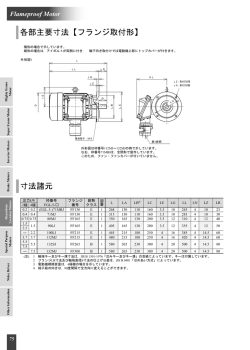
HM-40051-5 取 扱 説 明 書 高効率 ステッピングモーターユニット お買い上げいただきありがとうございます。 この取扱説明書には、製品の取り扱いかたや安全上の注意事項を示して います。 AR シリーズ モーター編 • 取扱説明書をよくお読みになり、製品を安全にお使いください。 • お読みになったあとは、いつでも見られるところに必ず保管してください。 有害物質 はじめに RoHS(EU 指令 お使いになる前に 製品の取り扱いは、電気・機械工学の専門知識を持つ有資格者が 行なってください。お使いになる前に、「安全上のご注意」をよくお 読みのうえ、正しくお使いください。 この製品は、一般的な産業機器の機器組み込み用として設計・製 造されています。その他の用途には使用しないでください。この警 告を無視した結果生じた損害の補償については、当社は一切その 責任を負いませんので、あらかじめご了承ください。 2002/95/EC 27Jan.2003)適合 製品の確認 次のものがすべて揃っていることを確認してください。不足したり破 損している場合は、お買い求めの支店・営業所までご連絡くださ い。 • モーター ........................ 1 台 • 取扱説明書(本書) ....... 1 部 • 平行キー ....................... 1 個 ギヤードタイプに付属(AR46TH、AR46PL、および AR66TH を 除く) 取扱説明書の構成 AR シリーズに関する取扱説明書には、次のものがあります。 よくお読みになってからお使いください。 AR シリーズ モーター編 取扱説明書(本書) モーターの名称と機能や、設置方法について説明しています。 AR シリーズ AC 電源入力ドライバ編 取扱説明書 AR シリーズ DC 電源入力ドライバ編 取扱説明書 • バリスタ .......................... 1 個 DC 電源入力ドライバと組み合わせる電磁ブレーキ付モーターに 付属 各部の名称と機能 図は ARM66MC です。 䊝䊷䉺䊷 ドライバの名称と機能、モーターとドライバの組み合わせ、設置方 法、および接続方法について説明しています。 ⼔ធ┵ሶ䋨M4䋩 ขઃⓣ䋨4䈎ᚲ䋩 規格・CE マーキング AC 電源入力ドライバと組み合わせるモーターは、UL 規格、CSA 規格の認定を取得し、EN 規格にもとづいて CE マーキング(低電圧 㔚⏛䊑䊧䊷䉨 ജゲ 指令)を実施しています。 EN 規格については、TÜV ラインランドの認定を取得しています。 䉦䊒䊤䉦䊋䊷 • 適用規格 適用規格 䊝䊷䉺䊷䉬䊷䊑䊦 䉟䊮䊨䊷 認定機関 規格ファイル No. UL E64199 TÜV R 50124201 UL 1004 㔚⏛䊑䊧䊷䉨䉬䊷䊑䊦 䉦䊒䊤䉦䊋䊷 UL 2111 CSA C22.2 No.100 CSA C22.2 No.77 EN 60034-1 EN 60034-5 規格対応品 • 設置条件(EN 規格) 機器組み込み 過電圧カテゴリー:Ⅱ 汚損度:3(両軸タイプは 2) 感電保護:クラスⅠ • 低電圧指令 この製品は機器組み込み型です。 モーターの保護接地端子は確実に接地してください。 1 運 搬 安全上のご注意 ここに示した注意事項は、製品を安全に正しくお使いいただき、お 客様や他の人々への危害や損傷を未然に防止するためのもので す。内容をよく理解してから製品をお使いください。 • モーター出力軸やモーターケーブルを持たないでください。けが の原因になります。 設 置 • モーターの回転部(出力軸)にカバーを設けてください。けがの 原因になります。 ⼊๔ この警告事項に反した取り扱いをすると、死亡または重傷を負う場 • 通風を妨げる障害物をモーターの周囲に置かないでください。 装置破損の原因になります。 合がある内容を示しています。 運 転 全 般 • 運転中は回転部(出力軸)に触れないでください。けがの原因に • 爆発性雰囲気、引火性ガスの雰囲気、腐食性の雰囲気、水のか かる場所、可燃物のそばでは使用しないでください。火災・感電・ なります。 • 装置の故障や動作の異常が発生したときは、装置全体が安全な 方向へはたらくよう非常停止装置、または非常停止回路を外部 けがの原因になります。 • 設置、接続、運転・操作、点検・故障診断の作業は、適切な資格 を有する人が行なってください。火災・感電・けが、装置破損の原 に設置してください。けがの原因になります。 • モーターは、正常な運転状態でも表面温度が 70 °C を超えることがあります。運転中のモーターに 因になります。 • 通電状態で移動、設置、接続、点検の作業をしないでください。 電源を切ってから作業してください。感電の原因になります。 • 昇降装置に使用するときは、可動部の位置保持対策を行なって ください。電源 OFF 時、モーターは保持力がなくなるため、可動 部が落下して、けが・装置破損の原因になります。 • 電磁ブレーキ付モーターのブレーキ機構は、可動部とモーター の位置保持用です。制動・安全ブレーキとして使用しないでくだ さい。けが・装置破損の原因になります。 設 置 接近できるときは、図の警告ラベルをはっきり見える 位置に貼ってください。やけどの原因になります。 警告ラベル • 電磁ブレーキ用の直流電源は、一次側と強化絶縁された電源を 使用してください。感電の原因になります。 保守・点検 • 絶縁抵抗測定、絶縁耐圧試験を行なうときは、端子に触れない でください。感電の原因になります。 廃 棄 • モーターを廃棄するときは、できるだけ分解し、産業廃棄物として • モーターはクラスⅠ機器に設置してください。感電の原因になり 処理してください。 ます。(ドライバの電源が DC24 V のときは必要ありません。) • 設置するときは、手がモーターに触れないようにするか、接地し 使用上のお願い てください。感電の原因になります。 接 続 • AR シリーズ ドライバ編 取扱説明書に記載されているモーター の接続方法にもとづき、確実に接続してください。火災・感電の 原因になります。 • 接続ケーブルを無理に曲げたり、引っ張ったり、挟み込まないで ください。火災・感電の原因になります。 • 絶縁抵抗測定、絶縁耐圧試験は、モーターとドライバそれぞ れで行なってください モーターとドライバを接続した状態で、絶縁抵抗測定、絶縁耐圧試 験を行なうと、製品が破損するおそれがあります。 • オーバーハング荷重・スラスト荷重は許容値以下で使用して ください 許容値を超えたオーバーハング荷重やスラスト荷重が加わった状 修理・分解・改造 • モーターを分解・改造しないでください。感電・けがの原因になり ます。内部の点検や修理は、お買い上げになった支店または営 業所に連絡してください。 態で運転を続けると、モーターの軸受け(ボールベアリング)が破損 する原因になります。必ず許容値内のオーバーハング荷重・スラス ト荷重で運転してください。詳しくは4ページをご覧ください。 • モーターは、表面温度 100 °C 以下を目安に使用してくださ い ᵈᗧ ドライバには過熱から保護する機能がありますが、モーター自体に この注意事項に反した取り扱いをすると、傷害を負うまたは物的損 はそのような機能がありません。使用周囲温度、運転速度、運転 害が発生する場合がある内容を示しています。 デューティなどの運転条件によっては、モーターケースの表面温度 全 般 • モーターの仕様値を超えて使用しないでください。感電・けが・装 置破損の原因になります。 • 運転中や停止後しばらくの間はモーターに触れないでください。 モーターの表面が高温のため、やけどの原因になります。 が 100 °C を超える場合があります。モーターの軸受け(ボールベア リング)の寿命劣化を抑えるため、モーターケースの表面温度は 100 °C 以下を目安に使用してください。 ハーモニックギヤードタイプは、ギヤ部のグリース劣化を防ぐため、 ギヤ部のケース温度は 70 °C 以下で使用してください。 なお、モーターを連続運転するときは、放熱板(材質:アルミニウム、 250×250×6 mm)と同程度の放熱能力を持つ場所に設置してくださ い。 2 • 励磁最大静止トルク 励磁最大静止トルクは、定格電流でモーターを励磁したときの値で す。専用のドライバと組み合わせたときは、モーター停止時の温度 上昇を抑える機能(カレントダウン機能)によって、励磁最大静止ト 設置方向 モーターの設置方向に制限はありません。 設置方法 ルクも約 50%に低下します。そのため、モーターの起動時は、励磁 放熱性や振動防止を考慮し、できるだけ強固な金属面へ確実に取 最大静止トルクでの加速や運転は可能ですが、停止後は保持トル り付けてください。 クが約 50%に低下します。モーターを選定するときは、静止時の保 持トルクが約 50%に低下することを考慮してください。 設置方法 A 設置方法 B 䉟䊮䊨䊷ฃ䈔 䉟䊮䊨䊷ฃ䈔 • 電磁ブレーキを制動・安全ブレーキとして使用しないでくだ さい 電磁ブレーキをモーターの制動停止に使用しないでください。電磁 ブレーキのブレーキハブが著しく磨耗して、制動力が低下します。 電磁ブレーキは無励磁作動型のため、停電時などに負荷を保持す ㊄ዻ᧼ るのに役立ちますが、負荷を確実に保持する機構ではありません。 ㊄ዻ᧼ 安全ブレーキとして使用しないでください。電磁ブレーキで負荷を 保持するときは、モーターの停止後に行なってください。 種 類 • 両軸タイプのモーター モーター出力軸の反対側の出力軸に、負荷トルク、オーバーハン 取付角 ボルトの 締付トルク 有効ねじ 設置 寸法(mm) 呼び (N·m) 深さ(mm) 方法 標 準 グ荷重、およびスラスト荷重を加えないでください。 • ノイズ対策 • ギヤードタイプの最大トルク A − B 85 M6 3 − B M4 2 8 A 4 15 A PL、PN、PS、 42 M4 2 8 A ハーモニック 60 M5 2.5 10 A 90 M8 4 15 A 90 M8 4 − B ∗1 ギヤード ハーモニック ギヤード ります。グリース漏れによる周囲環境の汚染が問題になるときは、定 4.5 2 M8 最大トルクを超えた負荷が加わると、ギヤが破損します。 ギヤードモーターからまれに、少量のグリースがにじみ出ることがあ 1 M4 90 ギヤードタイプは、必ず最大トルク以下の負荷で運転してください。 • ギヤードモーターのグリース M3 60 42、60 TH ギヤード ノイズ対策については、AR シリーズ ドライバ編 取扱説明書をご覧 ください。 42 ∗2 ∗1 ARM46、ARM66 タイプのみ。 ∗2 ARM98 タイプのみ。 負荷の取り付け 期点検時にグリースのにじみを確認してください。または油受けな 負荷をモーターに取り付けるときは、負荷の軸中心線とモーター出 どの損害防止装置を取り付けてください。油漏れによって、お客様 力軸を揃えてください。カップリングやプーリーをモーター出力軸に の装置や製品などに不具合を発生させる原因になります。 取り付けるときは、出力軸や軸受け(ボールベアリング)に損傷を与 えないでください。 設 置 設置場所 • 電磁ブレーキ付モーターの場合 電磁ブレーキを解放して負荷を取り付けるときは、電磁ブレーキ用 の直流電源が必要です。電磁ブレーキ用ケーブルを使用して、 モーターは機器組み込み用に設計・製造されています。 DC24 V±5%の直流電源をモーターに接続してください。 風通しがよく、点検が容易な次のような場所に設置してください。 ユニットでご購入の場合、電磁ブレーキ用ケーブルは製品に付属 • 屋内に設置された筐体内(換気口を設けてください) しています。 • 使用周囲温度:−10~+50 °C(凍結しないこと) ハーモニックギヤードタイプは 0~+40 °C(凍結しないこと) 㔚⏛䊑䊧䊷䉨↪⋥ᵹ㔚Ḯ 㔚⏛䊑䊧䊷䉨ઃ䊝䊷䉺䊷 • 使用周囲湿度:85%以下(結露しないこと) • 爆発性雰囲気、有害なガス(硫化ガスなど)、および液体のないと DC24 V±5%*1 0.1 Aએ䋨ARM46䋩 0.3 Aએ䋨ARM66䇮69䇮98䋩 㤥 ころ 䊋䊥䉴䉺*2 • 直射日光が当たらないところ ⊕ 䉴䉟䉾䉼 • 塵埃や鉄粉などの少ないところ 㔚⏛䊑䊧䊷䉨↪䉬䊷䊑䊦 • 水(雨や水滴)、油(油滴)、およびその他の液体がかからないと ころ • 塩分の少ないところ • 連続的な振動や過度の衝撃が加わらないところ • 電磁ノイズ(溶接機、動力機器など)が少ないところ • 放射性物質や磁場がなく、真空でないところ ∗1 モーターとドライバ間を 20 m 以上延長するときは、DC24 V±4%の電源 を使用してください。 ∗2 スイッチの接点保護やノイズを防止するため、バリスタをご用意ください [推奨バリスタ:Z15D121(石塚電子株式会社)]。DC 電源入力ドライバ の場合は、モーターに付属しています。 3 • フランジ面に取り付けるとき (ハーモニックギヤードタイプ) • PL ギヤードタイプ、PS ギヤードタイプ ユニット ハーモニックギヤードタイプ(AR98-H を除く)は、フランジ面にあ 品名 減速比 許容オーバーハング荷重(N) 許容 モーター出力軸先端からの距離(mm) スラスト 0 5 10 15 20 200 220 250 280 320 250 270 300 340 390 る負荷取付用のねじ穴を使用して、負荷を直接ギヤに取り付けるこ 5 とができます。 ⽶⩄ 10 AR66 䈰䈛 䊐䊤䊮䉳㕙 7.2 ⽶⩄ขઃ↪䈱 䈰䈛ⓣ 100 25 36 荷重(N) 330 360 400 450 520 480 540 600 680 790 850 940 1050 1190 1380 50 5 ㊄ዻ᧼ 7.2 ねじの ねじの 締付トルク 有効ねじ深さ 呼び 本数 (N·m) (mm) AR46-H M3 6 1.4 5 36 930 1030 1150 1310 1520 AR66-H M4 6 2.5 6 50 1050 1160 1300 1480 1710 ユニット品名 重要 • 負荷をフランジ面に取り付ける場合、出力軸のキーみぞを 併用して負荷を固定することはできません。 • モーターを取り付けている金属板やねじと、負荷が干渉し ないように設計してください。 許容オーバーハング荷重と許容スラスト荷重 重要 両軸タイプのときは、モーター出力軸の反対側の出力軸に、 負荷トルク、オーバーハング荷重、およびスラスト荷重を加 えないでください。 10 AR98 25 • PN ギヤードタイプ ユニット 品名 減速比 品名 AR46 AR46 AR46M AR69 250 270 300 340 390 330 360 400 450 520 480 520 550 580 620 480 540 600 680 790 25 850 940 1050 1110 1190 36 930 1030 1150 1220 1300 50 1050 1160 1300 1380 1490 10 35 44 58 85 − 100 130 180 10 AR98 6.1 270 11.8 ユニット 18 290 340 390 480 品名 24 29 • TH ギヤードタイプ 許容オーバーハング荷重(N) 許容 モーター出力軸先端からの距離(mm) 300 • ハーモニックギヤードタイプ 13.7 16.7 260 100 25 8.8 90 荷重(N) 50 4.6 AR911 品名 − 320 7.2 AR98 ユニット 190 280 荷重(N) AR69M AR98M 150 250 5 AR66 AR66M 120 許容 20 20 220 スラスト 15 15 100 許容オーバーハング荷重(N) 10 10 200 7.2 AR66 5 5 モーター出力軸先端からの距離(mm) 5 許容 スラスト − 36 0 許容オーバーハング荷重(N) モーター出力軸先端からの距離(mm) 0 • 標準タイプ ユニット 300 許容オーバーハング荷重(N) 許容 モーター出力軸先端からの距離(mm) スラスト 0 5 10 15 20 荷重(N) AR46 180 220 270 360 510 220 AR66 320 370 440 550 720 450 AR98 1090 1150 1230 1310 1410 1300 スラスト • ハーモニックギヤードタイプの許容モーメント荷重 アームやテーブルをフランジ面に取り付けるときに、偏心荷重が加 0 5 10 15 20 荷重(N) AR46 10 14 20 30 − 15 わる場合は、次の計算式でモーメント荷重を算出してください。 AR66 70 80 100 120 150 40 モーメント荷重は、表の許容値を超えないでください。 AR98 220 250 300 350 400 100 モーメント荷重:M(N·m) = F × L • PL ギヤードタイプ、PS ギヤードタイプ ユニット 品名 許容オーバーハング荷重(N) 減速比 許容 モーター出力軸先端からの距離(mm) 0 5 10 15 20 73 84 100 123 − AR46 10 36 50 4 109 127 150 184 − (N·m) スラスト AR46-H 5.6 AR66-H 11.6 50 25 許容モーメント荷重 荷重(N) 5 7.2 ユニット品名 F L 接 続 点 検 モーターの運転後は、定期的に次の項目について点検することを ドライバとの接続 おすすめします。異常があるときは使用を中止し、お客様ご相談セ 接続方法は、AR シリーズ ドライバ編 取扱説明書をご覧ください。 ケーブル同士を接続したコネクタはカプラカバーで覆ってください。 モーターコネクタピン配列 • ドライバ:AC 電源入力 ピン No. 点検項目 • モーターの取付ねじに緩みがないか。 線 色 • モーターの軸受け(ボールベアリング)などから異常な音が発生 線 径 2 1 白 AWG26(0.14 mm ) 2 紫 AWG26(0.14 mm ) 3 赤 AWG22(0.3 mm ) 4 青 AWG22(0.3 mm ) 5 緑 AWG22(0.3 mm ) 6 黒 AWG26(0.14 mm ) 7 茶 AWG26(0.14 mm ) 8 灰 AWG22(0.3 mm ) 9 橙 AWG22(0.3 mm ) 10 − − ピン No. 線 色 線 径 1 白 AWG26(0.14 mm ) 2 黒 AWG26(0.14 mm ) 3 紫 AWG26(0.14 mm ) 4 茶 AWG26(0.14 mm ) 6 7 8 9 10 1 2 3 4 5 ンターにお問い合わせください。 2 2 2 してないか。 • モーター出力軸と負荷軸に心ズレがないか。 • モーターケーブルに傷、ストレスや、ドライバとの接続部に緩みが ないか。 2 2 2 2 一般仕様 ∗ IP54 (両軸タイプは IP20) 保護等級 2 −10~+50 °C(凍結しないこと) 周囲温度 ハーモニックギヤードタイプは 0~+40 °C(凍結しないこと) • ドライバ:DC 電源入力 6 7 8 9 10 1 2 3 4 5 使用環境 2 2 AWG22(0.3 mm ) 赤 AWG22(0.3 mm ) 7 灰 AWG22(0.3 mm ) 10 橙 周囲温度 2 緑 9 海抜 1000 m 以下 雰囲気 2 6 青 85%以下(結露しないこと) 高 度 2 5 8 湿 度 2 保存環境 85%以下(結露しないこと) 海抜 3000 m 以下 周囲温度 2 AWG22(0.3 mm ) − − 輸送環境 モーターの接地 モーターの保護接地端子を確実に接地してください。(ドライバの 電源が DC24 V のときは必要ありません。) −20~+60 °C(凍結しないこと) 高 度 雰囲気 AWG22(0.3 mm ) 水、油がかからないこと。 湿 度 2 2 腐食性ガス、塵埃がないこと。 腐食性ガス、塵埃がないこと。 水、油がかからないこと。 −20~+60 °C(凍結しないこと) 湿 度 85%以下(結露しないこと) 高 度 海抜 3000 m 以下 雰囲気 腐食性ガス、塵埃がないこと。 水、油がかからないこと。 ∗ 取付面とコネクタ部を除く。 締付トルク:1.2 N·m 接地線は AWG18(0.75 mm2)以上のものを使用してください。 接地するときは丸型端子を使用し、座金を入れたボルトで固定して ください。接地線や圧着端子は付属していません。 PE 5 オプション(別売) • 接続ケーブルセット、可動接続ケーブルセット モーターとドライバを接続するときに必要なケーブルです。 電磁ブレーキ付モーター用は、モーター用と電磁ブレーキ用の 2 本組です。 • 接続ケーブルセット • 接続ケーブルセット 標準モーター用 ∗ 電磁ブレーキ付モーター用 ∗ 品 名 長さ(m) 品 名 長さ(m) CC010VAF(2) 1 CC010VAFB(2) 1 CC020VAF(2) 2 CC020VAFB(2) 2 CC030VAF(2) 3 CC030VAFB(2) 3 CC050VAF(2) 5 CC050VAFB(2) 5 CC070VAF(2) 7 CC070VAFB(2) 7 CC100VAF(2) 10 CC100VAFB(2) 10 CC150VAF(2) 15 CC150VAFB(2) 15 CC200VAF(2) 20 CC200VAFB(2) 20 CC300VAF(2) 30 CC300VAFB(2) 30 • 可動接続ケーブルセット • 可動接続ケーブルセット 標準モーター用 ∗ 電磁ブレーキ付モーター用 ∗ 品 名 長さ(m) 品 名 長さ(m) CC010VAR(2) 1 CC010VARB(2) 1 CC020VAR(2) 2 CC020VARB(2) 2 CC030VAR(2) 3 CC030VARB(2) 3 CC050VAR(2) 5 CC050VARB(2) 5 CC070VAR(2) 7 CC070VARB(2) 7 CC100VAR(2) 10 CC100VARB(2) 10 CC150VAR(2) 15 CC150VARB(2) 15 CC200VAR(2) 20 CC200VARB(2) 20 CC300VAR(2) 30 CC300VARB(2) 30 ∗ DC 電源入力ドライバの場合は、品名に 2 が入ります。 • MCS カップリング アルミ合金製のハブと樹脂製のスパイダーによる、3 ピース構造の カップリングです。スパイダーの適度な弾性がモーターの振動を抑 制します。 • この取扱説明書の一部または全部を無断で転載、複製するこ とは、禁止されています。 • 取扱説明書に記載されている情報、回路、機器、および装置 の利用に関して産業財産権上の問題が生じても、当社は一切 • モーター取付金具 標準タイプのモーターを固定する金具です。 の責任を負いません。 • 製品の性能、仕様および外観は改良のため予告なく変更する ことがありますのでご了承ください。 • 取扱説明書には正確な情報を記載するよう努めていますが、 万一ご不審な点や誤り、記載もれなどにお気づきの点がありま したら、最寄りのお客様ご相談センターまでご連絡ください。 • と は、日本その他の国における オリエンタルモーター株式会社の登録商標または商標です。 © Copyright ORIENTAL MOTOR CO., LTD. 2009 http://www.orientalmotor.co.jp/ 䃂㩷ຠ䈮䈧䈇䈩䈱䈗⾰䇮䈗⋧⺣䈲䈍ቴ᭽䈗⋧⺣䉶䊮䉺䊷䈻䈍䈇ว䉒䈞䈒䈣䈘䈇䇯 㩷 䊐䊥䊷䉮䊷䊦䋨ήᢱ䋩䈪䈜䇯៤Ꮺ㔚䊶PHS䈎䉌䉅䈗↪䈏น⢻䈪䈜䇯 㩷 ฃઃᤨ㑆㩷 ᐔᣣ㩷 㩷 㩷 ᦐᣣ㩷 9:00䌾18:30 9:00䌾17:30 ᧲㩷 ੩㩷 TEL 0120-925-410 ฬฎደ㩷 TEL 0120-925-420 ᄢ㩷 㒋㩷 TEL 0120-925-430 FAX 0120-925-601 FAX 0120-925-602 FAX 0120-925-603 䈖䈱ขᛒ⺑ᦠ䈲ౣ↢⚕䉕↪䈚䈩䈇䉁䈜䇯 6 HM-40051-5 OPERATING MANUAL High-efficiency closed loop stepping motor unit Thank you for purchasing an Oriental Motor product. This Operating Manual describes product handling procedures and safety precautions. • Please read it thoroughly to ensure safe operation. AR Series Motor • Always keep the manual where it is readily available. Hazardous substances Introduction RoHS (Directive Before use Only qualified personnel should work with the product. Use the product correctly after thoroughly reading the section “Safety precautions.” The product described in this manual has been designed and manufactured for use in general industrial machinery, and must not be used for any other purpose. Oriental Motor Co., Ltd. is not responsible for any damage caused through failure to observe this warning. Structure of the manual The AR series comes with the manuals specified below. Read the manuals carefully before using your AR series unit. AR Series Motor OPERATING MANUAL (this document) This manual explains the names and functions of motor components as well as the installation method. AR Series AC power supply input Driver OPERATING MANUAL AR Series DC power supply input Driver OPERATING MANUAL These manuals explain the names and functions of driver components, motor/driver combinations, installation method, and connection method. Standards and CE Marking All motors combined with a driver of AC power input type are recognized by UL and certified by CSA, and bear the CE marking (Low Voltage Directive) in compliance with the EN Standards. A certification by TÜV Rheinland has been obtained to confirm compliance with the EN standards. 2002/95/EC 27Jan.2003) compliant Checking the product Verify that the items listed below are included. Report any missing or damaged items to the branch or sales office from which you purchased the product. • Motor............................................................ 1 unit • OPERATING MANUAL (this document) ... 1 copy • Parallel key ................................................... 1 pc. Supplied with geared types (except for the AR46TH, AR46PL and AR66TH). • Varistor......................................................... 1 pc. Supplied with electromagnetic brake motors combined with a driver of DC power input type. Names and functions of parts This figure shows the ARM66MC. Motor Protective earth terminal (M4) Mounting holes (4 locations) Output shaft Electromagnetic brake Pilot Motor cable Connector cover Electromagnetic brake cable Connector cover • Applicable Standards Applicable Standards UL 1004 UL 2111 CSA C22.2 No.100 CSA C22.2 No.77 EN 60034-1 EN 60034-5 Certification Body Standards File No. UL E64199 TÜV R 50124201 Conforming to the respective standards. • Installation conditions (EN Standard) Motor is to be used as a component within other equipment. Overvoltage category: II Pollution degree: 3 (or 2 in case of double shaft type) Protection against electric shock: Class I • For Low Voltage Directive The product is a type with machinery incorporated, so it should be installed within an enclosure. Securely ground the Protective Earth Terminals of the motor. 1 Safety precautions The precautions described below are intended to prevent danger or injury to the user and other personnel through safe, correct use of the product. Fully understand the meaning of each item before using the product. • Do not touch the motor during operation or immediately after stopping. The surface is hot and may cause a skin burn(s). Transportation • Do not hold the motor output shaft or motor cable. This may cause injury. Installation Warning Handling the product without observing the instructions that accompany a “Warning” symbol may result in serious injury or death. General • Do not use the product in explosive or corrosive environments, in the presence of flammable gases, locations subjected to splashing water, or near combustibles. Doing so may result in fire, electric shock or injury. • Assign qualified personnel the task of installing, wiring, operating/controlling, inspecting and troubleshooting the product. Failure to do so may result in fire, electric shock, injury or damage to equipment. • Do not transport, install the product, perform connections or inspections when the power is on. Always turn the power off before carrying out these operations. Failure to do so may result in electric shock. • Provide a means to hold the moving parts in place for applications involving vertical travel. The motor loses holding torque when the power is shut off, allowing the moving parts to fall and possibly cause injury or damage to equipment. • The brake mechanism of an electromagnetic brake motor is used to keep the moving part and motor in position. Do not use it as a deceleration/safety brake. Doing so may result in injury or damage to the equipment. Installation • To prevent the risk of electric shock, use the motor for class I equipment only. (Not required when the driver’s power supply specification is 24 VDC.) • Install the motor so as to avoid contact with hands, or ground them to prevent the risk of electric shock. Connection • Connect the motor securely according to the motor connection method explained in the AR Series Driver OPERATING MANUAL. Failure to do so may result in fire or electric shock. • Do not forcibly bend, pull or pinch the cables. Doing so may result in fire or electric shock. Repair, disassembly and modification • Do not disassemble or modify the motor. This may cause electric shock or injury. Refer all such internal inspections and repairs to the branch or sales office from which you purchased the product. Caution Handling the product without observing the instructions that accompany a “Caution” symbol may result in injury or property damage. General • Do not use the motor beyond its specifications, or electric shock, injury or damage to equipment may result. 2 • Provide a cover over the rotating parts (output shaft) of the motor to prevent injury. • To prevent the risk of damage to equipment, leave nothing around the motor that would obstruct ventilation. Operation • Do not touch the rotating parts (output shaft) of the motor during operation. This may cause injury. • Provide an emergency stop device or emergency stop circuit external to the equipment so that the entire equipment will operate safely in the event of a system failure or malfunction. Failure to do so may result in injury. • The motor’s surface temperature may exceed 70 °C (158 °F), even under normal operating conditions. If Warning a motor is accessible during operation, post a label warning label shown in the figure in a conspicuous position to prevent the risk of skin burn(s). • For the power supply input to the electromagnetic brake, use a DC power supply with reinforced insulation on the primary side. Maintenance and inspection • To prevent the risk of electric shock, do not touch the terminals while measuring the insulation resistance or conducting a voltage-resistance test. Disposal • To dispose of the motor, disassemble it into parts and components as much as possible and dispose of individual parts/components as industrial waste. Precautions for use • Conduct the insulation resistance measurement or withstand voltage test separately on the motor and the driver. Conducting the insulation resistance measurement or withstand voltage test with the motor and driver connected may result in injury or damage to equipment. • Do not apply an overhung load and thrust load in excess of the specified permissible limit. Operating the motor under an excessive overhung load and thrust load may damage the motor bearings (ball bearings). Be sure to operate the motor within the specified permissible limit of overhung load and thrust load. See page 4 for details. • Use the motor in conditions where its surface temperature will not exceed 100 °C (212 °F). The driver has an overheat-protection function, but the motor has no such feature. The motor case’s surface temperature may exceed 100 °C (212 °F) under certain conditions (ambient temperature, operating speed, duty cycle, etc.). To prevent the motor bearings (ball bearings) from reaching its usable life quickly, use the motor in conditions where its surface temperature will not exceed 100 °C (212 °F). Use the harmonic geared type motor in a condition where the gear case temperature does not exceed 70 °C (158 °F), in order to prevent deterioration of grease in the gear. If the motor is to be operated continuously, install the motor in a location where heat dissipation capacity equivalent to a level achieved with a heat sink [made of aluminum, 250×250×6 mm (9.84×9.84×0.24 in.)] is ensured. • Maximum static torque at excitation Maximum static torque at excitation represents a value obtained when the motor is excited using a rated current. When combined with a dedicated driver and while the motor is stopped motor temperature increases are suppressed due to a current reduction of approximately 50% by the current cutback function. Acceleration and operation at the maximum static torque at excitation is possible in start-up, but it has approximately 50% holding power after it has stopped. When selecting a motor for your application, consider the fact that the holding power will be reduced to approximately 50% after the motor has stopped. • Do not use the electromagnetic brake to reduce speed or as a safety brake. Do not use the electromagnetic brake as a means to decelerate and stop the motor. The brake hub of the electromagnetic brake will wear significantly and the braking force will drop. The electromagnetic brake is of power-off activated type. This means that although it helps maintain the position of the load in the event of power outage, etc., this brake cannot securely hold the load in place. Accordingly, do not use the electromagnetic brake as a safety brake. To use the electromagnetic brake to hold the load in place, do so after the motor has stopped. • Double shaft motor Do not apply load torque, overhung load or thrust load to the output shaft on the opposite side of the motor output shaft. • Preventing electrical noise See AR Series Driver OPERATING MANUAL for measures with regard to noise. • Maximum torque of geared type motor Always operate the geared type motor under a load not exceeding the maximum torque. If the load exceeds the maximum torque, the gear will be damaged. • About grease of geared motor On rare occasions, a small amount of grease may ooze out from the geared motor. If there is concern over possible environmental damage resulting from the leakage of grease, check for grease stains during regular inspections. Alternatively, install an oil pan or other device to prevent leakage from causing further damage. Oil leakage may lead to problems in the customer’s equipment or products. Installation Location for installation The motor is designed and manufactured for installation in equipment. Install it in a well-ventilated location that provides easy access for inspection. The location must also satisfy the following conditions: • Inside an enclosure that is installed indoors (provide vent holes) • Operating ambient temperature −10 to +50 °C (+14 to +122 °F) (non-freezing) Harmonic geard type: 0 to +40 °C (+32 to +104 °F) (non-freezing) • Operating ambient humidity 85% or less (non-condensing) • Area that is free of explosive atmosphere or toxic gas (such as sulfuric gas) or liquid • Area not exposed to direct sun • Area free of excessive amount of dust, iron particles or the like • Area not subject to splashing water (rain, water droplets), oil (oil droplets) or other liquids • Area free of excessive salt • Area not subject to continuous vibration or excessive shocks • Area free of excessive electromagnetic noise (from welders, power machinery, etc.) • Area free of radioactive materials, magnetic fields or vacuum Installation direction The motor can be installed in any direction. Installation method To allow for heat dissipation and prevent vibration, install the motor on a metal surface of sufficient strength. Installation method A Installation method B Through hole for pilot Through hole for pilot Metal plate Metal plate • Standard type Frame size [mm (in.)] Bolt size Tightening torque [N·m (oz-in)] Effective depth of bolt [mm (in.)] Installation method 4.5 (0.177) A − B Installation method 42 (1.65) M3 1 (142) 60 (2.36) M4 2 (280) 85 (3.35) M6 3 (420) • TH geared type Frame size [mm (in.)] Bolt size Tightening torque [N·m (oz-in)] Effective depth of bolt [mm (in.)] 42 (1.65) 60 (2.36) M4 2 (280) 8 (0.315) 90 (3.54) M8 4 (560) 15 (0.591) A • PL geared, PN geared, PS geared, harmonic geared type (only ARM46, ARM66 type) Tightening torque [N·m (oz-in)] Effective depth of bolt [mm (in.)] Frame size [mm (in.)] Bolt size 42 (1.65) M4 2 (280) 8 (0.315) 60 (2.36) M5 2.5 (350) 10 (0.394) 90 (3.54) M8 4 (560) 15 (0.591) Installation method A • Harmonic geared type (only ARM98 type) Frame size [mm (in.)] Bolt size Tightening torque [N·m (oz-in)] Effective depth of bolt [mm (in.)] Installation method 90 (3.54) M8 4 (560) − B 3 Installing a load When connecting a load to the motor, align the centers of the motor’s output shaft and load shaft. Be careful not to damage the output shaft or the bearings (ball bearings) when installing a coupling or pulley to the motor’s output shaft. • Electromagnetic brake motor DC power supply for electromagnetic brake Black Varistor∗2 Permissible overhung load [N (lb.)] Unit model AR46 AR46M AR66M 0.1 A or more (ARM46) 0.3 A or more (ARM66, 69, 98) AR69 AR98 Switch AR98M AR911 ∗1 If the distance between the motor and driver is extended to 20 m (65.6 ft.) or longer, use a power supply of 24 VDC±4%. ∗2 To protect the switch contacts and prevent generation of noise, it is recommended that a varistor be used. [recommended varistor: Z15D121 (Ishizuka Electronics Corporation)]. If the driver is of DC power supply input, an electromagnetic brake cable is supplied with the motor. • Installing on the flange surface (harmonic geared type) With a harmonic geared type (excluding AR98-H ), a load can be installed directly to the gear using the load mounting holes provided on the flange surface. 5 (0.2) 10 15 20 (0.39) (0.59) (0.79) 35 (7.8) 44 (9.9) 58 (13) 85 (19.1) − 90 (20) 100 (22) 130 (29) 180 (40) 270 (60) Effective depth of bolt [mm (in.)] Bolt size Number of bolts Tightening torque [N·m (oz-in)] AR46-H M3 6 1.4 (198) 5 (0.2) AR66-H M4 6 2.5 (350) 6 (0.24) • When installing a load on the flange surface, the load cannot be affixed using the key groove in the output shaft. • Design an appropriate installation layout so that the load will not contact the metal plate or bolts used for installing the motor. 4.6 (1.03) 6.1 (1.37) 8.8 (1.98) 11.8 (2.6) 13.7 (3) 16.7 (3.7) 260 (58) 290 (65) 340 (76) 390 (87) 480 (108) 18 (4) 24 (5.4) 29 (6.5) Permissible overhung load [N (lb.)] Unit model Distance from the tip of motor’s output shaft [mm (in.)] Permissible thrust load [N (lb.)] 0 (0) 5 (0.2) 10 15 20 (0.39) (0.59) (0.79) AR46 10 (2.2) 14 (3.1) 20 (4.5) 30 (6.7) − 15 (3.3) AR66 70 (15.7) 80 (18) 100 (22) 120 (27) 150 (33) 40 (9) AR98 220 (49) 250 (56) 300 (67) 350 (78) 400 (90) 100 (22) • PL geared type, PS geared type Permissible overhung load [N (lb.)] Unit model Bolts Permissible thrust load [N (lb.)] • TH geared type Metal plate AR46 AR66 AR98 4 0 (0) Load mounting holes Load Note Distance from the tip of motor’s output shaft [mm (in.)] AR69M White Electromagnetic brake cable Unit model With a double shaft type, do not apply load torque, overhung load or thrust load to the output shaft on the opposite side of the motor output shaft. AR66 24 VDC±5%∗1 Frange Note • Standard type To release the electromagnetic brake and install the load, a DC power supply is needed to power the electromagnetic brake. Use an electromagnetic brake cable to connect a DC power supply of 24 VDC±5% to the motor. If you purchased a unit model, the product comes with an electromagnetic brake cable. Electromagnetic brake motor Permissible overhung load and permissible thrust load Gear ratio 5 7.2 10 Distance from the tip of motor’s output shaft [mm (in.)] 0 (0) 5 (0.2) 73 84 (16.4) (18.9) 10 15 20 (0.39) (0.59) (0.79) 100 (22) 123 (27) Permissible thrust load [N (lb.)] − 50 (11.2) 25 36 50 109 (24) 127 (28) 150 (33) 184 (41) − 5 200 (45) 220 (49) 250 (56) 280 (63) 320 (72) 7.2 10 250 (56) 270 (60) 300 (67) 340 (76) 390 (87) 25 36 50 330 (74) 360 (81) 400 (90) 450 (101) 520 (117) 5 7.2 10 480 (108) 540 (121) 600 (135) 680 (153) 790 (177) 25 850 (191) 940 (210) 1050 (230) 1190 (260) 1380 (310) 36 930 (200) 1030 (230) 1150 (250) 1310 (290) 1520 (340) 50 1050 (230) 1160 (260) 1300 (290) 1480 (330) 1710 (380) 100 (22) 300 (67) • PN geared type Connection Permissible overhung load [N (lb.)] Unit model Gear ratio 0 (0) 5 (0.2) − 100 (22) 120 (27) 150 (33) 190 (42) − 5 200 (45) 220 (49) 250 (56) 280 (63) 320 (72) 7.2 10 250 (56) 270 (60) 300 (67) 340 (76) 390 (87) AR46 AR66 AR98 Distance from the tip of motor’s output shaft [mm (in.)] 10 15 20 (0.39) (0.59) (0.79) 25 36 50 330 (74) 360 (81) 400 (90) 450 (101) 520 (117) 5 480 (108) 520 (117) 550 (123) 580 (130) 7.2 10 480 (108) 540 (121) 600 (135) 25 850 (191) 940 (210) 36 930 (200) 50 1050 (230) Permissible thrust load [N (lb.)] 100 (22) • Driver: AC power supply input Pin No. Lead color Lead size 2 1 White AWG26 (0.14 mm ) 2 Purple AWG26 (0.14 mm ) 2 2 3 Red AWG22 (0.3 mm ) 4 Blue AWG22 (0.3 mm ) 620 (139) 5 Green AWG22 (0.3 mm ) 6 Black AWG26 (0.14 mm ) 680 (153) 790 (177) 7 Brown AWG26 (0.14 mm ) 8 Gray AWG22 (0.3 mm ) 1050 (230) 1110 (240) 1190 (260) 9 Orange AWG22 (0.3 mm ) 1030 (230) 1150 (250) 1220 (270) 1300 (290) 10 − 1160 (260) 1300 (290) 1380 (310) 1490 (330) 6 7 8 9 10 1 2 3 4 5 300 (67) Distance from the tip of motor’s output shaft [mm (in.)] 10 15 20 (0.39) (0.59) (0.79) Permissible thrust load [N (lb.)] 0 (0) 5 (0.2) AR46 180 (40) 220 (49) 270 (60) 360 (81) 510 (114) 220 (49) AR66 320 (72) 370 (83) 440 (99) 550 (123) 720 (162) 450 (101) AR98 1090 (240) 1150 (250) 1230 (270) 1310 (290) 1410 (310) 1300 (290) • Permissible moment load of the harmonic geared type When installing an arm or table on the flange surface, calculate the moment load using the formula below if the flange surface receives any eccentric load. The moment load should not exceed the permissible value specified in the table. L Moment load: M [N·m (oz-in)] = F × L F Permissible moment load [N·m (oz-in)] AR46-H 5.6 (790) AR66-H 11.6 (1640) • Driver: DC power supply input 6 7 8 9 10 Permissible overhung load [N (lb.)] Unit model Refer to AR Series Driver OPERATING MANUAL for the connection method. After the cables have been interconnected, cover each connector with the connector cover. Motor connector pin assignment • Harmonic geared type Unit model Connecting to the driver 1 2 3 4 5 2 2 2 2 2 2 − Pin No. Lead color Lead size 2 1 White AWG26 (0.14 mm ) 2 Black AWG26 (0.14 mm ) 3 Purple AWG26 (0.14 mm ) 4 Brown AWG26 (0.14 mm ) 2 2 2 2 5 Green AWG22 (0.3 mm ) 6 Red AWG22 (0.3 mm ) 7 Gray AWG22 (0.3 mm ) 8 Blue AWG22 (0.3 mm ) 9 Orange AWG22 (0.3 mm ) 10 − 2 2 2 2 − Grounding the motor Be sure to ground the Protective Earth Terminal of the motor. (Not required when the driver’s power supply specification is 24 VDC.) Tightening torque: 1.2 N·m (170 oz-in) Use a grounding wire larger than AWG18 (0.75 mm2). To ground the motor, use a round terminal and affix it with a bolt over an inner clip washer. The motor does not come with a Protective Earth cable or crimp terminal. PE Inspection It is recommended that periodic inspections be conducted for the items listed below after each operation of the motor. If an abnormal condition is noted, discontinue any use and contact your nearest office. During inspection • Are any of the motor mounting screws loose? • Check for any unusual noises in the motor’s bearings (ball bearings) or other moving parts. • Are the motor’s output shaft and load shaft out of alignment? • Are there any scratches, signs of stress or loose driver connections in the motor cable? 5 • MCS coupling General specifications IP54∗(IP20 for the double shaft type) Degree of protection Operation environment Storage environment Shipping environment Ambient temperature −10 to +50 °C (+14 to +122 °F) (non-freezing) Harmonic geard type: 0 to +40 °C (+32 to +104 °F) (non-freezing) Humidity 85% or less (non-condensing) Altitude Up to 1000 m (3300 ft.) above sea level Surrounding atmosphere No corrosive gas, dust, water or oil Ambient temperature −20 to +60 °C (−4 to +140 °F) (non-freezing) Humidity 85% or less (non-condensing) Altitude Up to 3000 m (10000 ft.) above sea level Surrounding atmosphere No corrosive gas, dust, water or oil Ambient temperature −20 to +60 °C (−4 to +140 °F) (non-freezing) Humidity 85% or less (non-condensing) Altitude Up to 3000 m (10000 ft.) above sea level A 3-piece coupling consisting of an aluminum alloy hub and resin spider. The spider offering an appropriate level of elasticity suppresses motor vibration. • Motor mounting bracket A bracket used to affix the standard motor. Surrounding No corrosive gas, dust, water or oil atmosphere ∗ Excluding the installation surface and connectors. Options (sold separately) • Motor cable A cable is needed to connect the motor and driver. The cable set for electromagnetic brake includes two cables, one for motor and the other for the electromagnetic brake. • Motor cable • Cable set for electromagnetic brake motor Model∗ Length [m (ft.)] Model∗ Length [m (ft.)] CC010VAF(2) 1 (3.3) CC010VAFB(2) 1 (3.3) CC020VAF(2) 2 (6.6) CC020VAFB(2) 2 (6.6) CC030VAF(2) 3 (9.8) CC030VAFB(2) 3 (9.8) CC050VAF(2) 5 (16.4) CC050VAFB(2) 5 (16.4) CC070VAF(2) 7 (23) CC070VAFB(2) 7 (23) CC100VAF(2) 10 (32.8) CC100VAFB(2) 10 (32.8) CC150VAF(2) 15 (49.2) CC150VAFB(2) 15 (49.2) CC200VAF(2) 20 (65.6) CC200VAFB(2) 20 (65.6) CC300VAF(2) 30 (98.4) CC300VAFB(2) 30 (98.4) • Flexible motor cable • Flexible cable set for electromagnetic brake motor Model∗ Length [m (ft.)] Model∗ Length [m (ft.)] CC010VAR(2) 1 (3.3) CC010VARB(2) 1 (3.3) CC020VAR(2) 2 (6.6) CC020VARB(2) 2 (6.6) CC030VAR(2) 3 (9.8) CC030VARB(2) 3 (9.8) CC050VAR(2) 5 (16.4) CC050VARB(2) 5 (16.4) CC070VAR(2) 7 (23) CC070VARB(2) 7 (23) CC100VAR(2) 10 (32.8) CC100VARB(2) CC150VAR(2) 15 (49.2) CC200VAR(2) 20 (65.6) • Unauthorized reproduction or copying of all or part of this manual is prohibited. • Oriental Motor shall not be liable whatsoever for any problems relating to industrial property rights arising from use of any information, circuit, equipment or device provided or referenced in this manual. • Characteristics, specifications and dimensions are subject to change without notice. • While we make every effort to offer accurate information in the manual, we welcome your input. Should you find unclear descriptions, errors or omissions, please contact the nearest office. • and are registered trademarks or trademarks of Oriental Motor Co., Ltd., in Japan and other countries. © Copyright ORIENTAL MOTOR CO., LTD. 2009 • Please contact your nearest Oriental Motor office for further information. Technical Support Tel:(800)468-3982 8:30 A.M. to 5:00 P.M., P.S.T. (M-F) 7:30 A.M. to 5:00 P.M., C.S.T. (M-F) E-mail: [email protected] www.orientalmotor.com Headquarters and Düsseldorf Office Munich Office Hamburg Office Tel:0211-52067-00 Tel:089-3181225-00 Tel:040-76910443 Fax:0211-52067-099 Fax:089-3181225-25 Fax:040-76910445 Tel:01256-347090 Fax:01256-347099 Tel:01 47 86 97 50 Fax:01 47 82 45 16 Tel:02-93906346 Fax:02-93906348 Tel:(02)8228-0707 Fax:(02)8228-0708 10 (32.8) Tel:(6745)7344 Fax:(6745)9405 CC150VARB(2) 15 (49.2) Tel:(03)22875778 Fax:(03)22875528 CC200VARB(2) 20 (65.6) Tel:66-2-254-6113 Fax:66-2-254-6114 KOREA Tel:(032)822-2042~3 Fax:(032)819-8745 CC300VAR(2) 30 (98.4) CC300VARB(2) 30 (98.4) ∗ If the driver is of DC power supply input, the model name contains 2. Headquarters Tokyo, Japan Tel:(03)3835-0684 Fax:(03)3835-1890 Printed on Recycled Paper 6
© Copyright 2026 Paperzz