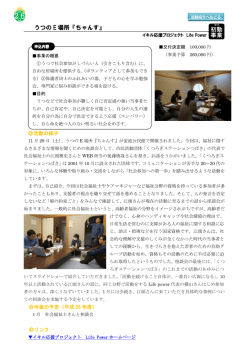
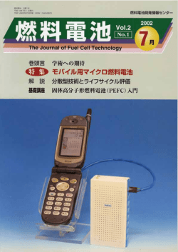
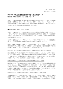
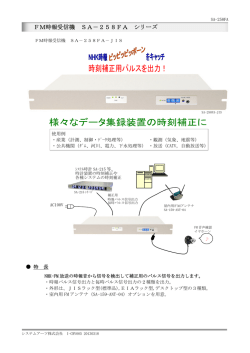
R E D OX F LOW
B AT T E RY
2016.3 版
レドックスフロー電池の特徴
レドックスフロー電池の原理
レドックスフロー電池の原理
PrincipleFeatures
of the Redox
of theFlow
Redox
Battery
Flow Battery
SystemSystem
Principle of the Redox Flow Battery System
原 理
蓄電容量の大型化が容易
Principle
充電残量の正確な把握が可能
Easy to scale up
充電
Charge
発電
放電 Discharge
出力と容量の独立設計が可能
負荷
PCS
正極 Positive
起電力を直接測定可能であるため、
充放電中の充電残量をリアルタイムに把握可能
The output specification and the capacity
specification can be designed independently
Load
交流/直流変換器
Generation
Accurate detection of SOC (state of charge)
The SOC can be measured on a real time basis by
measuring electromotive force directly during operation
セル Negative 負極
Cell
V5+ / V4+
e-
V5+
V2+
e-
電解液タンク
Electrolyte Tank
V2+ / V3+
充電
Charge
電解液タンク
放電
Discharge
Electrolyte Tank
4+
V
H
負荷へ
出力UP
容量UP
To load
Power enhancement
Energy enhancement
i
PCS
V
容量UP
Energy enhancement
3+
V
+
出力(kW)∝セルスタックの台数
Power(kW) ∝ the number of cell stacks
電極
ポンプ
Electrode
蓄 電 容 量(k W h)∝電 解 液の 量
隔膜
Energy(kWh) ∝ the amount of electrolyte
ポンプ
Membrane
Pump
用途に応じた最適な構成を構築可能
負極電解液フロー
電力系統 Power grid
Negative electrolyte
Heat exchanger (cooling)
AC
セルスタック
Cell stack
交直変換装置
PCS
Materials and components are non-flammable
and incombustible
電解液:硫酸バナジウム水溶液
Electrolyte: Vanadium sulphate-water solution
・不燃性
Non-flammable
セルスタック、配管:塩化ビニル
Cell Stacks, Pipes: PVC
単セル構成 Composition of single cell
フレーム
Frame
電極
隔膜
電極
双極板
Electrode Membrane Electrode Bi-polar plate
・難燃性(着火温度:455℃)
Incombustible (ignition point: 455℃)
充放電反応はバナジウムイオンの価数変化のみ
(析出、
溶解を伴わない反応)
であり、
電解液には劣化がなく半永久的に利用可能
The battery reaction principle is simply the change
of valence of the vanadium ions in the electrolyte
(without deposition and dissolution); therefore the
life of electrolyte is not susceptible
正 極
positive
充電 Charge
V4+
V+5 + e -
放電 Discharge
負 極
negative
充電 Charge
V3+ +e-
V2+
放電 Discharge
・空気中では自己消火性
Self-extinguishing in air
ポンプ
Pump
火災の可能性が極めて低い
The possibility of fire is extremely low
01
Long-lived active material
・正負の電解液が混合しても発火しない
Positive electrolyte and negative electrolyte can be
mixed without ignition
DC
電解液タンク
タンク
Tank
活物質が長寿命
Safety
熱交換器 (冷却)
Electrolyte tank
Pump
The SOC management in complex
charge/discharge pattern is easy
安 全
不燃、難燃材料で構成されている
Positive electrolyte
ポンプ
不規則な充放電時の残量管理が容易
The flow battery can be built in the most suitable
constitution depending per use
Composition
正極電解液フロー
V=E - iR
Pump
レドックス(Redox) :活物質の還元(reduction), 酸化(oxidation)
フロー(Flow)
:活物質の溶液を外部タンクに貯蔵しポンプで循環(flow)
Redox: Reduction & Oxidation of active material
Flow: Electrolyte is stored in tanks and flowed by pumps
構 成
V=E
充放電サイクルに対して極めて強い
A long charge/discharge cycle service life is realized
02
レドックスフロー電池の適用ケース
Applications of the Redox Flow Battery System
電力会社
レドックスフロー電池の導入例1
レドックスフロー電池の原理
Principle
Supply
of the
references
Redox Flow
of Redox
Battery
FlowSystem
Battery System
需要家
Utilities and DSOs
設置先
Application
火力発電、水力発電の調整予備力の一部を担い、
余剰電力対応、周波数調整に貢献します
電力の効率的な運用や安定した電力確保等、
蓄電池を用いた様々なサービスを提供します
電 力会社
研究開発
Storage of renewable(wind, solar) surplus power
Various services with the battery including effective
and stable use of the power are suggested
オフィスビル
O f f ice b uildin g
負荷平 準
電 力会社
研 究、実 証
NEDO
風 力 発 電 出 力 平滑 化 検 証(単 基)
建 設 会社
研 究 開 発(太 陽 光とのハイブリッド)
工場
瞬 低補 償、ピークカット
電 力会社
瞬 低補 償、ピークカット
大学
負荷平 準 化、ピークカット
研究 所
負荷平 準 化
電 力会社
研究開発
オフィスビル
負荷平 準 化
鉄 道会社
瞬 低補 償、負荷平 準 化
オフィスビル
研究開発
データセンター
瞬 低補 償、非 常用 電 源
研究 所
負荷平 準 化
オフィスビル
負荷平 準 化、非 常用 電 源
大学
負荷平 準 化、非 常用 電 源
博物館
負荷平 準 化、非 常用 電 源
電 力会社
研 究 開 発(太 陽 光とのハイブリッド)
アンシラリーサービス(電力タイムシフト、
供給予備力、負荷追従、電圧・周波数調整など)
NEDO
風 力 発 電 出 力 平滑 化 検 証(ウィンドファーム)
Ancillary Services (Frequency and Voltage
control, Energy time-shift, Load following, etc.)
住 友電 工社内
SEI
実 証 設 備(太 陽 光 併 設 検 証 )
電 力会社
実 証 設 備(太 陽 光 併 設 検 証 )
建 設 会社
負荷平 準 化、非 常用 電 源
電 力会社
実 証 設 備(周 波 数 調 整、余 剰 電 力 対応)
余剰電力対応
周波数調整
Storage of Renewable
(Wind, Solar) surplus
power
Frequency control
蓄電池
Battery
発電機
非常用電源
ピークカット
Emergency power supply
Peak shaving
E le c t ric p owe r co m pa ny
E le c t ric p owe r co m pa ny
NEDO
周波数
Generator Frequency
電 力需 要 Power demand
負荷
Co n s t ru c to r
Load
充電 Charge
Fa c to r y
放電 Discharge
E le c t ric p owe r co m pa ny
U nive r sit y
将来の電力系統 Future power system
L a b o rato r y
E le c t ric p owe r co m pa ny
配電
O f f ice b uildin g
Distribution
送 電
変 電
Transmission
Substation
Ra ilroa d co m p a ny
O f f ice b uildin g
発 電
風 力・太 陽 光 発 電
Generation
消費、分 散電 源
Wind farm, PV plant
Consumption
Dat a ce nte r
L a b o rato r y
風力・太陽光発電事業者
電力小売業者
Independent power producer (wind, solar)
O f f ice b uildin g
Electric retailer (DSO)
天候に左右される不安定な出力を
蓄電池により安定な出力にして連系します
系統運用者からの要求に応じて、
アンシラリー
サービスを行います
The unstable output depends on the weather and
can be stabilized by the battery
Ancillary services will be provided in accordance
with a request from the independent service operator
計画運転
出力平滑化
Scheduled operation
Power stabilization
電 力系 統
Power grid
風 力・太 陽 光 発 電
Wind farm, PV plant
蓄電 池
Battery
合成出力
Total output
系 統 運 用会 社
Independent service operator
要求 Request
電 力小売 業 者
充電 Charge
放電 Discharge
03
用途
Customer
Consumer
蓄電 池
Battery
DSO
U nive r sit y
M u se u m
Electric power company NEDO Power plant
NEDO
E le c t ric p owe r co m pa ny
Co n s t ru c to r
E le c t ric p owe r co m pa ny
R&D
Load leveling
R&D
Stabilization of wind power generation
Stabilization of solar power generation
UPS, Peak shaving
UPS, Peak shaving
Load leveling, Peak shaving
Load leveling
R&D
Load leveling
UPS, Load leveling
R&D
UPS, Emergency power supply
Load leveling
Load leveling, Emergency power supply
Load leveling, Emergency power supply
Load leveling, Emergency power supply
Stabilization of solar power generation
Stabilization of wind power generation
Stabilization of CPV, Peak shaving, Demand response
Supply-demand control in isolated micro-grid
Peak shaving, Time shifting, Emergency power supply
Frequency regulation, Renewable generation mitigation
出力、容量
竣工
Capacity
Install
450kW×2H
1996
100kW×8H
2000
200kW×8H
2000
170kW×6H
2000
30kW×8H
2001
3MW×1.5sec
1.5MW×1H
2001
250kW×2H
2001
500kW×10H
2001
42kW×2H
2001
100kW×1H
2003
120kW×8H
2003
30kW×3H
2003
100kW×2H
2003
300kW×4H
2003
170kW×8H
2004
100kW×8H
2004
125kW×8H
2004
120kW×8H
2005
100kW×4H
2005
4MW×1.5H
2005
1MW×5H
2012
2kW×5H
2012
500kW×6H
2015
15MW×4H
2016
04
海外展開
レドックスフロー電池の原理
レドックスフロー電池の導入例2
Principle of the Redox
Ongoing
Flownew
Battery
projects
System
Installed case of Redox Flow Battery System
ウィンドファーム安定化用システム
米国カリフォルニア州における蓄電池の送電・配電併用運転実証事業
Battery system for stabilization of a wind farm in Tomamae, Hokkaido
F l ow B a t te r y D e m o n s t ra t i o n P r o j e c t f o r T& D A p p l i c a t i o n s i n C a l i f o r n i a
設備規模:出力2MW、容量8MWh
NEDO事業 NEDO project
出力、容量
Power, Energy
実証内容
Application
Scale: Power 2MW, Energy 8MWh
実証項目:再生可能エネルギー増加による課題解決に向けた、RF電池の複合運転
(周波数調整、余剰電力対応、下げ代対応)の実証よる経済性の極大化
4MW, 6MWh
短周期出力変動平滑化
Target : To demonstrate that Redox Flow Battery can be used for both fast response
and long duration applications and would be the best solution to address issues caused
by increased use of renewable energy resources
Stabilization of short-period
fluctuations in wind farm’s power
output
設置場所:米国カリフォルニア州
Location : California, US
実証期間:2015年度∼2020年度
Term: 2015 to 2020
負荷平準化、非常用電源用システム
Battery system for load leveling and emergency power supply
大林組殿 Obayashi Corporation
マイクロコンバインド発電システム
Micro Combined Generation System
レドックスフロー電池
出力、容量
Power, Energy
Redox Flow Battery
500kW, 3MWh
出典 source:CAISO
ガスエンジン発電機
バイナリータービン発電機
200kW×2(都市ガス/Town gas)
57kW×1
Gas Engine Generator
500kW×6h(3000kWh)
凡例 Legend
Binary Turbine Generator
排熱利用
Waste Heat Utilization
UL安全認証取得
マルチメータ
M (電力の計測・計量)
UL Safety Certification
Multi Meter
G
太陽光発電 計:約820kW
Solar Panel Total
レドックスフロー電 池で世界 初のU L安 全 認 証を取 得
First to obtain UL1973 Safety Certification for Redox Flow Battery
充電・放電電力
Charged / Discharged Power
発電電力
Generated Power
太陽光
太陽光
10kW
30kW
PV
電池の心臓部にあたる充放電部(セルスタック)が、北米の安全規格であるUL安全認証*1
を取得しました。
PV
系統連系回路
Grid Interconnection
Circuit
太陽光
太陽光
30kW
50kW
PV
R&D
Building
PV
M
M
②環境工学
実験棟
M
③電磁環境
実験棟
M
④大林道路
技研
M
⑤火災工学
実験棟
M
⑥構 造
実験棟
Our Redox Flow Battery obtained UL1973 certification, the safety standard for a
large-scale stationary battery
*1UL安全認証
⑦材料化学
実験棟
UL(Underwriters Laboratories:米国イリノイ州ノースブルック)が開発
デモンストレーション
システム
Demo System
Energy Visualization
System
通信・制御
Communication
& Control Line
展示ギャラリー
Show Room
電気室
Electric Room
Lithium-ion
Battery
太陽光
太陽光
太陽光
約 150kW
約 250kW
約 300kW
PV
M
東京電力
リチウム
イオン電池
した製品安全規格に基づく認証で、火災や感電を中心に、製品における様々
電力
Power Line
エネルギー
見える化システム
EMS
M
TEPCO
PV
M
R&D
Building
①ダイナミックス実験棟
⑧本館テクノステーション
Office
05
PV
セルスタック
Cell stack
⑨オープンラボ1
レドックスフロー電池
Redox Flow Battery
な危険性を取り除くことを目的としています。北米で販売される多くの電気
製品が、安全の証として知名度の高いUL安全認証を取得しています。
Certification based on the product safety standards developed
by Underwriters Laboratories (UL, Northbrook, Illinois, USA) that
aims to remove fire, electric shock and other risks from products.
Many electric products sold in North America acquire the widely
known UL Product Certification as proof of their safety.
⑩オープンラボ2
06
系統用蓄電池実証事業
開発の取り組み
レドックスフロー電池の原理
(北海道電力(株)殿との共同事業)
scale
flow Flow
battery
project System
for grid control
PrincipleLarge
of the
Redox
Battery
with Hokkaido Electric Power Co., Inc.
Development Activity
実証内容
高出力セルの開発
D eve l o p m e n t of h i g h p owe r ce l l s t a c k
従来のセルに対し、
出力を2倍の新型セルを開発
Contents of Examination
中央給電指令所 (蓄電池制御システムを設置)
風力発電出力
高出力化
High power
Doubled power compared to current cell stack
Load dispatching center
(Storage battery control system is installed)
Wind power
generation output
太陽光発電出力
Photovoltaic Power
generation output
セルスタックが半数で従来出力が可能
「コンパクト化」
「 コスト低減」を実現
Realize same power with half of current cell
stack numbers
More compact and lower cost
※蓄電池の充放電により
周波数の変動を抑制
コンテナタイプの開発
D eve l o p m e n t of C o n t a i n e r Ty p e
大型蓄電池(レドックスフロー電池)
タンクや熱交換器もコンテナ内に収容しオールインワンの
「コンテナタイプ」
を開発
Frequency fluctuation is suppressed
as the storage battery charges or
discharges electricity
制御指令
Control command
Large-scale storage battery (redox flow battery)
放電
All in one DC battery system
Discharge
周波数
周波数
Frequency
Frequency
コンテナタイプのメリット
50Hz
Merit
充電
Charge
・現地工事期間の短縮(据付工事や配管工事)
Shorter lead time for installation
・輸送コストの低減
Reduced cost for transportation
一体化
Integration
概 要
Abstract
・システム設計・拡張が容易
Flexible and scalable design
設備規模:出力15MW、容量60MWh
・フットプリント40%低減
40% footprint reduction
実証項目:短周期変動抑制制御
(ガバナフリー相当制御、負荷周波数制御、風力・太陽光発電の変動補償制御)
長周期変動抑制制御
下げ代不足対策運転
Scale: Power 15MW, Energy 60MWh
輸送コスト低減
Reduced cost for transportation
現地工事期間短縮
Shorter lead time for installation
Verification contents
-Frequency regulation
-Renewable generation mitigation
設置場所:北海道電力(株)南早来変電所
Location: Minami-Hayakita Substation (Hokkaido Electric Power Co., Inc.)
実証期間:2013年度∼2018年度
Term: 2013 to 2018
住友電工大阪製作所で運転試験実施中
2016年度販売開始予定
実証開始:実証試験 2015/12/25 スタート
Start: Dec. 25, 2015
Demonstration at Osaka works
Sales start from early 2017
07
08
系統用蓄電池実証事業 外観
Large scale flow battery demonstration for grid control
外 観
メガワット級大規模蓄発電システム
レドックスフロー電池の原理
Principle
Megawattof theClass
Redox
Power
FlowGeneration/Storage
Battery System
System
Appearance
熱交換器
Heat exchanger
セルスタック
Cell stack
配管
Pipe & Valve
2012年7月より横 浜製作所において実証試 験中
タンク
Tank
The demonstration system has been tested at our Yokohama Works since July 2012.
ポンプ
Pump
システム構成
建屋内部
Inside of the Building
System Components
電力会社 電力網
(66kV)
Power companies power network (66 kV)
横浜製作所 Yokohama Works
受電
Incoming
今回導入設備 / Newly installed
消費
Consumption
発電
Generation
レドックスフロー電池
充放電
Charge/discharge
発電
Generation
Redox Flow Battery
出力/Output:1 MW
容量/Capacity:5 MWh
集光型太陽光発電
出力/Output:100 kW
EMS
一式/One Unit
Concentrator Photovoltaic (7.5 kW x 15基/units)
工場・事務所
Plant/Office
コージェネレーション
(既設)
Cogeneration equipment (Installed)
検証内容
エネルギーマネジメントシステム
EMS (energy management system)
Demonstration
① ピークカット運用
1F:タンク、ポンプ、交直変換装置
レドックスフロー電池
RF battery
通信
Data transmission
電力の流れ
Power flow
② 太陽光発電の出力変動平滑化
① Peak-cut operation
③ 計画的発電
② Output stabilization of photovoltaic system
③ Scheduled power generation
120
100
100%
80%
70%
受電電力量
(買電量)
Power received
from commercial line
60%
50%
Output of gas engine
コージェネ
発電電力
Output of RF battery
RF電池放電電力
40%
30%
20%
10%
太陽光発電出力
80
CPV発電電力
Output of CPV
-10%
0
1
2
3
4
5
6
7
8
9 10 11
12 13 14 15 16 17 18 19 20 21 22 23 24
100
60
40
平滑化出力
(太陽光+RF電池)
20
Total output
0
- 20
レドックスフロー電池出力
- 40
0%
Output of CPV
出力/Output (kW)
電力需要
Power consumption of factory
90%
出力/Output (kW)
Power (normalized)
1時間あたりの電 力量(規格 値)
Floor 1: Tank, Pump and PCS
集光型太陽光発電(CPV)
CPV Units
- 60
7:00
8:00
9:00
10:00
11:00
12:00
13:00
14:00
15:00
16:00
17:00
18:00
19:00
出力計画値
レドックスフロー
電池出力
Scheduled output
Output of RF battery
60
40
20
0
Output of RF battery
6:00
80
- 20
6:00
太陽光発電出力
7:00
8:00
9:00
10:00 11:00
12:00
13:00
14:00
15:00
Output of CPV
16:00
17:00
18:00
19:00
時 刻 (時) Time (hour)
再生可能エネルギーの効率的な運用、系統に対し安定な運転を実現します
More efficient use of renewable energy, ensuring stable operation for commercial use.
FEMS(Factory Energy Management System)による分散電源の最適運用を実現します
EMS enables distributed power sources to be operated at optimal conditions.
2F:セルスタック、熱交換器
Floor 2: Cell stack and heat exchanger
09
安全、エコ、セキュアなエネルギーシステムを実現します
A safe, ecological and secure energy system.
10
工場・事業所向けエネルギー管理システム
FEMS (Factory Energy Management System) : EMSATM
顧客価値
®
EMSA
によるデマンドレスポンス・ソリューション
レドックスフロー電池の原理
Principle of
Demand
the Redox
response
Flow
solution
Battery
utilizing
System
EMSATM
電力需給の逼迫時に、
電力会社からデマンドレスポンス信号が発令されます。
アグリゲータを介して EMSA®はその信号を受け取り、自動的に蓄電池、発電機等を
用いて受電電力を削減します。
Added value for customer
平時におけるエネルギーコストの最小化
非常時におけるBCP対応の強化、
エネルギーの地産地消
省エネ社会への貢献
(CSRの推進、
省エネ義務化への対応等)
Energy cost minimization
Enabling business continuity plan during emergency through local generation and consumption
Contributing to an energy efficient society (Promotion of corporate social responsibility
(CSR), Enabling implementation of Rationalization of Energy Usage ACT, etc.)
A demand response signal is issued by a utility company at the power-supply and
demand balance contingency. EMSAT M receives the signal through an aggregator and
reduces imported grid power automatically by using Redox Flow batteries and CGS, etc.
アグリゲータ用
DR自動化サーバ
電力会社
Utility
DR要請
DRAS for aggregator
DR signal
特 徴
Features
DR要請
DR signal
ゲート
エネルギー
管理
ウェイ
システム
OpenADR
HEMS
需要家
Customer
家庭
Home
OpenADR
再エネ/発電機/蓄電池を「人を介さず、
迅速かつ賢く」制御
設備の種類を選ばない電源群の制御
全自動でデマンドレスポンスに対応
BEMS
OpenADR
報告
ビル
Building
受電データ
Report
Grid power data
kW
Op
en
AD
R
DR時間
DR duration
工場 Factory
Demand Response
制御
Consumer
Enabling automated, fast and optimal
control of renewable energy resources, generators and batteries
Controlling different distributed power
sources with SEAMLESS design
Fully automated demand response operation
Factory
Utility / Aggregator
Generators
Batteries
Control
Generators
時刻 Time
Batteries
OpenADR: DRの国際標準プロトコルで、アライアンスから認証を取得。
(OpenADR2.0a / 2.0b対応)
Open ADR is the International DR protocol standard. SEI holds
OpenADR alliance certification.
PVs
Utility grid
内、サーバならびにエネルギー管理システムは住友電工の開発領域。
The product and technology made by SEI.
PVs
※ EMSA®は住友電気工業株式会社の商標です。
※ EMSATM is a trademark of SUMITOMO ELECTRIC INDUSTRIES, LTD.
Utility grid
横浜製作所のデマンドレスポンス実証
Demand Response Demonstration in Yokohama Work s
EMSA®導入前(熟練者手動)8/5 14:00-15:00
分散電源の最適運用
Before introducing EMSATM (Manual operation)
O ptimal operation of distributed power sources
10,000
EMSA®によって再生可能エネルギーを含む発電機/蓄電池の自動最適運用を実現
需要電力
Receiving power
Demand power
発電機
Generator
Battery(Discharge)
蓄電池(充電)
太陽光発電
需要電力
2500
2000
1500
1000
500
0
-500
2
4
6
8
10
12
時刻 Time
14
16
18
20
22
PV
Demand power
契約電力の変更
Change of the
demand contract
2000
4,000
削減電力(1280kW)
ベースライン
(電力基準値)
受電電力
Grid power
Reducing imported
grid power
Baseline
0KW
3000
2500
6,000
2,000
蓄電池(放電)
Receiving power
Battery(Charge)
3000
0
11
受電電力
受電電力
発電/受電電力[kW]
Power generation/Grid import
発電/受電電力[kW]
Power generation/Grid import
The best solution for the introduction and operation of the devices, such as generators or
batteries, containing renewable energy sources which can be implemented by EMSATM.
8,000
12:00 PM JST
EMSA®導入後(全自動)8/28 14:00-15:00
DR時間帯(1時間)
DR時間(1時間)
DR duration (1h)
目標達成率 Target achievement rate
DR開始後10分間 43% DR時間内1時間 123%
→どちらも 70%以上が合格
条件につき判定はNG
Failure
→Both should be above 70% for acceptable DR action.
After introducing EMSATM (Full-automation)
8,000
1500
1000
6,000
500
4,000
0
-500
EMSA®導入
Introduction of EMSATM
0
2
4
6
8
10
12
時刻 Time
14
16
18
20
22
2,000
0KW
ベースライン
(電力基準値)
Baseline
受電電力
Grid power
削減電力(1280kW)
Reducing imported
grid power
目標達成率 Target achievement rate
DR開始後10分間 101% DR時間内1時間 100%
→判定は合格
12:00 PM JST
DR時間帯(1時間)
DR時間(1時間)
DR duration (1h)
Success
12
POWER DEPO®Ⅱ
リチウムイオン蓄電システム
Principle
SSMAP® (Solar
of thecell-String
Redox Flow
Monitoring
Battery
& Analysis
Systemsystem by PLC)
Lithium-ion rechargeable battery system
UPS機能
ポータブル
蓄電池
停電時の
自動切替
2.9kWh
Portable battery
system
UPS function
Automatic
switching
during blackout
2.9kWh
特 徴
小型・軽量化
高効率
システム効率
80%
High AC-AC
efficiency
6,000
サイクル
Compact &
lightweight
Long life
20% decrease
compared to the
existing product
80%
長寿命
従来比
20%
メガソーラー用ストリング監視システム
レドックスフロー電池の原理
簡単設置・
設定
工事不要
Easy installation
& setup
6,000 cycles
No additional
construction
メガソーラー の発 電 状 況・不 具合を「見える化」する低コスト・高信 頼 性な
『PLC活用ストリング 監 視システム』
SSMAP® with an affordable price and high reliability can monitor the power generation
condition of large scale solar cell-strings and detect the troubles by our own Power Line
Communication (PLC) technology.
特 徴
Features
電力線通信(PLC)の活用により、専用通信線が不要で導入しやすい
Features
長寿命・大容量のリチウムイオン電池を採用
An affordable price is achieved by the long life (6,000 cycles) and large capacity (2.9kWh).
Utilizing existing DC power cables as a communication cable without any additional
wiring by the PLC technology.
高効率の電力変換技術で電気料金を削減
A high efficient power supply is achieved by our novel power conversion technology.
ノイズ・雷サージに強く、安定したデータ通信を実現
太陽光発電システムとの連携に最適な高機能を搭載
The UPS function and high powered charger are
loaded to cooperate with the solar power system.
Withstanding power supply noise and lightning surges, and stabilizing data communication.
[ 設定画面 ]
分割型センサの採用により、既設メガソーラーへの後付けが簡単
Setup display
Making it possible to be easily retrofit by using a clamp type DC sensor.
スリムでコンパクトな可動式ボディ Slim, compact, and portable system
届いたその日からすぐに使える簡単設計
Plug & Play, Easy to set up
白黒液晶(バックライト有り)に、バッテリー残量、
使用電力、運転モード、時刻、タイマー状況を表示。
有線・無線方式に比べ、低コストと高い信頼性を両立したシステムを実現
SSMAP® can offer much lower installation cost and higher reliability compared to another systems.
[ 運転モード ]Operation mode
電源モード
Power supply mode
商用系統
コンセント接続情報
Electric outlet
Connected devices
非常時(停電時)
自動切替
バッテリーモード
構成例
Battery mode
Automatic switching
during blackout
System Configuration
コンセント接続情報
Connected devices
ストリング監視端末
PLC slave unit
カップリングユニット
Coupling unit
ブロック 1
ブロック 2
Block 1
コンセントに
繋ぐだけ
充電
Charge
Plug & Play
ピークシフト
タイマー運転
放電
電流センサ
データ収集装置
PLC master unit
接続箱 1
Photovoltaics panel
PV ストリングケーブル
PV string cable
Junction box 1
接続箱 2
2.9kWh
充電能力
1.0kW
充電時間
約4時間
設置環境
屋内、温度0∼40℃、湿度20∼85%
電池寿命
6,000サイクル
外形寸法
幅284×奥行550×高さ520.5mm(キャスター含む)
質 量
約59kg
タイマー運転
充電開始/終了時刻、放電開始/終了時刻、電池残量を設定
運転切替
10ミリ秒以内で電源モード/バッテリーモードを切替
Battery life
Size
Weight
Timer
Mode
ストリング監視端末
Current sensor
Junction
電流センサ
Current sensor
Current sensor
前面
Front
SMP2201
AC100V, Max.10A, Electric outlet: 4 ports
About 4 hours
Indoor, Temperature: 0~40℃, Relative humidity: 20~85%
SMP2201
SMP2201
SMP2201
DC ライン
DC power cable
SMP2101-CU
SMP2101
背面
6,000 cycle charge-discharge
Back
電流センサ
W284 × D550 × H520.5mm
Current sensor
パワーコンディショナ
Power conditioning system
550mm
Charge-timer, Discharge-timer
284mm
重量:約59kg
上位系システム
Monitoring system
端子台
Relay terminal block
About 59kg
Change time: Less than 10ms
接続箱
電流センサ
PLC slave unit
Appearance
520.5mm
Charge time
Installation environment
太陽光パネル
Photovoltaics panel
端
子
台
DC ライン
Charge power
■外観
Junction box 3
電流センサ
Current sensor
DC power cable
Capacity
Power supply+signal cable
端
子
台
Relay terminal block
AC100V、最大10A、コンセント4口(前面2口、背面2口)
容 量
AC100V, Max.15A
電源供給+信号供給
Relay terminal block
出 力
Output
13
Specification
AC100V、最大15A
Photovoltaics panel
接続箱 3
Junction box 2
電流センサ
Input
Block
太陽光パネル
Discharge
Current sensor
入 力
ブロック
Block 3
太陽光パネル
Photovoltaics panel
Planned peakshift operation
仕 様
ブロック 3
Block 2
太陽光パネル
SMP2101
: データ収集装置
PLC master unit
SMP2101- CU : カップリングユニット Coupling unit
SMP2201
: ストリング監視装置 PLC slave unit
Weight: about 59kg
14
© Copyright 2026 Paperzz