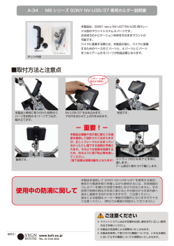
SCRIPT HOLDER
BKP-7911
電気製品は、安全のための注意事項を守らないと、
火災や人身事故になることがあります。
このオペレーションマニュアルには、事故を防ぐための重要な注意事項と製品
の取り扱いかたを示してあります。このオペレーションマニュアルをよくお読
みのうえ、製品を安全にお使いください。お読みになったあとは、いつでも見ら
れるところに必ず保管してください。
OPERATION MANUAL [Japanese/English]
1st Edition
Serial No. 11901 and higher
日本語
安全のために
電気製品は、安全のための注意事項を守らないと、火災や感電などにより死亡や
大けがなど人身事故につながることがあり、危険です。
警告表示の意味
事故を防ぐために次のことを必ずお守りください。
オペレーションマニュアルおよび
製品では、次のような表示をして
安全のための注意事項を守る
います。表示の内容をよく理解し
てから本文をお読みください。
4 ページの注意事項をよくお読みください。
定期点検をする
長期間安全に使用していただくために、定期点検を実施することをおすすめしま
す。点検の内容や費用については、ソニーのサービス担当者または営業担当者に
この表示の注意事項を守らないと、
ご相談ください。
感電やその他の事故によりけがを
したり周辺の物品に損害を与えた
故障したら使用を中止する
りすることがあります。
ソニーのサービス担当者、または営業担当者にご連絡ください。
行為を禁止する記号
万一、異常が起きたら
異常なにおい、煙が出たら
m
a スクリプトライトのコードを抜く。
b ソニーのサービス担当者または営業担当者に相談する。
行為を指示する記号
2
目次
注意 ......................................................................................................................4
概要...........................................................................................................................5
各部の名称.....................................................................................................5
取り付け ...................................................................................................................6
カメラへの取り付け ......................................................................................6
ペンホルダーの取り付け ...............................................................................6
バインダーの取り付け/取り外し.................................................................6
スクリプトライトの取り付け........................................................................7
使いかた ...................................................................................................................8
仕様...........................................................................................................................9
JP
目次
3
注意
可動部分をきちんと固定する
固定しないと、ホルダー自身が落下した
り積載物が落下して、けがをする可能性
があります。
重量物を乗せない
落下してけがをする可能性があります。
LED ランプを直視しない
LED ランプを直視すると目を傷める可
能性がありますので、長時間直視しない
でください。
4
注意
概要
BKP-7911 は、ソニーのカラービデオカメラ HDC1000、
ラージレンズアダプター HDLA1500、HDLA1505、および
ラージビューファインダーアダプター HDLA1507 などに取
り付けて使用するスクリプトホルダーです。BKP-7911 は日
めくり対応の台本台です。付属のスクリプトライトを取り
付けると、暗い場所でも台本をご覧になれます。
各部の名称
スクリプトライト
ライトシュー取り付け用穴
カールコード(カメラ
接続コネクター付き)
縦開き台本用バイ
ンダー取り付け穴
バインダー
明るさ調整つまみ
ライトシュー
ペンホルダー
台本おさえ
カメラへの取り付け部
概要
5
取り付け
カメラへの取り付け
カメラの左右どちらの側面にでも取り付けが可能です。
例:カメラ右側面(カメラマン側から見て左)に取り付ける場合
2
1
アクセサリー取り付け金具
ペンホルダーの取り付け
バインダーの取り付け/取り外し
3 個の穴のうちの 2 個を使用します。
台本が横開きか縦開きかによって、バインダーの位置を変
えることができます。工場出荷時には、横開きの台本用の
位置に取り付けられています。縦開きの台本を使用すると
きには、バインダーを縦開き用の位置に付けかえてくださ
い。
こちらの 2 個
への取り付け
も可能
6
取り付け
スクリプトライトの取り付け
スクリプトライトを取り付けるには
1
ライトシューを付け替えるには
BKP-7911 では、ライトシューの位置を変えることができま
す。工場出荷時には右側に取り付けられています。左側に
付け替えるときは、次の手順で行います。
スクリプトライトの土台部をライトシューにスライド
させて差し込み、土台部のネジを緩めて固定する。
1
ライトシューの板バネ固定用のネジを回して取り外し、
板バネをスライドさせて取り外す。
板バネ
土台部
ネジ
2
ネジ 4 本と板ナットを取り外す。
ライトシュー
2
カールコードの先のコネクターをカメラ右側面(カメ
ラマンから見て左)の DC OUT 端子に接続する。
板ナット
3
取り外したときと逆の手順でライトシューを左側の取
り付け用穴に取り付ける。
DC OUT 端子
取り付け
7
使いかた
例:横開き台本、スクリプトライト右側取り付け時
固定つまみをゆるめて、
ライトの角度を調整する
ライトの明るさを調整する
ペンホルダー
台本おさえ
バインダー
台本
8
使いかた
仕様
一般
質量
1.2 kg(スクリプトライト含む)
付属品
オペレーションマニュアル(1)
外形寸法
単位:mm
337
266
仕様および外観は、改良のため予告なく変更することがあ
りますが、ご了承ください。
お使いになる前に、必ず動作確認を行ってください。故
障その他に伴う営業上の機会損失等は保証期間中および
保証期間経過後にかかわらず、補償はいたしかねますの
でご了承ください。
仕様
9
English
Before operating the unit, please read this manual
thoroughly and retain it for future reference.
For the customers in Europe
This product with the CE marking complies with the EMC
Directive issued by the Commission of the European
Community.
Compliance with this directive implies conformity to the
following European standards:
• EN55103-1: Electromagnetic Interference(Emission)
• EN55103-2: Electromagnetic Susceptibility(Immunity)
This product is intended for use in the following
Electromagnetic Environments: E1 (residential),
E2 (commercial and light industrial), E3 (urban outdoors),
E4 (controlled EMC environment, ex. TV studio).
The manufacturer of this product is Sony Corporation, 17-1 Konan, Minato-ku, Tokyo, Japan.
The Authorized Representative for EMC and product
safety is Sony Deutschland GmbH, Hedelfinger Strasse
61, 70327 Stuttgart, Germany.
Pour les clients en Europe
Ce produit portant la marque CE est conforme à la
Directive sur la compatibilité électromagnétique (EMC)
émise par la Commission de la Communauté européenne.
La conformité à cette directive implique la conformité aux
normes européennes suivantes:
• EN55103-1: Interférences électromagnétiques
(émission)
• EN55103-2: Sensibilité électromagnétique (immunité)
Ce produit est prévu pour être utilisé dans les
environnements électromagnétiques suivants:
E1 (résidentiel), E2 (commercial et industrie légère),
E3 (urbain extérieur) et E4 (environnement EMC contrôlé,
ex. studio de télévision).
Le fabricant de ce produit est Sony Corporation, 1-7-1
Konan, Minato-ku, Tokyo, Japon.
Le représentant autorisé pour EMC et la sécurité des
produits est Sony Deutschland GmbH, Hedelfinger Strasse
61, 70327 Stuttgart, Allemagne.
Für Kunden in Europa
Dieses Produkt besitzt die CE-Kennzeichnung und erfüllt
die EMV-Richtlinie der EG-Kommission.
Angewandte Normen:
• EN55103-1: Elektromagnetische Verträglichkeit
(Störaussendung)
• EN55103-2: Elektromagnetische Verträglichkeit
(Störfestigkeit)
Für die folgenden elektromagnetischen Umgebungen: E1
(Wohnbereich), E2 (kommerzieller und in beschränktem
Maße industrieller Bereich), E3 (Stadtbereich im Freien)
und E4 (kontrollierter EMV-Bereich, z.B. Fernsehstudio).
Der Hersteller dieses Produkts ist Sony Corporation, 1-7-1
Konan, Minato-ku, Tokyo, Japan.
10
Der autorisierte Repräsentant für EMV und
Produktsicherheit ist Sony Deutschland GmbH,
Hedelfinger Strasse 61, 70327 Stuttgart, Deutschland.
Table of Contents
Overview......................................................................................... 12
Location of Parts and Controls ............................................................ 12
Setup............................................................................................... 13
Attaching to the Camera ...................................................................... 13
Attaching the Pen Holder..................................................................... 13
Changing the Binder’s Position ........................................................... 13
Attaching the Script Light ................................................................... 14
How To Use .................................................................................... 15
Specifications ................................................................................ 16
GB
Table of Contents
11
Overview
The BKP-7911 is a script holder designed for use with the
Sony HDC1000 Color Video Camera, HDLA1500 and
HDLA1505 Large Lens Adaptors, HDLA1507 Large
Viewfinder Adaptor, and so on. The BKP-7911 holds a
script bound at the top or side margin. The supplied script
light enables you to read a script even in the dark.
Location of Parts and Controls
Script light
Holes for attaching
the light shoe
Holes for attaching
the binder for scripts
bound at the top
Curl cord with
camera connector
Binder
Brightness
control
Light shoe
Pen holders
Paper clip
Camera attaching position
12
Overview
Setup
Attaching to the Camera
The BKP-7911 can be attached to either the left or right side of the camera.
Example: Attaching the BKP-7911 to the right side of the camera (operator’s left)
1
2
Accessory bracket
Attaching the Pen Holder
Changing the Binder’s Position
Use two of the three holes.
The binder is attached at the factory to the position for
scripts bound at the side margin. When using a script
bound at the top margin, shift the binder to the top.
or to these
holes
Setup
13
Attaching the Script Light
Attaching to the BKP-7911
1
Slide the base of the script light into the light shoe, and
tighten the screw on the button of the base to secure the
light.
Changing the light shoe’s position
For the BKP-7911, the light shoe can be attached to either
the left or right side. It is attached to the right side at the
factory. To attach it to the left side, proceed as follows.
1
Remove the screw and slide the spring plate to remove
it.
Spring plate
Base
Screw
2
Remove the four screws and plate nut.
Light shoe
2
Plug the connector of the curl cord into the DC OUT
connector on the right side of the camera (operator’s
left).
Plate nut
3
DC OUT connector
14
Setup
Attach the light shoe to the left side, reversing the
procedure for removing the light shoe.
How To Use
Example: for a script bound at the left, with the script light to the right
Adjust the lighting angle after
loosening the fixing knob.
Adjust the brightness of the script light.
Pen holders
Paper clip
Binder
Script
How To Use
15
Specifications
General
Mass
1.2 kg (2 lb 10 oz) (with the script light)
Supplied accessories
Operation Manual (1)
Dimensions
Unit: mm (inches)
337 (13 3/8)
266 (10 1/2)
Design and specifications are subject to change without
notice.
Note
Always verify that the unit is operating properly before
use. SONY WILL NOT BE LIABLE FOR
DAMAGES OF ANY KIND INCLUDING, BUT NOT
LIMITED TO, COMPENSATION OR
REIMBURSEMENT ON ACCOUNT OF THE LOSS
OF PRESENT OR PROSPECTIVE PROFITS DUE
TO FAILURE OF THIS UNIT, EITHER DURING
THE WARRANTY PERIOD OR AFTER
EXPIRATION OF THE WARRANTY, OR FOR ANY
OTHER REASON WHATSOEVER.
16
Specifications
このマニュアルに記載されている事柄の著作権は当社にあ
り、説明内容は機器購入者の使用を目的としています。
従って、当社の許可なしに無断で複写したり、説明内容
(操作、保守等)と異なる目的で本マニュアルを使用するこ
とを禁止します。
Sony Corporation expressly prohibits the duplication of any
portion of this manual or the use thereof for any purpose other
than the operation or maintenance of the equipment
described in this manual without the express written
permission of Sony Corporation.
Sony Corporation
BKP-7911 (WW)
4-413-921-01(1)
Printed in Japan
2011.09 08
© 2011
© Copyright 2026 Paperzz