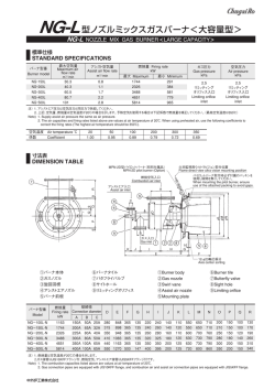
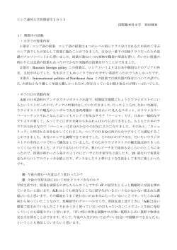
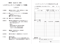
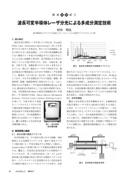
CB-129-02L
HSGB 型ハイスピードガスバーナ
HSGB HIGH SPEED GAS BURNER
小型、軽量でスリムなタイルレス。火炎速度が高速、中速、低速、自由自在。
Compact, light, tileless. Selective flame speed.
小型、軽量でスリムなタイルレスのダイレクト点火式ガスバーナです。火炎速度が高速から低速まで自
由に選べ、低空気比燃焼から超過剰空気燃焼まで使用できます。また、取付が簡単でメンテナンスが
容易なため、あらゆる炉設備の熱源としてご使用いただけます。
The HSGB high speed gas burner is a compact, light and tileless direct ignited gas burner.
In a broad range of flame speeds, it can provide a variety of firing from low to superexcess
air ratio combustion. Simple mounting and easy maintenance enables versatile uses of this
burner for all types of furnaces.
用 途
APPLICATIONS
窯業用連続炉(ローラーハースキルン、トンネルキルン)、バッ
チ炉(シャットルキルン、コーナージェットキルン)、金属加熱・熱
処理炉、硝子加熱・加工・熱処理炉、乾燥炉、エアヒータ、脱
臭炉、焼却炉、ラジアントチューブ、環境関連設備など、低温炉
から高温炉まで幅広く使用できます。
Continuous furnaces for ceramics (roller hearth kilns,
tunnel kilns), batch furnaces for ceramics (shuttle kilns,
corner jet kilns), metal heating furnaces, metal heat
treating furnaces, glass furnaces and lehrs, air heaters,
thermal oxidizers, incinerators, radiant tubes, pollution
control equipment, and other low and high temperature
furnaces.
1
特 長
FEATURES
1. 小型、軽量でスリムなタイルレス構造
バーナタイルを持たないため、小型、軽量でスリムなガスバーナで
す。従来のようなバーナタイル破損によるトラブルがなく、炉体へ
の取付け、取外しが極めて簡単で、作業性、
メンテナンス性に優
れています。
●炉体に穴があれば簡単にバーナの取付けができます。
2. 火炎速度が自由に選べる
コンバスターを交換するだけで火炎速度が高速(H型.130m/s)
、
中速(M型.80m/s)
、低速(L型.40m/s)の3段階の中から自由に
選べます。(交換は簡単に行えます。)
●炉気撹拌が必要な炉から必要でない炉まで、どのような炉にも
ご使用いただけます。
3. 低空気比燃焼から超過剰空気燃焼まで可能
低空気比燃焼(空気比m=1.05)から、超過剰空気燃焼(空気
比m=8.0:ガスコン制御時)
まで使用でき、制御も簡単です。
●比例制御(ターンダウン10:1)、ガスコン制御およびON-OFF
制御が使用できます。
4. ダイレクト点火で火炎監視が可能
電気点火によるノンパイロット方式のガスバーナで、光電管式と
フレームロッド式の両方式の火炎監視装置が使用でき、安全性
に優れています。(75A、100Aを除く)
5. バーナ取付部の表面温度が低い
従来のバーナに比べバーナ取付部(バーナ本体)の表面温度が
低く、省エネルギー効果があると共に、作業環境の改善にもなり
ます。
6. バーナ長さが自由に選べる
炉壁の厚さに応じて、バーナ長さが自由に選べます。
●厚い炉壁から薄い炉壁まで対応できます。
7. 高温予熱空気が使える
500℃までの高温予熱空気が燃焼空気として使用できますので、
省エネルギー化が図れます。
8. オイルバーナに変更可能
ガスノズルアッセンブリをオイルスプレイヤアッセンブリに交換する
ことで、簡単にオイルバーナ(灯油)
として使用できます。
9. 各種ガス燃料に対応
都市ガス、天然ガス、
ブタンガス、
プロパンガス、
ブタンエアガス、
プ
ロパンエアガスなどが使用できます。
2
1.Tileless design
The burner is compact and light because of no tile. Unlike
the conventional gas burner the HSGB burner is free from
the trouble of burner tile damage, and it is very easy to
mount or remove, and is excellent in operability and
maintenance.
●This burner can be easily fitted to a furnace if a hole
exists in its shell.
2.Free choice of flame speeds
An easy change of a combustor only allows free choice of
a desired flame speed from three speeds - 130m/sec.(high
speed), 80m/sec.(medium speed) and 40m/sec.(low
speed).
●The burner is applicable to any furnace, whether or not
the furance atmosphere should be agitated.
3.Applicable to a broad range of firing
The burner can be used for a variety of firing from low air
ratio combustion (excess air ratio:1.05) to super excess air
ratio combustion (excess air ratio:8.0)(gas control), with
easy control.
●Proportioning control(turndown ratio:10:1), gas control
and on-off control are available.
4.Direct ignition system enabling flame monitoring
The electric direct ignition system eliminating a pilot burner
enables either a phototube or rod type flame monitor to be
used, ensuring highly safe operation. *Except 75A, 100A
5.Low surface temperature of burner mount
The HSGB burner is lower in the mount surface
temperature than the conventional burner. This has a good
effect on energy savings and also results in improvement
in a working environment.
6.Free burner length
The burner length can be freely selected according to the
furnace wall thickness.
7.Preheated air of high temperature usable
Preheated air of high temperatures up to 500℃ can be
used, resulting in fuel savings.
8.Convertible to oil burner
The gas burner can be easily changed to an oil burner by
only replacing the gas nozzle assembly with an oil sprayer
assembly.
9.Usable with a variety of gaseous fuels
The burner is effective with various gaseous fuels such as
town gas, natural gas, butane gas, propane gas, butane
air gas, propane air gas, etc.
HSGB 型ハイスピードガスバーナ
HSGB
HIGH SPEED GAS BURNER
標準構成
STANDARD COMPONENTS
① バーナ本体
② コンバスター
③ スパークプラグ
④ キャブタイヤコード
⑤ 点火トランス
⑥ サイトホール
⑦ エアバタフライバルブ
⑧ 比率調整バルブ
⑨ 開閉バルブ
⑩ 火炎監視装置(特別付属品)
①
⑦
⑥
① Burner body
② Combustor
③ Spark plug
④ Cabtyre cord
⑤ Ignition transformer
⑥ Sight hole
⑦ Air butterfly valve
⑧ Ratio control valve
⑨ Gas valve
⑩ Flame detector (option)
②
⑩
③
④
⑧
⑤
⑨
型番記号説明
DESIGNATION
HSGB
記号 バーナサイズ 記号 燃 料 種 類
Symbol Burner size Simbol Type of Fuel
3
5
10
15
20
30
50
75
100
標準9種類
9 standard
sizes
20
A
LP
H
燃 料 種 類
Type of Fuel
記号
Symbol
A1 ブタンエアガス Butane air gas 33MJ/m(normal)
LB ブタンガス
Butane gas
A2
〃
〃
38MJ/m(normal)
A3
〃
〃
42MJ/m(normal)
N1 天然ガス
Natural gas
A4
〃
〃
46MJ/m(normal)
N2 都市ガス 12A
Town gas 12A
A5
〃
〃
50MJ/m(normal)
A6
〃
〃
54MJ/m(normal)
A7
〃
〃
59MJ/m(normal)
A8
〃
〃
63MJ/m(normal)
N4 LNGエアガス
LNG air gas
300
記号 コンバスター形状
Symbol Combustor shape
LP プロパンガス
Propane gas
N3 都市ガス 13A
Town gas 13A
C
3
H
(130m/s)
高速
High speed(130m/sec.)
M
中速
( 80m/s)
Medium speed( 80m/sec.)
L
( 40m/s)
低速
Low speed( 40m/sec.)
3
3
3
3
3
U
記号 コンバスター材質
Symbol Combustor material
C セラミック Ceramic
M メタリック Metallic
バーナ長さ
(㎜)
Burner length(㎜)
記号
Symbol
U
光電管式
Flame eye
L
フレームロッド式
Flame rod
ー
なし
None
3
3
注)1. ブタンエアガスをご使用の際は発熱量と組成(または密度)
をご連絡ください。
またその他の燃焼ガス
(各種副生ガス)
をご使用の際は、ご相談ください。
2. 上記以外のコンバスター材質をご要求の場合はご指示ください。
火炎監視装置
Flame detector
Note) 1. When using butane air gas, inform us of its calorific value and composition(or density).
If you intend to use other fuel gasses(various by-product gases), please contact us.
2. If you reqire the besides combustor material, please indicate us.
3
取付寸法
MOUNTING DIMENSIONS
サイトホール Sight hole
J-φK
スパークプラグ
Spark plug
光電管、
またはフレームロッド
Flame eye or flame rod
空気入口 Air inlet
A
B
空気入口 Air inlet
セラミックファイバー充填
Filled with ceramic fiber
ガス入口 Gas inlet
Burner model
A
HSGB― 3A L+205
HSGB― 5A L+205
HSGB― 10A L+240
HSGB― 15A L+285
HSGB― 20A L+305
HSGB― 30A L+315
HSGB― 50A L+375
HSGB― 75A L+395
HSGB―100A L+395
φN
φG
ガス入口 Gas inlet
HSGB-15A,20A,30A,50A,75A,100A
バーナ型番
φE
P.C.D
F
I
H
H
I
M
バーナ長さL
Burner length“L”
φG
C
取付穴参考寸法
Mounting hole size
(reference)
D
HSGB-3A,5A,10A
HSGB-3A,5A,10A,20A,30A
HSGB-50A
バーナ長さL
接管径
Pipe connection 最小寸法
Burner
B
C
D
φE
F
φG
H
I
J
φK
M
φN
60
60
80
115
130
130
170
167
167
60
60
70
80
85
90
105
123
123
85
85
90
90
90
95
100
105
105
200
200
235
265
300
320
385
385
385
165
165
200
230
260
280
345
345
345
85
85
110
125
148
175
215
−
−
45
45
60
60
60
70
80
85
85
90
90
100
120
140
160
180
205
205
4
4
8
8
8
8
12
12
12
14
14
14
14
14
14
18
18
18
9
9
9
12
12
12
14
14
14
125 Rc11/2 Rc3/8
125 Rc11/2 Rc3/8
150 Rc 2 Rc1/2
180 65A Rc3/4
200 80A Rc3/4
225 80A Rc 1
265 100A Rc11/4
280 125A Rc11/2
290 125A Rc11/2
注)1. バーナ長さ
(L寸法)
はご連絡ください。
2. 質量は、バーナ長さ
(L寸法)が最小寸法の場合を示します。
3. 75A,100Aはパイロットバーナ点火、バーナタイル方式を標準とします。
Note) 1. The burner length(dimension"L") depends on the thickness of your furnace wall. Please inform us of the thickness in advance.
2. The weight shown is that of a burner of the minimum length (dimension"L").
3. The standard method of HSGB-75A and 100A is by pilot burner and burner tile.
4
質量
length L Weight
空気 Air ガス Gas (minimum)
245
245
245
300
300
350
350
350
350
10kg
10kg
15kg
20kg
25kg
30kg
50kg
60kg
65kg
HSGB 型ハイスピードガスバーナ
HSGB
HIGH SPEED GAS BURNER
構造説明
CONSTRUCTION
燃焼空気は空気入口よりエアパイプを通り、
スタビライザーより流出します。燃料ガスはガス入口よりガスパイプを通り、
ガスノズルより流出
します。
流出した空気およびガスはコンバスター内で混合し、
スパークプラグの電極部で点火され燃焼し、
コンバスターより火炎を吐出します。
Combustion air entering the air inlet flows through the air pipe and stabilizer. Fuel gas entering the gas inlet flows through
the gas pipe and gas nozzle.
The combustion air and the fuel gas are mixed inside the combustor and ignited by the electrode of the spark plug,
producing flames.
空気入口 Air inlet
エアパイプ
フェイスプレート
Face plate
Air pipe
ガスパイプ Gas pipe
スパークプラグ電極部
Electrode of spark plug
コンバスター
Combustor
スパークプラグ
Spark plug
ガスノズル Gas nozzle
スタビライザー Stabilizer
ガス入口
Gas inlet
バーナ本体
Burner body
チャックナットまたはフランジ
Chuck nut or flange
標準仕様
STANDARD SPECIFICATIONS
バーナ型番
Burner model
HSGB- 3A
HSGB- 5A
HSGB- 10A
HSGB- 15A
HSGB- 20A
HSGB- 30A
HSGB- 50A
HSGB- 75A
HSGB-100A
Pressure
圧力 kPa
燃焼量 Firing rate kW 空気比範囲
最大空気量
H type
M type
L type
H型
M型
L型
Max. air flow
Excess air
最大
最小
m3/min(normal) Maximum Minimum ratio range 空気 Air ガス Gas 空気 Air ガス Gas 空気 Air ガス Gas
35
3.5
0.66
58
6.0
1.1
116
12.0
2.2
1.05
175
17.5
3.3
∼
4
3
3
2
2.5
1.5
233
23.0
4.4
8.0
348
35.0
6.6
582
60.0
11.0
872
87.0
16.5
1163
116.0
22.0
空気温度 Air temperature ℃ 20 100 200 300 400 500
Coefficient 1.00 0.89 0.79 0.71 0.66 0.62
係数
注)1. 上記空気量および燃焼量は、空気温度20℃、空気比1.2の場合を示します。
予熱空気をご使用の場合は、右記係数で燃焼量を補正してください。
2. 空気比範囲は、比例制御(1.05∼1.3)とガスコン制御(1.3∼8.0)の範囲を示します。
空気比範囲が1.0未満または8.0以上で使用される場合は、ご相談ください。
3. 上記H型、M型、L型は、コンバスターの形状を示す型番です。
4. HSGB-3A、5A、10Aの空気入口とバタフライバルブの取合いは、ユニオン取合いとしてください。
Note) 1. The air flow and firing rate listed above are values in proportining control with air temperature of 20℃ and excess air ratio of 1.2.
When preheated air is used, correct the firing rate with the coefficient given on the right.
2.Excess air ratio range shows range of proportining control(1.05∼1.3) and range of gas control(1.3∼8.0).
If you require excess air ratio less than 1.0 or more than 8.0, please contact us.
3. The above H, M and L types indicate the models of the combustors.
4. Joints the air butterfly valve to the air inlet of HSGB-3A, 5A and 10A models are jointed by union.
5
火炎形状
NOx特性
FLAME DIMENSIONS
NOx CHARACTERISTICS
HSGB― 3A
HSGB― 5A
HSGB― 10A
HSGB― 15A
HSGB― 20A
HSGB― 30A
HSGB― 50A
HSGB― 75A
HSGB―100A
コンバスター型式(フレーム径φDmm×フレーム長さLmm)
Flame diameter:φDmm×Flame lenghth:Lmm
L type
L型
M型 M type
H型 H type
φ 60× 300
φ 50× 250
φ 40× 200
φ 80× 400
φ 60× 350
φ 50× 300
φ120× 500
φ 90× 475
φ 60× 450
φ150× 600
φ110× 500
φ 80× 450
φ200× 700
φ 90× 500
φ120× 550
φ250×1000
φ150× 700
φ170× 800
φ300×1600
φ180×1150
φ220×1300
φ340×1800
φ210×1300
φ250×1500
φ380×2000
φ230×1450
φ280×1650
50
NOx(ppm,O2=11%換算)
(ppm,O2=11%correction)
バーナ型番
Burner model
30
20
L型コンバスター
L type combustor
M型コンバスター
M type combustor
H型コンバスター
H type combustor
10
0
0
●燃焼条件/燃焼負荷率:100% 燃料:LPG、都市ガス13A
炉内温度:700℃ 空気比:m=1.2 目視確認
●Firing conditions/Burner load :100% Fuel:LPG, Town gas 13A
Furnace temperature:700℃ Excess air ratio:1.2
Flame diameter and flame length determined by eyes
40
50
燃焼負荷率(%) Burner load
100
●測定条件/空気比:m=1.2
炉内温度: 800℃
(低負荷時)
1100℃
(高負荷時)
φD
●Firing conditions/
Excess air ratio:1.2
Furnace temperature: 800℃(Low load)
1100℃(High load)
L
標準付属品
STANDARD ACCESSORIES
開閉バルブおよび比率調整バルブ
Gas valves
バーナ型番
Burner model
エアバタフライバルブ
Air butterfly valve
LP,LB,N2,N3,A5∼A8
N1,N4,A1∼A4
HSGBー 3A
BVー 40
GBCー10
GBCー10
HSGBー 5A
BVー 40
GBCー10
GBCー10
HSGBー 10A
BVー 50
GBCー15
GBCー20
スパークプラグ
Spark plug
点火トランス
Ignition transformer
GS型
GS type
HSGBー 15A
FBVー 65
GBCー20
GBCー25
TS型
HSGBー 20A
FBVー 80
GBCー20
GBCー25
TS type
HSGBー 30A
FBVー 80
GBCー25
GBCー32
HSGBー 50A
FBVー100
GBCー32
GBCー40
HSGBー 75A
FBVー125
GBCー40
GBCー50
HSGBー100A
FBVー125
GBCー40
GBCー50
注)1. 空気温度80℃以上でご使用の場合は、エアバタフライバルブがH-FBV型に
なります。
2. ガスバルブは比率調整バルブ1ケ、開閉バルブ1ケの合計2ケ付属します。
3. 上記LP、LB、N1∼N4、A1∼A8は燃料種類を示す型番です。
キャブタイヤコード
Cabtyre cord
強化シリコンゴム
絶縁電線
2m
Reinforced
silicone rubber
insulated cable
2m
Note) 1. The type of the air butterfly valve is H-FBV when the
burner is operated at an air temperature exceeding 80℃.
2. One ratio control valve and one on-off valve are provided
as the gas valves.
3. The above LP, LB, N1-N4, A1-A8 types indicate the
types of the fuel.
特別付属品
SPECIAL ACCESSOIES
①火炎監視装置(光電管式またはフレームロッド式)
②制御機器(ガス均圧弁、ガスコントロールバルブ、
エアコントロー
ルバルブ)
③ガス流量オリフィス、エア流量オリフィス
④制御盤
6
①Flame detector (phototube type or rod type)
②Controls (gas pressure equalizing valve, gas control
valve, air control valve)
③Gas flow orifice, air flow orifice
④Control panel
HSGB 型ハイスピードガスバーナ
HSGB
HIGH SPEED GAS BURNER
配管系統図例
PIPING DIAGRAMS
①比例制御方式
均圧弁により空気とガスが常に同圧に保たれますので、空気側コントロールバルブの操作だけで、空気比を一定にしたまま、燃焼量の調
節が行えます。
(※比率調整バルブにて比率設定)
1. Proportioning control system
The pressure equalizing valve holds the air and gas at the same pressure.
Therefore, the firing rate can be adjusted with the excess air ratio kept constant by operating the air line control valve only.
(*Excess air ratio setting by the ratio control valve)
圧力計 Pressure gauge
温度指示調節計
Temperature indicating controller
熱電対
Thermocouple
各バーナへ
To each burner
エアコントロールバルブ
Air control valve
圧力スイッチ(下限)
Pressure switch(lower limit)
P
圧力計
Pressure gauge
P
P.S L
エアオリフィス Air orifice
ターボブロワ
Turbo blower
ローディングパイプ Loading pipe
最小流量限定バルブ
Minimum flow limiting valve
圧力スイッチ(下限・上限)
Pressure switch(lower limit and upper limit)
ガス流量計
Gas flowmeter
P
HSGBバーナ
HSGB burner
P
圧力計 Pressure gauge
圧力計
Pressure gauge
エアバタフライバルブ
Air butterfly valve
微圧計
Pressure gauge
P
検圧口
Pressure measurement point
P.S L P.S H
点火プラグ Spark plug
火炎監視装置 Flame detector
各バーナへ 点火トランス
To each burner Ignition
transformer
微圧計
Pressure gauge
P
比率調整バルブ
Ratio control valve
ガス Gas
ガス元バルブ
Main gas valve
ガス遮断弁
Gas shutoff valve
ストレーナ
Strainer
ガス均圧弁
Gas pressure equalizing valve
開閉バルブ Burner side gas valve
バイパスバルブ
Bypass valve
ガス電磁弁 Gas solenoid valve
ガスオリフィス Gas orifice
検圧口 Pressure measurement point
②ガスコン制御方式
ガスコントロールバルブのみ操作することで、燃焼量の調節が行えます。
2. Gas flow control system
The firing rate can be adjusted and the excess air ratio can be freely changed, by operating the gas control valve only.
圧力スイッチ(下限)
Pressure switch(lower limit)
圧力計 Pressure gauge
P
P.S L
エアバルブ
Air control valve
圧力計
Pressure gauge
各バーナへ
To each burner
エアバタフライバルブ
Air butterfly valve
ガスコントロールバルブ
Gas control valve
微圧計
Pressure gauge
圧力計
Pressure
gauge
圧力スイッチ(下限・上限)
Pressure switch(lower limit and upper limit)
検圧口
Pressure measurement point
P
P.S L P.S H
ガス流量計
Gas flowmeter
ストレーナ
Strainer
バイパスバルブ Bypass valve
スパークプラグ Spark plug
P
火炎監視装置
To each Flame detector
burner
点火トランス
各バーナへ
Ignition transformer
ガス遮断弁
Gas shutoff valve
最小流量限定バルブ
Minimum flow limiting valve
HSGBバーナ
HSGB burner
P
ガス Gas
ガス元バルブ
Main gas valve
温度指示調節計
Temperature indicating controller
熱電対
Thermocouple
エアオリフィス
Air orifice
ターボブロワ
Turbo blower
圧力計
Pressure gauge
P
P
微圧計
Pressure gauge
比率調整バルブ
Ratio control valve
ガスオリフィス Gas orifice
ガス電磁弁 Gas solenoid valve
検圧口
Pressure measurement point
開閉バルブ Burner side gas valve
7
HSGB 型ハイスピードガスバーナ
HSGB
HIGH SPEED GAS BURNER
③EBC-i制御方式(EBC-i自動空気比制御システム)
操炉条件に最適な燃焼パターンをEBC-iが精密制御します。勘と経験に頼らざるを得なかった現場での燃焼調整が不要となります。
3. EBC-i control system
The EBC-i allows precision control of the optimum combustion pattern for the furnace operating conditions. This system
eliminates field combustion adjustment, which has inevitably been dependent on intuition and experience.
圧力スイッチ(下限)
Pressure switch(lower limit)
圧力計
Pressure gauge
EBC-i 制御器
EBC-i controller
P
モニタ
Monitor
P
圧力計
Pressure gauge
各バーナへ
To each burner
P.S L
温度指示調節計
Temperature indicating controller
熱電対
Thermocouple
ターボブロワ
Turbo blower
エアコントロールユニット
Air control unit
検圧口
Pressure measurement point
圧力計
Pressure gauge
P
各バーナへ
To each burner
P.S L P.S H
火炎監視装置
Flame detector
圧力計
Pressure gauge
ガス Gas
ガス元バルブ
Main gas valve
HSGB バーナ
HSGB burner
スパークプラグ
Spark plug
圧力スイッチ(上限・下限)
Pressure switch
(upper and lower limit)
P
ガスコントロールユニット
Gas control unit
点火トランス
Ignition transformer
ガス電磁弁
Gas solenoid valve
各バーナへ
ストレーナ
Strainer
ガス遮断弁 Gas shutoff valve
開閉バルブ Burner side gas valve
To each
burner
検圧口 Pressure measurement point
④ON-OFF制御にもご使用いただけます。
4. Burner on-off control is also available.
システムフロー
SYSTEM FLOW
起動
Start of operation
点火
Main burner ignition
消火(または異常失火) (警報停止)
停止
Extinction(or abnomal flame failure) Alarm stop
Stop of operation
排気ファン・空気ブロワ
Exhaust fan, air blower
点火トランス
Ignition transformer
電磁弁
Solenoid valve
火炎信号
Flame signal
警報ブザー
Alarm buzzer
異常失火時のみ
(Only against abnormal
flame failure)
本製品に関する特許:特許第2777106号、特許第2944579号
Patent for this product : JP277106, JP2944579
※ 本カタログはSI単位を採用しています。従来単位とは下記数式にて換算してください。
*This catalog uses the SI units which can be calculated from the following formula:
●1kcal/h=1.163×10-3kW 1kW=860kcal/h ●1kcal=4.18kJ(10000kcal=41.8MJ) 1kJ=0.239kcal(1MJ=239kcal) ●1mmH2O=1kg/m2=9.81Pa(1kg/㎝2=98.1kPa) 1Pa=0.102mmH2O(1kPa=102mmH2O)
安全に関するご注意:ご使用の際は、取扱説明書をよくお読みの上、正しくお使いください。
SAFETY PRECAUTIONS : Read the instruction manual carefully before using the equipment.
URL http://www.chugai.co.jp
堺 事 業 所 〒592-8331 堺市西区築港新町2丁4番
(072)247-1440
(直通) FAX(072)247-1441
サーモシステム事業部 TEL
Sakai Works : 2-4,Chikko-Shinmachi,Nishi-ku,Sakai 592-8331,Japan
Tel +81-72-247-1440 Fax +81-72-247-1441
東 京 支 社 〒108-0075 東京都港区港南2丁目5番7号(港南ビル)
サーモシステム事業部 TEL(03)5783-3378(直通) FAX(03)5783-3368
Tokyo Branch : 2-5-7,Konan,Minato-ku,Tokyo 108-0075,Japan
Tel +81-3-5783-3378 Fax +81-3-5783-3368
名古屋営業所 〒450-0003 名古屋市中村区名駅南1丁目21番19号(本州名駅ビル)
TEL(052)561-3561(代表) FAX(052)561-3566
Nagoya Sales Office: 1-21-19,Meieki-Minami,Nakamura-ku,Nagoya 450-0003,Japan
Tel +81-52-561-3561 Fax +81-52-561-3566
燃 焼 研 究 所 〒582-0027 大阪府柏原市円明町1000番地6
TEL(072)977-8503(代表) FAX(072)978-6981
Combustion Laboratory: 1000-6,Enmyo-cho,Kashiwara,Osaka 582-0027,Japan
Tel +81-72-977-8503 Fax +81-72-978-6981
●記載内容について、改良のため予告なしに変更する場合もありますので、あらかじめご了承ください。
●The descriptions and specifications are subject to change without notice.
8
160610(M) Printed in Japan
© Copyright 2026 Paperzz