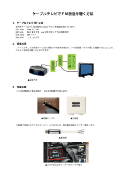
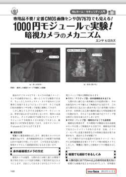
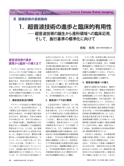
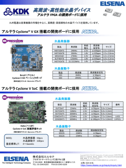
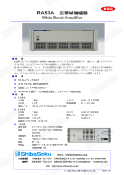
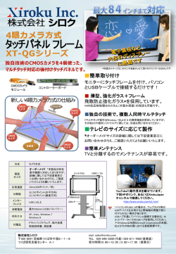
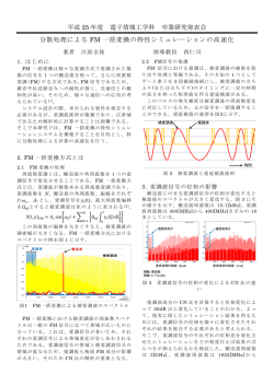
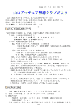
S i 5 1 0 / 5 11 水 晶発振 器 ( X O ) 100 k H Z ∼ 2 5 0 M H Z 機能 100 kHz ∼ 250M Hz 範囲のすべ ての周波数をサポート 低ジッタ動作 2 ∼ 4 週間のリードタイム 10 年エージングを含む総合安 定度 水晶 ESR と DLD を含む包括的 な生産試験範囲 電源ノイズをフィルタするオン チップの LDO レギュレータ 3.3、2.5、または 1.8 V 動作 差動 (LVPECL、LVDS、HCSL) または CMOS の出力オプション オプションの内蔵 1:2 CMOS ファンアウト・バッファ OE および電源投入時のラント抑 制機能 業界標準の 5 x 7 および 3.2 x 5 mm パッケージ 鉛フリー対応、RoHS 準拠 –40 ∼ 85 oC で動作 Si5602 Ordering Information: See page 14. アプリケーション SONET/SDH/OTN ギガビット・イーサネット ファイバ・チャネル /SAS/SATA PCI Express 3G-SDI/HD-SDI/SDI テレコム スイッチ / ルーター FPGA/ASIC クロック生成 Pin Assignments: See page 12. 説明 Si510/511 XO は、Silicon Laboratories の高度な DSPLL 技術を利用して、 100 kHz ∼ 250 MHz 範囲のすべての周波数を提供します。出力周波数ごと に異なる水晶が必要な従来の XO とは違い、Si510/511 は 1 つの固定水晶と Silicon Labs 独自の DSPLL シンセサイザを使用して、この周波数範囲のす べての周波数を生成します。この IC ベースのアプローチにより、水晶共振 器の優れた信頼性、機械的な耐久性の向上、高い安定度が実現しています。 さらに、本ソリューションは優れた電源ノイズ除去性能を備えているため、 ノイズの多い環境で低ジッタ・クロック生成を簡素化できます。水晶 ESR と DLD の生産テストは、高い性能の保証と信頼性の向上のために個別に実 行されます。Si510/511 では、周波数、供給電圧、出力形式、出力イネーブ ル極性、安定度など、幅広いユーザ設定を工場出荷時に構成できます。詳細 な構成は出荷時に工場でプログラムされるため、カスタム周波数発振器に伴 う長いリードタイムや、単発的なエンジニアリング費用を排除できます。 機能ブロック・ダイアグラム VDD OE 1 4 VDD GND 2 3 CLK Si510 (CMOS) NC 1 6 VDD OE 2 5 CLK– GND 3 4 CLK+ Si510 (LVDS/LVPECL/HCSL/ Dual CMOS) Low Noise Regulator Fixed Frequency Oscillator Any-Frequency 0.1 to 250 MHz DSPLL® Synthesis CLK+ CLK– GND 改訂 1.2 7/15 OE Copyright © 2015 by Silicon Laboratories OE OE 11 66 V VDD DD NC NC 22 55 CLK– CLK– GND GND 33 44 CLK+ CLK+ Si511 (LVDS/LVPECL/HCSL/ Dual CMOS) Si510/511 Si510/511 2 改訂 1.2 Si510/511 目次 セクション ページ 1. 電気仕様 . . . . . . . . . . . . . . . . . . . . . . . . . . . . . . . . . . . . . . . . . . . . . . . . . . . . . . . . . . . . . . . . .4 2. ピンの説明 . . . . . . . . . . . . . . . . . . . . . . . . . . . . . . . . . . . . . . . . . . . . . . . . . . . . . . . . . . . . . . 12 2.1. デュアル CMOS バッファ . . . . . . . . . . . . . . . . . . . . . . . . . . . . . . . . . . . . . . . . . . . . . 13 3. 注文情報 . . . . . . . . . . . . . . . . . . . . . . . . . . . . . . . . . . . . . . . . . . . . . . . . . . . . . . . . . . . . . . . . 14 4. Si510/511 マーク仕様 . . . . . . . . . . . . . . . . . . . . . . . . . . . . . . . . . . . . . . . . . . . . . . . . . . . . . 15 5. パッケージ外形図 : 5 x 7 mm、4 ピン . . . . . . . . . . . . . . . . . . . . . . . . . . . . . . . . . . . . . . . . 16 6. PCB ランド・パターン : 5 x 7 mm、4 ピン . . . . . . . . . . . . . . . . . . . . . . . . . . . . . . . . . . . . 17 7. パッケージ外形図 : 5 x 7 mm、6 ピン . . . . . . . . . . . . . . . . . . . . . . . . . . . . . . . . . . . . . . . . 18 8. PCB ランド・パターン : 5 x 7 mm、6 ピン . . . . . . . . . . . . . . . . . . . . . . . . . . . . . . . . . . . . 19 9. パッケージ外形図 : 3.2 x 5 mm、4 ピン . . . . . . . . . . . . . . . . . . . . . . . . . . . . . . . . . . . . . . 20 10. PCB ランド・パターン : 3.2 x 5 mm、4 ピン . . . . . . . . . . . . . . . . . . . . . . . . . . . . . . . . . . 21 11. パッケージ外形図 : 3.2 x 5 mm、6 ピン . . . . . . . . . . . . . . . . . . . . . . . . . . . . . . . . . . . . . . 22 12. PCB ランド・パターン : 3.2 x 5.0 mm、6 ピン . . . . . . . . . . . . . . . . . . . . . . . . . . . . . . . . 23 文書変更リスト . . . . . . . . . . . . . . . . . . . . . . . . . . . . . . . . . . . . . . . . . . . . . . . . . . . . . . . . . . . . . 24 改訂 1.2 3 Si510/511 1. 電気仕様 表 1. 動作仕様 VDD = 1.8 V ±1 5%、2.5 または 3.3 V ±10%、TA = –40 ∼ +85 oC Parameter Supply Voltage Supply Current Symbol Test Condition Min Typ Max Unit VDD 3.3 V option 2.97 3.3 3.63 V 2.5 V option 2.25 2.5 2.75 V 1.8 V option 1.71 1.8 1.89 V CMOS, 100 MHz, single-ended — 21 26 mA LVDS (output enabled) — 19 23 mA LVPECL (output enabled) — 39 43 mA HCSL (output enabled) — 41 44 mA Tristate (output disabled) — — 18 mA IDD OE "1" Setting VIH See Note 0.80 x VDD — — V OE "0" Setting VIL See Note — — 0.20 x VDD V OE Internal Pull-Up/PullDown Resistor* RI — 45 — k Operating Temperature TA –40 — 85 oC *Note: Active high and active low polarity OE options available. Active high option includes an internal pull-up. Active low option includes an internal pull-down. See ordering information on page 14. 4 改訂 1.2 Si510/511 表 2. 出力クロック周波数の特性 VDD = 1.8 V ±5%、2.5 または 3.3 V ±10%、TA = –40 ∼ +85 oC Parameter Nominal Frequency Symbol Test Condition Min Typ Max Unit FO CMOS, Dual CMOS 0.1 — 212.5 MHz FO LVDS/LVPECL/HCSL 0.1 — 250 MHz Frequency Stability Grade C –30 — +30 ppm Frequency Stability Grade B –50 — +50 ppm Frequency Stability Grade A –100 — +100 ppm Frequency Stability Grade C –20 — +20 ppm Frequency Stability Grade B –25 — +25 ppm Frequency Stability Grade A –50 — +50 ppm Total Stability* Temperature Stability Startup Time TSU Minimum VDD until output frequency (FO) within specification — — 10 ms Disable Time TD FO 10 MHz — — 5 µs FO < 10 MHz — — 40 µs FO 10 MHz — — 20 µs FO < 10 MHz — — 60 µs Enable Time TE *Note: Total stability includes initial accuracy, operating temperature, supply voltage change, load change, shock and vibration (not under operation), and 10 years aging at 40 oC. 改訂 1.2 5 Si510/511 表 3. 出力クロック・レベルと対称性 VDD = 1.8 V ±5%、2.5 または 3.3 V ±10%、TA = –40 ∼ +85 oC Parameter Symbol Test Condition Min Typ Max Unit CMOS Output Logic High VOH 0.85 x VDD — — V CMOS Output Logic Low VOL — — 0.15 x VDD V CMOS Output Logic High Drive IOH 3.3 V –8 — — mA 2.5 V –6 — — mA 1.8 V –4 — — mA 3.3 V 8 — — mA 2.5 V 6 — — mA 1.8 V 4 — — mA 0.1 to 212.5 MHz, CL = 15 pF 0.45 0.8 1.2 ns 0.1 to 212.5 MHz, CL = no load 0.3 0.6 0.9 ns CMOS Output Logic Low Drive IOL CMOS Output Rise/Fall Time (20 to 80% VDD) TR/TF LVPECL Output Rise/Fall Time (20 to 80% VDD) TR/TF 100 — 565 ps HCSL Output Rise/Fall Time (20 to 80% VDD) TR/TF 100 — 470 ps LVDS Output Rise/Fall Time (20 to 80% VDD) TR/TF 350 — 800 ps LVPECL Output Common Mode VOC 50 to VDD – 2 V, single-ended — VDD – 1.4 V — V LVPECL Output Swing VO 50 to VDD – 2 V, single-ended 0.55 0.8 0.90 VPPSE LVDS Output Common Mode VOC 100 line-line VDD = 3.3/2.5 V 1.13 1.23 1.33 V 100 line-line, VDD = 1.8 V 0.83 0.92 1.00 V LVDS Output Swing VO Single-ended, 100 differential termination 0.25 0.35 0.45 VPPSE HCSL Output Common Mode VOC 50 to ground 0.35 0.38 0.42 V HCSL Output Swing VO Single-ended 0.58 0.73 0.85 VPPSE Duty Cycle DC All formats 48 50 52 % 6 改訂 1.2 Si510/511 表 4. 出力クロックのジッタと位相ノイズ (LVPECL) VDD = 2.5 または 3.3 V ±10%、TA = –40 ∼ +85 oC。出力形式 = LVPECL Symbol Test Condition Min Typ Max Unit Period Jitter (RMS) JPRMS 10k samples1 — — 1.3 ps Period Jitter (Pk-Pk) JPPKPK 10k samples1 — — 11 ps Phase Jitter (RMS) φJ 1.875 MHz to 20 MHz integration bandwidth2 (brickwall) — 0.31 0.5 ps 12 kHz to 20 MHz integration bandwidth2 (brickwall) — 0.8 1.0 ps 100 Hz — –86 — dBc/Hz 1 kHz — –109 — dBc/Hz 10 kHz — –116 — dBc/Hz 100 kHz — –123 — dBc/Hz 1 MHz — –136 — dBc/Hz 10 kHz sinusoidal noise — 3.0 — ps 100 kHz sinusoidal noise — 3.5 — ps 500 kHz sinusoidal noise — 3.5 — ps 1 MHz sinusoidal noise — 3.5 — ps LVPECL output, 156.25 MHz, offset>10 kHz — –75 — dBc Parameter Phase Noise, 156.25 MHz Additive RMS Jitter Due to External Power Supply Noise3 Spurious φN JPSR SPR Notes: 1. Applies to output frequencies: 74.17582, 74.25, 75, 77.76, 100, 106.25, 125, 148.35165, 148.5, 150, 155.52, 156.25, 212.5, 250 MHz. 2. Applies to output frequencies: 100, 106.25, 125, 148.35165, 148.5, 150, 155.52, 156.25, 212.5 and 250 MHz. 3. 156.25 MHz. Increase in jitter on output clock due to sinewave noise added to VDD (2.5/3.3 V = 100 mVPP). 改訂 1.2 7 Si510/511 表 5. 出力クロックのジッタと位相ノイズ (LVDS) VDD = 1.8 V ±5%、2.5 または 3.3 V ±10%、TA = –40 ∼ +85 oC。出力形式 = LVDS Symbol Test Condition Min Typ Max Unit Period Jitter (RMS) JPRMS 10k samples1 — — 2.1 ps Period Jitter (Pk-Pk) JPPKPK 10k samples1 — — 18 ps Phase Jitter (RMS) φJ 1.875 MHz to 20 MHz integration bandwidth2 (brickwall) — 0.25 0.55 ps 12 kHz to 20 MHz integration bandwidth2 (brickwall) — 0.8 1.0 ps 100 Hz — –86 — dBc/Hz 1 kHz — –109 — dBc/Hz 10 kHz — –116 — dBc/Hz 100 kHz — –123 — dBc/Hz 1 MHz — –136 — dBc/Hz LVPECL output, 156.25 MHz, offset>10 kHz — –75 — dBc Parameter Phase Noise, 156.25 MHz Spurious φN SPR Notes: 1. Applies to output frequencies: 74.17582, 74.25, 75, 77.76, 100, 106.25, 125, 148.35165, 148.5, 150, 155.52, 156.25, 212.5, 250 MHz. 2. Applies to output frequencies: 100, 106.25, 125, 148.35165, 148.5, 150, 155.52, 156.25, 212.5 and 250 MHz. 8 改訂 1.2 Si510/511 表 6. 出力クロックのジッタと位相ノイズ (HCSL) VDD = 1.8 V ±5%、2.5 または 3.3 V ±10%、TA = –40 ∼ +85 oC。出力形式 = HCSL Symbol Test Condition Min Typ Max Unit Period Jitter (RMS) JPRMS 10k samples* — — 1.2 ps Period Jitter (Pk-Pk) JPPKPK 10k samples* — — 11 ps Phase Jitter (RMS) φJ 1.875 MHz to 20 MHz integration bandwidth*(brickwall) — 0.25 0.30 ps 12 kHz to 20 MHz integration bandwidth* (brickwall) — 0.8 1.0 ps 100 Hz — –90 — dBc/Hz 1 kHz — –112 — dBc/Hz 10 kHz — –120 — dBc/Hz 100 kHz — –127 — dBc/Hz 1 MHz — –140 — dBc/Hz LVPECL output, 156.25 MHz, offset>10 kHz — –75 — dBc Parameter Phase Noise, 156.25 MHz Spurious φN SPR *Note: Applies to an output frequency of 100 MHz. 改訂 1.2 9 Si510/511 表 7. 出力クロックのジッタと位相ノイズ(CMOS、デュアル CMOS(相補型) ) VDD = 1.8 V ±5%、2.5 または 3.3 V ±10%、TA = –40 ∼ +85 oC。出力形式 = CMOS、デュアル CMOS(相補型) Parameter Symbol Test Condition Min Typ Max Unit φJ 1.875 MHz to 20 MHz integration bandwidth2 (brickwall) — 0.25 0.35 ps 12 kHz to 20 MHz integration bandwidth2 (brickwall) — 0.8 1.0 ps 100 Hz — –86 — dBc/Hz 1 kHz — –108 — dBc/Hz 10 kHz — –115 — dBc/Hz 100 kHz — –123 — dBc/Hz 1 MHz — –136 — dBc/Hz LVPECL output, 156.25 MHz, offset>10 kHz — –75 — dBc Phase Jitter (RMS) Phase Noise, 156.25 MHz Spurious φN SPR Notes: 1. Applies to output frequencies: 74.17582, 74.25, 75, 77.76, 100, 106.25, 125, 148.35165, 148.5, 150, 155.52, 156.25, 212.5 MHz. 2. Applies to output frequencies: 100, 106.25, 125, 148.35165, 148.5, 150, 155.52, 156.25, 212.5 MHz. 表 8. 環境保全への対応とパッケージ情報 Parameter Conditions/Test Method Mechanical Shock MIL-STD-883, Method 2002 Mechanical Vibration MIL-STD-883, Method 2007 Solderability MIL-STD-883, Method 2003 Gross and Fine Leak MIL-STD-883, Method 1014 Resistance to Solder Heat MIL-STD-883, Method 2036 Moisture Sensitivity Level MSL 1 Contact Pads 10 Gold over Nickel 改訂 1.2 Si510/511 表 9. 熱特性 Parameter Thermal Resistance Junction to Ambient Symbol Test Condition Value Unit JA Still air 110 °C/W 表 10. 最大絶対定格 1 Parameter Symbol Rating TAMAX 85 o C TS –55 to +125 o C VDD –0.5 to +3.8 V VI –0.5 to VDD + 0.3 V ESD Sensitivity (HBM, per JESD22-A114) HBM 2 kV Soldering Temperature (Pb-free profile)2 TPEAK 260 oC TP 20–40 sec Maximum Operating Temperature Storage Temperature Supply Voltage Input Voltage (any input pin) Soldering Temperature Time at TPEAK (Pb-free profile)2 Unit Notes: 1. Stresses beyond those listed in this table may cause permanent damage to the device. Functional operation or specification compliance is not implied at these conditions. Exposure to maximum rating conditions for extended periods may affect device reliability. 2. The device is compliant with JEDEC J-STD-020. 改訂 1.2 11 Si510/511 2. ピンの説明 OE GND 1 2 VDD 4 3 CLK NC 1 6 VDD OE 1 6 VDD OE 2 5 CLK–* NC 2 5 CLK–* GND 3 4 CLK+ GND 3 4 CLK+ Si510 (LVDS/LVPECL/HCSL/ Dual CMOS*) Si510 (CMOS) Si511 (LVDS/LVPECL/HCSL/Dual CMOS)*) * 内蔵 1:2 CMOS バッファをサポートします。注文情報とセクション 2.1 デュアル CMOS バッファ を参照してください。 表 11. Si510 ピンの説明 (CMOS) Pin Name CMOS Function 1 OE 2 GND Output Enable. Includes internal pull-up for OE active high. Includes internal pull-down for OE active low. See ordering information. Electrical and Case Ground. 3 CLK Clock Output. 4 VDD Power Supply Voltage. 表 12. Si510 ピンの説明 (LVPECL/LVDS/HCSL、デュアル CMOS、OE ピン 2) Pin Name LVPECL/LVDS/HCSL Function 1 NC No connect. Make no external connection to this pin. 2 OE 3 GND Output Enable. Includes internal pull-up for OE active high. Includes internal pull-down for OE active low. See ordering information. Electrical and Case Ground. 4 CLK+ Clock Output. 5 CLK– Complementary Clock Output. 6 VDD Power Supply Voltage. 表 13. Si511 ピンの説明 (LVPECL/LVDS/HCSL、デュアル CMOS、OE ピン 1) 12 Pin Name LVPECL/LVDS/HCSL Function Output Enable. Includes internal pull-up for OE active high. Includes internal pull-down for OE active low. See ordering information. No connect. Make no external connection to this pin. 1 OE 2 NC 3 GND Electrical and Case Ground. 4 CLK+ Clock Output. 5 CLK– Complementary Clock Output. 6 VDD Power Supply Voltage. 改訂 1.2 Si510/511 2.1. デュアル CMOS バッファ デュアル CMOS 出力形式の注文オプションは、相補または同相の出力信号をサポートしています。この機能を使用す ると、複数の XO を 1 台の Si510/11 デバイスで置き換えることができます。 ~ Complementary Outputs ~ In-Phase Outputs 図 1. 内蔵 1:2 CMOS バッファは相補または同相の出力をサポートしています。 改訂 1.2 13 Si510/511 3. 注文情報 Si510/511 は、周波数、安定度、出力形式、VDD などのさまざまなオプションをサポートしています。特定のデバイス 構成は出荷時に Si510/511 にプログラムされます。構成は、下記の部品番号構成チャートを使用して指定できます。 Silicon Labs では Web ブラウザベースの部品番号構成ユーティリティを提供して、このプロセスを簡素化しています。 このツールにアクセスするには、www.silabs.com/VCXOpartnumber を参照してください。Si510/511 XO シリーズは、 業界標準、RoHS 準拠、鉛フリーの 3.2 x 5.0 mm および 5 x 7 mm パッケージで提供されています。テープとリールの パッケージは注文オプションです。 Series Output Format OE Pin Package 510 CMOS OE on pin 1 4-pin 510 LVPECL, LVDS, HCSL, Dual CMOS OE on pin 2 6-pin 511 LVPECL, LVDS, HCSL, Dual CMOS OE on pin 1 6-pin A = Revision: A G = Temp Range: -40°C to 85°C R = Tape & Reel; Blank = Trays. 1st Option Code: Output Format VDD Output Format A 3.3V LVPECL B 3.3V LVDS C 3.3V CMOS D 3 3V 3.3V HCSL E 2.5V LVPECL F 2.5V LVDS G H 2.5V 2 5V 2.5V 51X X X X XXXMXXX X AGR 3rd Option Code: Output Enable Package Option OE Polarity CMOS Dimensions HCSL A OE Active High A 5 x 7 mm B OE Active Low B 3.2 x 5 mm J 1.8V LVDS K 1.8V CMOS L 1.8V HCSL M 3 3V 3.3V D l CMOS (I Dual (In-phase) h ) N 3.3V Dual CMOS (Complementary) P 2.5V Dual CMOS (In-phase) Q 2.5V Dual CMOS (Complementary) R 1.8V Dual CMOS (In-phase) S 1.8V Dual CMOS (Complementary) Frequency Code 2nd Option Code: Frequency Stability A F Frequency Total Temperature ±100ppm ±50ppm B 50pp ±50ppm ±25ppm 5pp C ±30ppm ±20ppm Mxxxxxx D Description i ti fOUT < 1 MHz xMxxxxx 1 MHz fOUT < 10 MHz xxMxxxx 10 MHz fOUT < 100 MHz xxxMxxx xxxxxx 100 MHz fOUT < 250 MHz Code if frequency requires >6 digit resolution 図 2. 部品番号構文 発注可能な部品番号の例 :510ECB156M250AAG は 2.5 V LVPECL、±30 ppm 総合安定度、–40 oC ∼ 85 oC の温度範囲 において 5 x 7 mm パッケージで OE アクティブ・ローをサポートしています。出力周波数は 156.25 MHz です。 注 : CMOS とデュアル CMOS の最大周波数は 212.5 MHz です。 14 改訂 1.2 Si510/511 4. Si510/511 マーク仕様 図 3 は、Si510/511 のマーク仕様を示しています。部品番号構成ユーティリティ (www.silabs.com/VCXOpartnumber) を使用して、特定のデバイス構成のマークコードを相互参照してください。 0 C CC CC T TTTTT Y Y WW 0 = Si510, 1 = Si511 CCCCC = mark code TTTTTT = assembly manufacturing code YY = year WW = work week 図 3. トップ・マーク 改訂 1.2 15 Si510/511 5. パッケージ外形図 : 5 x 7 mm、4 ピン 図 4 は、5 x 7 mm Si510/511 のパッケージの詳細を示しています。表 14 は、図示した寸法の値を一覧にしたものです。 図 4. Si510/511 外形図 表 14. パッケージ図の寸法 (mm) Dimension Min Nom Max A 1.50 1.65 1.80 b 1.30 1.40 1.50 c 0.50 0.60 0.70 D D1 5.00 BSC 4.30 4.40 e 4.50 5.08 BSC f 0.50 TYP E 7.00 BSC E1 6.10 6.20 6.30 H 0.55 0.65 0.75 L 1.17 1.27 1.37 L1 0.05 0.10 0.15 p 2.50 2.60 2.70 aaa 0.15 bbb 0.15 ccc 0.10 ddd 0.10 eee 0.05 Notes: 1. All dimensions shown are in millimeters (mm) unless otherwise noted. 2. Dimensioning and Tolerancing per ANSI Y14.5M-1994. 16 改訂 1.2 Si510/511 6. PCB ランド・パターン : 5 x 7 mm、4 ピン 図 5 は、5 x 7 mm Si510/511 の 5 x 7 mm PCB ランド・パターンを示しています。表 15 は、図示した寸法の値を一覧 にしたものです。 図 5. Si510/511 PCB ランド・パターン 表 15. PCB ランド・パターンの寸法 (mm) Dimension (mm) C1 4.20 E 5.08 X1 1.55 Y1 1.95 Notes: General All dimensions shown are in millimeters (mm) unless otherwise noted. Dimensioning and Tolerancing is per the ANSI Y14.5M-1994 specification. This Land Pattern Design is based on the IPC-7351 guidelines. All dimensions shown are at Maximum Material Condition (MMC). Least Material Condition (LMC) is calculated based on a Fabrication Allowance of 0.05 mm. Solder Mask Design 1. 2. 3. 4. 5. All metal pads are to be non-solder mask defined (NSMD). Clearance between the solder mask and the metal pad is to be 60 µm minimum, all the way around the pad. Stencil Design 6. A stainless steel, laser-cut and electro-polished stencil with trapezoidal walls should be used to assure good solder paste release. 7. The stencil thickness should be 0.125 mm (5 mils). 8. The ratio of stencil aperture to land pad size should be 1:1. Card Assembly 9. A No-Clean, Type-3 solder paste is recommended. 10. The recommended card reflow profile is per the JEDEC/IPC J-STD-020D specification for Small Body Components. 改訂 1.2 17 Si510/511 7. パッケージ外形図 : 5 x 7 mm、6 ピン 図 6 は、Si510/511 のパッケージの詳細を示しています。表 16 は、図示した寸法の値を一覧にしたものです。 図 6. Si510/511 外形図 表 16. パッケージ図の寸法 (mm) Dimension Min Nom Max A 1.50 1.65 1.80 b 1.30 1.40 1.50 c 0.50 0.60 0.70 D D1 5.00 BSC 4.30 4.40 e 2.54 BSC E 7.00 BSC 4.50 E1 6.10 6.20 6.30 H 0.55 0.65 0.75 L 1.17 1.27 1.37 L1 0.05 0.10 0.15 p 1.80 — 2.60 R 0.70 REF aaa 0.15 bbb 0.15 ccc 0.10 ddd 0.10 eee 0.05 Notes: 1. All dimensions shown are in millimeters (mm) unless otherwise noted. 2. Dimensioning and Tolerancing per ANSI Y14.5M-1994. 18 改訂 1.2 Si510/511 8. PCB ランド・パターン : 5 x 7 mm、6 ピン 図 7 は、Si510/511 の 5 x 7 mm PCB ランド・パターンを示しています。表 17 は、図示した寸法の値を一覧にしたも のです。 図 7. Si510/511 PCB ランド・パターン 表 17. PCB ランド・パターンの寸法 (mm) Dimension (mm) C1 4.20 E 2.54 X1 1.55 Y1 1.95 Notes: General All dimensions shown are in millimeters (mm) unless otherwise noted. Dimensioning and Tolerancing is per the ANSI Y14.5M-1994 specification. This Land Pattern Design is based on the IPC-7351 guidelines. All dimensions shown are at Maximum Material Condition (MMC). Least Material Condition (LMC) is calculated based on a Fabrication Allowance of 0.05 mm. Solder Mask Design 1. 2. 3. 4. 5. All metal pads are to be non-solder mask defined (NSMD). Clearance between the solder mask and the metal pad is to be 60 µm minimum, all the way around the pad. Stencil Design 6. A stainless steel, laser-cut and electro-polished stencil with trapezoidal walls should be used to assure good solder paste release. 7. The stencil thickness should be 0.125 mm (5 mils). 8. The ratio of stencil aperture to land pad size should be 1:1. Card Assembly 9. A No-Clean, Type-3 solder paste is recommended. 10. The recommended card reflow profile is per the JEDEC/IPC J-STD-020 specification for Small Body Components. 改訂 1.2 19 Si510/511 9. パッケージ外形図 : 3.2 x 5 mm、4 ピン 図 8 は、3.2 x 5 mm Si510/511 のパッケージの詳細を示しています。表 18 は、図示した寸法の値を一覧にしたものです。 図 8. Si510/511 外形図 表 18. パッケージ図の寸法 (mm) Dimension Min Nom Max A 1.06 1.17 1.28 b 1.10 1.20 1.30 c 0.70 0.80 0.90 D D1 3.20 BSC 2.55 2.60 e 2.54 BSC f 0.40 TYP E 2.65 5.00 BSC E1 4.35 4.40 4.45 H 0.40 0.50 0.60 L 0.90 1.00 1.10 L1 0.05 0.10 0.15 p 1.17 1.27 1.37 aaa 0.15 bbb 0.15 ccc 0.10 ddd 0.10 eee 0.05 Notes: 1. All dimensions shown are in millimeters (mm) unless otherwise noted. 2. Dimensioning and Tolerancing per ANSI Y14.5M-1994. 20 改訂 1.2 Si510/511 10. PCB ランド・パターン : 3.2 x 5 mm、4 ピン 図 9 は、Si510/511 の 3.2 x 5 mm PCB ランド・パターンを示しています。表 19 は、図示した寸法の値を一覧にした ものです。 図 9. Si510/511 PCB ランド・パターン 表 19. PCB ランド・パターンの寸法 (mm) Dimension (mm) C1 2.60 E 2.54 X1 1.35 Y1 1.70 Notes: General All dimensions shown are in millimeters (mm) unless otherwise noted. Dimensioning and Tolerancing is per the ANSI Y14.5M-1994 specification. This Land Pattern Design is based on the IPC-7351 guidelines. All dimensions shown are at Maximum Material Condition (MMC). Least Material Condition (LMC) is calculated based on a Fabrication Allowance of 0.05 mm. Solder Mask Design 1. 2. 3. 4. 5. All metal pads are to be non-solder mask defined (NSMD). Clearance between the solder mask and the metal pad is to be 60 µm minimum, all the way around the pad. Stencil Design 6. A stainless steel, laser-cut and electro-polished stencil with trapezoidal walls should be used to assure good solder paste release. 7. The stencil thickness should be 0.125 mm (5 mils). 8. The ratio of stencil aperture to land pad size should be 1:1. Card Assembly 9. A No-Clean, Type-3 solder paste is recommended. 10. The recommended card reflow profile is per the JEDEC/IPC J-STD-020 specification for Small Body Components. 改訂 1.2 21 Si510/511 11. パッケージ外形図 : 3.2 x 5 mm、6 ピン 図 10 は、3.2 x 5 mm Si510/511 のパッケージの詳細を示しています。表 20 は、図示した寸法の値を一覧にしたもの です。 図 10. Si510/511 外形図 表 20. パッケージ図の寸法 (mm) Dimension A b c D D1 e E E1 H L L1 p R aaa bbb ccc ddd eee Min 1.06 0.54 0.35 2.55 4.35 0.45 0.90 0.05 1.17 Nom 1.17 0.64 0.45 3.20 BSC 2.60 1.27 BSC 5.00 BSC 4.40 0.55 1.00 0.10 1.27 0.32 REF 0.15 0.15 0.10 0.10 0.05 Notes: 1. All dimensions shown are in millimeters (mm) unless otherwise noted. 2. Dimensioning and Tolerancing per ANSI Y14.5M-1994. 22 改訂 1.2 Max 1.28 0.74 0.55 2.65 4.45 0.65 1.10 0.15 1.37 Si510/511 12. PCB ランド・パターン : 3.2 x 5.0 mm、6 ピン 図 11 は、Si510/511 の 3.2 x 5.0 mm PCB ランド・パターンを示しています。表 21 は、図示した寸法の値を一覧にし たものです。 図 11. Si510/511 推奨 PCB ランド・パターン 表 21. PCB ランド・パターンの寸法 (mm) Dimension (mm) C1 2.60 E 1.27 X1 0.80 Y1 1.70 Notes: General All dimensions shown are in millimeters (mm) unless otherwise noted. Dimensioning and Tolerancing is per the ANSI Y14.5M-1994 specification. This Land Pattern Design is based on the IPC-7351 guidelines. All dimensions shown are at Maximum Material Condition (MMC). Least Material Condition (LMC) is calculated based on a Fabrication Allowance of 0.05 mm. Solder Mask Design 1. 2. 3. 4. 5. All metal pads are to be non-solder mask defined (NSMD). Clearance between the solder mask and the metal pad is to be 60 µm minimum, all the way around the pad. Stencil Design 6. A stainless steel, laser-cut and electro-polished stencil with trapezoidal walls should be used to assure good solder paste release. 7. The stencil thickness should be 0.125 mm (5 mils). 8. The ratio of stencil aperture to land pad size should be 1:1. Card Assembly 9. A No-Clean, Type-3 solder paste is recommended. 10. The recommended card reflow profile is per the JEDEC/IPC J-STD-020C specification for Small Body Components. 改訂 1.2 23 Si510/511 文書変更リスト 改訂 0.9 から改訂 1.0 4 ページの表 1 を更新しました。 CMOS、LVDS、LVPECL、HCSL の供給電流代表値と 最大値を更新。 CMOS の周波数テスト条件を 100 MHz に訂正。 OE の VIH 最小値と VIL 最大値を更新。 5 ページの表 2 を更新しました。 CMOS の公称周波数最大値を追加。 40 \xfb C での 10 年エージングであるこ とをメモに明記。 無効時の最大値を更新。 イネーブル時間パラメータを追加。 デュアル 総合安定度は 6 ページの表 3 を更新しました。 CMOS 出力立ち上がり / 立ち下がり時間の代表値と最 大値を更新。 LVPECL/HCSL 出力立ち上がり / 立ち下がり時間の最 大値を更新。 LVPECL 出力スイングの最大値を更新。 LVDS 出力コモン・モードの代表値と最大値を更新。 HCSL 出力スイングの最大値を更新。 デューティー・サイクルの最小値と最大値を 48/52% に強化。 7 ページの表 4 を更新しました。 位相ジッタのテスト条件と最大値を更新。 位相ノイズの代表値を更新。 RMS ジッタの代表値を更 新。 メモ 3 を更新し、VDD を 2.5/3.3V に制限。 外部電源ノイズによる追加 LVDS、HCSL、CMOS、デュアル CMOS 動作の表 5、6、7 をそれぞれ追加しました。 最大絶対定格表を移動しました。 図 2 に注釈を追加し、CMOS とデュアル CMOS の最 大周波数を明記しました。 図 10 外形図を更新し、ピンアウトを訂正しました。 改訂 1.0 から改訂 1.1 表 3 を更新しました。 CMOS 出力立ち上がり / 立ち下がり時間の条件を更新。 改訂 1.1 から改訂 1.2 表 3 を更新しました。 LVPECL と HCSL 立ち上がり / 立ち下がり時間の仕様を 区別。 最小立ち上がり / 立ち下がり時間を追加。 24 改訂 1.2 Si510/511 注: 改訂 1.2 25 ClockBuilder Pro One-click access to Timing tools, documentation, software, source code libraries & more. Available for Windows and iOS (CBGo only). www.silabs.com/CBPro Timing Portfolio www.silabs.com/timing SW/HW www.silabs.com/CBPro Quality www.silabs.com/quality Support and Community community.silabs.com Disclaimer Silicon Labs intends to provide customers with the latest, accurate, and in-depth documentation of all peripherals and modules available for system and software implementers using or intending to use the Silicon Labs products. Characterization data, available modules and peripherals, memory sizes and memory addresses refer to each specific device, and "Typical" parameters provided can and do vary in different applications. Application examples described herein are for illustrative purposes only. Silicon Labs reserves the right to make changes without further notice and limitation to product information, specifications, and descriptions herein, and does not give warranties as to the accuracy or completeness of the included information. Silicon Labs shall have no liability for the consequences of use of the information supplied herein. This document does not imply or express copyright licenses granted hereunder to design or fabricate any integrated circuits. The products are not designed or authorized to be used within any Life Support System without the specific written consent of Silicon Labs. A "Life Support System" is any product or system intended to support or sustain life and/or health, which, if it fails, can be reasonably expected to result in significant personal injury or death. Silicon Labs products are not designed or authorized for military applications. Silicon Labs products shall under no circumstances be used in weapons of mass destruction including (but not limited to) nuclear, biological or chemical weapons, or missiles capable of delivering such weapons. Trademark Information Silicon Laboratories Inc.® , Silicon Laboratories®, Silicon Labs®, SiLabs® and the Silicon Labs logo®, Bluegiga®, Bluegiga Logo®, Clockbuilder®, CMEMS®, DSPLL®, EFM®, EFM32®, EFR, Ember®, Energy Micro, Energy Micro logo and combinations thereof, "the world’s most energy friendly microcontrollers", Ember®, EZLink®, EZRadio®, EZRadioPRO®, Gecko®, ISOmodem®, Precision32®, ProSLIC®, Simplicity Studio®, SiPHY®, Telegesis, the Telegesis Logo®, USBXpress® and others are trademarks or registered trademarks of Silicon Labs. ARM, CORTEX, Cortex-M3 and THUMB are trademarks or registered trademarks of ARM Holdings. Keil is a registered trademark of ARM Limited. All other products or brand names mentioned herein are trademarks of their respective holders. Silicon Laboratories Inc. 400 West Cesar Chavez Austin, TX 78701 USA http://www.silabs.com
© Copyright 2026 Paperzz