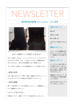
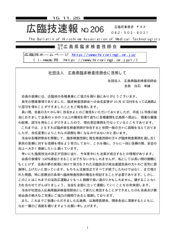
R
デザインプッシュラッチ DPL-RO型/DPL-OV型/DPL-SQ型
PAT.P 取扱説明書
このたびは弊社製品をお買い上げいただき誠にありがとうございます。
取り付け作業に当たっては本書をよくお読みのうえ、正しく取り付けてご使用いただくようお願いいたします。取り付け後は、お使いになる方が本書を保管してください。
部品構成
取付手順
使用方法
側板
17
30
適応扉厚
ケース本体
扉
20
扉を閉めた後、つまみを押し込むとラッチは固定されます。再びつまみをプッ
シュしないかぎり扉は開きません。
つまみ
38(側板からの寸法)
(2)
4
・つまみを押し込むとフラットになり、扉表面の突起がない為、安全です。
・受座は戸当たり兼用ですので、別に戸当たりを取付ける必要が有りません。
φ19
15∼25(扉厚)
製品の機能、特長
図2 取付図
※7 (扉裏面からの寸法)
・ケース(つまみ)本体:1個 ・固定ねじA:十字穴付バインドタッピンねじ(呼び4×20)
:2本
・ラッチ本体:1個
・取付ねじB:十字穴付なべタッピンねじ(呼び3×14):5本
・受座:1個
・取扱説明書:1部
ラッチ本体
15mm∼25mm
使用中の調整、メンテナンス
固定ねじA
受座
・長期間の使用で扉が反ったり、垂れ下がったりすると正常に作動しなくなるこ
とがありますが、その場合は扉の建て付けを調整してください。
・収納物が扉やラッチ本体に当たっていないか確認してください。
・ごみなどがラッチ本体内部に入ると誤作動することがありますので点検してください。
側板
16
23
R6
25
φ28
23
17
12
(2)
8
取付ねじB
15∼25(扉厚)
扉
32
38(側板からの寸法)
図1 取付穴加工図
取付ねじB
本図はDPL-RO型を示します
扉の指定位置に穴加工します。
(図1、図2参照)
扉表面からケース(つまみ)本体を差
し込み、扉裏面より、ラッチ本体の向
きを合わせてはめ込みます。付属の固
定ねじA(十字穴付バインドタッピン
ねじ呼び4×20)で締め付けます。
さらに付属の取付ねじB(十字穴付な
べタッピンねじ呼び3×14 2本)で
扉に固定します。
注意
・固定ねじAはガタつかない程度に締め
付けてください。強く締め付けると破
損の原因となります。
・固定ねじAは付属品をご使用ください。
付属以外のねじを使用すると破損の原
因となります。
受座を取付けます。(図2参照) 付属の取付ねじB(十字穴付なべタッ
ピンねじ呼び3×14 3本)で側板に
取り付けます。
図2※寸法はインセット扉、アウト セット扉共に扉裏面からの寸法です。
注意
・本品は必ず扉を閉じてからつまみを押
し込んでください。つまみを押し込ん
でから扉を閉じると破損の原因となり
ますので、お止めください。
・本品を分解しないでください。正常に
作動しなくなるばかりか、ケガをする
恐れがあります。
本製品に関するご質問・ご相談は、お買い求めいただいた販売店、または下記の窓口にお願いいたします。
電 話 番 号 0 3( 3 864 )1122
月∼金 9:00∼17:30 (年末・年始・夏季休暇等は除く)
アーキテクトサポート室
受付時間
F A X 03( 3863 )6875
E-mail : [email protected]
東京都千代田区岩本町2-5-10 〒101-0032
建 築 金 物・家 具 金 物・機 構 部 品
ISO 9001(JSAQ384)・ISO14001(JSAE597)審査登録
※ISO9001:国内各拠点 ※ISO14001:千葉事業部 千葉工場 および 物流事業部 物流センター
ホームページ http://www.sugatsune.co.jp/
新製 品 の 情報 、会社情 報など最 新 情報を提 供しております。
2009.12 PRINTED IN JAPAN 0467-1
R
Design push knob DPL-RO/DPL-OV/DPL-SQ
PAT.P
Installation manual
Please read this manual and follow the instructions carefully for best result for your installation
38(Distance from sideboard)
φ19
17
Push knob
Knob body
Door
30
Side
board
Screws“A”
Fig.1 Cutout dimensions
Side
board
Door
Attach the counter plate in the designated position (Fig.2)
on the sideboard, using 3 screws “B”.
Note: In FIG. 2, dimensions marked by※ are lengths from
the backside of the door, regardless whether it is an inset
door and overlay application
16
32
23
17
23
R6
15∼25(Door
thickness)
25
φ28
8
12
(2)
Screws“B”
Cautions
・ Tighten assembly screws “A” enough to have a secured
Latch body
Counter plate
38(Distance from sideboard)
Insert the knob body into the hole from the front of the door.
Match the position of the latch body to that of the knob body
at the back of the door and assemble using the 2 screws “A”.
Fix the latch body to the door by using 2 screws “B”.
assembly.
・ Do not over tighten assemble screws “A” as it may damage
the latch body.
・Do not use any assembly screws other than the provided
screws “A” as it may damage the latch body.
4
(2)
20
15mm∼25mm
Drill a φ28mm hole in the door. (See FIG. 1, FIG. 2)
15∼25(Door thickness)
Applicable door thickness
Installation procedure
Fig.2 Installation drawing
※7 (Distance from door backside)
Parts list
・Knob body: 1
・Latch body: 1
・Counter plate: 1
・Screws “A” for push knob and latch body assembly
(cross recessed binding head tapping screw 4x20): 2
・Screws “B” for counter plate and latch body installation
(cross recessed pan head tapping screw 3x14): 5
・ Installation manual: 1 (this manual)
Cautions
・Never close the door with the push knob in the pushed
(closed) position as it may break the latch.
・ Attempting to disassemble this product as you may result
in injury.
Screws“B”
DPL-RO
© Copyright 2026 Paperzz