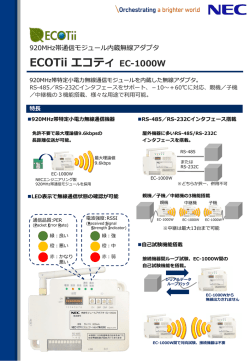
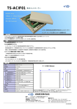
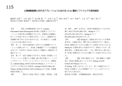
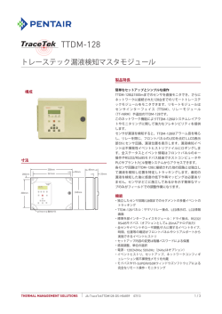
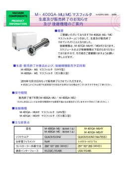
HL-14041-3 取 扱 説 明 書 お買い上げいただきありがとうございます。 電動アクチュエータ用ドライバ 位置決め機能内蔵タイプ DC 電源入力 • 適用規格 はじめに • 製品の取り扱いは、電気・機械工学の専門知識を持つ有資格者 が行なってください。別冊の「お使いになる前に」をよくお読みの うえ、正しくお使いください。 この製品は、一般的な産業機器の機器組み込み用として設計・ 製造されています。その他の用途には使用しないでください。こ の警告を無視した結果生じた損害の補償については、当社は一 切その責任を負いませんので、あらかじめご了承ください。 • LSD-KD は、DGⅡシリーズと EAS シリーズに共通するドライバで す。 EMI Emission Tests EN 61000-6-4 Radiated Emission Test EN 61800-3 C3 EN 55011 group 1 class A EMS Immunity Tests EN 61000-6-2 EN 61800-3 C3 Radiation Field Immunity Test IEC 61000-4-3 Electrostatic Discharge Immunity Test IEC 61000-4-2 Fast Transient / Burst Immunity Test Conductive Noise Immunity Test 取扱説明書の構成 電動アクチュエータ用ドライバ DC 電源入力 FLEX 位置決め機 能内蔵タイプに関する取扱説明書には、次のものがあります。 取扱説明書をよくお読みになってからお使いください。 お使いになる前に DGⅡシリーズ アクチュエータ編 取扱説明書 EAS シリーズ 取扱説明書 EAS シリーズ 製品の確認 電動アクチュエータ用ドライバ DC 電源入力 FLEX 位置決め機能内 蔵タイプ LSD-KD 取扱説明書 (本書) AR シリーズ FLEX DC 電源入力 位置決め機能内蔵タイプ ∗ ユーザーズマニュアル • 取扱説明書をよくお読みになり、製品を安全にお使いください。 • お読みになったあとは、いつでも見られるところに必ず保管してください。 LSD-KD 取扱説明書名 この取扱説明書には、製品の取り扱いかたや安全上の注意事項を示し ています。 EAS シリーズ 製品に添付 DGⅡ シリーズ − − 製品に添付 製品に添付 製品に添付 − − 製品に添付 製品に添付 ダウンロード ダウンロード ∗ ユーザーズマニュアルは AR シリーズと共用になります。 製品には添付していません。詳細は支店・営業所にお問合せいただくか、 当社のホームページからダウンロードしてください。 http://www.orientalmotor.co.jp/ CE マーキング • 低電圧指令 この製品は入力電源電圧が DC24 V のため、低電圧指令の対象外 となりますが、製品の設置・接続を次のように行なってください。 • この製品は、機器組み込み用です。必ず筐体内に設置してくだ さい。 • ドライバの電源は、一次側と二次側が強化絶縁された直流電源 を使用してください。 • EMC 指令 この製品は、ユーザーズマニュアルの「設置・配線例」で、EMC 測 定を行なっています。最終的な機械装置の EMC への適合性は、ア クチュエータ・ドライバと一緒に使用される他の制御システム機器、 電気部品の構成、配線、配置状態などによって変わってきますの で、お客様ご自身で機械装置の EMC 試験を行なって確認してい ただく必要があります。 IEC 61000-4-4 IEC 61000-4-6 • 機械指令(EAS シリーズのみ) 電動アクチュエータとドライバは、一般的な産業機器組み込み用と して設計・製造しており、機械指令に基づいた組み込み宣言 (Declaration of incorporation of partly completed machinery)を実 施しています。 適用規格:EN ISO 12100 騒音レベル:72 dB 有害物質 RoHS(EU 指令 2002/95/EC 27Jan.2003)適合 使用上のお願い 製品をお使いいただくうえでの制限やお願いについて説明します。 • 電源投入時のモーター励磁 この製品は、電源投入時にモーターが励磁します。電源投入時に モーターを無励磁にしたいときは、C-ON 入力を入力端子(IN0~ IN7)に割り当てて制御してください。 • ノイズ対策 ノイズ対策については、ユーザーズマニュアルをご覧ください。 • NV メモリへのデータ保存 データを NV メモリに書き込んでいる間、および書き込み後 5 秒以 内は、電源を切らないでください。書き込みが正常に終了せず、 EEPROM エラーのアラームが発生する原因になります。 NV メモリの書き換え可能回数は、約 10 万回です。 • 回生による過電圧保護アラーム アクチュエータの駆動条件によっては、過電圧保護のアラームが検 出されることがあります。過電圧保護のアラームが検出されたときは、 駆動条件を見直してください。 • DGⅡシリーズでは押し当て運転を行なわないでください モーターやギヤ部が破損するおそれがあります。 1 • EAS4(ボールねじリードピッチ 12 mm)で垂直上向きの押 し当て原点復帰運転を行なう場合、負荷質量を 4 kg 未満に してください 負荷質量が 4 kg 以上になると、機械的ストッパ位置まで押し切れず 原点復帰の停止精度にばらつきが発生します。 名 称 • POWER(緑):主電源が投入されているとき に点灯します。 POWER/ALARM LED • ALARM(赤):アラーム(保護機能)が発生す ると点滅します。点滅回数を数えると、発生し たアラームを確認できます。 準 備 • C-DAT(緑):RS-485 通信によるマスタ局と 製品の確認 C-DAT/C-ERR LED • ドライバ ........................................................................... 1 台 • CN1 用コネクタ(電源入力端子用:5 ピン).................... 1 個 の通信に異常が発生すると点灯します。 RS-485 通信で制御するときに使用してくださ 号機設定スイッチ (SW1) • CN5 用コネクタ(センサ信号用:5 ピン)......................... 1 個 • CN8 用コネクタ(入力信号用:9 ピン)............................ 1 個 • CN9 用コネクタ(出力信号用:7 ピン)............................ 1 個 • 電動アクチュエータ用ドライバ 取扱説明書(本書)...... 1 部 通信速度設定スイッチ (SW2) • • • • アクチュエータ品名 DGM60-AR K EAS4 EAS4 EAS6 EAS6 ユニット品名 - -KD- M-KD- -KD- M-KD- 機番号を設定します。 機能設定スイッチ (SW3) ドライバ品名 LSD-KD す。(出荷時設定:OFF) 主電源入力端子 MB1:電磁ブレーキ-(黒) MB2:電磁ブレーキ+(白) ドライバの主電源を接続します。 (CN1) 地してください。 モーターコネクタ (CN2) アクチュエータを接続します。 データ設定器コネクタ MEXE02 をインストールしたパソコン、または (CN3) OPX-2A を接続します。 バッテリコネクタ オプション(別売)のバッテリ BAT01B を接続し (CN4) ます。 C-DAT/C-ERR LED ภᯏ⸳ቯ䉴䉟䉾䉼䋨SW1䋩 センサ信号コネクタ (CN5) リミットセンサを接続します。 ㅢାㅦᐲ⸳ቯ䉴䉟䉾䉼 䋨SW2䋩 RS-485 通信コネクタ ജାภ䉮䊈䉪䉺䋨CN9䋩 (CN6/CN7) 入力信号コネクタ (CN8) ജାภ䉮䊈䉪䉺䋨CN8䋩 CN1 㔚⏛䊑䊧䊷䉨ធ⛯┵ሶ 䉶䊮䉰ାภ䉮䊈䉪䉺䋨CN5䋩 䊐䊧䊷䊛䉫䊤䊮䊄┵ሶ DIN䊧䊋䊷 2 (CN1-MB1/MB2) す(EAS シリーズのみ)。 AWG24~16(0.2~1.25 mm )の接地線で接 䊝䊷䉺䊷䉮䊈䉪䉺䋨CN2䋩 ਥ㔚Ḯജ┵ሶ 電磁ブレーキ用ケーブルのリード線を接続しま フレームグランド端子 ᯏ⢻⸳ቯ䉴䉟䉾䉼䋨SW3䋩 䊋䉾䊁䊥䉮䊈䉪䉺䋨CN4䋩 No.4: RS-485 通信の終端抵抗(120 Ω)を設 定します。(出荷時設定:OFF) +:+DC24 V 電源 -:電源 GND RS-485ㅢା䉮䊈䉪䉺㩷 䋨CN6/CN7䋩 䊂䊷䉺⸳ቯེ䉮䊈䉪䉺 䋨CN3䋩 No.2: RS-485 通信のプロトコルを設定しま (CN1) 各部の名称と機能 POWER/ALARM LED (出荷時設定:OFF) No.3: 使用しません。 電磁ブレーキ 接続端子 アクチュエータ品名 EASM4 K EASM4 MK EASM6 K EASM6 MK い。RS-485 通信の通信速度を設定します。 (出荷時設定:7) No.1: 号機設定スイッチ(SW1)と併用して、号 ドライバ品名 LSD-KD • EAS シリーズ RS-485 通信で制御するときに使用してくださ い。 • DGⅡシリーズ ユニット品名 DG60-AR KD- い。機能設定スイッチ(SW3)の No.1 と併用し て、RS-485 通信の号機番号を設定します。 (出荷時設定:0) RS-485 通信で制御するときに使用してくださ アクチュエータとドライバの組み合わせ には A(片軸)または B(両軸)が入ります。 にはテーブルタイプ(X、Y)が入ります。 には D(リード 12 mm)または E(リード 6 mm)が入ります。 にはストロークが入ります(ストローク 50 mm は 005)。 には付属ケーブルの長さを表わす数字が入ります。 の通信が正常に行なわれているときに点滅 または点灯します。 • C-ERR(赤):RS-485 通信によるマスタ局と 次のものがすべて揃っていることを確認してください。不足したり破 損している場合は、お買い求めの支店・営業所までご連絡ください。 • 機 能 2 RS-485 通信ケーブルを接続します。 入力信号を接続します。 出力信号コネクタ (CN9) 出力信号を接続します。 DIN レバー ドライバを DIN レールに取り付けます。 DIN レールから取り外すとき 設 置 設置場所 ドライバは、機器組み込み用に設計、製造されています。 風通しがよく、点検が容易な次のような場所に設置してください。 マイナスドライバなどで DIN レバーを引き下げ てロックし、ドライバを下から持ち上げて取り外 します。DIN レバーを引き下げるときは、10~ 20 N 程度の力を加えてください。力を加えすぎ ると、DIN レバーが破損します。 • 屋内に設置された筐体内(換気口を設けてください) • 使用周囲温度 0~+50 °C(凍結しないこと) 接 続 • 使用周囲湿度 85%以下(結露しないこと) • 爆発性雰囲気、有害なガス(硫化ガスなど)、および液体のないと • • • • • • • • ころ 直射日光が当たらないところ 塵埃や鉄粉などの少ないところ 水(雨や水滴)、油(油滴)、およびその他の液体がかからないと ころ 塩分の少ないところ 連続的な振動や過度の衝撃が加わらないところ 電磁ノイズ(溶接機、動力機器など)が少ないところ 放射性物質や磁場がなく、真空でないところ 海抜 1000 m 以下 接続例 CN6/CN7䋺㩷 RS-485ㅢା䉬䊷䊑䊦 CN3䋺OPX-2A 䉁䈢䈲MEXE02 *2 䊝䊷䉺䊷䉬䊷䊑䊦 CN2 䊝䊷䉺䊷↪䉬䊷䊑䊦 CN1䋺⋥ᵹ㔚Ḯ 設置方法 · · · · · CN8䋺 ജାภ CN5䋺 䉶䊮䉰ജ GND 35 mm FG 100 mm ᭂᕈ䈮 䈗ᵈᗧ䈒䈣䈘䈇 +DC24 V GND 50 mmએ • ドライバは汚損度 2 または IP54 以上の筐体内に設置して ください。 • ドライバの周囲には、発熱量やノイズが大きい機器を設置 しないでください。 • ドライバは、コントローラや他の熱に弱い機器の下側に設 置しないでください。 • ドライバの周囲温度が 50 °C を超えるときは、ファンで冷 却したり、ドライバ間に空間を設けるなど、換気条件を見 直してください。 • ドライバは、必ず垂直(縦位置)に設置してください。 ドライバの DIN レバーを引き下げてロックし、背面にあるフックを DIN レールに掛けて、ドライバを押し込みます。 取り付けた後は、エンドプレートでドライバの両側を固定してくださ い。 ∗1 電源および FG 接続ケーブル:AWG24~16(0.2~1.25 mm2) ∗2 入出力信号接続ケーブル:AWG26~20(0.14~0.5 mm2) 重要 • 接続するときは、ドライバのフロントパネルの表示を確認 し、電源の極性を正しく接続してください。極性を間違えて 接続すると、ドライバが破損する原因になります。 • 電源回路と RS-485 通信回路は絶縁されていないため、 RS-485 通信で複数のドライバを制御する場合に電源の 極性を間違えると、短絡経路が発生して破損する原因に なります。 • アクチュエータとドライバ間を延長するときは、オプション (別売)のモーターケーブルを使用してください。アクチュ エータを可動部分に取り付けるときは、耐屈曲性に優れた 可動ケーブルを使用してください。 電源電流容量 品 名 入力電源電圧 電源電流容量 DC24 V±5% 1.8 A 以上 DG60 䊐䉾䉪 EAS4 EAS6 DIN䊧䊷䊦 CN9䋺 ജାภ +DC24 V±5% ドライバはレール幅 35 mm の DIN レール に取り付けてください。ドライバを 2 台以上 並べて設置するときは、水平方向は密着で きます。垂直方向は 50 mm 以上離してくだ さい。ドライバを 3 台以上密着させて設置 すると、内側のドライバの発熱が高くなりま す。使用頻度の少ないドライバを内側に設 置してください。 重要 *1 + · · · 1.3 A 以上 3.8 A 以上 䉣䊮䊄䊒䊧䊷䊃 DIN䊧䊋䊷 3 • CN8 ピンアサイン CN1 • 接続方法 ピン No. 信号名 内 容∗ 1 IN0 制御入力 0(HOME) 1. リード線の被覆を 7 mm 剥きます。 2 IN1 制御入力 1(START) 2. リード線を CN1 用コネクタに挿入し、マイナスドライバでねじを締 3 IN2 制御入力 2(M0) め付けます。 4 IN3 制御入力 3(M1) 締付トルク:0.22~0.25 N·m 5 IN4 制御入力 4(M2) 6 IN5 制御入力 5(FREE) 7 IN6 制御入力 6(STOP) 8 IN7 制御入力 7(ALM-RST) 9 IN-COM1 3. CN1 用コネクタを CN1 に差し込み、ねじを締め付けます。 締付トルク:0.4 N·m CN1 7 mm 䊥䊷䊄✢ • CN9 ピンアサイン ✦ઃ䊃䊦䉪䋺0.4 N·m • ピンアサイン ピン No. 信号名 1 MB1 電磁ブレーキ-(黒) 2 MB2 電磁ブレーキ+(白) 3 + +DC24 V 電源入力 4 - 電源 GND 5 FG フレームグランド 内 容 1 2 3 4 5 ピン No. 信号名 内 容∗ 1 OUT0 制御出力 0(HOME-P) 2 OUT1 制御出力 1(END) 3 OUT2 制御出力 2(AREA1) 4 OUT3 制御出力 3(READY) 5 OUT4 制御出力 4(WNG) 6 OUT5 制御出力 5(ALM) 7 OUT-COM 出力信号用コモン 1 2 3 4 5 6 7 ∗ ( )内は出荷時に割り付けられている機能です。 CN6、CN7 CN3 • ピンアサイン CN3䈮ធ⛯ ピン No. OPX-2A䈱䉬䊷䊑䊦䉁䈢䈲 䊂䊷䉺⸳ቯ䉸䊐䊃↪ㅢା䉬䊷䊑䊦 ᵈᗧ ドライバの電源コネクタ(CN1)、データ設定器コネクタ (CN3)、および RS-485 通信コネクタ(CN6/CN7)は絶 縁されていません。電源のプラス側を接地するときは、 マイナス側を接地した機器(パソコンなど)を接続しない でください。これらの機器とドライバが短絡して、破損す る原因になります。 CN5、CN8、CN9 • 接続方法 1. リード線の被覆を 8 mm 剥きます。 2. マイナスドライバで橙色のボタンを押したまま、リード線を挿入し ます。 ᯍ⦡䈱䊗䉺䊮 3. リード線を挿入したら、ボタ 8 mm ンを離してリード線を固定 䊥䊷䊄✢ します。 • CN5 ピンアサイン 4 入力信号用コモン ∗ ( )内は出荷時に割り付けられている機能です。 CN1↪䉮䊈䉪䉺 ピン No. 1 2 3 4 5 6 7 8 9 信号名 内 容 1 +LS +側リミットセンサ入力 2 −LS -側リミットセンサ入力 3 HOMES 4 SLIT 5 IN-COM2 機械原点センサ入力 スリットセンサ入力 センサ用コモン 1 2 3 4 5 信号名 内 容 1 N.C. 未使用 2 GND GND 3 TR+ RS-485 通信用信号(+) 4 N.C. 未使用 5 N.C. 未使用 6 TR− RS-485 通信用信号(-) 7 N.C. 未使用 8 N.C. 未使用 1 2 • • • 7 8 通信速度 設 定 No.1䋺ภᯏ⇟ภ䉕⸳ቯ No.2䋺䊒䊨䊃䉮䊦䉕⸳ቯ No.3䋺↪䈚䉁䈞䉖 No.4䋺⚳┵ᛶ᛫䉕⸳ቯ ᯏ⢻⸳ቯ䉴䉟䉾䉼 䋨SW3䋩 ภᯏ⸳ቯ䉴䉟䉾䉼䋨SW1䋩 ㅢାㅦᐲ⸳ቯ䉴䉟䉾䉼䋨SW2䋩 通信速度設定スイッチ(SW2)で通信速度を設定します。 通信速度は、マスタ機器の通信速度と同じ値を設定してください。 出荷時設定 7 SW2 通信速度(bps) SW2 通信速度(bps) 0 9600 4 115,200 1 19200 5、6 使用しません 2 38400 7 ネットワークコンバータ 3 57600 8~F 使用しません 重要 重要 スイッチを設定するときは、必ずドライバの電源を切ってくだ さい。電源が投入されている状態で設定しても、有効になり ません。 プロトコル 機能設定スイッチ(SW3)の No.2 で、RS-485 通信のプロトコルを設 定します。 出荷時設定 OFF SW3-No.2 プロトコル 5、6、および 8~F の目盛りは設定しないでください。 終端抵抗 終端抵抗設定スイッチ(SW3-No.4)を ON にして、RS-485 通信の終 端抵抗(120 Ω)を設定してください。 出荷時設定 OFF SW3-No.4 終端抵抗(120 Ω) OFF なし ON あり 点 検 ON Modbus RTU モード OFF ネットワークコンバータとの接続 号機番号 号機設定スイッチ(SW1)と機能設定スイッチ(SW3)の No.1 を併用 して、号機番号を設定します。号機番号は重複しないように設定し てください。 出荷時設定 SW1:0、SW3-No.1:OFF 運転後は、定期的に次の項目について点検することをおすすめし ます。異常があるときは使用を中止し、お客様ご相談センターにお 問い合わせください。 点検項目 • ドライバの開口部が目詰まりしていないか。 • ドライバの取付ねじや接続部に緩みがないか。 • ドライバに埃などが付着していないか。 SW3-No.1:OFF 時の SW3-No.1:ON 時の 号機番号 号機番号 0 0∗ 16 1 1 17 2 2 18 3 3 19 4 4 20 5 5 21 6 6 22 周囲温度 0~+50 °C(凍結しないこと) 湿 度 85%以下(結露しないこと) 高 度 海抜 1000 m 以下 SW1 7 7 23 8 8 24 9 9 25 A 10 26 B 11 27 C 12 28 D 13 29 E 14 30 F 15 31 • ドライバに異臭や異常がないか。 重要 ドライバには半導体素子が使われています。静電気などに よって半導体素子が破損するおそれがあるため、取り扱い には注意してください。 一般仕様 使用環境 雰囲気 保存環境 輸送環境 腐食性ガス、塵埃のないこと。 水、油が直接かからないこと。 周囲温度 −25~+70 °C(凍結しないこと) 湿 度 85%以下(結露しないこと) 高 度 雰囲気 ∗ Modbus プロトコルの場合、号機番号 0 はブロードキャストで予約されてい るので、使用しないでください。 IP10 保護等級 海抜 3000 m 以下 腐食性ガス、塵埃のないこと。 水、油が直接かからないこと。 周囲温度 −25~+70 °C(凍結しないこと) 湿 度 85%以下(結露しないこと) 高 度 海抜 3000 m 以下 雰囲気 腐食性ガス、塵埃のないこと。 水、油が直接かからないこと。 5 パラメータ設定 LSD-KD は、DGⅡシリーズと EAS シリーズに共通しているため、パラメータが最適な値に設定されていません。 製品を使いやすくするために、次の設定例と換算式を参考にしてパラメータを設定してください。 DGⅡシリーズ 最小移動量を 0.01 °に設定した場合のパラメータ設定例を紹介します。 は変更するパラメータを表わします。 設定項目 設定例 1 回転の移動量[°] 分解能(最小移動量[°]) 360 360 18000(0.02) 18 18 1 1 電子ギヤ A 電子ギヤ B モーター回転方向 ∗ 36000(0.01) 減速比 座 標 初期値 2 1 +側=CCW (出力テーブルは CW 方向へ回転) +側=CW (出力テーブルは CCW 方向へ回転) ∗ 工場出荷時、およびデータ初期化時の値です。 換算式 ᦨዊ⒖േ㊂䌛°䌝㩷= 360° ᷫㅦᲧ㩷× 1000 × 䋨㔚ሶ䉩䊟B䋯㔚ሶ䉩䊟A 䋩 EAS シリーズ 最小移動量を 0.01 mm に設定した場合のパラメータ設定例を紹介します。 は変更するパラメータを表わします。 • ボールねじリード:6 mm 設定例 設定項目 換算値 設定値 6 − 6 − 600(0.01) − 1000(0.006) − 電子ギヤ A 5 − 1 − 電子ギヤ B 3 − 1 − 分解能(最小移動量[mm]) +側=CW モーター回転方向 運転 データ (反モータ側へ移動) +側=CW − (反モータ側へ移動) 1000 10[mm] 0 0[mm] 10000 100[mm/s] 1000 6[mm/s] 1000 10[m/s ] 1000 6[m/s ] 10000 100[mm/s] 1000 6[mm/s] 1000 10[m/s ] 1000 6[m/s ] 3[mm/s] 加速(減速)レート[ms/kHz] (設定値 1:0.001 ms/kHz) JOG 加速(減速)レート[ms/kHz] (設定値 1:0.001 ms/kHz) 原点復帰オフセット 2 2 2 600 6[mm/s] 500 − 3 センサ − 600 6[mm/s] 500 3[mm/s] EAS4 0 0[mm] 0 0[mm] EAS6 300 3[mm] 0 0[mm] 原点復帰起動速度[Hz] 原点復帰 [step] 2 押し当て JOG 起動速度[Hz] -側 +側 − 原点復帰開始方向 (モーター側に向かって 原点復帰開始) − +ソフトウェアリミット[step] (ストローク×100)+300 ストローク+3[mm] 8388607 50331.642[mm] -ソフトウェアリミット[step] −200 −2[mm] −8388608 −50331.648[mm] ∗ 工場出荷時、およびデータ初期化時の値です。 6 − 運転速度[Hz] 原点復帰方法 座 標 換算値 位置[step] JOG 運転速度[Hz] 運 転 ∗ 設定値 リード[mm] 座 標 初期値 (反モーター側に向 かって原点復帰開始) • ボールねじリード:12 mm 設定例 設定項目 換算値 設定値 換算値 12 − 12 − 1200(0.01) − 1000(0.012) − 電子ギヤ A 5 − 1 − 電子ギヤ B 6 − 1 − 分解能(最小移動量[mm]) +側=CW モーター回転方向 運転 データ +側=CW − (反モータ側へ移動) (反モータ側へ移動) 1000 10[mm] 0 0[mm] 運転速度[Hz] 10000 100[mm/s] 1000 12[mm/s] JOG 運転速度[Hz] 1000 12[m/s ] 10000 100[mm/s] 1000 12[mm/s] 2 2 1000 10[m/s ] 1000 12[m/s ] 600 6[mm/s] 500 6[mm/s] 押し当て − 3 センサ − 600 6[mm/s] 500 6[mm/s] EAS4 0 0[mm] 0 0[mm] EAS6 300 3[mm] 0 0[mm] (設定値 1:0.001 ms/kHz) JOG 起動速度[Hz] 原点復帰方法 原点復帰起動速度[Hz] 原点復帰オフセット 2 10[m/s ] JOG 加速(減速)レート[ms/kHz] 原点復帰 [step] 2 1000 (設定値 1:0.001 ms/kHz) -側 座 標 − 位置[step] 加速(減速)レート[ms/kHz] 運 転 ∗ 設定値 リード[mm] 座 標 初期値 +側 原点復帰開始方向 (モーター側に向かって 原点復帰開始) − (反モーター側に向 かって原点復帰開始) − +ソフトウェアリミット[step] (ストローク×100)+300 ストローク+3[mm] 8388607 100663.284[mm] -ソフトウェアリミット[step] −200 −2[mm] −8388608 −100663.296[mm] ∗ 工場出荷時、およびデータ初期化時の値です。 重要 • EAS4 で垂直上向きの押し当て原点復帰運転を行なう場合、負荷質量を 4 kg 未満にしてください。 負荷質量が 4 kg 以上になると、機械的ストッパ位置まで押し切れず原点復帰の停止精度にばらつきが発生します。 • 押し当て原点復帰オフセットの設定量は、次の値より大きくしてださい。初期値のままで押し当て原点復帰を行なうと、テーブ ルがゴムストッパに当たった状態になり、原点復帰精度に悪影響があります。 ・EAS4 は 2 mm(設定値:0 メカ端から 200 step 移動)以上 ・EAS6 は 5 mm(設定値:300 メカ端から 500 step 移動)以上 • 換算式 ᦨዊ⒖േ㊂䌛mm䌝= 䊥䊷䊄䌛mm䌝 1000 × 䋨㔚ሶ䉩䊟B䋯㔚ሶ䉩䊟A䋩 ⟎㪲mm㪴∗1㩷= ⟎㪲step㪴㩷× ᦨዊ⒖േ㊂㪲mm㪴 ㅦᐲ䌛mm/s䌝∗2∗3∗4㩷= ㅦᐲ㪲Hz㪴㩷× ᦨዊ⒖േ㊂㪲mm㪴 ടᷫㅦᐲ䌛m/s2䌝∗5㩷= ᦨዊ⒖േ㊂䌛mm䌝㩷× 1000 × 1000 ടᷫㅦ䊧䊷䊃䌛ms/kHz䌝 ේὐᓳᏫ䉥䊐䉶䉾䊃䌛mm䌝㩷= ේὐᓳᏫ䉥䊐䉶䉾䊃䌛step䌝 × ᦨዊ⒖േ㊂䌛mm䌝 ∗1 位置はお使いのアクチュエータのストロークの範囲内で設定してください。 ∗2 運転速度は各アクチュエータの最大速度の仕様値を確認して設定してください。 ∗3 テスト運転の JOG 運転速度は 250 mm/s 以下に設定してください。 ∗4 起動速度は 6 mm/s 以下に設定してください。 ∗5 加減速度は各アクチュエータの最大加減速度の仕様値を確認して設定してください。 7 • この取扱説明書の一部または全部を無断で転載、複製するこ とは、禁止されています。 • 取扱説明書に記載されている情報、回路、機器、および装置 の利用に関して産業財産権上の問題が生じても、当社は一切 の責任を負いません。 • 製品の性能、仕様および外観は改良のため予告なく変更する ことがありますのでご了承ください。 • 取扱説明書には正確な情報を記載するよう努めていますが、 万一ご不審な点や誤り、記載もれなどにお気づきの点がありま したら、最寄りのお客様ご相談センターまでご連絡ください。 • と は、日本その他の国におけるオリ エンタルモーター株式会社の登録商標または商標です。 © Copyright ORIENTAL MOTOR CO., LTD. 2012 http://www.orientalmotor.co.jp/ ȝץնȮሻՠˁᜪץɿ˂ʝʃɁȧಘюᴥଆ࢛ᝈˁÐÈÓȞɜɕȧҟႊժᑤȺȬᴦ • ᛏֿȾᩜȬɞȝᝈȺɁ੫ᚓᄑȽȧᄾᝬ ᴥᣮᝈ୳ི୳ᴦ ȝറȧᄾᝬʅʽʉ˂ • းکȺɁץᭉᜓขȾɿ˂ʝʃ ɲʽʂʕɬɁᜪץɥȧఖɁ کնᴥི୳ᴦ FAX 0120-925-601 ʟɭ˂ʵʓɿ˂ʝʃ ూ ̱ TEL 0120-925-410 ջաࠎ TEL 0120-925-420 FAX 0120-925-602 ۾ ᩸ TEL 0120-925-430 FAX 0120-925-603 ՙ͇ᩖ ࢲஓ 8:00ᵻ20:00 ٠௷ஓ 9:00ᵻ17:30 8 TEL 0120-911-271 ՙ͇ᩖ ࢲஓ 9:00ᵻ18:30 HL-14041-3 OPERATING MANUAL Thank you for purchasing an Oriental Motor product. Motorized Actuator Driver Built-in controller type DC power input This Operating Manual describes product handling procedures and safety precautions. LSD-KD • Always keep the manual where it is readily available. • EMC Directive Introduction • Only qualified personnel should work with the product. Use the product correctly after thoroughly reading the separate manual BEFORE USING THE PRODUCT. The product described in this manual has been designed and manufactured for use in general industrial equipment. Do not use for any other purpose. Oriental Motor Co., Ltd. is not responsible for any damage caused through failure to observe this warning. • The driver model LSD-KD is a driver common to the DGⅡ Series and EAS Series. This product has received EMC compliance under the conditions specified in "Example of actuator and driver installation and wiring" on USER MANUAL. Since the compliance with the EMC Directive of the customer's equipment will be affected by various conditions such as the configuration, wiring and layout of the control system devices and electrical parts used together with the actuator and driver, the customer finally must verify the conformance of the equipment by performing EMC Testing. • Applicable Standards EMI Operating manual types Operating manuals for the Motorized Actuator Driver DC power input FLEX Built-in controller type are listed below. Use the product correctly after thoroughly reading the operating manuals. Operating Manual name • Please read it thoroughly to ensure safe operation. EAS Series DGⅡ Series Emission Tests EN 61000-6-4 Radiated Emission Test EN 61800-3 C3 EN 55011 group 1 class A EMS Immunity Tests EN 61000-6-2 EN 61800-3 C3 Supplied with the product − − Supplied with the product EAS Series OPERATING MANUAL Supplied with the product − • Machinery Directive (EAS Series only) EAS Series CHECKING THE PRODUCT Supplied with the product − Supplied with the product Supplied with the product The motorized actuators and drivers have been designed and manufactured to be installed within general industrial equipment, and a Declaration of Incorporation of Partly Completed Machinery is issued with them according to the Machinery Directive. Applicable standards: EN ISO 12100 Noise level: 72 dB BEFORE USING THE PRODUCT DGⅡSeries Actuator Edition OPERATING MANUAL Motorized Actuator Driver DC power input FLEX Built-in controller type LSD-KD OPERATING MANUAL (this document) AR Series FLEX DC power input Built-in Controller Type − − ∗ USER MANUAL ∗ The USER MANUAL for this product is in common with the AR Series. This manual does not come with the product. For details, contact your nearest Oriental Motor sales office. CE Marking Radiation Field Immunity Test IEC 61000-4-3 Electrostatic Discharge Immunity Test IEC 61000-4-2 Fast Transient / Burst Immunity Test Conductive Noise Immunity Test IEC 61000-4-4 IEC 61000-4-6 Hazardous substances RoHS (Directive 2002/95/EC 27Jan.2003) compliant Precautions for use This section covers limitations and requirements the user should consider when using the product. • Low Voltage Directives • Motor excitation at power ON Because the input power supply voltage of this product is 24 VDC, it is not subject to the Low Voltage Directive but install and connect this product as follows. • This product is designed and manufactured to be installed within another device. Install the product in an enclosure. • For the driver power supply, use a DC power supply with reinforced insulation on its primary and secondary sides. The motor used in this product is excited when the power is turned on. If the motor is required to be in non-excitation state when turning on the power, assign the C-ON input to the input terminal (IN0 to IN7). • Preventing electrical noise Refer to USER MANUAL for the noise elimination measures. 1 • Saving data to the non-volatile memory Names and functions of parts Do not turn off the power supply while writing the data to the non-volatile memory, and also do not turn off at least for 5 seconds after writing the data. Doing so may abort writing the data and cause an EEPROM error alarm to generate. The non-volatile memory can be rewritten approximately 100,000 times. RS-485 communication connectors (CN6/CN7) Function setting switches (SW3) • Overvoltage alarm by regeneration energy The overvoltage alarm will generate depending on the operating condition. When an alarm is generated, review the operating conditions. • Do not perform push-motion operation with the DGⅡ Series. Doing so may result in damage to the motor or gear part. • When performing sensorless return-to-home operation upward in a vertical direction with the EAS4 type (ball screw lead 12 mm), keep the load mass to be less than 4 kg. If the load mass is 4 kg or more, the actuator cannot push up to the position of the mechanical stopper, causing irregularity in the stopping accuracy of return-to-home. Preparation POWER/ALARM LED Data edit connector (CN3) Battery connector (CN4) Input signal connector (CN8) CN1 Electromagnetic brake terminals • Driver.............................................................................. 1 unit • CN1 connector (for power supply input terminals; 5 pins) ...................... 1 pc. • CN5 connector (for sensor signals; 5 pins) ..................... 1 pc. • CN8 connector (for input signals; 9 pins) ....................... 1 pc. • CN9 connector (for output signals; 7 pins) ..................... 1 pc. • Motorized Actuator Driver OPERATING MANUAL (this document)...................... 1 copy DIN lever Name POWER/ ALARM LED C-DAT/C-ERR LED Combinations of actuators and drivers • indicates A (single shaft) or B (double shaft). • indicates the table type (X or Y). • indicates D (ball screw lead: 12 mm) or E (ball screw lead: 6 mm). • indicates the stroke (If the stroke is 50 mm, enter 005). • indicates the supplied cable length. • DGⅡ Series DG60-AR KD- Actuator model Driver model DGM60-AR K LSD-KD Address number setting switch (SW1) Transmission rate setting switch (SW2) • EAS Series Model Actuator model EAS4 - -KD- EASM4 K EAS4 - M-KD- EASM4 MK EAS6 - -KD- EASM6 K EAS6 - M-KD- EASM6 MK 2 Sensor signal connector (CN5) Frame Ground Terminal Verify that the items listed below are included. Report any missing or damaged items to the branch or sales office from which you purchased the product. Model Output signal connector (CN9) Motor connector (CN2) Power supply input terminals Checking the product C-DAT/C-ERR LED Address number setting switch (SW1) Transmission rate setting switch (SW2) Driver model LSD-KD Function setting switches (SW3) Description • POWER (Green): This LED is lit while the main power is input. • ALARM (Red): This LED will blink when an alarm generates. It is possible to check the generated alarm by counting the number of times the LED blinks. • C-DAT (Green): This LED will blink or illuminate steadily when the driver is communicating with the master station properly via RS-485 communication. • C-ERR (Red): This LED will illuminate when a RS-485 communication error occurs with the master station. Use this switch when controlling the system via RS-485 communication. Using this switch in combination with the SW3-No.1 of the function setting switch, the address number (slave address) of RS-485 communication can be set. (Factory setting: 0) Use this switch when controlling the system via RS-485 communication. Set the transmission rate of RS-485 communication. (Factory setting: 7) Use this switch when controlling the system via RS-485 communication. No.1: Using this switch in combination with the address number setting switch (SW1), the address number (slave address) of RS-485 communication can be set. (Factory setting: OFF) No.2: The transmission rate of RS-485 communication can be set. (Factory setting: OFF) No.3: Not used. No.4: Set the termination resistor (120 Ω) of RS-485 communication. (Factory setting: OFF) Name Electromagnetic brake terminals (CN1-MB1/MB2) Power supply input terminals (CN1) Frame Ground Terminal (CN1) Motor connector (CN2) Data edit connector (CN3) Battery connector (CN4) Sensor signal connector (CN5) RS-485 communication connectors (CN6/CN7) Input signal connector (CN8) Output signal connector (CN9) DIN lever Description Connects the lead wires of "cable for electromagnetic brake" (for the EAS Series only). MB1: Electromagnetic brake − (black) MB2: Electromagnetic brake + (white) Connects a main power supply of the driver. +: +24 VDC/48 VDC power supply input −: power supply GND Ground using a wire of AWG24 to 16 (0.2 2 to 1.25 mm ). Connects the actuator. Connects a PC in which the MEXE02 has been installed, or the OPX-2A. Connects an accessory battery BAT01B (sold separately). Note • Install the driver in an enclosure whose pollution degree is 2 or better environment, or whose degree of protection is IP54 minimum. • Do not install any equipment that generates a large amount of heat or noise near the driver. • Do not install the driver underneath the controller or other equipment vulnerable to heat. • If the ambient temperature of the driver exceeds 50 °C (122 °F), improve the ventilation condition such as providing forced cooling by using fans or creating spaces between the drivers. • Be sure to install the driver vertically (vertical position). Pull down the driver’s DIN lever and lock it. Hang the hook at the rear to the DIN rail, and push in the driver. After installation, secure the both sides of the driver with the end plate. Connects the limit sensor. Connects the RS-485 communication cable. Hook Connects the input signals. DIN rail 㪜㫅㪻㩷㫇㫃㪸㫋㪼 Connects the output signals. DIN lever Installs the driver to DIN rail. Removing from DIN rail Installation Location for installation The driver has been designed and manufactured to be installed within another device. Install them in a well-ventilated location that provides easy access for inspection. The location must also satisfy the following conditions: • Inside an enclosure that is installed indoors (provide vent holes) • Operating ambient temperature 0 to +50 °C (+32 to +122 °F) (non-freezing) • Operating ambient humidity 85% or less (non-condensing) • Area that is free of explosive atmosphere or toxic gas (such as sulfuric gas) or liquid • Area not exposed to direct sun • Area free of excessive amount of dust, iron particles or the like • Area not subject to splashing water (rain, water droplets), oil (oil droplets) or other liquids • Area free of excessive salt • Area not subject to continuous vibration or excessive shocks • Area free of excessive electromagnetic noise (from welders, power machinery, etc.) • Area free of radioactive materials, magnetic fields or vacuum • 1000 m (3300 ft.) or lower above sea level Installation method Connection Connection example CN6/7: RS-485 Communication cable CN3䋺OPX-2A or MEXE02 ∗2 CN2 Motor cable Cable for motor CN1: DC power input ∗1 + • • • CN9: Output signals • • • • • CN8: Input signals CN5: Sensor inputs +24 VDC±5% GND FG Pay attention to the polarity of the power supply. 35 (1.38) 100 (3.94) 50 (1.97) or more Mount the driver to a 35 mm (1.38 in.) width DIN rail. When installing two or more drivers in parallel, it is possible to install them closely in the horizontal direction.Provide a minimum clearance of 50 mm (1.97 in.) in the vertical direction.When installing three or more drivers closely, the heat generation of the inside drivers become high. Install the less frequently used drivers toward the inside. Pull the DIN lever down until it locks using a flat tip screwdriver, and lift the bottom of the driver to remove it from the rail. Use force of about 10 to 20 N (2.2 to 4.5 lb.) to pull the DIN lever to lock it. Excessive force may damage the DIN lever. +24 VDC GND ∗1 Power supply and FG connection cable: AWG24 to 16 (1.25to 0.2 mm2) ∗2 I/O signals connection cable: AWG26 to 20 (0.5to 0.14 mm2) [Unit: mm (in.)] 3 • When connecting, check the indication on the driver front panel and properly connect according to the polarity of the power supply. Reverse-polarity connection may cause damage to the driver. • The power-supply circuit and the RS-485 communication circuit are not insulated. Therefore, when controlling multiple drivers via RS-485 communication, the reverse polarity of the power supply will cause a short circuit and may result in damage to the drivers. • Use an accessory motor cable when extending the wiring distance between the actuator and driver. When installing the actuator to a moving part, use an accessory flexible cable offering excellent flexibility. Note Power supply input voltage DG60 Power supply current capacity 1.3 A or more EAS4 24 VDC±5% EAS6 1.8 A or more 3.8 A or more CN1 1. Strip the insulation cover of the lead wire by 7 mm (0.28 in.) 2. Insert each lead wire into the CN1 connector and tighten the screw using a screwdriver. Tightening torque: 0.22 to 0.25 N·m (31 to 35 oz-in) 3. Insert the CN1 connector into CN1 and tighten the screws. Tightening torque: 0.4 N·m (56 oz-in) 7 mm (0.28 in.) CN1 Lead wire Tightening torque: 0.4 N·m (56 oz-in) Description MB1 Electromagnetic brake− (Black) 2 MB2 Electromagnetic brake+ (White) 3 + +24 VDC/48 VDC power supply input 1 4 - GND 5 FG Frame Ground 1 2 3 4 5 Button of the orange color 3. After having inserted, release the button to secure the lead wire. 8 mm (0.31 in.) Lead wire • CN5 pin assignment Signal name Description 1 +LS +limit sensor input 2 −LS −limit sensor input 3 HOMES Mechanical home sensor input 4 SLIT 5 IN-COM2 1 2 3 4 5 Slit sensor input Sensor signals common • CN8 pin assignment Pin No. Signal name Description ∗ 1 IN0 Input signal 0 (HOME) 2 IN1 Input signal 1 (START) 3 IN2 Input signal 2 (M0) 4 IN3 Input signal 3 (M1) 5 IN4 Input signal 4 (M2) 6 IN5 Input signal 5 (FREE) 7 IN6 Input signal 6 (STOP) 8 IN7 Input signal 7 (ALM-RST) 1 2 3 4 5 6 7 8 9 Pin No. Signal name 1 OUT0 Output signal 0 (HOME-P) 2 OUT1 Output signal 1 (END) 3 OUT2 Output signal 2 (AREA1) 4 OUT3 Output signal 3 (READY) 5 OUT4 Output signal 4 (WNG) 6 OUT5 Output signal 5 (ALM) Description ∗ 1 2 3 4 5 6 7 7 OUT-COM Output signals common ∗ ( ) is a function that is assigned at the time of shipment. CN6, CN7 CN3 • Pin assignments Connect to CN3 Cable for OPX-2A or communication cable for data setting software Caution The power supply connector (CN1), data edit connector (CN3) and RS-485 communication connectors (CN6/CN7) of the driver are not electrically insulated. When grounding the positive terminal of the power supply, do not connect any equipment (PC, etc.) whose negative terminal is grounded. Doing so may cause the driver and these equipment to short, damaging both. 4 with a screwdriver. • CN9 pin assignment • Pin assignment Signal name 1. Strip the insulation cover of the lead wire by 8 mm (0.31 in.) 2. Insert the lead wire while pushing the button of the orange color 9 IN-COM1 Input signals common ∗ ( ) is a function that is assigned at the time of shipment. CN1 connector Pin No. • Connecting method Pin No. Power supply current capacity Motor model CN5, CN8, CN9 Pin No. Signal name Description 1 N.C. Not used 2 GND GND 3 TR+ RS-485 communication signal (+) 4 N.C. Not used 5 N.C. Not used 6 TR− RS-485 communication signal (−) 7 N.C. Not used 8 N.C. Not used 1 2 • • • 7 8 Transmission rate Setting No.1: Set the address number No.2: Set the protocol No.3: Not used. No.4: Set the termination resistor The transmission rate can be set using the transmission rate setting switch (SW2). The transmission rate to be set should be the same as the transmission rate of the master device. Factory setting 7 Address number setting switch (SW1) Transmission rate setting switch (SW2) Be sure to turn off the driver power before setting the switches. If the switches are set while the power is still on, the new switch settings will not become effective until the driver power is cycled. Protocol 9600 4 115,200 1 19200 5、6 Not used 2 38400 7 Network converter 3 57600 8~F Not used Modbus RTU mode OFF Network converter SW3-No.4 Termination resistor (120 Ω) OFF Disabled ON Enabled Inspection Address number The address number (slave address) can be set using the address number setting switch (SW1) in combination with the SW3-No.1 of the function setting switch. Make sure each address number (slave address) you set for each driver is unique. Factory setting SW1: 0, SW3-No.1: OFF SW1 Do not set SW2 to positions 5, 6 and 8 to F. Termination resistor Protocol ON Transmission rate (bps) Turn the SW3-No.4 of the termination resistor setting switch ON to set the termination resistor of RS-485 communication (120 Ω). Factory setting OFF The protocol of RS-485 communication can be set using the SW3-No.2 of the function setting switch. Factory setting OFF SW3-No.2 SW2 0 Note Note Transmission rate (bps) SW2 Function setting switches (SW3) Address number SW3-No.1: OFF SW3-No.1: ON 0 0∗ 16 1 1 17 2 2 18 3 3 19 4 4 20 5 5 21 6 6 22 7 7 23 8 8 24 9 9 25 A 10 26 B 11 27 C 12 28 D 13 29 E 14 30 F 15 31 ∗ When selecting Modbus protocol, do not use the address number (slave address) 0 since it is reserved for broadcasting. It is recommended that periodic inspections be conducted for the items listed below after each operation of the actuator. If an abnormal condition is noted, discontinue any use and contact your nearest Oriental Motor sales office. During inspection • • • • Check for a blocked opening of the driver case. Are any of the driver mounting screws or connection loose? Is there attachment of dust, etc., on the driver? Are there any strange smells or appearances within the driver? Note The driver uses semiconductor elements. Handle the driver with care since static electricity may damage semiconductor elements. Static electricity may damage the driver. General specifications Degree of protection Operation environment Operation environment Shipping environment IP10 Ambient temperature 0 to +50 °C (+32 to +122 °F) (non-freezing) Humidity 85% or less (non-condensing) Altitude Up to 1000 m (3300 ft.) above sea level Surrounding atmosphere No corrosive gas, dust, water or oil Ambient temperature −25 to +70 °C (−13 to +158 °F) (non-freezing) Humidity 85% or less (non-condensing) Altitude Up to 1000 m (3300 ft.) above sea level Surrounding atmosphere No corrosive gas, dust, water or oil Ambient temperature −25 to +70 °C (−13 to +158 °F) (non-freezing) Humidity 85% or less (non-condensing) Altitude Up to 1000 m (3300 ft.) above sea level Surrounding atmosphere No corrosive gas, dust, water or oil 5 Parameter setting example The parameters of the driver LSD-KD are not set properly since the LSD-KD is common to the DGⅡ Series and EAS Series. To use the product properly, set the parameters referring to the following setting examples and conversion formula. DGⅡ Series An example to set the resolution (minimum step angle) to 0.01° is shown below. Represents parameters to be changed. Setting items Step angle per one rotation [°] Resolution (Minimum step angle [°]) 360 360 36000 (0.01) 18000 (0.02) Gear ratio Coordination Initial value∗ Setting example 18 18 Electronic gear A 1 1 Electronic gear B 2 1 Positive direction=CCW (The output table rotates in the CW direction) Positive direction=CW (The output table rotates in the CCW direction) Motor rotation direction ∗ Factory setting data or initialized data. Conversion formula Minimum step angle [°] = 360° Gear ratio × 1000 × (Electronic gear B / Electronic gear A ) EAS Series An example to set the resolution (minimum travel amount) to 0.01 mm is shown below. Represents parameters to be changed. • Ball screw lead: 6 mm Initial value∗ Setting example Setting items Ball screw lead [mm] Resolution (Minimum travel amount [mm]) Electronic gear A Electronic gear B Motor rotation direction Operation Setting value Converted value 6 − 6 − 600 (0.01) − 1000 (0.006) − 5 − 1 − 3 − 1 − − Positive direction=CW (The linear slide table moves to opposite the motor side) − Position [step] 1000 10 [mm] 0 0 [mm] Operating speed [Hz] 10000 100 [mm/s] 1000 6 [mm/s] Acceleration (deceleration) rate [ms/kHz] (Setting value1: 0.001 ms/kHz) 1000 10 [m/s ] 1000 6 [m/s ] JOG operating speed[Hz] 10000 100 [mm/s] 1000 6 [mm/s] JOG acceleration (deceleration) rate [ms/kHz] (Setting value1: 0.001 ms/kHz) 1000 10 [m/s ] 1000 6 [m/s ] JOG starting speed [Hz] 2 2 2 600 6 [mm/s] 500 3 [mm/s] − 3-sensor mode − 600 6 [mm/s] 500 3 [mm/s] EAS4 0 0 [mm] 0 0 [mm] EAS6 300 3 [mm] 0 0 [mm] Starting direction of home-seeking Negative direction (Return-to-home operation starts to the motor side) − Positive direction (Return-to-home operation starts to opposite the motor side) − Positive software limit [step] (Stroke × 100) + 300 Stroke + 3 [mm] 8388607 50331.642 [mm] Negative software limit [step] −200 −2 [mm] −8388608 −50331.648 [mm] Starting speed of home-seeking [Hz] Position offset of home-seeking [step] Coordination ∗ Factory setting data or initialized data. 6 2 Push mode Home-seeking mode Return-tohome Converted value Positive direction=CW (The linear slide table moves to opposite the motor side) Coordination Operation data Setting value • Ball screw lead: 12 mm Initial value∗ Setting example Setting items Setting value Converted value Setting value Converted value 12 − 12 − 1200 (0.01) − 1000 (0.012) − Electronic gear A 5 − 1 − Electronic gear B 6 − 1 − − Positive direction=CW (The linear slide table moves to opposite the motor side) − Ball screw lead [mm] Resolution (Minimum travel amount [mm]) Positive direction=CW (The linear slide table moves to opposite the motor side) Coordination Motor rotation direction Operation data Operation Position [step] 1000 10 [mm] 0 0 [mm] Operating speed [Hz] 10000 100 [mm/s] 1000 12 [mm/s] Acceleration (deceleration) rate [ms/kHz] (Setting value1: 0.001 ms/kHz) 1000 10 [m/s ] 1000 12 [m/s ] JOG operating speed [Hz] 10000 100 [mm/s] 1000 12 [mm/s] JOG acceleration (deceleration) rate [ms/kHz] (Setting value1: 0.001 ms/kHz) 1000 10 [m/s ] 1000 12 [m/s ] JOG starting speed [Hz] 2 2 2 600 6 [mm/s] 500 6 [mm/s] Push mode − 3-sensor mode − 600 6 [mm/s] 500 6 [mm/s] EAS4 0 0 [mm] 0 0 [mm] EAS6 300 3 [mm] 0 0 [mm] Starting direction of home-seeking Negative direction (Return-to-home operation starts to the motor side) − Positive direction (Return-to-home operation starts to opposite the motor side) − Positive software limit [step] (Stroke × 100) + 300 Stroke + 3 [mm] 8388607 100663.284 [mm] Negative software limit [step] −200 −2 [mm] −8388608 −100663.296 [mm] Home-seeking mode Starting speed of home-seeking [Hz] Return-tohome 2 Position offset of home-seeking [step] Coordination ∗ Factory setting data or initialized data. Note • When performing sensorless return-to-home operation upward in a vertical direction with the EAS4 type, keep the load mass to be less than 4 kg. If the load mass is 4 kg or more, the actuator cannot push up to the position of the mechanical stopper, causing variation in the stopping accuracy of return-to-home. • Set the value of the "position offset of home-seeking" to be the following value or larger. If sensorless return-to-home operation is performed keeping the initial values, the linear slide table becomes a state of contacting the dedicated stop buffer, causing a negative effect on the stopping accuracy of return-to-home. ・EAS4: 2 mm (setting value: 0, moves 200 steps from the actuator end) ・EAS6: 5 mm (setting value: 300, moves 500 steps from the actuator end) • Conversion formula Minimum step angle [mm] = Lead [mm] 1000 × (Electronic gear B / Electronic gear A ) Position [mm]∗1㩷= Position [step]㩷× Minimum travel amount [mm] Speed [mm/s]∗2∗3∗4㩷= 㪪㫇㪼㪼㪻㩷[Hz]㩷× Minimum travel amount [mm] Acceleration/deceleration speed [m/s2]∗5 = 㪤㫀㫅㫀㫄㫌㫄㩷㫋㫉㪸㫍㪼㫃㩷㪸㫄㫆㫌㫅㫋㩷[mm]㩷× 1000 × 1000 Acceleration and deceleration rate [ms/kHz䌝 Starting direction of home-seeking [mm]㩷= Starting direction of home-seeking [step] × Minimum travel amount [mm] ∗1 ∗2 ∗3 ∗4 ∗5 Set the position within the stroke range of the actuator. Set the operating speed by checking the specification of the maximum speed for each actuator. Set the operating speed of JOG operation for test operation to 250 mm/sec or less. Set the starting speed to 6 mm/sec or less. Set the acceleration/deceleration speed by checking the specification of the maximum acceleration/deceleration speed for each actuator. 7 • Unauthorized reproduction or copying of all or part of this manual is prohibited. • Oriental Motor shall not be liable whatsoever for any problems relating to industrial property rights arising from use of any information, circuit, equipment or device provided or referenced in this manual. • Characteristics, specifications and dimensions are subject to change without notice. • While we make every effort to offer accurate information in the manual, we welcome your input. Should you find unclear descriptions, errors or omissions, please contact the nearest office. • is a registered trademark or trademark of Oriental Motor Co., Ltd., in Japan and other countries. © Copyright ORIENTAL MOTOR CO., LTD. 2012 • Please contact your nearest Oriental Motor office for further information. Technical Support Tel:(800)468-3982 8:30 A.M. to 5:00 P.M., P.S.T. (M-F) 7:30 A.M. to 5:00 P.M., C.S.T. (M-F) E-mail: [email protected] www.orientalmotor.com Headquarters and Düsseldorf Office Tel:0211-52067-00 Fax:0211-52067-099 Munich Office Tel:089-3181225-00 Fax:089-3181225-25 Hamburg Office Tel:040-76910443 Fax:040-76910445 8 Tel:01256-347090 Fax:01256-347099 Tel:01 47 86 97 50 Fax:01 47 82 45 16 Tel:02-93906346 Fax:02-93906348 Tel:400-820-6516 Fax:021-6278-0269 Tel:(02)8228-0707 Fax:(02)8228-0708 Tel:+65-6745-7344 Fax:+65-6745-9405 Tel:(03)22875778 Fax:(03)22875528 Tel:+66-2-251-1871 Fax:+66-2-251-1872 KOREA Tel:080-777-2042 Fax:02-2026-5495 Headquarters Tokyo, Japan Tel:03-6744-0361 Fax:03-5826-2576
© Copyright 2026 Paperzz