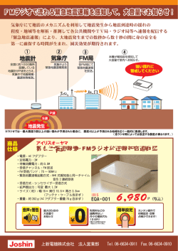
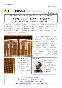
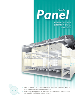
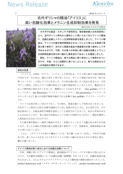
* 3 REMOTE CONTROL PANEL RCP-700/701 電気製品は、安全のための注意事項を守らないと、火災 や人身事故になることがあります。 このオペレーションマニュアルには、 事故を防ぐための重要な注意事項と製 品の取り扱いかたを示してあります。 このオペレーションマニュアルと別冊 の「安全のために」をよくお読みのうえ、製品を安全にお使いください。お 読みになったあとは、いつでも見られるところに必ず保管してください。 OPERATION MANUAL 1st Edition (Revised 4) Japanese/English - 8 0 0 - 0 5 0 - 0 5 * For the customers in the USA This equipment has been tested and found to comply with the limits for a Class A digital device, pursuant to Part 15 of the FCC Rules. These limits are designed to provide reasonable protection against harmful interference when the equipment is operated in a commercial environment. This equipment generates, uses, and can radiate radio frequency energy and, if not installed and used in accordance with the instruction manual, may cause harmful interference to radio communications. Operation of this equipment in a residential area is likely to cause harmful interference in which case the user will be required to correct the interference at his own expense. You are cautioned that any changes or modifications not expressly approved in this manual could void your authority to operate this equipment. The shielded interface cable recommended in this manual must be used with this equipment in order to comply with the limits for a digital device pursuant to Subpart B of Part 15 of FCC Rules. For customers in Canada This Class A digital apparatus complies with Canadian ICES-003. Pour les utilisateurs au Canada Cet appareil numérique de la classe A est conforme à la norme NMB-003 du Canada. For the customers in Europe This product with the CE marking complies with the EMC Directive (89/336/EEC) issued by the Commission of the European Community. Compliance with this directive implies conformity to the following European standards: • EN55103-1: Electromagnetic Interference (Emission) • EN55103-2: Electromagnetic Susceptibility (Immunity) This product is intended for use in the following Electromagnetic Environment(s): E1 (residential), E2 (commercial and light industrial), E3 (urban outdoors) and E4 (controlled EMC environment, ex. TV studio). Pour les clients européens Ce produit portant la marque CE est conforme à la Directive sur la compatibilité électromagnétique (EMC) (89/336/CEE) émise par la Commission de la Communauté européenne. La conformité à cette directive implique la conformité aux normes européennes suivantes: • EN55103-1: Interférences électromagnétiques (émission) • EN55103-2: Sensibilité électromagnétique (immunité) Ce produit est prévu pour être utilisé dans les environnements électromagnétiques suivants: E1 (résidentiel), E2 (commercial et industrie légère), E3 (urbain extérieur) et E4 (environnement EMC contrôlé, ex. studio de télévision). Für Kunden in Europa Dieses Produkt besitzt die CE-Kennzeichnung Und erfüllt die EMV-Richtlinie (89/336/EWG) der EGKommission. Angewandte Normen: • EN55103-1: Elektromagnetische Verträglichkeit (Störaussendung) • EN55103-2: Elektromagnetische Verträglichkeit (Störfestigkeit), für die folgenden elektromagnetischen Umgebungen: E1 (Wohnbereich), E2 (kommerzieller und in beschränktem Maße industrieller Bereich), E3 (Stadtbereich im Freien) und E4 (kontrollierter EMVBereich, z.B. Fernsehstudio). 目次 概要 .................................................................................................................. 2(J) 各部の名称と働き ............................................................................................ 3(J) 操作パネル ......................................................................................................... 3(J) コネクターパネル ............................................................................................. 6(J) 仕様 .................................................................................................................. 7(J) BVP-700シリーズカメラシステムのマニュアル構成 BVP-700シリーズのカメラシステムでは、オペレーショ ステムの構築のしかた、設置、接続、システムとして使 ンマニュアルの他に、メンテナンスマニュアルとシステ 用するために必要な準備、システムとしての操作など、 ムマニュアルが用意されています。 システム全体に関する説明が記載されています。 オペレーションマニュアルでは、機器の概要、各部の名 オペレーションマニュアルとメンテナンスマニュアル 称と働き、および仕様など、その機器固有の機能や特性 は、システムを構築する各機器に付属し、システムマ について説明します。 ニュアルは別売りになっています。 メンテナンスマニュアルとシステムマニュアルには、シ 1(J) 概要 リモートコントロールパネルRCP-700/701は、ソニーのス RCP-700/701の主な特長は次のとおりです。 タジオ/中継用CCDカラービデオカメラBVP-700シリーズの 基本機能をリモートコントロールするためのコントロール 操作性を重視したレイアウト パネルです。 カメラの基本機能のコントロールに必要なボタンやつまみ 本機は、専用のケーブルで他のRCPシリーズのコントロー 類が、操作性を最優先に配置され、限定された面積なが ルパネル (RCP-740/741など) に接続して使用します。 ら、スムーズな操作が可能です。 カメラコントロールユニットCCU-700、カメラコマンド ネットワークユニットCNU-700に直接接続して使用するこ 他のコントロールパネルとの併用により柔軟な対応が可能 ともできます。 基本機能のコントロールを本機で行い、よりきめ細かな調 整が必要な場合、他のRCPシリーズのコントロールパネル RCP-700とRCP-701では、アイリス/マスターブラック調整 やマスターセットアップユニットMSU-700などを使用する 部の構成・形状が異なるだけで、他の機能は共通です。 など、他のコントロールパネルとの組み合わせにより、撮 アイリス/マスターブラック調整部は、RCP-700ではジョイ 影条件に応じた柔軟な対応が可能になります。 スティック (レバー) タイプ、RCP-701ではつまみになって います。 デジタル回線による接続 RCP-700/701でのアイリスおよびマスターブラックの調整 他のユニットと本機との間は、デジタル回線により信号の は、常に絶対値モードで行われます。 受け渡しを行います。1本の接続ケーブル(CCA-5) ですべて の信号の授受を確実に行うことができます。本機には接続 ケーブルを介して電源が供給されます。 19インチのラックに6台取り付け可能 本機は、19インチのEIA標準ラックに6台並べて取り付ける ことができます。高さは4ユニットです。 2(J) 各部の名称と働き 操作パネル 1 PANEL ACTIVEボタン 2 WHITEボタン 3 BLACKボタン RCP-700 S PANEL ACTIVE CALL 4 CALLボタン WHITE BLACK 5 WHITE調整つまみ WHITE 6 BLACK調整つまみ BLACK MASTER SLAVE !™ AUTOボタン 8 IRIS/MB ACTIVEボタン EXT AUTO 7 EXTインジケーター IRIS/MB ACTIVE 9 SENSつまみ !£ カメラナンバー/タリー表示部 SENS !º COARSEつまみ CLOSE OPEN COARSE !¢ マスターブラック調整リング ALARM !¡ ALARMインジケーター !∞ IRISレバー兼プレビュースイッチ IRIS REMOTE CONTROL PANEL 1 PANEL ACTIVEボタン 2 WHITEボタン 3 BLACKボタン RCP-701 S PANEL ACTIVE CALL 4 CALLボタン WHITE BLACK WHITE 5 WHITE調整つまみ BLACK 6 BLACK調整つまみ MASTER SLAVE !™ AUTOボタン AUTO 7 EXTインジケーター 8 IRIS/MB ACTIVEボタン EXT IRIS/MB ACTIVE !£ カメラナンバー/タリー表示部 9 SENSつまみ !¢ MASTER BLACKつまみ SENS !º COARSEつまみ MASTER BLACK CLOSE OPEN COARSE ALARM !¡ ALARMインジケーター !∞ IRISつまみ !§ アイリスゲージ IRIS PREVIEW REMOTE CONTROL PANEL !¶ PREVIEWボタン 3(J) 各部の名称と働き RCP-700/701共通 5 WHITE (ホワイトバランス手動調整) つまみ ホワイトバランス手動調整用のつまみです。R信号、B信号 1∼!£は、RCP-700/701に共通です。 1 PANEL ACTIVE (パネルアクティブ) ボタン 押して点灯させると、本機に接続したカメラシステムをコ ントロールできる状態 (パネルアクティブ状態) になりま をそれぞれに調整します。 6 BLACK (ブラックバランス手動調整) つまみ ブラックバランス手動調整用のつまみです。R信号、B信号 をそれぞれに調整します。 す。このときIRIS/MB ACTIVEボタンも同時に点灯しま す。 7 EXT (レンズエクステンダー) インジケーター レンズエクステンダーを使用しているとき点灯します。 2 WHITE (ホワイトバランス自動調整) ボタン 押すと、ホワイトバランスが自動調整されます。 調整中はボタンが点灯し、調整が完了すると消灯します。 自動調整実行中にもう1度このボタンを押すと、自動調整が 中止され、ボタンが点滅します。もう1度ボタンを押すと点 滅が止まります。 8 IRIS/MB ACTIVE (アイリス/マスターブラックアク ティブ) ボタン 押して点灯させると、本機で絞りとマスターブラックの調 整が行えます。 PANEL ACTIVEボタンを押すと、このボタンも同時に点灯 します。 ご注意 自動調整中にエラーが発生した場合は、点灯させたボタン 9 SENS (アイリス調整範囲) つまみ が点滅します。 絞りの手動調整を行うとき、絞りの可変範囲の調整に使用 します。 3 BLACK (ブラックバランス自動調整) ボタン ◆「アイリス調整機能」表 (次ページ) をご覧ください。 押すと、ブラックバランス、ブラックセットが自動調整さ れます。 !º COARSE (アイリス粗調整) つまみ 調整中はボタンが点灯し、調整が完了すると消灯します。 絞りの手動調整を行うとき使用します。 自動調整実行中にもう1度このボタンを押すと、自動調整が 中止され、ボタンが点滅します。もう1度ボタンを押すと点 滅が止まります。 ご注意 ◆「アイリス調整機能」表 (次ページ) をご覧ください。 !¡ ALARM (アラーム) インジケーター システムに異常が発生し、カメラヘッドやCCU-700で自己 診断機能が動作すると、赤く点灯します。 自動調整中にエラーが発生した場合は、点灯させたボタン が点滅します。 !™ AUTO (自動絞り) ボタン 押して点灯させると、レンズの絞りが入力光に応じて自動 4 CALL (コール) ボタン 的に調整されます。 押すとビデオカメラにコール信号が送出され、カメラ側の ボタン点灯時は、絞りの自動調整の基準値を±1Fの範囲で CALLボタンが点灯します。また、カメラのタリーランプと 微調整することができます。 CCU-700のレッドタリーランプは、それぞれ点灯していた もう1度押すと消灯し、絞りの手動調整が可能になります。 場合は消灯し、消灯していた場合は点灯します。 カメラ側でCALLボタンが押されると、本機のCALLボタン が点灯し、ブザーが鳴ります。 4(J) !£ カメラナンバー/タリー表示部 (マスター/スレーブ表 RCP-701 示付き) 本機でコントロールしているカメラのナンバーが、オレン !¢ MASTER BLACK (マスターブラック調整) つまみ ジ色で表示されます。 マスターブラックを手動調整します。 カメラにレッドタリー信号が入力されると、背景が赤く点 灯し、ナンバーは黒で表示されます。グリーンタリー信号 !∞ IRIS (アイリス調整) つまみ が入力されると背景が緑に点灯し、ナンバーは黒で表示さ AUTOボタン消灯時は、レンズの絞りを手動調整します。 れます。 AUTO IRISボタン点灯時は、絞りの自動調整の基準値を微 レッドタリー信号とグリーンタリー信号が同時に入力され 調整(±1F) できます。 た場合は、背景の左半分が赤、右半分が緑に点灯します。 ◆「アイリス調整機能」表 (左下) をご覧ください。 複数のカメラのホワイトバランスを同時に調整するマス ター/スレーブモードで、本機でコントロールしているカメ !§ アイリスゲージ ラがマスターに設定されている場合は、表示部左上隅 白いマーカーラインが、アイリス調整つまみのクリック位 (MASTER側) のLEDがオレンジ色に点灯します。スレーブ 置になります。ゲージを回して使用頻度の高い位置にマー に設定されている場合は、表示部右上隅 (SLAVE側) のLED カーラインを合わせておくと、アイリス調整つまみの設定 がオレンジ色に点灯します。 基準として使用できます。 ゲージは360 °回転しますので、クリック位置が不要の場 合は、マーカーラインがつまみの回転範囲の外になるよう RCP-700 に設定してください。 !¢ マスターブラック調整リング !¶ PREVIEW (プレビュー) ボタン マスターブラックの手動調整を行います。 押すとPREVIEW端子のプレビュー用キー信号が接続され ます。 !∞ IRIS (アイリス調整) レバー兼プレビュースイッチ AUTOボタン消灯時に、スロット方向に動かすと、レンズ の絞りを手動で調整できます。 AUTOボタン点灯時は、絞りの自動調整の基準値を微調整 (±1F) します。 軸方向に押すと、PREVIEW端子のプレビュー用キー信号 が接続されます。 ◆「アイリス調整機能」表 (下記) をご覧ください。 アイリス調整機能 IRISレバー (RCP-700) IRISつまみ (RCP-701) SENSつまみとCOARSEつまみ で設定した可変範囲内で絞りを 調整します。 COARSEつまみ CLOSE側の下限を設定します。 SENSつまみ COARSEつまみで設定した CLOSE側を基準にして、OPEN 側の上限を設定します。 5(J) 各部の名称と働き コネクターパネル PREVIEW REMOTE 2 REMOTE端子 1 PREVIEW端子 1 PREVIEW (プレビュー) 端子 (6ピン) プレビュー信号を出力します。 RCP-701では、PREVIEWボタン点灯用電源をビデオスイッ チャーなどから受けることもできます。 2 REMOTE (リモート) 端子 (8ピン) カメラコントロールユニットのRCP/CNU端子、カメラコ マンドネットワークユニットのRCP端子、または他のRCP シリーズのリモートコントロールパネルのAUX端子に接続 します。 6(J) 仕様 一般 電源 DC 10∼30 V 消費電力 最大2 W 最大ケーブル長 200 m 動作温度 0℃∼45℃ 最大外形寸法 68 × 177 × 67 mm (幅/高さ/奥行き) 質量 0.9 kg 入出力 REMOTE 8ピンマルチコネクター (1) PREVIEW 6ピン (1) 付属品 PREVIEW端子接続用6ピンプラグ (1) オペレーションマニュアル (1) 本機の仕様および外観は、改良のため予告なく変更するこ とがありますが、ご了承ください。 7(J) Table of Contents Overview ....................................................................................... 2(E) Location and Function of Parts and Controls ........................... 3(E) Operation Panel ........................................................................ 3(E) Connector Panel ........................................................................ 6(E) Specifications ................................................................................ 7(E) Manuals for the BVP-700-series video camera system Three types of manuals are provided for the BVP-700-series video camera system: an Operation Manual, a Maintenance Manual, and a System Manual. The Operation and Maintenance Manuals are provided for each device used in the system, and the System Manual is provided as an option. In the Operation Manual, specific functions and characteristics of the device, such as features, functions of each part and specifications, are described. In the Maintenance and System Manuals, you will find general information on the system, such as possible system configurations, the setup method, connections, and system preparations and operations. 1(E) Overview The RCP-700/701 Remote Control Panel is designed for remote control of elementary functions of the BVP-700-series Color Video Camera. The panel is used in connection with another RCP-series Remote Control Panel (such as RCP-740/741) via a special cable. It can also be directly connected to the CCU-700/700P Camera Control Unit or the CNU-700 Camera Command Network Unit. The RCP-700 and RCP-701 are completely identical in their functions except with respect to the iris and master black adjustments. For the iris and master black adjustments, the RCP-700 uses a joystick-type control, while the RCP-701 uses rotary knobs. The iris and master black adjustments on the RCP700/701 are always made in Absolute mode. The principal features of the RCP-700/701 are as follows. Control parts arrangement for high operability The parts required to control the elementary functions of the BVP-700-series cameras are arranged for highest possible operability. This enables smooth operations even in limited panel space. Flexible camera control through use in combination with another control panel You can use this panel to quickly control elementary functions and, when more detailed adjustments are required, other RCP-series panels or the MSU-700 Master Setup Unit. Thus, through combined use with other controllers, the most desirable operating emvironment can be flexibly selected according to conditions. Signal transmission via a digital line Between this remote control panel and another unit, signals are digitally transmitted via a single connection cable (CCA-5), ensuring a reliable signal. Six units mountable on a 19-inch rack Up to six units of this control panel can be mounted in a line on a 19-inch EIA standard rack. The height is four rack units. 2(E) Location and Function of Parts and Controls Operation Panel 1 PANEL ACTIVE button 2 WHITE button 3 BLACK button RCP-700 S PANEL ACTIVE CALL 4 CALL button WHITE BLACK 5 WHITE knobs WHITE BLACK MASTER SLAVE !™ AUTO button EXT AUTO 6 BLACK knobs 7 EXT indicator 8 IRIS/MB ACTIVE button IRIS/MB ACTIVE !£ Camera number/ 9 SENS control knob tally indication window SENS !º COARSE control knob CLOSE OPEN COARSE !¢ Master black control ring ALARM !¡ ALARM indicator !∞ IRIS control lever/preview switch IRIS REMOTE CONTROL PANEL 1 PANEL ACTIVE button 2 WHITE button 3 BLACK button RCP-701 S PANEL ACTIVE CALL 4 CALL button WHITE BLACK 5 WHITE knobs WHITE BLACK MASTER !™ AUTO button !£ Camera number/ SLAVE EXT AUTO 6 BLACK knobs 7 EXT indicator 8 IRIS/MB ACTIVE button IRIS/MB ACTIVE tally indication window 9 SENS control knob !¢ MASTER BLACK control SENS !º COARSE control knob MASTER BLACK CLOSE OPEN COARSE ALARM !¡ ALARM indicator !∞ IRIS control !§ Iris gauge IRIS PREVIEW REMOTE CONTROL PANEL !¶ PREVIEW button 3(E) Location and Function of Parts and Controls Parts common to the RCP-700/701 Items 1 through !£ are common to the RCP-700 and RCP-701. 1 PANEL ACTIVE button Press and light up the button to permit this panel to control the camera system (Panel active status). The IRIS/MB ACTIVE button also lights. 2 WHITE (white balance) button Press to automatically adjust the white balance. The button lights during adjustment and goes dark when adjustment is completed. If you press this button when lit, the automatic adjustment is canceled and the button flashes. To stop the flashing, press the button again. Note If an error occurs during adjustment, the pressed button flashes. 3 BLACK (black balance) button Press to automatically adjust the black balance and black set. The button lights during adjustment and goes dark when adjustment is completed. If you press this button when lit, the automatic adjustment is canceled and the button flashes. To stop the flashing, press the button again. Note If an error occurs during adjustment, the pressed button flashes. 4 CALL button Press to send a call signal to the video camera, on which the CALL button lights. The tally lamps on the camera and the red tally lamp on the CCU-700/ 700P light when not lit, or go dark when lit. When the CALL button on the video camera is pressed, the CALL button on this panel lights and a buzzer sounds. 5 WHITE (white balance manual adjustment) knobs Used to manually adjust the white balance. Adjust the R and B signals, respectively. 4(E) 6 BLACK (black balance manual adjustment) knobs Used to manually adjust the black balance. Adjust the R and B signals, respectively. 7 EXT (lens extender) indicator Lights when the lens extender is used. 8 IRIS/MB ACTIVE (iris/master black active) button Press and light up this button to enable the iris/ master black control block of the panel. When the PANEL ACTIVE button is pressed, this button also lights. 9 SENS (sensitivity) control knob Used for manual iris adjustment. See the table “Iris adjustment functions” on the next page. !º COARSE control knob Used for manual iris adjustment. See the table “Iris adjustment functions” on the next page. !¡ ALARM indicator Lights when trouble occurs in the camera system and the self-diagnostic function activates at the video camera or the CCU-700/700P. !™ AUTO button Press and light the button to automatically adjust the iris according to the amount of input light. If you press the button when lit, it goes dark and manual iris adjustment is enabled. !£Camera number/tally indication window (incorporated with MASTER/SLAVE indications) The number of the camera being controlled from this panel is displayed in orange. When a red tally signal is sent to the camera, the number is displayed in black and the background of the number lights in red. When a green tally signal is sent to the camera, the number is displayed in black and the background of the number lights in green. When both red and green tally signals are simultaneously sent, the left half of the background lights in red and the right half lights in green. In Master/Slave mode to adjust the white balance of multiple cameras, the upper-left (MASTER) corner lights in orange when the camera being controlled from this panel is designated as the master unit, and the upper-right (SLAVE) corner lights in orange when designated as a slave unit. RCP-700-exclusive parts !¢Master black control ring Turn to manually adjust the master black. RCP-701-exclusive parts !¢MASTER BLACK control Manually adjust the master black. !∞IRIS control When the AUTO button is not lit, you can adjust the iris manually by turning the control. When the AUTO button is lit, the reference value for automatic iris adjustment can be set in a range of ±1f with this control. See the table “Iris adjustment functions” shown left below. !§Iris gauge The white line on the gauge provides a click position for the IRIS control. Turn the gauge to set the line to the most frequently used iris position, and it can be used as the reference for manual iris adjustment. The gauge rotates infinitely in either direction. When no click position is required, set the line outside the rotation range of the IRIS control. !¶PREVIEW button Connects the key signal for preview at the PREVIEW connector. !∞IRIS control lever/preview switch When the AUTO button is not lit, you can adjust the iris manually by moving this lever. When the AUTO button is lit, the reference value for automatic iris adjustment can be set in a range of ±1f with this lever. Push it axially to connect the key signal for preview at the PREVIEW connector. See the table “Iris adjustment functions” below. Iris adjustment functions Adjusts the iris within the IRIS lever (RCP-700) variable range set by the IRIS control (RCP-701) SENS and COARSE controls. COARSE control SENS control Sets the lower limit for CLOSED. Sets the upper limit for OPEN according to CLOSED value set by the COARSE control. 5(E) Location and Function of Parts and Controls Connector Panel PREVIEW REMOTE 2 REMOTE connector 1 PREVIEW connector 1 PREVIEW connector (6-pin) Supplies preview signals. The RCP-701 receives the power from an external device, such as a video switcher, to light the PREVIEW button through this connector. 2 REMOTE connector (8-pin) Connect to the RCP/CNU connector of the CCU700/700P, the RCP connector of the CNU-700 or the AUX connector of another RCP-series Remote Control Panel. 6(E) Specifications General Power requirements 10 to 30 V DC Power consumption 2 W max. Maximum cable length 200 m (656 feet) Operating temperature 0°C to 45°C (32°F to 113°F) Dimensions 68 × 177 × 67 mm (w/h/d) (23/4 × 7 × 23/4 inches) including projecting parts and controls Mass 0.9 kg (2 lb) Inputs/outputs REMOTE PREVIEW 8-pin multiconnector (1) 6-pin (1) Supplied accessories 6-pin plug for preview (1) Operation Manual (1) Design and specifications are subject to change without notice. 7(E) The material contained in this manual consists of information that is the property of Sony Corporation and is intended solely for use by the purchasers of the equipment described in this manual. Sony Corporation expressly prohibits the duplication of any portion of this manual or the use thereof for any purpose other than the operation or maintenance of the equipment described in this manual without the express written permission of Sony Corporation. * 3 Sony Corporation RCP-700/701 (SY) - 8 0 0 - 0 5 0 - 0 5 * Printed in Belgium 2008. 02. 08 1995
© Copyright 2026 Paperzz