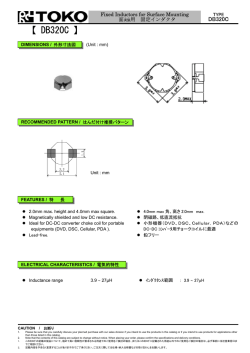
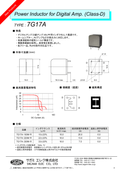
Fixed Inductors for Cellular Phone
携帯電話用面実装 固定インダクタ
づ
け
TYPE
D412F
【 D412F 】
DIMENSIONS / 外形寸法図
(Unit : mm)
RECOMMENDED PATTERN / はんだ付け推奨パターン
Resist Zone
FEATURES / 特
!
!
!
!
!
長
Low profile (1.2.mm max height) and 4.8mm max
!
小形薄形 (4.8mm max 角、高さ 1.2mm max)
square.
Suitable as Inductors for Cellular phone
Rigid outer frame structure ensures anti-shock
proof
Large current handling capability.
Lead-free.
!
!
!
!
携帯電話用インダクタに最適
外枠強化構造により日米欧の耐落下衝撃性に対応
大電流対応
鉛フリー
ELECTRICAL CHARACTERISTICS / 電気的特性
! Inductance range
CAUTION
1.
2.
1.
2.
: 2.2 ∼ 47µH
! インダクタンス範囲
: 2.2 ∼ 47µH
/ お断り
Please be sure that you carefully discuss your planned purchase with our sales division if you intend to use the products in this catalog for applications where extremely high reliability is
required or if you intend to use products for applications other than those listed in this catalog.
Note that the contents of this catalog are subject to change without notice. When placing your order, please confirm the specifications and delivery conditions.
このカタログの記載の製品について、極めて高い信頼性が要求される用途でのご使用をご検討の場合、またはこのカタログに記載された用途以外でのご使用をご検討の場合は、必ず事前に当社営業窓口ま
でご相談ください。
記載内容を予告なく変更することがありますのでご了承ください。ご注文に際しては仕様・納入仕様書などの取り交わしをお願いします。
Fixed Inductors for Cellular Phone
携帯電話用面実装 固定インダクタ
づ
TYPE
け
D412F
SELECTION GUIDE FOR STANDARD COILS / 標準品一覧表
東光品番
TOKO
Part
インダクタンス
許容差
直流抵抗
直流重畳許容電流
温度上昇許容電流
DC
Inductance
Temperature
Resistance
Decrease Current
Rise current
Inductance Tolerance
Number
-10%
-30%
(Ω)Typ (Ω)Max (A)Typ (A) Max (A) Typ (A) Max (A)Typ
1.55
0.12
0.14
1.52
1.14
1.78
1.33
(A)Max
(μH)
(%)
972AS-2R2M
2.2
±20
972AS-3R3M
3.3
±20
0.17
0.20
1.19
0.90
1.36
1.02
1.29
1.09
972AS-4R7M
4.7
±20
0.19
0.22
1.08
0.80
1.28
0.96
1.18
1.00
972AS-6R8M
6.8
±20
0.29
0.35
0.88
0.66
1.03
0.77
0.90
0.76
972AS-8R2M
972AS-100M
8.2
10
±20
±20
0.32
0.40
0.38
0.48
0.82
0.71
0.61
0.53
0.98
0.87
0.73
0.65
0.89
0.84
0.75
0.71
972AS-120M
12
±20
0.52
0.62
0.70
0.52
0.82
0.61
0.74
0.62
972AS-150M
15
±20
0.60
0.70
0.59
0.44
0.72
0.54
0.68
0.58
972AS-180M
972AS-220M
972AS-270M
18
22
27
±20
±20
±20
0.71
0.79
1.05
0.85
0.96
1.26
0.52
0.48
0.43
0.39
0.36
0.32
0.66
0.60
0.54
0.50
0.45
0.40
0.66
0.60
0.50
0.56
0.51
0.42
972AS-330M
33
±20
1.25
1.50
0.39
0.29
0.48
0.36
0.47
0.40
972AS-390M
39
±20
1.39
1.68
0.35
0.26
0.46
0.35
0.46
0.39
972AS-470M
47
±20
1.57
1.88
0.32
0.24
0.42
0.31
0.43
0.36
(1)Inductance is measured with a LCR meter
4284A* or equivalent.
(2) DC resistance is measured with a Digital
Multimeter TR6871 (Advantest) or equivalent.
(3) Maximum allowable DC current is that which
causes a 30% inductance reduction from the
initial value, or coil temperature to rise by
40℃ whichever is smaller.
(Reference ambient temperature 20℃)
Agilent Technologies
1.31
(1) インダクタンスは LCR メータ 4284A*または同等品により
測定する
(2) 直流抵抗はデジタルマルチメータ TR6871(Advantest)ま
たは同等品により測定する
(3) 最大許容電流は、直流重畳電流を流した時インダクタ
ンスの値が初期値より 30%減少する直流電流値、ま
たは直流電流により、コイルの温度が 40℃上昇の何
れか小さい値です。
(周囲温度 20℃を基準とする。)
株式会社
© Copyright 2026 Paperzz