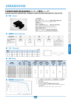
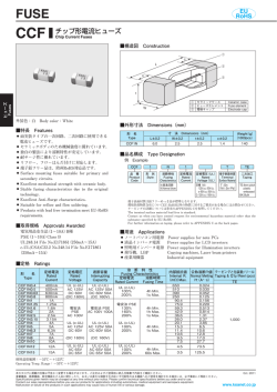
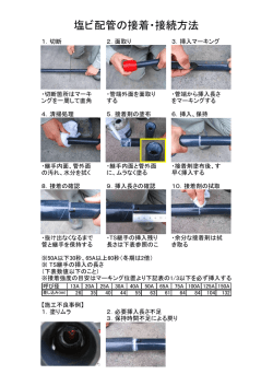
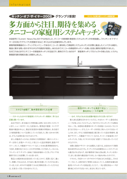
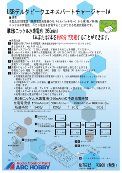
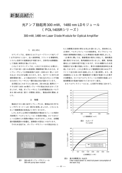
MICRO FUSE
CCP
EU
RoHS
回路保護用素子
Chip Circuit Protectors
■構造図 Construction
L
①
W
h
t
e
Fuses
ヒューズ
外装色:黒 Body color:Black
●
●
●
●
●
●
●
●
●
① ヒューズエレメント Fuse element
② 電極 Electrode ③ バッファー Buffer
④ モールド樹脂 Molded resin
②
■外形寸法 Dimensions
■特長 Features
●
d
③
④
寸 法 Dimensions(mm)
W±0.2
t±0.2
h±0.1
e±0.1
1.6
1.2
0.8
1.2
2.5
2.2
1.9
1.7
形名 Type
(Inch Size Code) L±0.2
2B
(1206)
3.2
2E
(1210)
3.2
電流に対してすみやかに発熱、発煙することな
過
く回路を遮断します。
金 属電極であり、端子強度、はんだ付け性に優れ
ています。
外装はモールド成型品であり、寸法精度が良く、
搭載性に優れています。
端子鉛フリー品は、欧州RoHS対応品です。
リフロー、フローはんだ付けに対応します。
Immediate cutting off against excessive current of
circuit without generating heat and fuming.
Excellent terminal strength and solderability due to
metal electrode.
Excellent dimension accuracy, mountability and
shock-resistance due to plastic molding.
Applicable to both reflow and flow solderings.
Products with lead free termination meet EU-RoHS
requirements.
Weight(g)
d±0.1 (1000pcs)
0.6
13.0
0.5
38.5
■品名構成 Type Designation
例 Example
CCP
2E
20
品 種
Product
Code
サイズ
Size
定 格
Rating
2B:3.2×1.6mm
2E:3.2×2.5mm
溶断倍率
Fusing
Magnification
T
TE
端子表面材質
Terminal
Surface Material
二次加工
Taping
TE:4mm pitch
空欄 Nil:200%(2B), 250%(2E) T:Sn
(Nil:Sn/Pb) plastic
H : 200%(2E)
embossed
BK:Bulk
端子表面材質は鉛フリーめっき品が標準となります。
環境負荷物質含有についてEU-RoHS以外の物質に対するご要求がある場合にはお問合せください。
テーピングの詳細については巻末のAPPENDIX Cを参照してください。
The terminal surface material lead free is standard.
Contact us when you have control request for environmental hazardous material other than the
substance specified by EU-RoHS.
For further information on taping, please refer to APPENDIX C on the back pages.
■取得規格 Approvals Awarded
UL 248.14 File No. E131375
c-UL (CSA) C22.2 No. 248.14 File No. E131375
■定格 Ratings
形 名
Type
CCP2B15
CCP2B20
CCP2B25
CCP2B30
CCP2B35
CCP2B40
CCP2B50
CCP2B63
CCP2B80
CCP2B100
CCP2E10
CCP2E13
CCP2E15
CCP2E20
CCP2E25
CCP2E30
CCP2E35
CCP2E38
CCP2E40
CCP2E45
CCP2E50
CCP2E63
CCP2E100
CCP2E10H
CCP2E13H
CCP2E15H
CCP2E20H
CCP2E25H
CCP2E30H
CCP2E35H
CCP2E38H
CCP2E40H
CCP2E45H
CCP2E50H
CCP2E63H
定格電流
Rated
Current
0.75A
1.00A
1.25A
1.50A
1.75A
2.00A
2.50A
3.15A
4.00A
5.00A
0.4A
0.52A
0.6A
0.8A
1.0A
1.2A
1.4A
1.5A
1.6A
1.8A
2.0A
2.5A
4.00A
0.50A
0.65A
0.75A
1.00A
1.25A
1.50A
1.75A
1.90A
2.00A
2.25A
2.50A
3.15A
溶断電流
Fusing
Current
1.5A
2.0A
2.5A
3.0A
3.5A
4.0A
5.0A
6.3A
8.0A
10.0A
1.0A
1.3A
1.5A
2.0A
2.5A
3.0A
3.5A
3.8A
4.0A
4.5A
5.0A
6.25A
10.0A
1.0A
1.3A
1.5A
2.0A
2.5A
3.0A
3.5A
3.8A
4.0A
4.5A
5.0A
6.3A
溶断時間
Fusing
Time
溶断電流
印加時に
1秒以内
Fusing
current
Max. 1s
溶断電流
印加時に
1秒以内
Fusing
current
Max. 1s
溶断電流
印加時に
1秒以内
Fusing
current
Max. 1s
内部抵抗値
Internal R.
Max.(mΩ)
150
100
75
60
50
45
35
23
19
15
200
170
150
100
75
60
50
48
45
40
35
23
15
200
170
150
100
75
60
50
48
45
40
35
23
テーピングと包装数/リール
使用温度範囲
Operating Temp. Taping & Q'ty/Reel (pcs)
Range
TE
定格電圧
Rated
Voltage
定格周囲温度
Rated
Ambient Temp.
24V
※
(40V/76V)
+70℃
−40℃〜
+125℃
3,000
72V
+70℃
−40℃〜
+125℃
2,000
72V
+70℃
−40℃〜
+125℃
2,000
※高定格電圧品(76V:0.75A〜3.15A、40V:4A〜5A)もございます。お問い合わせください。※High rated voltage (76V : 0.75A〜3.15A, 40V : 4A〜5A) is also available. Please consult with us.
本カタログに掲載の仕様は予告なく変更する場合があります。ご注文およびご使用前に納入仕様書で内容をご確認ください。
Oct. 2016
車載機器、医療機器、航空機器など人命に関わったり、あるいは甚大な損害を引き起こす可能性のある機器へのご使用を検討される場合には、必ず事前にご相談ください。
Specifications given herein may be changed at any time without prior notice. Please confirm technical specifications before you order and/or use.
Contact our sales representatives before you use our products for applications including automotives, medical equipment and aerospace equipment.
www.koaglobal.com
Malfunction or failure of the products in such applications may cause loss of human life or serious damage.
■ディレーティング Derating
■周囲温度による定格電流の軽減率
Rated Current Derating Rate
常電流
定
定常電流が繰り返しパルスの場合には、定常電流波形のピーク値
を定常電流値とします。
● 温度ディレーティング
70℃以上の周囲温度で使用する場合には、温度補正が必要となり
ますので、右図のディレーティング係数を考慮ください。
● Stationary current
Regard the peak of stationary current waveform as stationary
current value when the stationary current is repeated pulse.
● Temperature Derating
Rated current needs to be derated if used at an ambient temperature of 70℃ or more. Refer to the derating coefficient on the
right figure.
●
100
80
80
60
60
40
40
20
定格電流比(%)
Percent rated current
定格電流比(%)
Percent rated current
100
20
0
-40 -20
20
40
60 80 100 120 140 160 180
70
125
175
周囲温度 Ambient temperature(℃)
40 60 80 100 120 140 160 180
70
125
175
Fuses
0
20
ヒューズ
0
-40 -20
0
■溶断特性 Fusing Characteristics
(標準溶断特性 Average
Fusing Characteristics)
周囲温度 Ambient
temperature(℃)
10 131520 2530 35 38 40 45 50
63
100
15 20 25303540 50
63
80
100
10
0.1
0.1
0.01
0.01
0.001
溶断時間(s)
Fusing time
1
80
100
0
1
2
3
4
5
6
7
8
9
10
11
12
CCP2E・CCP2E□H
10 131520 2530 35 38 40 45 50
10
溶断時間(s)
Fusing time
溶断時間(s)
Fusing time
1
63
1
0.1
0.1
0.01
0.01
0.001
0
1
2
0
1
2
3
4
5
6
7
8
9
10
11
3
4
100
5
6
7
8
9
10
11
12
溶断電流値 Fusing current(A)
溶断電流値 Fusing current(A)
0.001
63
1
溶断時間(s)
Fusing time
15 20 25303540 50
10
10
CCP2B
12
0.001
0
1
2
3
4
5
6
7
8
9
10
11
12
溶断電流値 Fusing current(A)
溶断電流値 Fusing current(A)
■性能 Performance
試験項目
Test Items
規格値 Performance Requirements
ΔR±%
保証値 Limit
代表値 Typical
試験方法
Test Methods
溶断特性
Fusing characteristics
1秒以内
Within 1s
—
CCP2B:200% of rated current shall be carried.
CCP2E:250% of rated current shall be carried.
CCP2E□H:200% of rated current shall be carried.
開回路電圧
Open circuit voltage
発煙、発火、破裂等の
異常がないこと。
No fusing, flaming, explosion.
—
溶断後、両電極間に直流電圧を印加する。
Apply DC voltage between the termination after fusing.
CCP2B:24V CCP2E, CCP2E□H:72V
残留抵抗値
Residual resistance
10kΩ以上
10kΩ or more
—
溶断後の直流抵抗値
Measure DC resistance after fusing
電極強度
Bending test
電極剥離、導通断線等の異常がないこと。
—
No mechanical damages.
支持点間隔90mm、曲げ幅10mm、1回
Distance between holding points 90mm, bending width 10mm, 1time.
はんだ耐熱性
Resistance to soldering heat
10
260℃±5℃, 10s±0.5s, 2 cycles.
はんだ付け性
Solderability
95%以上が新しいはんだで覆われること。
—
95% coverage min.
230℃±5℃, 3s±0.5s
通電寿命
Load life
10
3
70℃±3℃, 1000h, 定格電流, 1.5時間ON / 0.5時間OFFの周期
Rated current, 1.5h ON / 0.5h OFF cycle
耐湿通電寿命
Load life moisture
10
1.5
40℃±2℃, 90%〜95%RH, 1000h, 定格電流, 1.5時間ON/0.5時間OFFの周期
Rated current, 1.5h ON / 0.5h OFF cycle
温度急変
Rapid change of temperature
10
4
−40℃(30min)/+125℃(30min)10 cycles
耐溶剤性
Resistance to solvent
表示消え等、外観に異常がないこと。
No evidence of damages to
protective coating and marking.
—
MIL-STD-202F準拠
Conforming to MIL-STD-202F
2.5
■使用上の注意 Precautions for Use
●
●
●
●
●
●
定格電流品(4A、5A)に関しましては製品自体の発熱が大きくなります。実装条件を十分に考慮いただき、製品表面の温度上昇を
高
70℃以下にて使用頂けますようお願い致します。
イオン性不純物が付着していると部品の耐湿性、耐腐食性等を劣化させる場合があります。イオン性物質が付着する場合は、十分な
洗浄を行ってください。
ヒューズの選定に際しては、必ず本カタログ内の「ヒューズの使用上の注意事項」を合わせてご確認の上、お問い合わせください。
For type 4A and 5A, heating value from the products is high. Please consider the mouting condition and keep the surface temperature
under 70℃ when you use the products.
Ionic impurities may deteriorate resistances to humidity and corrosion of the product. Please wash the product thoroughly when ionic
substances are to be attached.
When you select fuse product, please make sure to confirm "Precautions for Use of Fusing Components" in this catalogue and ask
KOA sales.
本カタログに掲載の仕様は予告なく変更する場合があります。ご注文およびご使用前に納入仕様書で内容をご確認ください。
Oct. 2016
車載機器、医療機器、航空機器など人命に関わったり、あるいは甚大な損害を引き起こす可能性のある機器へのご使用を検討される場合には、必ず事前にご相談ください。
Specifications given herein may be changed at any time without prior notice. Please confirm technical specifications before you order and/or use.
Contact our sales representatives before you use our products for applications including automotives, medical equipment and aerospace equipment.
www.koaglobal.com
Malfunction or failure of the products in such applications may cause loss of human life or serious damage.
© Copyright 2026 Paperzz