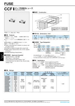
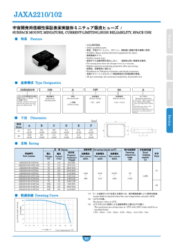
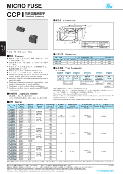
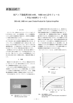
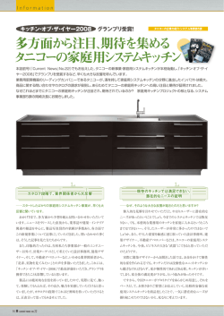
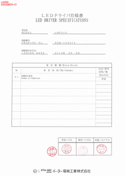
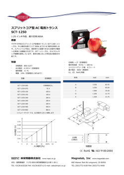
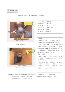
FUSE
CCF
EU
RoHS
チップ形電流ヒューズ
Chip Current Fuses
■構造図 Construction
①
c
L
②
c
③
Fuses
ヒューズ
t
① セラミックケース Ceramic case
② ヒューズエレメント Fuse element
③ 電極キャップ Electrode cap
W
外装色:白 Body color:White
■外形寸法 Dimensions(mm)
■特長 Features
面実装タイプの一次回路、二次回路に使用できる
電流ヒューズです。
● セラミックボディのため機械強度に優れています。
● 独自の製法により溶断特性が安定しています。
● 耐サージ性に優れています。
● リフロー、フローはんだ付けに対応します。
● 端子鉛フリー品は、欧州RoHS対応品です。
● Surface mounting fuses suitable for primary and
secondary circuits.
● Excellent mechanical strength with ceramic body.
● Stable fusing characteristics due to the original
technology.
● Excellent Anti-Surge characteristics.
● Suitable for reflow and flow soldering.
● Products with lead free termination meet EU-RoHS
requirements.
●
■取得規格 Approvals Awarded
電気用品安全法(1〜10A)B種
PSE(1〜10A)Class B
UL248.14 File No.E171861(250mA〜15A)
c-UL(CSA)C22.2 No.248.14 File No.E171861
(250mA〜15A)
寸 法 Dimensions(mm)
形 名
Type
L±0.2
W±0.2
t±0.2
c±0.2
Weight(g)
(1000pcs)
CCF1N
6.0
2.5
2.5
1.4
140
■品名構成 Type Designation
例 Example
CCF
1
N
1
品 種
Product
Code
形 状
Style
溶断特性
Fusing
Characteristics
定格電流
Rated
Current
N:普通溶断
N:Normal blow
T
TE
定格電圧(UL) 端子表面材質
Rated
Terminal
Voltage(UL) Surface Material
二次加工
Taping
空欄 Nil:
T : Sn
125Va.c./60Vd.c. (Nil : Sn/Pb)
or 65Va.c./65Vd.c.
D:125Va.c./160Vd.c.
TE:4mm pitch
plastic
embossed
BK:Bulk
端子表面材質は鉛フリーめっき品が標準となります。
環境負荷物質含有についてEU-RoHS以外の物質に対するご要求がある場合にはお問合せください。
テーピングの詳細については巻末のAPPENDIX Cを参照してください。
The terminal surface material lead free is standard.
Contact us when you have control request for environmental hazardous material other than the
substance specified by EU-RoHS.
For further information on taping, please refer to APPENDIX C on the back pages.
■用途 Applications
●
●
●
●
●
ノートパソコン用電源 Power supplies for note PCs
液晶インバータ電源
Power supplies for LCD inverters
照明用インバータ電源 Power supplies for Illumination inverters
複写機、LBP
Copying machines, Laser beam printers
産業用機器
Industrial equipment
■定格 Ratings
形 名
Type
定格電流
Rated
Current
定格電圧
Rated
Voltage
遮断容量
Interrupting
Capacity
CCF1N0.4
CCF1N0.5
CCF1N0.63
CCF1N0.8
CCF1N1
CCF1N1.25
CCF1N1.6
CCF1N2
CCF1N2.5
CCF1N3.15
CCF1N4
CCF1N5
CCF1N6.3
CCF1N7
CCF1N8
CCF1N10
CCF1N12
400mA
500mA
630mA
800mA
1A
1.25A
1.6A
2A
2.5A
3.15A
4A
5A
6.3A
7A
8A
10A
12A
UL (c-UL)
AC 125V
DC 60V
(DC 160V)
UL (c-UL)
AC 125V 50A
DC 60V 50A
(DC 160V)
電安法
PSE
AC 100V
CCF1N15
15A
溶 断 特 性
Fusing Characteristics
定格電流
溶断時間
Rated Current Fusing Time
UL (c-UL)
100%
200%
4h Min.
1s Max.
電安法 PSE
AC 100V 100A
電安法 PSE
130%
160%
200%
4h Min.
1h Max.
1s Max.
UL (c-UL)
AC 125V
DC 60V
UL (c-UL)
AC 125V 50A
DC 60V 50A
UL (c-UL)
100%
200%
4h Min.
1s Max.
(DC 160V)
(DC 160V)
UL (c-UL)
AC 65V
DC 65V
UL (c-UL)
AC 65V 50A
DC 65V 50A
UL (c-UL)
100%
200%
4h Min.
60s Max.
内部抵抗値 公称溶断I t値 テーピングと包装数/リール
Internal R. Normal Melting Taping & Q'ty/Reel (pcs)
I2t(A2・s)
(mΩ)
Max.
TE
2
650
510
390
250
90.4
75.9
59.3
42.9
36.6
26.0
20.1
15.3
11.4
10.6
9.5
7.5
4.5
3.5
0.024
0.030
0.052
0.125
0.156
0.220
0.513
0.814
1.31
2.37
3.85
6.5
10.6
12.8
17.0
27.7
73.5
1,000
125.5
使用温度範囲:−55℃〜+125℃
Operating Temp. Range:−55℃〜+125℃
本カタログに掲載の仕様は予告なく変更する場合があります。ご注文およびご使用前に納入仕様書で内容をご確認ください。
車載機器、医療機器、航空機器など人命に関わったり、あるいは甚大な損害を引き起こす可能性のある機器へのご使用を検討される場合には、必ず事前にご相談ください。
Specifications given herein may be changed at any time without prior notice. Please confirm technical specifications before you order and/or use.
Contact our sales representatives before you use our products for applications including automotives, medical equipment and aerospace equipment.
Malfunction or failure of the products in such applications may cause loss of human life or serious damage.
Oct. 2011
www.koanet.co.jp
■ディレーティング Deratings
定常ディレーティング Normal derating
本製品の定常ディレーティングは0.7以下が基準となります。
Normal derating of this product should be 0.7max. as standards.
● 温度ディレーティング Deratings by ambient temperatures
常温(25℃±5℃)以外の周囲温度で使用する場合には、
温度補正が必要となり右図のディレーティング係数を考慮ください。
When using the products at the temperatures other than normal
temperature (25℃±5℃), temperature adjustment will be required.
Please refer to the derating coefficient as shown in the figure.
ディレーティング係数
Derating coefficient
●
1.5
1.4
1.3
1.2
1.1
1.0
0.9
0.8
0.7
0.6
0.5
-55
-35
-15
5
25
45
65
85
105
125
周囲温度 Ambient temperature(℃)
15
12
5
6.3
7
8
10
3.15
4
1.6
2
2.5
1.25
1
Fuses
ヒューズ
10
0.8
0.4
0.5
0.63
■溶断特性 Fusing Characteristic
15
10
2
2.5
3.15
4
5
6.3
8
10
0.8
1
1.25
1.6
0.1
0.4
0.5
0.63
溶断時間 Fusing Time(s)
1
0.01
溶断時間(sec)
Fusing time
1
0.001
0.1
1
10
100
1000
溶断電流 Fusing Current(A)
■性能 Performance
規格値 Performance Requirements
ΔR±%
試験項目
Test Items
溶断特性
Fusing characteristics
表面温度上昇
Surface Temp. Rise
0.1
10
1
保証値 Limit
代表値 Typical
試験方法
Test Methods
0.01
規定の時間内溶断後の絶縁抵抗は0.2MΩ以上
—
Within specified time. No restrike
定格電流値の160%、200%の電流を通電して溶断するまでの時間を測定
Fusing time measured under rated current×160% and×200%.
温度上昇140℃以下
Max. Temp. Rise 140℃
定格電流値の115%を通電時のケース表面温度
Surface Temp. should be measured by Rated current×115%.
可溶体の断線及びケースに破損のないこと。
—
No mechanical damage.
定格電流値の100%を通電時のケース表面温度
Surface Temp. should be measured by Rated current×100%.
1
10
100
支持点間隔90mm、曲げ幅3mm、1回
溶断電流 Fusing current(A)
Distance between holding points 90mm, Bending width 3mm, 1time.
はんだ耐熱性
Resistance to soldering heat
10
260℃±5℃, 10s±0.5s
はんだ付け性
Solderability
95%以上が新しいはんだで覆われること。
—
95% coverage min.
235℃±5℃, 3s±0.5s
10
5
70℃±2℃、1000h、定格電流×70%、1.5時間ON/0.5時間OFFの周期
Rated current×70%, 1.5h ON / 0.5h OFF cycle
10
5
40℃±2℃、90%〜95%RH、1000h、定格電流×70%、1.5時間ON/0.5時間OFFの周期
Rated current×70%, 1.5h ON / 0.5h OFF cycle
電極強度
Bending test
0.1
0.01
通電寿命
Load life
耐湿通電寿命
Load life moisture
0.001
0.1
温度上昇75℃以下
Max. Temp. Rise 75℃
—
温度急変
10
Rapid change of temperature
—0.001
0.1
3
1
10
5
100
1000
−55℃(30min)/+125℃(30min)100 cycles
■使用上の注意 Precautions for Use
●
●
●
●
●
●
本
(硫化水素、亜硫酸ガス、塩化水素等)、ほこり等の無い環境としてください。は
製品の保管、ご使用に関しましては、結露、有毒ガス
んだ付性の低下、断線の発生があります。
本
製品は温度による影響を受けますので、ご使用前に貴社製品に実装した状態で温度上昇(△t=50℃以下)及び異常電流での回路遮断
の評価、ご確認をお願いします。
本カタログ内の「ヒューズの使用上の注意事項」も合わせてご確認ください。
Store and use CCF products in dust-free room avoiding dew condensation, corrosive gas (H2S, SO2, HCℓ gas), etc. Otherwise the products
are more likely to have lower solderability and fusing.
High temperature affects on the product's performances. After mounting the products on your applications, be sure that the maximum
temperature rise is 50 degrees or below and that if the circuit is interrupted or not under abnormal current.
Please also confirm“precautions for use of fusing components”in this catalogue.
本カタログに掲載の仕様は予告なく変更する場合があります。ご注文およびご使用前に納入仕様書で内容をご確認ください。
車載機器、医療機器、航空機器など人命に関わったり、あるいは甚大な損害を引き起こす可能性のある機器へのご使用を検討される場合には、必ず事前にご相談ください。
Specifications given herein may be changed at any time without prior notice. Please confirm technical specifications before you order and/or use.
Contact our sales representatives before you use our products for applications including automotives, medical equipment and aerospace equipment.
Malfunction or failure of the products in such applications may cause loss of human life or serious damage.
Oct. 2011
www.koanet.co.jp
© Copyright 2026 Paperzz