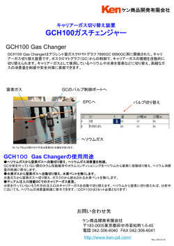
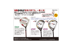
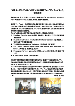
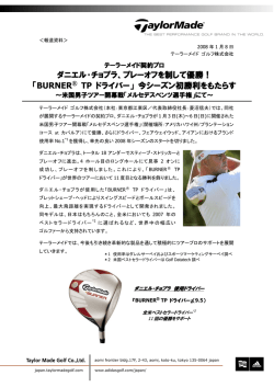
コージェネレーションシステム用追い焚きバーナ
BURNER FOR CO-GENERATION SYSTEM
コージェネレーションシステムの熱供給の一つの方式として、蒸気需要
量がその利用可能保有熱を上回る場合、追い焚きシステムが採用さ
れます。このシステムは追い焚きバーナによってガスタービン高温排ガ
スをさらに加熱することにより、蒸気発生能力を増大するものです。この
システムは、
ガスタービン排ガス中の余分な酸素のみで燃焼するため省
エネルギーであることや、
また1000℃近い高温排ガスが得られるため、
廃熱ボイラーの伝熱面積の些かな増加で多量の蒸気を得ることがで
きるなどのメリットがあります。
本追い焚きバーナはNOxの発生が少なく、ボイラー用バーナとして不
可欠な広いターンダウン比を持つなどの特長を持っています。
(大阪ガスとの共同開発)
If the demand for steam exceeds its available potential heat,
the reheating system is adopted as one method of heat supply
of the cogeneration system. This system increases steam
generating capacity by further heating gas turbine hightemperature exhaust gas using the reheating burner.
In this system, energy can be saved because of combustion
with only extra oxygen in gas turbine exhaust gas and hightemperature exhaust gas (nearly 1,000℃) can be obtained.
Therefore, the system has the advantage that a large amount
of steam can be generated by a slight increase in heat
transmission area of the waste heat boiler. The reheating
burner has the features that only a very small amount of NOx
and a wide turn-down ratio essential for the boiler burner. (Joint
development with Osaka Gas Co., Ltd.)
1.追い焚きシステム
2.バーナ構造
通常ガスタービン排ガスは廃熱ボイラーにより、蒸気として熱回収
されますが、追い焚きを行わないシンプルシステムと、
より多くの蒸
気を発生させる追い焚きシステムがあります。通常ガスタービン排
ガスの温度は450∼550℃、酸素濃度は13∼16%であり、追い焚
きシステムはこのガスタービン排ガスを燃焼空気として使用します。
バーナはタービン排ガスのダクト幅にわたってバーナユニットをライ
ン状に連結し、
ガスノズルから噴出したガスは、
その流速でガスター
ビン排ガスの一部をウイングノズルから吸引し、着火に必要な酸素
が取り込まれた後、
ウイング内部で安定保炎されます。燃焼はガス
タービン排ガスと順次混合しながら継続し、廃熱ボイラーに至るま
でに完結します。
1. Reheating system
Usually, heat of gas turbine exhaust gas is recovered as
steam by the waste heat boiler, and there are two systems:
a simple system without reheating and a reheating system
that generates more steam. Usually, the temperature of
gas turbine exhaust gas is 450 - 550℃ and the oxygen
concentration is 13 - 16%, and the reheating system uses
this gas turbine exhaust gas as combustion air.
ガス
ービ
Gas タ
turbin ン
e
ガス Gas
発
エア
Gene電機
燃焼器
rator Air
Combustor
2. Burner structure
The burner unit is connected with the duct of turbine
exhaust gas along with the duct width and on the line, and
gas blown out from the gas nozzle suctions some of the
gas turbine exhaust gas from the wing nozzle at its speed.
After oxygen necessary for ignition is taken in, stable flame
is held in the wing. Combustion sequentially continues to
mix with gas turbine exhaust gas and completes before
reaching the waste heat boiler.
排ガス
Exhaust gas
タービン排ガス
Turbine exhaust gas
追い焚きバーナ
Reheating burner
温水分離ドラム
Hot water
separation drum
エコ
Econノマイザ
omiz
er
圧縮機 タービン
Compressor
電力
Turbine
Electricity
廃熱
ボイラ
Waste
heat
boiler
ガス
Gas
火炎
Flame
給水
Water
su
pply
ガスノズル
Gas nozzle
ウイングノズル
Wing nozzle
バーナウイング
Burner wing
追い焚きバーナ 1/2ユニット
(1/2ft)
Reheating burner
中外炉工業株式会社
コージェネレーションシステム用追い焚きバーナ
152.5
BURNER FOR CO-GENERATION SYSTEM
特長
FEATURES
1. 低NOx
ガスタービン排ガス条件(GT4/4負荷時)
Gas turbine exhaust gas conditions (under GT 4/4 load)
100
60
▲
▲ 3/4
2/4
▲
▲
40
▲
80
GT負荷
GT load
4/4
▲
追い焚きバーナNOx(ppm.0%)
Water injection rate
Reheating burner NOx (ppm.0%)
水噴射率
Qc=29,250m3/h(normal)
Tc=497℃
O2=13.1(%wet)
14.5(%dry)
W/F=0.75(g/g)
▲
The burner has its structure to control combustion in the
wing as much as possible and completes most of
combustion outside the wing with exhaust gas that flows
from the periphery of the wing. This structure provides a
gradual combustion on the wing wake side to make NOx
low (Fig. 1 shows NOx characteristics by the result of
combustion on the actual equipment).
Flow rate
Temperature
Oxygen concentration
▲
1. Low NOx
流 量
温 度
酸素濃度
▲
バーナはウイング内での燃焼を極力抑制し、
ウイングの周りから巻
き込まれる排ガスによって大半の燃焼をウイング外で完結する構
造になっています。この構造によりウイング後流側で緩慢燃焼する
ため低NOxとなります。
(図1は実機での燃焼結果によるNOx特性を示します。)
▲
▲
▲
20
0
0
100
200
300
400
500
600
追い焚きバーナ×11.63kW(×104kcal/h)
GTのみ Reheating burner ×11.63kW(×104kcal/h)
Only GT
図1追い焼きバーナのNOx特性
Fig. 1: NOx characteristics of reheating burner
2. 燃焼用エアブロワが不要
2. Air blower for combustion is unnecessary.
低酸素濃度中(タービン排ガスを燃焼用エアとする)で完全燃焼
しますので、外部からのエアを供給する必要がありません。
As fuel is completely combusted at a low oxygen
concentration (air for combustion is turbine exhaust gas), it
is unnecessary to supply air from the outside.
3. 広い調節範囲
3. Wide adjustment range
追い焚きバーナはボイラー用バーナの一種とみなされるため、蒸気
負荷に追随して、広い燃料の絞り比(ターンダウン比)が要求され
ます。
バーナは、低燃焼から高燃焼まで安定かつ良好燃焼が得られる構
造により10:1の広いターンダウン比が得られます。
As a reheating burner is considered as a kind of burner for
a boiler, a wide drawing ratio (turn-down ratio) of fuel is
required along with steam load. The burner can obtain a
wide turn-down ratio of 10:1 by its structure that enables
stable and good combustion (from low combustion to high
combustion).
4. 省エネルギー
追い焚きシステムは、追い焚きを行わないシステムに比べて、ボイ
ラー効率が向上します。これは給水量の増加により、排ガス温度
が低下するためです。
4. Energy saving
The boiler efficiency increases on a reheating system
compared with a system without reheating. This is because
an increase in water supply quantity lowers the exhaust gas
temperature (Fig. 2 shows the performance by adoption of
a reheating system).
100
ボイラー効率
Boiler efficiency
90
80
15.0
蒸気量
Steam amount
10.0
5.0
70
エコノマイザー出口
排ガス温度
Economizer outlet
Exhaust gas temperature
100
200
300
400
500
160
150
140
130
120
110
600
効率(%)
Efficiency
20.0
給水温度
Feed-water temperature
GT負荷
GT load
気 温
Ambient temperature
82∼125℃
4/4
26∼28℃
エコノマイザー出口
排ガス温度 (℃)
Economizer outlet
Exhaust gas temperature
換算蒸気量(t/h)
Converted steam amount (t/h)
(図2は追い焚きシステムを採用することによる性能を示します。)
追い焚きバーナ燃焼量×11.63kW(×10 kcal/h)
Reheating burner firing rate ×11.63kW (×104kcal/h)
4
図2 追い焚きシステムの性能
Fig. 2: Performance of reheating system
コージェネレーションシステム用追い焚きバーナ
中外炉工業株式会社
BURNER FOR
CO-GENERATION SYSTEM
5. 経済性
5. Economic efficiency
追い焚きシステムの経済性をケーススタディすると下記のように
なります。条件として、4000kWのコージェネレーションシステム
で25t/h,1.3MPa(13.5㎏/cm2)の飽和蒸気が必要なケース
において図3と図4のシステムを比較します。
A case study of economic efficiency of the reheating system is
as follows: As a condition, the systems of Fig. 3 and Fig. 4 are
compared in the case where saturated steam of 25t/h,
1.3MPa(13.5kg/cm2) is required on the co-generation system
of 4,000kW.
廃熱
ボイラー
Waste heat boiler
エア
Air
給水
ガス Gas 952m3/h(normal)
蒸気
Steam
25t/h
給水
Water supply
ガス Gas
廃熱ボイラー
Waste heat boiler
総合ボイラー効率
Waste heat boiler
efficiency
83%
総合ボイラー効率
Waste heat boiler
efficiency
90%
エア
Air
15t/h
蒸気
Steam
15t/h焚きボイラー
ガス Gas
824m3/h(normal)
ボイラー効率 Boiler efficiency 92%
図4 追い焚きシステム
Fig. 4 Reheating system
図3 シンプルシステム+15t/h焚きボイラー
Fig. 3: Simple system + 15t/h heating boiler
ケース
追い焚きなし
No reheating
追い焚きあり
Reheating
Case
設備内容 Equipment content
10t/h廃熱ボイラー+15t/hボイラー
廃熱ボイラー+ボイラー
10t/h waste heat boiler +
15t/h boiler
Waste heat boiler + boiler
25t/h廃熱ボイラー
25t/h waste heat boiler
廃熱ボイラー+追い焚きバーナ
Waste heat boiler +
reheating burner
ランニングコスト Running cost
廃熱ボイラー効率 70%
総合効率83%
ボイラー効率 92%
Waste heat boiler efficiency 70%,
boiler efficiency 92%, total efficiency 83%
廃熱ボイラー効率 90%
Waste heat boiler efficiency 90%
8%省エネルギー
上記はランニングコストのみの比較をしています。
蒸気 Steam
25t/h
8% energy saving
Only running costs are compared in the above.
6. 空気での燃焼が可能
ガスタービン定期点検等のタービン停止時に、
プロセス蒸気が必
要な場合、空気ブロワを別置きすることにより追い焚きバーナで燃
焼を行って蒸気を得るシステムも可能です。
(図5はその一例を示します。)
6. Combustion with air is possible
廃熱ボイラー
Waste heat boiler
If process steam is necessary when a gas turbine is
stopped for gas turbine periodic inspection, etc., the system
to combust fuel with a reheating burner by separately
mounting an air blower to generate steam is also available
(Fig. 5 shows an example of this system).
ガスタービン発電機
ガス
Gas
蒸気
Steam
10t/h
Gas turbine power plant
給水
Water supply
追い焚きバーナ
Reheating
burner
押込ファン
Push-in fan
図5 空気での燃焼システム例
Fig. 5: Example of system of combustion with air
追い焚きバーナ構造図(DLG-6-240)
STRUCTURAL DRAWING OF REHEATING BURNER (DLG-6-240)
排ガス入口
火炎監視装置
Flame detector
Exhaust gas
inlet
火炎監視装置
Flame detector
パイロットバーナ
Pilot burner
燃料ガス入口
Fuel gas inlet
中外炉工業株式会社
コージェネレーションシステム用追い焚きバーナ
BURNER FOR CO-GENERATION SYSTEM
排ガス出口
Exhaust gas
outlet
標準仕様
STANDARD SPECIFICATIONS
1. 燃焼量:MAX465kW/ft(40×104kcal/ft/h)
2. 燃料圧力:0.04MPa at バーナ差圧
3. ターンダウン比:10:1
4. バーナ部でのTEG 注1)差圧:300Pa∼ 注2)
5. 最小TEG量:40m3/h(normal) at 追い焚き量11.63kW(104kcal/h)
6. バーナ入口TEG温度:300∼550℃
注3), 4)
7. バーナ入口TEG酸素濃度:18∼13% at Wetベース
8. バーナ出口排ガス温度:1050℃以下(但し断熱壁の場合)
:(廃熱ボイラー入口排ガス温度)
9. バーナ入口TEGダクト流速:10∼15m/s at 仕様温度・圧力
10. ダクト断面積当り燃焼量:2.33∼4.65MW/m2(200×104∼400×104kcal/m2・h)
11. 材質 ウイング:SUS310S(TEG温度が高温の場合はMA-23) ガスヘッダー:SUS304
12. 火炎長:3m以下
13. TEG整流板差圧:300Pa
注1)TEG:タービン排ガス
注2)ソロノックスタイプのガスタービンを使用する場合のTEG差圧は500Pa必要です。
注3)タービン負荷が下がると温度が下がり、酸素濃度は高くなります。
注4)単独エアモード
(常温空気燃焼)
での追焚きバーナも取扱っております。
1. Firing rate : MAX465kW/ft (40×104kcal/ft/h)
2. Fuel pressure : 0.04MPa at burner differential pressure
3. Turn-down ratio : 10:1
4. TEG differential pressure of burner Note.1) section : 300Pa- Note.2)
5. Minimum TEG amount : 40m3/h (normal)
at reheating amount 11.63kW (104kcal/h)
6. Burner inlet TEG temperature : 300 - 500℃
Note.3, 4)
7. Burner inlet TEG oxygen concentration: 18 - 13% at Wet base
8. Burner outlet exhaust gas temperature : 1050℃ or lower (However, in the case of adiabatic wall)
: (waste heat boiler inlet exhaust gas temperature)
9. Burner inlet TEG duct flow speed : 10 - 15m/s at specification temperature/pressure
10. Firing rate per duct cross-section : 2.33∼4.65MW/m2 (200×104∼400×104kcal/m2・h)
11. Material wing : SUS310S (MA-23, if TEG temperature is high) Gas header : SUS304
12. Flame length : 3m or less
13. TEG current plate differential pressure : 300Pa
Note 1) TEG: turbine exhaust gas
Note 2) TEG differential pressure of 500Pa is required if Solo-NOx type gas turbine is used.
Note 3) When turbine load decreases, the temperature drops and the oxygen concentration becomes higher.
Note 4) Also a reheating burner in the single air mode (air combustion at normal temperature) is available.
燃焼量
FIRING RATE
型式 Model
燃焼容量 MW
Combustion capacity
DLGー6ー240
DLGー8ー320
DLGー10ー400
DLGー16ー640
DLGー22ー800
DLGー28ー1120
DLGー40ー1600
DLGー55ー2200
2.79
3.72
4.65
7.44
9.30
13.0
18.6
25.6
取付寸法
MOUNTING DIMENSIONS
A
単位 Unit (mm)
排ガス入口
B
Exhaust gas
inlet
排ガス出口
Exhaust gas
outlet
型式 Model
DLGー 6ー 240
DLGー 8ー 320
DLGー10ー 400
DLGー16ー 640
DLGー22ー 800
DLGー28ー1120
DLGー40ー1600
DLGー55ー2200
A
622
927
1232
1232
1232
1232
1232
1842
B
559
559
559
864
1169
1549
2234
2234
※ダクト寸法はタービン排ガス量で決まりますので
別途ご相談ください。
※As duct dimensions are determined
by turbine exhaust gas capacity,
contact us separately.
コージェネレーションシステム用追い焚きバーナ
中外炉工業株式会社
BURNER FOR
CO-GENERATION SYSTEM
バーナフローシート
BURNER FLOW SHEET
NO.2
25A
15A
15A
15A
65A
バーナの出口ダクトは客先手配品
Burner outlet duct is a
component arranged
by the customer.
パージエア 25A
パイロットエア 25A
パイロットガス 15A
メインガス 65A
15A
8A
50A
32A
8A
15A
Open
Close
8A
50A
50A
20A
ベント
Vent
P=0.5MPa(5kg/cm2)
T=20℃
50A
NO.3 NO.4
A
15
屋外ケース Outdoor case
DC
4∼20mA
15A
AC110V60Hz 1φ
DC
4∼20mA
ガス燃料
Gas fuel
排ガス Exhaust gas
タービン排ガス
Turbine exhaust
gas
NO.1
25A
25A
追い焚きバーナ盤
Reheating
burner panel
DC4∼20mA
計装空気
Instrumentation air
15A
FICより From FIC
AC110V60Hz1φ
低圧補機盤より
From Low-pressure auxiliary panel
AC220V 60Hz 3φ
15A
8A
Open
32A
Purge air 25A
Pilot air 25A
Pilot gas 15A
Main gas 65A
Close
25A
65A
メインガス
Main gas
15A
パイロットガス
Pilot gas
50A
25A
15A
P=0.5MPa(5kg/cm2)
T=10∼25℃
Q=780m3/h(normal)
15A
15A
15A
AC220V60Hz 3φ
AC220V60Hz 3φ
L
25A
パイロットエア
Pilot air
25A
パージエア
Purge air
32A
配管ユニット
PIPING UNIT
DLGー22ー800型追い焚きバーナ
ユニット寸法例:
(2900W×2100H×1000D)
中外炉工業株式会社
コージェネレーションシステム用追い焚きバーナ
DLG-22-800 reheating burner
Example of unit dimensions : (2900W×2100H×1000D)
BURNER FOR CO-GENERATION SYSTEM
※掲載製品には特許取得済・申請中の技術が含まれています。
*The equipments in this catalog include patented /
patent pending technologies.
※ 本カタログはSI単位を採用しています。
従来単位とは下記数式にて換算してください。
*This catalog uses the SI units which can be calculated from the following
formula:
●1kcal/h=1.163×10-3kW 1kW=860kcal/h ●1kcal=4.18kJ(10000kcal=41.8MJ) 1kJ=0.239kcal(1MJ=239kcal) ●1mmH2O=1kg/m2=9.81Pa(1kg/㎝2=98.1kPa)
1Pa=0.102mmH2O(1kPa=102mmH2O)
安全に関するご注意:
ご使用の際は、取扱説明書をよくお読みの上、正しくお使いください。
SAFETY PRECAUTIONS :
Read the instruction manual carefully before using the equipment.
URL http://www.chugai.co.jp
堺 事 業 所 〒592-8331 堺市西区築港新町2丁4番
(072)247-1440
(直通) FAX
(072)247-1441
サーモシステム事業部 TEL
Sakai Works : 2-4,Chikko-Shinmachi,Nishi-ku,Sakai 592-8331,Japan
Tel +81-72-247-1440 Fax +81-72-247-1441
東 京 支 社 〒108-0075 東京都港区港南2丁目5番7号(港南ビル)
サーモシステム事業部 TEL(03)5783-3378(直通) FAX(03)5783-3368
Tokyo Branch : 2-5-7,Konan,Minato-ku,Tokyo 108-0075,Japan
Tel +81-3-5783-3378 Fax +81-3-5783-3368
名古屋営業所 〒450-0003 名古屋市中村区名駅南1丁目21番19号(本州名駅ビル)
TEL(052)561-3561(代表) FAX
(052)561-3566
Nagoya Sales Office: 1-21-19,Meieki-Minami,Nakamura-ku,Nagoya 450-0003,Japan
Tel +81-52-561-3561 Fax +81-52-561-3566
燃 焼 研 究 所 〒582-0027 大阪府柏原市円明町1000番地6
TEL(072)977-8503(代表) FAX(072)978-6981
Combustion Laboratory: 1000-6,Enmyo-cho,Kashiwara,Osaka 582-0027,Japan
Tel +81-72-977-8503 Fax +81-72-978-6981
●記載内容について、改良のため予告なしに変更する場合もありますので、あらかじめご了承ください。
●The descriptions and specifications are subject to change without notice.
140205(M)
© Copyright 2026 Paperzz