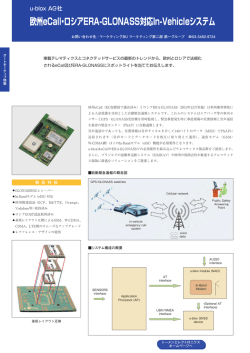
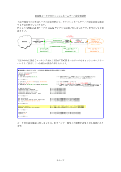
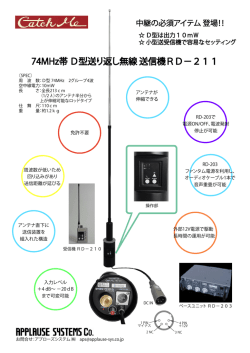
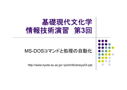
ASAHI KASEI [AK4571] AK4571 特長: USB オーディオコントローラ内蔵 12 Mbps bit rate USB Serial Interface Engine(SIE) Audio Class Processing Block 4 Endpoints USB transceiver 16 bit codec - A/D Converter 1 channel for Microphone Pre-Amp (Fixed Gain: 20dB) Mute/Volume Control Programmable Gain Control +24dB to –31dB ( 1dB step ) - D/A Converter 2 channel - Mixer Mute/Attenuation Control +0dB to –47dB ( 1dB step ) Analog Bass Boost HID Support 手元で再生用ボリューム・ミュート制御可能 録音用ミュート&ステータス Power Management 外部ヘッドフォンアンプ制御 EEPROM Interface (Micrpwore Type) - Descriptorを外部EEPROMよりリード可能 - 1K/2K/4K bit EEPROM対応 On-chip PLL 7 周波数対応: 8kHz, 11.025kHz, 16kHz, 22.05kHz, 32kHz, 44.1kHz, 48kHz USB I/F 内蔵 Audio CODEC 概要: AK4571は 1ch A/D コンバータと、2ch D/Aコンバータを内蔵する1 チップ16bit CODECです。AK4571はUSB I/Fを持ち、USBバスを介 してデータの転送を行います。一つの水晶で、7種類のサンプリング 周波数を設定できると共に、ADC、DACそれぞれ独立に動作可能 です。このためのPLLや、トランシーバ、SIE(Serial Interface Engine)、オーディオ制御回路、FIFO等は全て内蔵しています。 アナログ入力は、初段20dB固定アンプを持つと共に、+24dBから -31dBまで1dB毎に可変可能なゲインアンプを持っています。さらに、 アナログ入力は、D/A出力とミキシングし、アナログ出力することが 可能です。 アナログ出力は、0dB∼-43dBまで1dB幅のアッテネータを持つと 共に、アナログバスブースト回路を内蔵しています。外部に抵抗とコ ンデンサを接続することで、任意のゲイン・カットオフ周波数を設定 することが可能です。 AK4571はHID機能を持ち、手元で再生用ボリューム・ミュートを制 御することが可能です。また、手元でアナログ入力をミュートするこ とも可能です。 AK4571は、高機能なパワーマネージメント機能を持っています。サ スペンド時、AK4571の消費電流は、1uA未満です。また、外部ヘッ ドフォンアンプの制御機能を持つため、USBの要求仕様である、シ ステムとして500uA未満を満たすことが可能です。 また、Microwire型のEEPROM I/Fを持ち、Vendor IDや、Product ID等をカスタマイズすることが可能です。 AK4571は、レギュレータ、水晶、ヘッドフォンアンプの主要コンポー ネントのみで、USB ヘッドフォンを実現することが可能です。 Single Power Supply, Low Power +3.3Volts±0.3V Package 48pin LQFP MS0153-J-03 2005/06 -1- ASAHI KASEI [AK4571] ブロックダイアグラム VA AGND BGND STBY CS RBFI M M Bass Boost Bass Boost EPDO EPAI SK EPEN EEPROM I/F Power Management EPSW EMSW RBFO LOUT INC VREF MICBIAS ROUT VRAD VRDA MSTAT IMUTE OMUTE DEC DGND VD VCOM Config ROM Master volume Mixer ATT Σ ATT DAC String ROM FIFO DAC Σ EPSEL FIFO Audio Control Block USB Serial Interface Engine USB Transceiver DP DN LBFI LBFO GAIN MICIN 20dB M ADC GAIN AMP1O AMP2I M FIFO PLL AMP2O LFLT_44K LFLT_48K LFLT_SYS XTLIN PLL1 XTLOUT RSTN CRYSTAL MS0153-J-03 2005/06 -2- ASAHI KASEI [AK4571] オーダリングガイド AK4571VQ AKD4571 0 ∼ +70°C 48pinLQFP(0.5mm ピッチ) AK4571評価ボード ピン配置 40 EPSEL 35 DGND BGND XTALOUT XTALIN TEST2 45 1 TEST1 IMUTE MSTAT INC DEC OMUTE RSTN SUSN DP DN TEST3 VD EPDI EPAO SK 5 CS EPSW STBY 30 EMSW LFLT_SYS LFLT_44K LFLT_48K VCOM EPEN TESTMODE3 TESTMODE2 VRDA 10 VRAD 25 20 15 ROUT RBFO RBFI LOUT LBFO LBFI TESTMODE1 AMP2O AMP2I AMP1O MICIN MICBIAS MS0153-J-03 AGND VA 2005/06 -3- ASAHI KASEI [AK4571] ピン/機能 No. Signal Name USB Interface 46 DP I/O Ana / Dig I/O D USB bus Non-Inverting pin. Since the AK4571 is a full-speed device, a 1.5kΩ resistor must be connected between D+ node to VD. 47 DN Reset, Crystal, PLL 45 RSTN I/O D USB bus Inverting Pin. I D Reset Pin. Low input resets the chip. Schmitt Trigger input. Suspend Pin "L": Suspend Mode “H”: Normal Mode Crystal Oscillator Output, Connect Crystal Resonator. Connect capacitor Crystal Oscillator Input, Connect Crystal Resonator. Connect capacitor System PLL loop filter Pin. Connect 2.7kΩ resistor and 22nF capacitor in series externally. Codec PLL loop filter Pin. Connect 120kΩ resistor and 6.8nF capacitor in series externally. Codec PLL loop filter Pin. Connect 120kΩ resistor and 6.8nF capacitor in series externally. 44 SUSN O D 4 5 9 XTALOUT XTALIN LFLT_SYS O I O A A A 10 LFLT_44K O A 11 LFLT_48K O A O O O I O I O A A A A A A A O O I O I O O A A A A A A A Analog Input/Output 12 VCOM 27 VRAD 28 VRDA 14 MICIN 15 AMP1O 16 AMP2I 17 AMP2O 21 24 19 20 22 23 13 LOUT ROUT LBFI LBFO RBFI RBFO MICBIAS External Headphone Amplifier Control 6 EPSW O 7 STBY O 8 EMSW O Description Analog Common Voltage Reference Pin ADC Common Voltage Reference Pin. ADC Common Voltage Reference Pin. Mono Channel Microphone Input Mono Channel 1st Amplifier Output Pin Mono Channel 2nd Amplifier Input Pin Mono Channel 2nd Amplifier Output Pin Please Connect 1nF capacitor. Left Channel D/A Out Right Channel D/A Out Left Channel Bass Boost Filter Input Pin Left Channel Bass Boost Filter Output Pin Right Channel Bass Boost Filter Input Pin Right Channel Bass Boost Filter Input Pin Voltage Reference Output for the Microphone’s bias voltage When the chip goes into Suspend mode, this pin goes to Hi-Z. External Headphone Amplifier Power Switch Control Pin 1 “H”: Normal Operation “L”: Suspend Mode External Headphone Amplifier Power Switch Control Pin 2 “L”: Normal Operation “H”: Suspend Mode External Headphone Amplifier Mute Control Pin “H”: MUTE ON “L”: MUTE OFF MS0153-J-03 2005/06 -4- ASAHI KASEI [AK4571] No. Signal Name EEPROM I/F I/O Ana / Dig Description 31 CS O D EEPROM I/F Chip Select Pin 32 SK O D Read Clock Pin 34 EPDI I D EEPROM Data Input Pin 33 EPAO O D EEPROM Address Output Pin 35 EPEN I D 36 EPSEL I D EEPROM Enable Pin "H": Read Device/String Descriptor from external EEPROM ”L”: Read Device/String Descriptor from internal ROM. CS,SK,EPDI,EPAO are Hi-Z EEPROM Select “L”: 1Kbit Type EEPROM is connected. “H”: 2Kbit/4Kbit EEPROM is connected HID Interface 39 IMUTE I D 43 OMUTE I D 41 INC I D 42 DEC I D 40 MSTAT O D P P P P P A A D D D Power Supply 25 VA 26 AGND 1 VD 2 DGND 3 BGND Test Mode 18 TESTMODE1 29 TESTMODE2 30 TESTMODE3 38 TEST1 I I I I A/D Mute Toggles mute status at the rising edge. If this pin is not used, please connect this pin to DGND. D/A Mute Sets “1” to internal register at the rising edge, and reset to “0” at the falling edge. If this pin is not used, please connect this pin to DGND. D/A Volume Up Pin Sets “1” to internal register at the rising edge, and reset to “0” at the falling edge. If this pin is not used, please connect this pin to DGND. D/A Volume Down Pin Sets “1” to internal register at the rising edge, and reset to “0” at the falling edge. If this pin is not used, please connect this pin to DGND. Recording Mute Status Pin. “H”: Mute ON “L”: Mute OFF In suspend mode, this pin is “L”. Analog Power Supply, 3.3V Analog Ground Digital Power Supply, 3.3V Digital Ground Bulk Ground, 0V Please tie down to AGND for normal operation. Please tie down to AGND for normal operation. Please tie down to AGND for normal operation. Please tie down to DGND for normal operation. 37 TEST2 O Please open state 48 TEST3 I Please tie down to DGND for normal operation. MS0153-J-03 2005/06 -5- ASAHI KASEI [AK4571] 絶対最大定格 AGND, DGND=0V Parameter Power Supplies Analog Digital |DGND-AGND| Input Current (any pins except for supplies) Analog Input Voltage Digital Input Voltage Ambient Temperature Storage Temperature Note 1. 電圧はすべてグランドピンに対する値です。 Symbol min Max Units VA VD ∆GND IIN VINA VIND Ta Tstg -0.3 -0.3 4.5 4.5 0.3 ±10 VA+0.3 VD+0.3 70 125 V V V mA V V °C °C -0.3 -0.3 0 -40 注意: この値を超えた条件で使用した場合、デバイスを破壊することがあります。 また通常の動作は保証されません。 推奨動作条件 AGND, DGND=0V Parameter Ambient Temperature Power Supplies Analog Digital Symbol Ta min 0 typ Max 70 Units VA VD 3.0 3.0 3.3 3.3 3.6 3.6 V V 注意;本データシートに記載されている条件以外のご使用に関しては、当社では、責任負いかねますので十分ご注意下さい。 MS0153-J-03 2005/06 -6- ASAHI KASEI [AK4571] アナログ特性 Ta=25°C,VA=VD=3.3V, Signal Frequency=1kHz, Sampling Frequency Fs=44.1kHz BW=20Hz – 20kHz, TEST mode; unless otherwise specified Parameter Min typ Max Units Mono ADC (1 channel) Resolution 16 bits S/N (A weight) @44.1kHz 83 dBA (PGA is set to 0dB) AMP2I input : USB Normal mode S/(N+D) (-1.0dB analog input) USB Normal mode 73 dB Full scale input Voltage 0.53 0.6 0.67 Vrms MIC amplifier S/N (A weight) 76 84 dBA MICIN input AMP1O output Gain 20dB Selected +17 +20 +23 dB Input Impedance 10 20 kΩ Stereo DAC (2 channel) Resolution 16 bits S/N (A weight) @44.1kHz (DAC volume &master volume is set to 0dB) 84 dBA USB Normal mode S/(N+D) (-1.0dB digital input) USB Normal mode 75 dB Full scale output Voltage 0.53 0.6 0.67 Vrms PGA Step size 0 1.0 2.0 dB Attenuation control range -31 +24 dB Input Impedance AMP2I input 10 20 kΩ Master volume: step size 0 1.0 2.0 dB Attenuation control range -47 0 dB Output Load Resistance 10 kΩ Output Load Capacitance 5 pF Bass Boost Internal Resistance 40 kΩ External Resistance 360 400 kΩ External Capacitance 5 pF MIC Bias (Buffer Amp) Output Voltage 1.94 2.2 2.46 Vdc Output Current 2 mA Power Supplies mA 52 35 Analog mA 23 15 Digital mA 75 50 Total uA 150 0 Power Down(Suspend) MS0153-J-03 2005/06 -7- ASAHI KASEI [AK4571] フィルタ特性 Ta=25°C, VA=VD=3.3V, fs=44.1kHz Parameter ADC Digital Filter ( Decimation LPF) min typ 0 26.5 70 Pass band (±0.2dB) Stop band Stop band Attenuation Group Delay ADC Digital Filter (HPF) max Units 17.64 kHz kHz dB ms 0.363 Frequency Response: -3dB -0.5dB -0.1dB DAC Digital Filter 6.89 19.3 44.9 0 26.5 70 Pass band (±0.2dB) Stop band Stop band Attenuation Group Delay DAC Analog Post filter Hz 17.64 kHz kHz dB ms - dB 0.312 Pass band Frequency Response - MS0153-J-03 ±0.1 2005/06 -8- ASAHI KASEI [AK4571] ディジタルDC特性 Ta=0 - 70°C; VD=3.0 - 3.6V; DGND=0V Measurement under static state All digital pins except DP, DN. Schmitt hysteresis level of RSTN pin and levels of all test pins will not be tested. Parameter Symbol Min Typ Max EPDI,EPEN, EPSEL, pin “H” level input voltage VIH 70%VD EPDI, EPEN, EPSEL pin “L” level input voltage VIL 30%VD RSTN pin “H” level voltage VIHR 2.4 RSTN pin “L” level voltage VILR 0.8 IMUTE, OMUTE, INC, DEC pin “H” level voltage VIHR 2.4 IMUTE, OMUTE, INC, DEC pin “L” level voltage VILR 0.8 SUSN, EPSW, STBY, EMSW, MSTAT pin VOH 2.4 “H” level output voltage IOH= 2mA SUSN, EPSW, STBY, EMSW, MSTAT pin VOL 0.6 “L” level output voltage IOL= -2mA CS, SK, EPAO pin “H” level output voltage VOH 2.4 IOH= 2mA CS, SK, EPAO pin “L” level output voltage VOL 0.6 IOL= -2mA DP, DN Single Ended Receiver Threshold for “H” level VIHR 2.0 DP, DN Single Ended Receiver Threshold for pin “L” level VILR 0.8 Input Leakage Current Iin ±10 Rpd 100 Pull down Resistance (only EPDI pin)@3.3V Ta=25°C スイッチング特性 Ta=25°C, VA=VD=3.3V Parameter Symbol Min Typ Master Clock Frequency MCLK 12.000 Reset input width @RSTN pin(low active) Wrst 1.0 Time Width for USB Reset Signal Recognition Trst_rec 3.0 DP<VseL & DN< VseL to USB Reset mode Device Ready Time from USB Reset After releasing from USB Reset to Device Ready Tdrr (Transaction can start) Time Width for Suspend Recognition Tsus_rec 4.36 Idle state ( DP > VseL & DN < VseL ) to Suspend mode Resume Time from Suspend First flip of DP/DN from Idle state Tresm To Device Ready*) Imute input width with @IMUTE pin(High active) Wimute 10.005 Omute,Dec,Inc input width with @OMUTE,DEC,INC Wodi 2.001 pin (High active) Device Ready: VREF, X’tal oscillator and PLL are stable and standard bus transactions can proceed MS0153-J-03 Units V V V V V V V V V V V V µA kΩ Max - Units MHz us µs 10 ms ms 30 ms ms ms 2005/06 -9- ASAHI KASEI [AK4571] Trst_rec Tdrr Tsus_rec Tresm resume time recovery time D+ D- Master Clock Figure 1. Mode Change with respect to Bus States トランシーバ/レシーバ特性 Ta=25°C; VD=3.3V; DGND=0V; CL=50pF Parameter Symbol Transmitter Data Rate DR Pins DP,DN Output Impedance (Hi) Roh DP, DN Output Impedance (Lo) Rol DP, DP Vohd Vold Iolk Trf/Tff Trfm Vcrs DP, DN DP, DN DP, DN DP, DN DP, DN DP, DN CMR Vdiff DP, DN DP, DN “H” level Output Voltage “L” level Output Voltage Tri-state Leakage Current Rise/Fall Time Rise/Fall Time Matching Crossover Point Receiver Input Common Mode range Differential Input Level Conditions DP, DN=”H” at Iout = -10mA DP, DN=”L” at Iout = 10mA at Iout =-200uA at Iout =2.2mA 0 < DP, DN< 3.3V | DP – DN | MS0153-J-03 Min Typ Max Units 11.97 12 12.03 MHz 36 Ω 36 Ω 2.8 -10 4 0.8 0.2 10 100 1.65 0.3 10 20 2.5 V V µA ns % V V V 2005/06 - 10 - ASAHI KASEI [AK4571] Trf Trs Tff Tfs 90%VD DP, DN 10%VD Figure 2. Rise/Fall Time Vcrs DP, DN Figure 3. Crossover Point MS0153-J-03 2005/06 - 11 - ASAHI KASEI [AK4571] 1. デバイス構成 1.1. 発振器・PLL・サンプリング周波数 AK4571は、12MHz用発振回路を内蔵すると共に、3つのPLLを内蔵しています。 一つは、システム用クロックで48MHzを生成します。残り2つは、それぞれ44.1kHz系列と48kHz系列のサンプリング周波数をサポート するためのPLLです。 AK4571のCODEC用クロックは、SOFから生成されるため、このSOFに同期しています。各フレーム中にA/D変換されたデータは、次 のフレームで全てホストに転送します。ホストは、通常Adaptive Sinkデバイスとして動作するため、データを取りこぼすことはありませ ん。一方、AK4571のD/Aコンバータのクロックは、SOF(Start of Frame)に同期しています。 サンプリング周波数は、8kHz, 11.025kHz, 16kHz, 22.05kHz, 32kHz, 44.1kHz, 48kHzの7周波数で、A/DコンバータとD/Aコンバータの サンプリング周波数は、それぞれ独立に設定することが可能です。 また、USBデータはバースト的に転送されるため、A/D、D/A共に、2ms間のデータを蓄えることが可能なFIFOを内蔵しています。 1.2. A/Dコンバータ・D/Aコンバータ AK4571は、MIC用16bit 1ch A/Dコンバータと、16bit 2ch D/Aコンバータを持ちます。アナログ入力回路は、24dB∼-31dBまで、1dB毎 に可変可能な録音用ボリュームに加え、20dB初段ゲインアンプを内蔵しています。アナログ出力回路は、再生用マスタボリューム(0 ∼47dB、1dB幅)を持ちます。更に、MIC入力を、DAC出力とミキシングすることが可能です。MIC用録音ボリューム値と、MIC用再生 ボリューム値は、独立に設定することが可能です。録音/再生ボリュームは、PC上から制御することが可能です。 1.3. バスブースト AK4571は、アナログバスブースト回路を内蔵しており、最大20dBブーストすることが可能です。外付け抵抗とコンデンサにより、ゲイ ンおよびカットオフ周波数を調整することが可能です。バスブーストのON/OFF制御は、PC上から制御可能です。 1.4. SIE・オーディオ処理回路 AK4571は、NRZI, Bit StuffingやUSB標準リクエスト処理を行うSIE(Serial Interface Engine)を内蔵しています。また、AK4571は、USB Audio Class に準拠したリクエストの処理回路を内蔵しています。例えば、ミュートON/OFF、バスブーストON/OFF、ボリューム値の変 更、サンプリング周波数設定等が、これに該当します。従って、外部に、これらリクエストを処理するマイコンは不要です。 1.5. HID AK4571は、HID(Human Interface Device)機能をサポートしています。これにより、手元で、再生側マスタボリュームの変更、ミュート ON/OFFが可能です。同時に、この状態は、Windows上のプログラム(”Volume mixer”等)に反映されます。録音ミュートは、手元、あ るいは、PC上でミュートすることが可能です。(だだし、Windowsでは録音のHID機能をサポートしていないため、手元でミュートした場 合、デバイスは、PC上の状態とは同期しません) 1.6. EEPROM I/F デバイス内に、デスクリプタ情報を内部ROMとして持つと共に、外部のEEPROMを使用することで、Vendor IDやProduct ID、ベンダー 名、プロダクト名をカスタマイズすることが可能です。EEPROMを使用する場合は、予め、Device DescriptorおよびString Descriptor情 報をライトする必要があります。 MS0153-J-03 2005/06 - 12 - ASAHI KASEI [AK4571] 1.7. パワーマネージメント 3ms以上アイドル状態になるとSUSPEND状態になります。AK4571では、クロック・PLLを含むほぼ全てのブロックをパワーダウンする ことで、サスペンド時の消費電流を抑えています(typ. 1uA以下)。また、通常動作時、マイクバイアス電圧は、バッファを介して MICBIASピンに出力されますが、サスペンド時Hi-Zになり、マイクへ電流を供給しません。 更に、AK4571は、外部ヘッドフォンアンプ制御用として、電源制御ピン、およびミュートピンを持っています、これにより、サスペンド時 ヘッドフォンアンプの消費電流を押え、かつ、サスペンド/リジューム時のポップ音を軽減することが可能です。AK4571は、ヘッドフォン アンプの電源制御ピンとして、Active Lowタイプ とActive Highタイプの2種類をサポートしています。 USBデバイスは、サスペンド時、D+, グランド間に約200uAの電流が流れると共に、レギュレータもスタンバイ時電流を消費します。し かしながら、AK4571が低消費電力であることに加え、マイクやヘッドフォンアンプの電源制御も行うため、システム全体でUSBの要求 事項である500uA以下に抑えることが可能です。 また、リジューム後、30ms以内に通常動作モードになります。 1.8. USBトランシーバ AK4571は、USBトランシーバを内蔵しています。 MS0153-J-03 2005/06 - 13 - ASAHI KASEI [AK4571] 2. 2.1. 動作説明 ホストとAK4571との同期 AK4571のPLLにより、USBのSOFに同期したcodec用クロックを生成します。OUT Endpoint(D/Aデータ用)は、Synchronous 型の Endpointとして定義されます。一方、IN Endpoint(A/Dデータ用)は、Asynchronous Endpointとして定義されます。また、USBバスの Isochronous転送は、SOF(1ms)毎、必ず一度のデータ授受は保証されているものの、その間でいつデータの授受がなされるかは、規 定されていないため、データ転送間隔は、最大約2msの場合が考えられます。従って、最低2フレーム分のデータを格納するメモリが 必要です。 また、下図のように、サンプリング周波数が、44.1kHzの場合には、10回に1回、45サンプルデータが転送されます。 N Frame (N+1) Frame 44 samples 44 samples (N+9) Frame 45 samples (N+10) Frame 44 samples Figure 4 Synchronization Scheme AK4571は、2フレーム分A/Dデータ、D/Aデータを格納できるメモリを持っています。 録音の場合、A/Dデータを1サンプルずつ連続的に内部のFIFOに格納すると共に、格納位置を示すライトポインタをインクリメントしま す。AK4571は、Nフレーム中にFIFOに格納した全てのA/Dデータを、(N+1)フレーム中のIN transactionでホストに転送します。これと 共に、リードポインタの値を更新します。各SOFでライトポインタの値を保存し、INトランザクションでライトポインタの値までデータを転 送することで、FIFOがオーバーフロー/アンダーフローすることなく、データを転送することが可能です。 再生の場合、ホストは1SOF毎にD/Aデータをバースト的に転送します。このD/Aデータを過不足なく再生するため、内蔵PLLは、SOF に同期したcodec用クロックを生成します。D/Aブロックも、1フレーム分データを格納した次のSOFから、再生を開始します。 2.2. パワーマネージメント USBの仕様では、消費電力に応じて、1) Low-power Bus-powered Devices (<100mA) 2) High-power Bus-powered Devices(>100mA、 <500mA) 3) Self-powered Devices の3種類のデバイスに分類されています。 AK4571は低消費電力のため、Low-power Bus-powered Devices として構成することが可能です。従って、Bus-powered Hubにも接続 することが可能です(ちなみに、High-power Bus-powered Devicesは、Bus-powered Hubに接続できません) また、USB1.1の仕様では、SUSPEND時の消費電力に関して500uAを要求しています。この値は、D+のプルアップ抵抗1.5kΩに流れ る電流200uAを含む、システム全体の値です。 従って、USBの仕様を満足するため、AK4571は、2つの観点から設計されています。 a) デバイス単体でのサスペンド時消費電力を極力抑える サスペンド時の消費電力を極力抑えるため、ADC、DACはもちろん、PLLを含むほとんど全ての回路をパワーダウンしています。 また、Resume信号を受信後、30ms以内に通常動作に復帰します。また、サスペンド時、ミュート・ボリューム等の設定は、保存さ れています。 b) サスペンド時、外部回路の消費電力を抑えるための制御信号を設ける USBでは、サスペンド時の消費電流が500uAしか許されていないため、ヘッドフォンアンプや、マイク等のON/OFFもAK4571によ り制御する必要があります。 MS0153-J-03 2005/06 - 14 - ASAHI KASEI [AK4571] サスペンド時、MICBIASピンは、Hi-z状態になり電流を供給しません。 通常、ヘッドフォンアンプは、パワー制御ピンを持ち、外部より制御することが可能です。製品により、電源制御の論理として、正 論理(Active High)、負論理(Acrtive Low)の2種類があります。Muteピンとの組み合わせで、電源投入時のポップ音を軽減する タイプの製品もあります。 AK4571では、これら全てに対応しています。 SOF SUS_N(internal) EMSW(Mute SW) STBY EPSW(STBY) 1.45ms 1.45ms Figure 5 Suspend and Resume Sequence MS0153-J-03 2005/06 - 15 - ASAHI KASEI [AK4571] マイクバイアス 2.3. AK4571は、マイクロフォンへMICBIASピンを介してバイアス電圧を供給します。出力電圧は約2.2Vで、出力電流は最大1mAです。マ イクロフォンの信号は非常に小さいため、マイクバイアス電圧は、低ノイズである必要があります。USBトランザクションによりレギュレ ータ出力電圧は変動しますが、AK4571は、マイクバイアス用基準電圧源を内蔵しているため、電源電圧変動によるバイアスノイズを 抑制することが可能です。 サスペンド時、出力はHi-Z状態になり、システムの消費電流を抑えます。 デカップリング用コンデンサは、回路発振防止のため、MICBIASピン間に抵抗(300Ω程度)を介してアナロググランドと接続して下さ い。 2.4. EEPROM AK4571は、Device Descriptor, String Descriptorを含む全てのDescriptor情報を内部ROMに持っているため、特に外部にROMを持た なくても動作可能です。 それと同時に、AK4571は、ベンダIDやプロダクトIDのカスタマイズできるよう、EEPROM I/Fを持っています。カスタマイズ可能な項目 は、 1) Device Descriptor(18バイト) 2) String Descriptor (Manufacturer Name, Product Name:文字の長さは固定で50バイトか100バイト) の2種類です。 使用可能なEEPROMは、4線式Microwire I/F の1K/2K/4K bit EEPROMです。(例えば、AKMのAK93C45A/55A/65A) 外部EEPROMを使用する場合は、EPENピン”H”に設定します。AK4571は、リセット解除後、EEPROM中のDevice Descriptorをリード します。String Descriptorに関しては、GET_DESCRITPOR(String)リクエストを受け取った後、初めてEEPROMよりリードします。 内部ROMを使用する場合(EPEN = “L”)、CS, SK, EPAOピンはHi-Z状態です。 ROM情報については、後述の”Descriptorの詳細"を参照下さい。 1Kbit EEPROMの場合、各String Descriptorのサイズは、52バイトで、文字は50バイトです。 2K/4Kbit EEPROMの場合、各String Descriptorのサイズは、100バイトで、文字は100バイトです。 どちらの場合も、String Descriptorのサイズはきっかり52バイト(あるいは102バイト)である必要があります。 1K bit EEPROMを使用する場合はEPSELピンを”L”に、2K/4K bit EEPROMを使用する場合は、EPSELピンを”H”にして下さい。 EEPROMのアドレスとデータの関係は、下表の通りです。 Device Descriptor (18 bytes) String Descriptor Lang ID (4 bytes index = 0) String Descriptor iManufacturer (52 or 102 bytes: index =1) String Descriptor iProduct (52 or 102 bytes: index = 2) 1K bit EEPROM (AK93C45A) 00h -08h 09h –0Ah 0Bh-24h25h-3Eh 2K/4K bit EEPROM (AK93C55A/65A) 00h-08h 09h-0Ah 0Bh-3Dh 3Eh-71h Table 1 Relationship between EEPROM Address and Descriptor AK4571は、外部EEPROMにデータを書き込む機能を持っていないため、EEPROMを使用する場合は、予めデータを書き込んだ EEPROMを基板に実装して下さい。EEPROMの書き込みシーケンスについては、弊社EEPROMデータシートを参照下さい。また、 EEPROMを使用しない場合(EPEN=”L”)は、EEPROM-を実装しないで下さい(CS, CK, EPAOはHi-Zのため) MS0153-J-03 2005/06 - 16 - ASAHI KASEI [AK4571] 2.5. Bass Boost AK4571は、LBFO-LBFI間、RBFO-RBFI間に、抵抗とコンデンサを接続することで、アナログバスブースト機能を実現できます。(下図 参照)。抵抗値を適当に選択することで、最大20dB低域を増幅できます。また、コンデンサの値に応じて、カットオフ周波数を変更する ことが可能です。 External Circuit Cb Rb LBFI/RBFI LBFO/RBFO Figure 6 Analog Bass Boost Circuit 抵抗値・コンデンサ値による、周波数対利得の関係は、下図の通りです。 Bass Boost 25 Amplitude[dB] 20 Rb=360k Cb=1nF Rb=360k Cb=4.7nF 15 Rb=120k Cb=2.2nF 10 5 0 10 100 1000 10000 100000 Frequency[Hz] Figure 7 Bass Boost Characteristics MS0153-J-03 2005/06 - 17 - ASAHI KASEI [AK4571] 2.6. HID(Human Interface Device) 2.6.1. HID概要 USBでは、人の『デバイス』操作がPCのアプリケーションに反映されるデバイスをHIDと呼んでいます。 AK4571は、Lineoutボリュームを上げるピン(INC pin)、ボリュームを下げるピン(DEC pin)、およびLineoutのミュートON/OFFするピン (OMUTE pin)を持っています。 例えば、INCピンを押すと、Windowsアプリケーションに表示されているLineのスライダーが(自動的に)上昇します。これはアプリケー ション上の値とデバイス内部の値(この場合は、ボリューム)は、同期していることを意味します AK4571はこのHID機能を持っています。デバイスの手元でボリューム制御が可能になるため、使い勝手が格段に向上します。 ホストは、INC pin, DEC pin, OMUTE pinが押されたかどうかのステータスデータを、Interrupt転送により定期的にリードします。あるボ タンが押された場合、その直後のInterrupt転送で、AK4571は、対応するビットが”1”のステータスデータを転送します。ホストは、この イベント情報を受け取り、アプリケーションプログラムに知らせます。あくまで、デバイスがホストに知らせるだけで、デバイス内部の値 を自動的に変更するわけではありません。アプリケーションは、Set Feature Unit Featureリクエストを発行し、AK4571のミュートおよびボ リューム値を変更します。 これにより、デバイスとアプリケーションを同期させます。 2.6.2. HID詳細 AK4571はHID用Interface(#3)およびInterrupt Endpoint (1 byte)を持ちます。 Interfaceの構成は下図の通りです。 Interface #3 Standard Interface Descriptor Interface Number Interface Class(HID) etc. Descriptor Type Length of Report Descriptor etc. HID Descriptor EP address Interrupt Endpoint etc. Endpoint Descriptor Figure 8 Hierarchy of HID Interface Interrupt Endpointは、1バイトで、下位3ビットが有効です。 Bit 7 Bit 6 Bit 5 Bit 4 “0” “0” “0” “0” Bit 3 “0” Bit 2 OMUTE Bit 1 DEC Bit 0 INC AK4571は、OMUTE ピン、INC ピン, DEC ピンが、”Ç”で、Interrupt Endpoint(IEP)の対応ビットを”1”に設定します。その直後の Interrupt転送で、1バイトデータを転送します。何も押されていない場合は、NAKを返します。 MS0153-J-03 2005/06 - 18 - ASAHI KASEI [AK4571] bInterval SOF Interrupt Transfer “1” NAK NAK NAK “0” NAK OMUTE DEC INC Figure 9 Interrupt Transfer Timing 3.3V IMUTE OMUTE DEC INC 0.1u 47K Figure 10 チャタリング抑制回路例 AK4571のOMUTE、INC、DECの入力はヒステリシスを持ちますが、チャタリングを防止するため、下記のような抵抗・コンデンサ回路 を推奨します。 2.6.3. IMUTEピンとMSTATピン デバイス側で、録音ミュートをサポートするため、AK4571では、IMUTEピンを持っています。 IMUTEピンが、”Ç”で、デバイス内録音用MUTEステータスがトグルします。OMUTEと異なり、デバイスのMUTE状態も変化すること に注意して下さい。アプリケーションで表示されるミュート状態と、実際のデバイスの状態とは異なる可能性があることに注意して下さ い。デバイスの録音MUTEステータスは、MSTATピンにより知ることが可能です。 (これら制限は、Windowsは、再生機能についてのみHIDをサポートしており、録音用HIDをサポートしていないことに起因します) MSTAT = (内部録音MUTEステータス) & SUS_N; 通常状態 “H” -> ミュート ON “L” -> ミュートOFF サスペンド状態 “L” AK4571のIMUTE入力はヒステリシスを持ちますが、チャタリングを防止するため、上記のような抵抗・コンデンサ回路を推奨します。 (Figure 10参照)。 MS0153-J-03 2005/06 - 19 - ASAHI KASEI [AK4571] 2.7. オーディオデータフォーマット AK4571では、オーディオデータフォーマットは、16ビットのみをサポートします。データは、USBの仕様通り、LSBファーストで出力しま す。 1) 16bit mono data format on the USB (A/D data) Sample # bit position #1 mono Lower Upper 8 bit 8 bit 0-7 8-15 #2 mono Lower Upper 8bit 8 bit 0-7 8-15 #3 mono Lower Upper 8 bit 8 bit 8-15 8-15 … … … … 2) 16bit stereo data format on the USB (D/A data) Sample # bit position #1 Left channel data Lower Upper 8 bit 8 bit 0-7 8-15 Right channel data Lower Upper 8 bit 8 bit 0-7 8-15 Left channel data Lower Upper 8 bit 8 bit 0-7 8-15 MS0153-J-03 #2 Right channel data Lower Upper 8bit 8 bit 0-7 8-15 … … … … 2005/06 - 20 - ASAHI KASEI [AK4571] 2.8. Device topology and function USBオーディオデバイスは、ホストに、自分が持っている機能(Mute/AGC/Bass boostの有無、ボリュームの最大/最小値/分解能)や、 ブロック間の接続状態を報告する必要があります。下図は、AK4571の入出力について接続状態(トポロジ)を示しています。 デバイスが接続されたとき、ホストはAudio Control (AC) Interface Descriptorをリードすることで、機能・接続状態についての情報を得 ます。ボリュームの設定、機能設定および制御は、Device Requestを通じて行なわれます。 1) A/D用IN Endpoint#1は、マイク信号(下図では[OT1]として記述。20dBゲインされたアナログ信号) と関連付けられています。 FU1 経由でGain/Attenuation/MuteされたMIC信号は、A/D変換されホストに転送されます。 2) D/A用OUT Endpoint#2は、Lineoutと関連付けられています。D/Aデータは、FU2経由でGain/Attenuation/MuteされたMIC信号とア ナログミキシングされます。ミックスされたアナログ信号は、マスタボリュームにより、Attenuation/MuteしてLineOutに出力されます。 3) HID用Endpoint#3は、再生用ボリューム・ミュートと関連付けられています。 OUTPUT INPUT Audio Streaming Interface #1 IN Endpoint #1 Audio Control Interface #0 Microphone MIC (+20dB) IPGA SU1 IT1 FU1 ID:5 ID:1 A/D OT1 ID:2 ID:7 FU2 ID:6 OPGA MU1 D/A (Analog) IT2 ID:3 Audio Streaming Interface #2 OUT Endpoint #2 D/A FU3 Σ ID:8 ID:9 LineOut OT2 ID:4 HID Interface #3 IN Endpoint #3 Figure 11 AK4571 Topology MS0153-J-03 2005/06 - 21 - ASAHI KASEI [AK4571] [用語の定義] Cluster: (単一あるいは複数の)論理オーディオチャネルのグループ 2.8.1. ユニット・端子の説明 a) Input Terminal(IT) IT(Input Terminal)では、入力端子を規定します。マイク用入力IT(ID:1)と、DACアナログ出力IT(ID:3) b) Output Terminal(OT) OT(Output Terminal)は、出力端子を規定します。A/D出力OT(ID:2)と、アナログ出力OT(ID:4) c) FU(Feature Unit) FU(Feature Unit) で は 、 AK4571 が Volume, Bass Boost, Mute 機 能 を 有 す る こ と を 、 bmaControls(0), bmaControls(1) , bmaControls(2)の対応するビットを”1”にすることで規定しています。Bass Boostに対応するビットはD8であるため、bmaControlの バイト数を規定するbcontrolSizeの値は、LineoutのFU3のみ 0x02”バイトで、それ以外は、”0x01”バイトです。 bmaControl(0)はマスタチャネルを示します。D/AのマスタチャネルでMuteおよびBass Boost制御を行い、Channel1、Channel2で Volume制御を行います。A/Dは、1CHのみで、マスタチャネルによりMute, Volume制御を行います。 e) MU(Mixer Unit) MU(Mixer Unit)では、チャネルのミキシングを規定します。USB Audio Class仕様では、Mixer Unitは論理的に各入力チャネルは、 全ての出力チャネルに接続されます。 AK4571のMixer Unitは、ミキシング機能のみ有効です。(Volume制御はFUで行います)従って、bmControlビットマップは全て”0” です。 Mixer Unit 1 Master Channel (Microphone) Lch D/A Lch Rch D/A Rch Figure 12 Channel Connection f) SU(Selector Unit) 本来は不要ですが、Windowで不都合(MIC再生ボリューム(FU2)が表示されない)ため、挿入しています。 MS0153-J-03 2005/06 - 22 - ASAHI KASEI [AK4571] デスクリプタ概要 2.8.2. デバイスをホストに接続すると、ホストは、デバイスに対して固有のアドレスを割り当てた後、デフォルトパイプを通してデバイスの情報 (デスクリプタ)をリードします。デスクリプタは、(1)Device Descriptor, (2) Configuration Descriptor, (3) Interface Descriptor (4) Endpoint Descriptor, (5) String Descriptorよりl構成されます。 AK4571では、1つのConfiguration, 4つのInterfaceを持つデバイスとして定義されます。 また、Interface 0用に1つ、Interface 1(A/D用)に1つ、Interface 2(D/A用)に1つ、Interface 3(HID用)に1つのEndpoint(EP)を持ちます。 Device Device Descriptor Configuration Configuration Descriptor Interface Interface 0 Interface 1 Interface 2 Interface 3 Standard Audio Control Interface Descriptor Standard AS Interface Descriptor Alt. Setting 0 Standard AS Interface Descriptor Alt. Setting 0 Standard AS Interface Descriptor Alt. Setting 0 Class-Specific Audio Control Interface Descriptor Standard AS Interface Descriptor Alt. Setting 1 Standard AS Interface Descriptor Alt. Setting 1,2 HID Descriptor Input Terminal Descriptor Class-Specific Audio Streaming Interface Descriptor Class-Specific Audio Streaming Interface Descriptor Output Terminal Descriptor Class-Specific AS Format Type Descriptor Class-Specific AS Format Type Descriptor Feature Unit Descriptor(Mute,Volume,AGC) Mixer Unit Descriptor Selector Unit Descriptor Standard AS Isochronous Endpoint Descriptor Standard AS Isochronous Endpoint Descriptor Class-Specific AS Isochronous Endpoint Descriptor Class-Specific AS Isochronous Endpoint Descriptor IN Endpoint (Isochronous) Standard HID Interrupt Endpoint Descriptor IN Endpoint (interrupt) OUT Endpoint (Isochronous) Figure 13 Descriptor Hierarchy MS0153-J-03 2005/06 - 23 - ASAHI KASEI [AK4571] Device Descriptor Device Descriptorは、製品名や、製造会社名、レビジョン等の情報を含みます。また、コンフィグレーション数の情報を含みます。 (AK4571では、1コンフィグレーション) Configuration Descriptor Configuration Descriptor は、バスパワーデバイス/セルフパワーデバイスの区別、消費電流、インタフェース数等についての情報を 持ちます。AK4571では、4つのInterfaceを持つローパワー・バスパワーデバイスとして定義されます。 Interface Descriptor AK4571では、4つのInterface Descriptorを持ちます。 a) Audio Control (AC) Interface b) Audio Streaming(AS) Interface1 for A/D converter c) Audio Streaming(AS) Interface2 for D/A converter d) HID Interface for Mute & Volume Control AC Interfaceでは、標準インタフェースの記述以外に、デバイスのトポロジ情報、各Terminal/Function Unitの機能を記述します。 AS Interfaceでは、標準クラスインタフェースの記述以外に、対応しているオーディオフォーマットやサンプリング周波数を記述します。 また、AK4571では、AS Interface 1, 2の 両方とも、Alternate Setting 0 (Alt 0), Alternate Setting 1 (Alt 1) を持ちます。Alt 0では、USBの バスバンド幅を占有しません(デバイスが接続されたときのデフォルト状態)。 Alt 1では、A/D, D/Aオーディオデータ用インタフェースとして使用されます。このとき、占有するバスの帯域は、Standard Endpoint descriptorの wMaxPacketSizeフィールドに記述されます。AK4571では、 A/D(IN Endpoint)、D/A(OUT Endpoint)でそれぞれ100 バイト、200バイトです。 Endpoint Descriptor AC Interfaceでは、標準のEndpoint 0(default pipe)が使用されます。 AS Interface中のEndpoint Descriptorでは、IN/OUT, 転送方式・同 期の型(AS Interface 1は、Isochronous, Asynchronousとして、AS Interface 2では、Isochronous, Synchronousとして定義)、1msの期間に 転送する最大パケット数等を定義します。 HID Interfaceでは、1つのInterrupt EPを持ちます。再生用Volume/Muteボタンが押された場合、その直後のInterrupt転送で、1バイトの 値をホストに返します。どのボタンも押されていない場合、AK4571は、NAKを返します。 MS0153-J-03 2005/06 - 24 - ASAHI KASEI [AK4571] 3. 3.1. デスククリプタ詳細 Device Descriptor Offset 0 1 2 4 5 6 7 8 10 Field bLength bDescriptorType BcdUSB bDeviceClass bDeviceSubClass bDeviceProtocol bMaxPacketSize0 IdVendor IdProduct 12 14 15 16 17 bcdDevice IManufacturer Iproduct ISerialNumber bNumConfigurations Size 1 1 2 1 1 1 1 2 2 Value 0x12 0x01 0x0110 0x00 0x00 0x00 0x08 0x0556 0x0004 2 1 1 1 1 0x0100 0x01 0x02 0x00 0x01 Description Size of this descriptor in bytes DEVICE descriptor 1.10 - current revision of USB spec. Device defined at Interface level Unused Unused 8 bytes AKM’s Vendor ID Upper 00 means Audio Product Lower 04 means AKM product ID Device release code “ AKM ” “ AK4571” Unused One configuration Table Device Descriptor 3.2. Offset 0 1 2 4 5 6 7 8 Configuration Descriptor Field Blength bDescriptorType WTotalLength BnumInterfaces bConfigurationValue IConfiguration BmAttributes MaxPower Size 1 1 2 1 1 1 1 1 Value 0x09 0x02 0x011C 0x04 0x01 0x00 0x80 0x31 Description Size of this descriptor CONFIGURATION descriptor length of entire configuration block total 284 bytes including this interface descriptor. Four interfaces index of this configuration null string supports Bus Powered Device 98mA MS0153-J-03 2005/06 - 25 - ASAHI KASEI [AK4571] 3.3. 3.3.1. Offset 0 1 2 3 4 5 6 7 8 Interface Descriptor # 0 Standard Audio Control Interface Descriptor Field bLength bDescriptorType bInterfaceNumber bAlternateSetting bNumEndpoints bInterfaceClass bInterfaceSubclass bInterfaceProtocol IInterface Value 0x09 0x04 0x00 0x00 0x00 0x01 0x01 0x00 0x00 Description Size of this descriptor INTERFACE descriptor Index of this interface Index of this setting only uses Endpoint 0 AUDIO AUDIO_CONTROL not vendor or class specific null string Table Standard Interface Descriptor Class-Specific Audio Control Interface Descriptor 3.3.2. Offset 0 1 2 3 5 Size 1 1 1 1 1 1 1 1 1 Field BLength bDescriptorType bDescriptorSubtype BcdADC wTotalLength Size 1 1 1 2 2 Value 0x0A 0x24 0x01 0x0100 0x0065 7 8 binCollection baInterfaceNr(0) 1 1 0x02 0x01 9 baInterfaceNr(1) 1 0x02 Description Size of this descriptor CS_INTERFACE HEADER subtype Revision of class specification – 1.00 Total size of class-specific Audio Control Interface descriptors 101 byte (includes this descriptor) The number of streaming interfaces Streaming interface number 1 belongs to this audio control interface. IN Interface Streaming interface number 2 belongs to this audio control interface. OUT Interface MS0153-J-03 2005/06 - 26 - ASAHI KASEI [AK4571] 3.3.3. Terminal Descriptor(ID=3) D/A Input Terminal Offset Field 0 Blength 1 BDescriptorType 2 bDescriptorSubtype 3 BterminalID 4 WterminalType 6 BassocTerminal 7 BnrChannels 8 WChannelConfig 10 IchannelNames 11 Iterminal 3.3.4. Size 1 1 1 1 2 1 1 2 1 1 Value 0x0C 0x24 0x02 0x03 0x0101 0x04 0x02 0x0003 0x00 0x00 Description Size of this descriptor CS_INTERFACE INPUT_TERMINAL subtype ID of this terminal Terminal is USB streaming OUT Associated with Output Terminal is 0x04 Two channel Left/Right Front Unused Unused Value 0x09 0x24 0x03 0x04 0x0301 0x03 0x08 0x00 Description Size of this descriptor CS_INTERFACE OUTPUT_TERMINAL subtype ID of this terminal Terminal is Speaker Associate with Input Terminal 0x03 From Feature Unit (ID8) Unused Terminal Descriptor(ID=4) Lineout Terminal Offset Field 0 Blength 1 BdescriptorType 2 bdescriptorSubtype 3 BterminalID 4 WterminalType 6 BassocTerminal 7 BsourceID 8 Iterminal Size 1 1 1 1 2 1 1 1 MS0153-J-03 2005/06 - 27 - ASAHI KASEI [AK4571] 3.3.5. Terminal Descriptor(ID=1) Analog Microphone Input Terminal Offset Field Size 0 Blength 1 1 bDescriptorType 1 2 bDescriptorSubtype 1 3 BterminalID 1 4 WTerminalType 2 6 BAssocTerminal 1 7 BNrChannels 1 8 WChannelConfig 2 10 IChannelNames 1 11 Iterminal 1 3.3.6. Value 0x0C 0x24 0x02 0x01 0x0201 0x02 0x01 0x0000 0x00 0x00 Description Size of this descriptor CS_INTERFACE INPUT_TERMINAL subtype ID of this terminal Terminal is Microphone Associated with Output Terminal 0x02 One channel Mono sets no position bit Unused Unused Value 0x09 0x24 0x03 0x02 0x0101 0x01 0x05 0x00 Description Size of this descriptor CS_INTERFACE OUTPUT_TERMINAL subtype ID of this terminal Terminal is USB streaming Associate with Input Terminal is 0x01 From Feature Unit (ID5) Unused Terminal Descriptor (ID=2) A/D Output Terminal Offset Field 0 Blength 1 BdescriptorType 2 bdescriptorSubtype 3 BterminalID 4 WterminalType 6 BassocTerminal 7 BsourceID 8 Iterminal Size 1 1 1 1 2 1 1 1 MS0153-J-03 2005/06 - 28 - ASAHI KASEI [AK4571] 3.3.7. Feature Unit Desciptor(ID=5) Microphone Recording Volume Unit Offset Field Size 0 Blength 1 1 BdescriptorType 1 2 BdescriptorSubtype 1 3 BunitID 1 4 BsourceID 1 5 BcontrolSize 1 6 bmaControls(0) 1 7 Ifeature 1 3.3.8. Description Size of this descriptor CS_INTERFACE FEATURE_UNIT descriptor subtype ID of this feature Unit From Selector Unit One byte Control Array D0(Mute), D1(Volume) supported Unused Value 0x08 0x24 0x06 0x06 0x01 0x01 0x03 0x00 Description Size of this descriptor CS_INTERFACE FEATURE_UNIT descriptor subtype ID of this feature Unit From Input Terminal (Microphone) One byte Control Array D0(Mute) D1(Volume) supported Unused Value 0x0D 0x24 0x06 0x08 0x09 0x02 0x0101 Description Size of this descriptor CS_INTERFACE FEATURE_UNIT descriptor subtype ID of this feature Unit From Mixer Unit(ID9) Two byte Control Array D0(Mute) , D8(Bass Boost)is enable for channel0 D1(Volume) control is enable for channel 1 D1(Volume) control is enable for channel 2 Unused Feature Unit Desciptor(ID=6) Microphone Playback Volume Unit Offset Field Size 0 Blength 1 1 BdescriptorType 1 2 BdescriptorSubtype 1 3 BunitID 1 4 BsourceID 1 5 BcontrolSize 1 6 bmaControls(0) 1 7 Ifeature 1 3.3.9. Feature Unit Desciptor(ID=8) Lineout Volume/Bass Boost Unit Offset Field Size 0 blength 1 1 bdescriptorType 1 2 bdescriptorSubtype 1 3 bunitID 1 4 BsourceID 1 5 BcontrolSize 1 6 bmaControls(0) 1 8 10 12 Value 0x08 0x24 0x06 0x05 0x07 0x01 0x03 0x00 bmaControls(1) bmaControls(2) IFeature 1 1 1 0x0002 0x0002 0x00 MS0153-J-03 2005/06 - 29 - ASAHI KASEI [AK4571] 3.3.10. Mixer Unit Desciptor(ID=9) Mixer Unit (D/A and Microphone) Offset 0 1 2 3 4 5 6 7 Field blength bdescriptorType bdescriptorSubtype bunitID bnrInPins baSourceID(1) baSourceID(2) bnrChannels 8 10 11 wChannnelConfig iChannelNames bmControl 2 1 1 0x0003 0x00 0x00 12 Imixer 1 0x00 Index of String descriptor Value 0x07 0x24 0x05 0x07 0x01 0x01 0x00 Description Size of this descriptor CS_INTERFACE Selector_UNIT descriptor subtype ID of this feature Unit Inputs Pins From Input Terminal Unused 3.3.11. Offset 0 1 2 3 4 5 6 Size 1 1 1 1 1 1 1 1 Value 0x0D 0x24 0x04 0x09 0x02 0x06 0x03 0x02 Description Size of this descriptor CS_INTERFACE MIXER_UNIT subtype ID of this terminal Number of Input Pin From Feature Unit 2(ID6) From IT(ID3) Number of logical output channels in the Mixer’s output audio channel cluster describes the spatial location L/R front Index of String descriptor bit map no control Selector Unit Desciptor(ID=7) Field blength bdescriptorType bdescriptorSubtype bunitID bNrInPins bSourceID(1) IFeature Size 1 1 1 1 1 1 1 MS0153-J-03 2005/06 - 30 - ASAHI KASEI [AK4571] 3.4. Interface Descriptor #1 3.4.1. Standard Interface descriptor <Alternate Setting 0> (A/D Audio Streaming Data) Zero Bandwidth Offset 0 1 2 3 4 5 6 7 8 Field bLength bDescriptorType bInterfaceNumber bAlternateSetting bNumEndpoints bInterfaceClass bInterfaceSubclass bInterfaceProtocol iInterface Size 1 1 1 1 1 1 1 1 1 Value 0x09 0x04 0x01 0x00 0x00 0x01 0x02 0x00 0x00 Description Length of this descriptor INTERFACE descriptor Index of this interface Index of this setting 0 Endpoint AUDIO AUDIO_STREAMING Unused null string MS0153-J-03 2005/06 - 31 - ASAHI KASEI [AK4571] 3.4.2. Offset 0 1 2 3 4 5 6 7 8 Standard Interface descriptor <Alternate Setting 1> (A/D Audio Streaming Data) Field bLength bDescriptorType bInterfaceNumber bAlternateSetting bNumEndpoints bInterfaceClass bInterfaceSubclass bInterfaceProtocol iInterface 3.4.3. Offset 0 1 2 3 4 5 Value 0x09 0x04 0x01 0x01 0x01 0x01 0x02 0x00 0x00 Description Length of this descriptor INTERFACE descriptor Index of this interface Index of this setting 1 Endpoint AUDIO AUDIO_STREAMING Unused null string Class-specific audio streaming interface descriptor <Alt 1> Field bLength bDescriptorType bDescriptorSubtype bTerminalLink bDelay wFormatTag 3.4.4. Offset 0 1 2 3 4 5 6 7 8 11 14 17 20 23 26 Size 1 1 1 1 1 1 1 1 1 Size 1 1 1 1 1 2 Value 0x07 0x24 0x01 0x02 0x00 0x0001 Description Length of this descriptor CS_INTERFACE descriptor AS_GENERAL Unit ID of terminal(Output Terminal ID) Interface delay PCM Value 0x1D 0x24 0x02 0x01 0x01 0x02 0x10 0x07 0x001F40 0x002B11 0x003E80 0x005622 0x007D00 0x00AC44 0x00BB80 Description Size of this descriptor CS_INTERFACE FORMAT_TYPE FORMAT_TYPE_I One channel Two bytes per slot 16 bits Seven frequencies 8000Hz 11025Hz 16000Hz 22050Hz 32000Hz 44100Hz 4800Hz Type I format type descriptor Field blength bDescriptorType bdescriptorSubtype bformatType bNrChannels bSubFrameSize bBitResolution bSamFreqType tSamFreq[0] tSamFreq[1] tSamFreq[2] tSamFreq[3] tSamFreq[4] tSamFreq[5] tSamFreq[6] Size 1 1 1 1 1 1 1 1 3 3 3 3 3 3 3 MS0153-J-03 2005/06 - 32 - ASAHI KASEI [AK4571] 3.4.5. Offset 0 1 2 3 4 6 7 8 Standard Endpoint descriptor Field bLength bDescriptorType bendpointAddress bmAttributes wMaxPacketSize bInterval bRefresh bSynchAddress 3.4.6. Offset 0 1 2 3 4 5 Size 1 1 1 1 2 1 1 1 Value 0x09 0x05 0x81 0x05 0x0064 0x01 0x00 0x00 Description Length of this descriptor ENDPOINT descriptor Endpoint 1, IN direction Isochronous, asynchronous 2byte*50sample*1ch=100 byte/frame One packet every frame (Must be set to 1) Unused Unused Class-specific isochronous audio data endpoint descriptor Field bLength bDescriptorType bDescriptorSubtype bmAttributes bLockDelayUnits wLockDelay Size 1 1 1 1 1 2 Value 0x07 0x25 0x01 0x01 0x00 0x0000 Description Size of this descriptor CS_ENDPOINT EP GENERAL sample rate control Unused MS0153-J-03 2005/06 - 33 - ASAHI KASEI [AK4571] 3.5. Interface Descriptor #2 3.5.1. Standard Audio Streaming Interface descriptor <Alternate Setting 0> (D/A Audio Streaming Data) Zero Bandwidth Offset 0 1 2 3 4 5 6 7 10 Field bLength bDescriptorType bInterfaceNumber bAlternateSetting bNumEndpoints bInterfaceClass bInterfaceSubclass bInterfaceProtocol iInterface 3.5.2. Offset 0 1 2 3 4 5 6 7 8 Value 0x09 0x04 0x02 0x00 0x00 0x01 0x02 0x00 0x00 Description Length of this descriptor INTERFACE descriptor Index of this interface Index of this setting endpoints 0 AUDIO AUDIO_STREAMING Unused null string Operational Interface descriptor <Alternate Setting 1> (D/A Audio Streaming Data) Field BLength bDescriptorType bInterfaceNumber bAlternateSetting bNumEndpoints bInterfaceClass bInterfaceSubclass bInterfaceProtocol iInterface 3.5.3. Offset 0 1 2 3 4 5 Size 1 1 1 1 1 1 1 1 1 Size 1 1 1 1 1 1 1 1 1 Value 0x09 0x04 0x02 0x01 0x01 0x01 0x02 0x00 0x00 Description Length of this descriptor INTERFACE descriptor Index of this interface Index of this setting Streaming AUDIO AUDIO_STREAMING Unused null string Class-specific audio streaming interface descriptor<Alternate Setting 1> Field bLength bDescriptorType bDescriptorSubtype bTerminalLink bDelay wFormatTag Size 1 1 1 1 1 2 Value 0x07 0x24 0x01 0x03 0x00 0x0001 Description Length of this descriptor CS_INTERFACE descriptor AS_GENERAL Unit ID of Terminal(Input Terminal) Interface delay PCM MS0153-J-03 2005/06 - 34 - ASAHI KASEI [AK4571] 3.5.4. Offset 0 1 2 3 4 5 6 7 8 11 14 17 20 23 23 Type I format type descriptor<Alternate Setting 1> Field blength bDescriptorType bDescriptorSubtype bFormatType bNrChannels bSubFrameSize bBitResolution bSamFreqType tSamFreq[0] tSamFreq[1] tSamFreq[2] tSamFreq[3] tSamFreq[4] tSamFreq[5] tSamFreq[6] 3.5.5. Offset 0 1 2 3 4 6 7 8 Value 0x1D 0x24 0x02 0x01 0x02 0x02 0x10 0x07 0x001F40 0x002B11 0x003E80 0x005622 0x007D00 0x00AC44 0x00BB80 Description Size of this descriptor CS_INTERFACE FORMAT_TYPE FORMAT_TYPE_I Two channels Two bytes per slot 16 bits Seven frequencies 8000Hz 11025Hz 16000Hz 22050Hz 32000Hz 44100Hz 48000Hz Endpoint descriptor Field bLength bDescriptorType bEndpointAddress bmAttributes wMaxPacketSize bInterval bRefresh bSynchAddress 3.5.6. Offset 0 1 2 3 4 5 Size 1 1 1 1 1 1 1 1 3 3 3 3 3 3 3 Size 1 1 1 1 2 1 1 1 Value 0x09 0x05 0x02 0x09 0x00C8 0x01 0x00 0x00 Description Length of this descriptor ENDPOINT descriptor Endpoint 2, OUT direction Adaptive Isochronous, 2byte*(48+2)sample*2ch=200 byte/frame 1millisecond (Must be set to 1) Unused Unused Class-specific isochronous audio data endpoint descriptor Field bLength bDescriptorType bDescriptorSubtype bmAttributes bLockDelayUnits wLockDelay Size 1 1 1 1 1 2 Value 0x07 0x25 0x01 0x01 0x00 0x0000 Description Size of this descriptor CS_ENDPOINT EP_GENERAL Sample rate control Unused Unused MS0153-J-03 2005/06 - 35 - ASAHI KASEI [AK4571] 3.6. 3.6.1. Offset 0 1 2 3 4 5 6 7 8 Interface #3 (HID Class) Standard Interface Descriptor Field bLength bDescriptorType bInterfaceNumber bAlternateSetting bNumEndpoints bInterfaceClass bInterfaceSubclass bInterfaceProtocol iInterface 3.6.2. Offset 0 1 2 4 5 6 7 Value 0x09 0x04 0x03 0x00 0x01 0x03 0x00 0x00 0x00 Description Size of this descriptor INTERFACE descriptor Index of this interface Index of this setting endpoint 1 HID Non-Boot Device Unused null string Size 1 1 2 1 1 1 2 Value 0x09 0x21 0x0110 0x00 0x01 0x22 0x001f Description Size of this descriptor HID HID spec rev #1.10 HID Descriptor Field bLength bDescriptorType bcdHID bCoundtryCode bNumDescriptor bDescriptorType bDescriptorLength 3.6.3. Offset 0 1 2 3 4 6 Size 1 1 1 1 1 1 1 1 1 Report Descriptor 31 bytes Endpoint Descriptor Field bLength bDescriptorType bendpointAddress bmAttributes wMaxPacketSize wInterval Size 1 1 1 1 2 1 Value 0x07 0x05 0x83 0x03 0x0001 0x40 Description Length of this descriptor ENDPOINT descriptor Endpoint 3, IN direction Interrupt 64ms Interval MS0153-J-03 2005/06 - 36 - ASAHI KASEI [AK4571] String descriptor String descriptors use UNICODE. 3.6.4. Language ID (0x00) Index Offset Field Size 0 bLength 1 1 bDescriptorType 1 2 bString 2 Value 0x04 0x03 0x0409 Description Length of this descriptor STRING descriptor “English(US)” 3.6.5. iManufacterer(0x01) Field in Device Descriptor for AKM Offset Field Size Value Description 0 bLength 1 0x34 Length of this descriptor 1 bdescriptorType 1 0x03 STRING descriptor 2 bString 50 0x0041 “AKM ” 0x004B 0x004D 0x0020 0x0020 0x0020 0x0020 0x0020 0x0020 0x0020 0x0020 0x0020 0x0020 0x0020 0x0020 0x0020 0x0020 0x0020 0x0020 0x0020 0x0020 0x0020 0x0020 0x0020 0x0020 MS0153-J-03 2005/06 - 37 - ASAHI KASEI [AK4571] 3.6.6. iProduct (0x02) Field in Device Descriptor Offset Field Size Value 0 bLength 1 0x34 1 bDescriptorType 1 0x03 2 bString 50 0x0041 0x004B 0x0034 0x0035 0x0037 0x0031 0x0020 0x0020 0x0020 0x0020 0x0020 0x0020 0x0020 0x0020 0x0020 0x0020 0x0020 0x0020 0x0020 0x0020 0x0020 0x0020 0x0020 0x0020 0x0020 Description Length of this descriptor STRING descriptor “AK4571 ” MS0153-J-03 2005/06 - 38 - ASAHI KASEI [AK4571] 4. standard Device Request 4.1. Clear Feature AK4571は、このリクエストに対し、エラーなくACKを返します。 Offset Field Size Value Description 0 bmRequestType 1 0x00 Device 0x02 Endpoint 1 bRequest 1 0x01 CLEAR_FEATURE 2 wValue 2 0x0000 clear ENDPONT0 HALT 0x0001 clear REMOTE_WAKEUP 4 wIndex 2 0x0000 6 wLength 2 0x000 4.2. Get Configuration AK4571のコンフィグレーション数は1なので、”1”を返します。 Offset Field Size Value Description 0 bmRequestType 1 0x80 1 bRequest 1 0x08 GET_CONFIGURATION 2 wValue 2 0x0000 4 wIndex 2 0x0000 6 wLength 2 0x0001 4.3. Get Descriptor 各Descriptorの値を返します。 Offset Field Size 0 bmRequestType 1 1 bRequest 1 2 wValue 2 Value 0x80 0x06 0xZZZZ 4 6 0x0000 0xZZZZ wIndex wLength 2 2 Description GET_DESCRIPTOR ZZZZ is assigned by host: High Byte is Desc. type, Low Byte is Index. DEVICE : 0x0100 : (Index is 0 only) CONFIGURATION : 0x0200 Descriptor Length (ZZZZ is assigned by host) 4.4. Get Interface AK4571は、このリクエストに対し、指定されたInterfaceの、 現在設定されているAlternate Setting値を返します。Iterface #1, Interface #2では、Alt0,Alt1のどちらかが設定されており、Interface #0, Interface #3は、Alt0のみです。 Offset Field Size Value Description 0 bmRequestType 1 0x81 1 bRequest 1 0x0A GET_INTERFACE 2 wValue 2 0x0000 ZERO 4 wIndex 2 0x0000 Audio Control Interface 0x0001 Audio Streaming Interface for A/D 0x0002 Audio Streaming Interface for D/A 0x0003 HID Interface 6 wLength 2 0x0001 AK4571 has zero bandwidth Audio Streaming Interface and normal Audio Streaming Interface. MS0153-J-03 2005/06 - 39 - ASAHI KASEI [AK4571] 4.5. Get Status 4.5.1. Get Status Offset 0 Field bmRequestType Size 1 Value Description 0x80 DEVICE 0x81 INTERFACE 0x82 ENDPOINT 1 bRequest 1 0x00 GET_STATUS 2 wValue 2 0x0000 ZERO 4 wIndex 2 0x0000 bmRequestType is “DEVICE" 0x0001 bmRequestType is “INTERFACE “ 0x0002 bmRequestType is I”NTERFACE" 0x0003 bmRequestType is “INTERFACE “ 0x0000 bmRequestType is “ENDPOINT" 0x0081 bmRequestType is “ENDPOINT" *) 0x0002 bmRequestType is “ENDPOINT" *) 0x0083 bmRequestType is “ENDPOINT" *) 0x0084 6 wLength 2 0x0002 *)各インタフェースに対してSET_INTERFACE( Alt値"0"以外)リクエストを発行後、このリクエストが有効になります。それ以前 にリクエストを発行するとSTALLを返します。一度、Alt値"0"以外でSET_INTERFACEリクエストを発行すれば、それ以後、イ ンタフェースをAlt値"0"に戻しても、このリクエストは有効(0x0000を返す)です。 以下の値(2バイト)を返します。 a) Device: 0x0000 (Bus Powered, No-remote wakeup) b) Interface: 0x0000 c) Endpoint: 0x0000 4.6. Set Address AK4571は、wValueの値を内部に格納し、ACKを返します。このリクエスト以降、このアドレスのリクエストに応答します。 Offset Field Size Value Description 0 BmRequestType 1 0x00 Zero 1 BRequest 1 0x05 SET_ADDRESS 2 wValue 2 0xZZZZ Device Address : ZZZZ is assigned by host 4 wIndex 2 0x0000 Zero 6 wLength 2 0x0000 Zero 4.7. Set Configuration AK4571は、コンフィグレーションを設定し、ACKを返します。AK4571のコンフィグレーション数は”1”なので、wValueの値は、 0x00,0x01のみ意味を持ちます。 Offset Field Size Value Description 0 bmRequestType 1 0x00 Zero 1 bRequest 1 0x09 SET_CONFIGURATION 2 wValue 2 0x0000 Unconfigured State 0x0001 AK4571 is set to configured state others Unconfigured State 4 wIndex 2 0x0000 Zero 6 wLength 2 0x0000 Zero MS0153-J-03 2005/06 - 40 - ASAHI KASEI [AK4571] 4.8. Set Feature Offset 0 Field bmRequestType Size 1 Value Description 0x00 Device 0x02 Endpoint 1 bRequest 1 0x03 SET_FEATURE 2 wValue 2 0x0000 ENDPOINT(0) HALT 0x0001 REMOTRE_WAKEUP 4 wIndex 2 0x0000 6 wLength 2 0x000 wValueがENDPOINT(0) HALTの場合、AK4571はSTALLを返します。 wValueがREMOTE_WAKEUPの場合、AK4571はRemote wakeup機能を持たないため、ACKを返す以外、特別な処理を行いませ ん。 4.9. Set Interface AK4571は、このリクエストに対し、指定されたInterfaceのAlternate Setting値を設定します。Iterface #1, Interface #2では、Alt0,Alt1のど ちらかを指定します。また、Interface #0, Interface #3は、Alt0のみ有効です。 Offset 0 Field bmRequestType Size 1 1 2 bRequest wValue 1 2 4 wIndex 2 6 wLength 2 Value 0x01 0x0B 0x0000 or 0x0001 0x0000 0x0001 0x0002 0x0003 0x0000 Description ONE D7 0 = Host to device D6..5 0 = Standard request D4..0 1 = Recipient is interface SET_INTERFACE Zero bandwidth Alternate Setting Normal Isochronous Streaming Audio Control Interface Audio Streaming Interface IN Audio Streaming Interface OUT HID Interface Zero 4.10. Synch Frame AK4571は、このリクエストをサポートしていません。 MS0153-J-03 2005/06 - 41 - ASAHI KASEI [AK4571] 5. Device Specific Requests AK4571がサポートしていない『リクエスト』をホストが発行した場合、あるいは、不正な値(パラメータ)設定しようとした場合、AK4571 は、STALLを返します。 5.1. Set Feature Unit Control Request 5.1.1. Mute Control ミュートはマスタチャネルに対して設定されます。DACの場合は、L/R同時にミュート(あるいは解除)されます。 Offset Field Size Value Description 0 bmRequestType 1 0x21 1 bRequest 1 0x01 SET_CUR 2 wValue 2 0x0100 MUTE_CONTROL | CHANNEL_0 4 wIndex 2 0x0500 Mute for MIC Recording Volume 0x0600 Mute for MIC Playback Volume 0x0800 Mute for LineOut Volume 6 wLength 2 0x0001 The Length of Mute Control Parameter Block パラメータは以下の通り。 Offset Field 0 bMute Size 1 Value 0x01 0x00 Description TRUE FALSE パラメータが上記以外の場合、デバイスは、データフェーズでSTALLし、内部の値を変更しません。 5.1.2. Bass Boost Offset Field 0 bmRequestType 1 bRequest 2 wValue 4 wIndex 6 wLength Size 1 1 2 2 2 Value 0x21 0x01 0x0900 0x0800 0x0001 SET_CUR BASS_BOOST | CHANNEL_0 LineOut BASS BOOST The Length of Mute Control Parameter Block パラメータは以下の通り。 Offset Field 0 bBassBoost Size 1 Value 0x01 0x00 Description TRUE FALSE Description パラメータが上記以外の場合、デバイスは、データフェーズでSTALLし、内部の値を変更しません。 MS0153-J-03 2005/06 - 42 - ASAHI KASEI [AK4571] 5.1.3. Volume Control Volumeの設定は、各チャネルに対して設定されます。ADCはマスタチャネルに、DACの場合は、L(channel 1)/R(channel 2)チ ャネルおのおのに対して設定されます。 Offset 0 1 2 Field bmRequestType bRequest wValue Size 1 1 2 4 wIndex 2 6 wLength 2 Value 0x21 0x01 0x0200 0x0201 0x0202 0x0500 0x0600 0x0800 0x0800 0x0002 Description SET_CUR A/D: VOLUME_CONTROL | Master Channel DAC: VOLUME_CONTROL | CHANNEL_1 DAC: VOLUME_CONTROL | CHANNEL_2 A/DのFeature Unit ID : 0x05 (MIC REC Master CH) A/DのFeature Unit ID : 0x06 (MIC PLAY Master CH) D/AのFeature Unit ID : 0x08 (Lineout Lch Volume) D/AのFeature Unit ID : 0x08 (Lineout Rch Volume) Lower Byte : Audio Control Interface(0x00) Volume Control ボリュームの設定値 Offset Field Size Value Description 0 wVolume 2 0xZZZZ The value is set by host ボリュームのデータフォーマットは、USB Audio Classドキュメントに従います。パラメータが、最大値を超える値の場合、最大値 が設定されます。パラメータが最小値以下の場合、最小値が設定されます。 FU1(ID5:MIC録音用),FU2(ID6、MIC再生用)で設定可能なVolume値 (USB規格の下位1byteは00Hと判断しています) Volume Value 24.0dB -------24.0dB 23.0dB -------0.0dB --------30.0dB -31.0dB -31.0dB USB Audio Class Format 0x7FFF -------0x1800 0x17FF -------0x0000 ------0xE200 0xE1FF ------0x8000 FU 3 (Unit ID 8, AS I/F 2 : LineOut 用)で設定可能なVolume値 (USB規格の下位1byteは00Hと判断しています。) Volume Value 0.0dB -------0.0dB -1.0dB -2.0dB -------46.0dB -47.0dB --------47.0dB USB Audio Class Format 0x7FFF -------0x0000 0xFF00 0xFE00 --------0xD200 0xD100 -------0x8000 MS0153-J-03 2005/06 - 43 - ASAHI KASEI [AK4571] 5.2. 5.2.1. Set Selector Unit Control Request Selector Control Offset 0 1 2 4 6 Field bmRequestType bRequest wValue wIndex wLength Size 1 1 2 2 2 Value 0x21 0x01 0x0000 0x0700 0x0001 パラメータは以下の通りです。 Offset Field Size Value 0 bSelector 1 0xZZ ホストへACKは返しますが、データは無視されます。 Description SET_CUR ZERO SELECTOR UNIT CONTROL | Interface 0 The Length of Mute Control Parameter Block Description The value is set by host MS0153-J-03 2005/06 - 44 - ASAHI KASEI [AK4571] 5.3. Get Feature Unit Control Request 5.3.1. Mute Control Offset Field Size 0 bmRequestType 1 1 bRequest 1 2 wValue 2 4 wIndex 2 6 wLength Value 0xA1 0x81 0x0100 0x0500 0x0600 0x0800 2 現在設定されている値を返します。 Offset Field Size 0 bMute 1 デフォルト値 Mute OFF(0x00): Mute ON(0x01): 0x0001 GET_CUR MUTE_CONTROL | CHANNEL_0 Mute for MIC Recording Volume Mute for MIC Playback Volume Mute for Lineout Volume Lower Byte : Audio Control Interface(0x00) The Length of Mute Control Parameter Block Value 0x01 0x00 Description TRUE FALSE FU1(ID5), FU3(ID8) FU2(ID6) 5.3.2. Bass Boost Control Offset Field Size 0 bmRequestType 1 1 bRequest 1 2 wValue 2 4 wIndex 2 6 wLength 2 現在設定されている値を返します。 Offset Field Size 0 bBassBoost 1 デフォルト値 Description Value 0xA1 0x81 0x0900 0x0800 0x0001 Description GET_CUR BASS_BOOST | CHANNEL_0 Value 0x01 0x00 Description TRUE FALSE The Length of Mute Control Parameter Block BASS BOOST OFF(0x00): MS0153-J-03 2005/06 - 45 - ASAHI KASEI [AK4571] 5.3.3. Volume Control Offset 0 1 Field bmRequestType bRequest Size 1 1 2 wValue 2 4 wIndex 2 6 wLength 2 Value 0xA1 0x81 0x82 0x83 0x84 0x0200 0x0201 0x0202 0x0500 0x0600 0x0800 0x0002 Description GET_CUR GET_MIN GET_MAX GET_RES VOLUME_CONTROL | Master CH (FU5, FU6) VOLUME_CONTROL | CHANNEL_1 (FU8) VOLUME_CONTROL | CHANNEL_2 (FU8) MIC Recording Volume MIC Playback Volume Lineout Volume Lower Byte: Audio Control Interface(0x00) Volume Control 返す値(2バイト: wVolume値)は以下の通りです。これ以外の組み合わせのリクエストには、Stallを返します。 bRequest wValue wIndex wVolume(2バイト) Desciptorn 0x81 0x0200 0x0500 0xZZZZ 現在設定されているMIC録音用Volume値を返す 0x81 0x0200 0x0600 0xZZZZ 現在設定されているMIC再生用Volume値を返す 0x81 0x0201 0x0800 0xZZZZ 現在設定されているLineのLchのVolume値を返す 0x81 0x0202 0x0800 0xZZZZ 現在設定されているLineのRchのVolume値を返す 0x82 0x0200 0x0500 0xE100 録音用MIC Volumeの最小値(-31dB)を返す 0x82 0x0200 0x0600 0xE100 再生用MIC Volumeの最小値(-31dB)を返す 0x82 0x0201 0x0800 0xD100 Line Out Volumeの最小値(-47dB)を返す 0x82 0x0202 0x0800 0xD100 Line Out Volumeの最小値(-47dB)を返す 0x83 0x0200 0x0500 0x1800 録音用MIC Volumeの最大値(+24dB)を返す 0x83 0x0200 0x0600 0x1800 再生用MIC Volumeの最大値(+24dB)を返す 0x83 0x0201 0x0800 0x0000 Line Out Volumeの最大値(0dB)を返す 0x83 0x0202 0x0800 0x0000 Line Out Volumeの最大値(0dB)を返す 0x84 0x0200 0x0500 0x0100 録音用MIC Volumeの分解能(1dB)を返す 0x84 0x0200 0x0600 0x0100 再生用MIC Volumeの分解能(1dB)を返す 0x84 0x0201 0x0800 0x0100 LineOut Volumeの分解能(1dB)を返す 0x84 0x0202 0x0800 0x0100 LineOut Volumeの分解能(1dB)を返す ボリュームのデフォルト値は、ADC,DAC共に0dB(0x0000)です。 MS0153-J-03 2005/06 - 46 - ASAHI KASEI [AK4571] 5.4. 5.4.1. Get Selector Unit Control Request Selector Control Offset 0 1 2 4 6 Field bmRequestType bRequest wValue wIndex wLength Size 1 1 2 2 2 パラメータは以下の通りです。 Offset Field Size 0 bSelector 1 5.5. 5.5.1. Value 0xa1 0x81 0x0000 0x0700 0x0001 Description GET_CUR ZERO SELECTOR UNIT CONTROL The Length of Selector Control Parameter Block Value 0xZZ Description ”0x01” Value 0xa1 0x81 0x82 0x83 0x84 0x0000 0x0900 0x000C Description Get Mixer Unit Control Request Mixer Control Offset 0 1 Field bmRequestType bRequest Size 1 1 2 4 6 wValue wIndex wLength 2 2 2 GET_CUR GET_MIN GET_MAX GET_RES ZERO SELECTOR UNIT The Length of Mixer Control Parameter Block パラメータは以下の通りです。 Offset Field Size Value Description 0 bMixer 12 0xZZ GET_RESは、6ワード(12バイト)”0x0100” を返し、GET_CUR, GET_MIN, GET_MAXに関しては、下記6ワード(12バイト) を返します。 Offset 0 2 4 6 8 10 Value 0x0000 0x0000 0x0000 0x8000 0x8000 0x0000 Description mic 1ch mic 1ch DAC Lch DAC Lch DAC Rch DAC Rch ------------------- LineOut Lch: Lineout Rch: Lineout Lch: Lineout Rch: Lineout Lch: Lineout Rch: MS0153-J-03 0dB 0dB 0dB -127dB -127dB 0dB 2005/06 - 47 - ASAHI KASEI [AK4571] 5.6. Endpoint Control Request AK4571は、ADC、DAC共に6種類のサンプリング周波数をサポートしており、それぞれ独立に設定可能です。サンプリング周波数の 設定は、Set Endpoint Control Requestにより行います。 AK4571は、サンプリング周波数の設定(SET_CUR)および、現在設定されているサンプリング周波数の取得(GET_CUR)をサポート していますが、それ以外のリクエスト(GET_MIN, GET_MAX,GET_RES)はサポートしていません。 5.6.1. Set Endpoint Control Request Offset 0 1 2 Field bmRequestType bRequest wValue Size 1 1 2 Value 0x22 0x01 0x0100 4 wIndex 2 wLength 2 0x0081 0x0002 0x0003 6 パラメータは以下の通りです。 Offset Field Size 0 iSampleFreq 3 Value 0xYYYYYY Offset 0 1 2 Field bmRequestType bRequest wValue Size 1 1 2 Value 0xA2 0x81 0x0100 4 wIndex 2 6 wLength 2 0x0081 0x0002 0x0003 Description SET_CUR Upper byte: SAMPLING_FREQ_CONTROL (0x01) Lower byte : zero Endpoint Address (0x81: A/D) Endpoint Address (0x02: D/A) The Length of Sampling Frequency Parameter Block Description The following seven values are valid. Others are invalid. 0x001F40 : 8kHz 0x002B11 : 11.025kHz 0x003E80 : 16kHz 0x005622 : 22.05kHz 0x007D00 : 32kHz 0x00AC44 : 44.1kHz ( default of this LSI ) 0x00BB80 : 48kHz A/DとD/Aのサンプリング周波数は、独立に設定可能です。 パラメータが上記以外の場合、デバイスは、値を無視し、内部の値を変更しません。(だたし、STALLは返さず、ACKを返す) 5.6.2. Get Endpoint Control Request for IN endpoint パラメータは以下の通りです。 Offset Field Size 0 iSampleFreq 3 Value 0xYYYYYY Description GET_CUR Upper byte: SAMPLING_FREQ_CONTROL (0x01) Lower byte : zero Endpoint Address (0x81: A/D) Endpoint Address (0x02: D/A) The Length of Sampling Frequency Parameter Block Description The following seven values are valid. Others are invalid. 0x001F40 : 8kHz 0x002B11 : 11.025kHz 0x003E80 : 16kHz 0x005622 : 22.05kHz 0x007D00 : 32kHz 0x00AC44 : 44.1kHz ( default of this LSI ) 0x00BB80 : 48kHz MS0153-J-03 2005/06 - 48 - ASAHI KASEI [AK4571] HID 関連リクエスト 5.7.1. Get Descriptor(HID/Report) Offset Field Size Value 0 BmRequestType 1 0x81 1 BRequest 1 0x06 2 wValue 2 0x2100 0x2200 4 wIndex 2 0x0003 6 wLength 2 0xZZZZ 5.7. Description GET_DESCRIPTOR HID Descriptor Report Descriptor Interface Number (#3) Descriptor Length (ZZZZ is assigned by host) wValueがHID Descriptorの場合は、HID Descriptorを返します。 wValueがReport Descriptorの場合、下記情報(Report Descriptor:31バイト)を返します。 Report Descriptor Usage Page (Consumer) Usage (Consumer Control) Collection (Application) Logical Minimum (0) Logical Maximum (1) Usage (Volume Increment) Usage (Volume Decrement) Report Size (1) Report Count (2) Input (Data, Variable, Absolute, No_Wrap, No_Preferred) Usage (Mute) Report Count (1) Input (Data, Variable, Relative, No_Wrap, No_Preferred) Report Count (5) Input (Constant) End Collection 備考 0x05, 0x0c 0x09, 0x01 0xA1, 0x01 0x15, 0x00 0x25, 0x01 0x09, 0xE9 0x09, 0xEA 0x75, 0x01 0x95, 0x02 0x81, 0x2A 0x09, 0xE2 0x95, 0x01 0x81, 0x2E 0x95, 0x05 0x81, 0x01 0xC0 MS0153-J-03 Data Length(1 bit) Number of Data(INC, DEC: two) 2005/06 - 49 - ASAHI KASEI [AK4571] 5.7.2. Get Report Request Offset 0 1 Field bmRequestType BRequest Size 1 1 Value 0xA1 0x01 Description Class Specific Request GET_REPORT 2 4 6 Wvalue Windex WLength 2 2 2 0x0100 0x0003 0xZZZZ Report Type (IN) and Report ID Interface No (#3) Report Descriptor Length 1バイト情報(Interface #3のInterrupt転送でホストに送られるデータと同じデータフォーマット)が送られます。このリクエストが発行され た場合、OMUTE, INC, DECピンが押されたかどうかの状態を保持する内部レジスタの値を転送します。ただし、Interrupt Pipeの場合と 異なり、リクエスト処理後、特に内部レジスタをリセットしません。 5.8. String関連リクエスト Offset 0 1 2 Field BmRequestType BRequest wValue 4 6 wIndex wLength Size 1 1 2 2 2 Value 0x80 0x06 0x03?? don't care 0xZZZZ Description GET_DESCRIPTOR(String) 0x03?? is assigned by host: 0x0300: LangID 0x0301: iManufacturer 0x0302: iProduct Descriptor Length (ZZZZ is assigned by host) wValueで示される、String Descriptorを返します。 MS0153-J-03 2005/06 - 50 - ASAHI KASEI [AK4571] 6. System Block Diagram 1K bitのEEPROMを使用する場合のブロック図をに示します。 VD 0.1u 0.1u 47K 0.1u 47K 47K 0.1u 47K VD 1.5K 47K DP DN 3.3n 4.7µ + TEST3 0.1µ TEST2 LFLT_SYS CS 4.7µ VRAD RBFO ROUT RBFI LOUT LBFO LBFI AMP2I + AGND + VA 6.8n 6.8n 0.1µ VRDA TESTMODE1 AMP2O VCOM AMP1O 120k MICIN MICBIAS LFLT_48K + TESTMODE3 TESTMODE2 LFLT_44K 4.7µ MSTAT EPDI EPAO SK STBY EMSW 22n EPEN XTALIN 10p 120k EPSEL EPSW *) 2.7k TEST1 IMUTE 12MHz INC DGND BGND XTALOUT 10p*) DEC OMUTE SUSN RSTN 1 0.1µ + 4.7µ 0.1µ 4.7µ 0.1µ 1µ Cb Cb 300 1µ Rb 10µ Rb 1n + 0.1µ 1µ MIC 1µ <example> Gain=19dB, fc=94Hz Rb: 360K Cb: 4.7n 10K< 10K< 4.7K/2.2K *): 安定したアナログ特性を得るため、水晶の負荷容量として10pF程度を推奨します。 Figure 14 System Block Diagram MS0153-J-03 2005/06 - 51 - ASAHI KASEI [AK4571] 7. Package 48pin LQFP(Unit:mm) 1.70Max 9.0 ± 0.2 0.13 ± 0.13 7.0 1.40 ± 0.05 25 24 48 13 7.0 37 1 9.0 ± 0.2 36 12 0.16 ± 0.07 0.5 0.22 ± 0.08 0.10 M 0° ∼ 10° 0.10 0.5 ± 0.2 MS0153-J-03 2005/06 - 52 - ASAHI KASEI [AK4571] 8. Marking AK4571VQ XXXXXXX 1 1) Pin #1 indication 2) Date Code: XXXXXXX (7 digits) 3) Marking Code: AK4571VQ 4) Asahi Kasei Logo MS0153-J-03 2005/06 - 53 - ASAHI KASEI [AK4571] 重要な注意事項 • 本書に記載された製品、及び、製品の仕様につきましては、製品改善のために予告なく変更するこ とがあります。従いまして、ご使用を検討の際には、本書に掲載した情報が最新のものであることを 弊社営業担当、あるいは弊社特約店営業担当にご確認下さい。 • 本書に掲載された情報・図面の使用に起因した第三者の所有する特許権、工業所有権、その他の権 利に対する侵害につきましては、当社はその責任を負うものではありませんので、ご了承下さい。 • 本書記載製品が、外国為替及び、外国貿易管理法に定める戦略物資(役務を含む)に該当する場合、 輸出する際に同法に基づく輸出許可が必要です。 • 医療機器、安全装置、航空宇宙用機器、原子力制御用機器など、その装置・機器の故障や動作不良 が、直接または間接を問わず、生命、身体、財産等へ重大な損害を及ぼすことが通常予想されるよう な極めて高い信頼性を要求される用途に弊社製品を使用される場合は、必ず事前に弊社代表取締役の 書面による同意をお取り下さい。 • この同意書を得ずにこうした用途に弊社製品を使用された場合、弊社は、その使用から生ずる損害 等の責任を一切負うものではありませんのでご了承下さい。 • お客様の転売等によりこの注意事項の存在を知らずに上記用途に弊社製品が使用され、その使用か ら損害等が生じた場合は全てお客様にてご負担または補償して頂きますのでご了承下さい。 MS0153-J-03 2005/06 - 54 -
© Copyright 2026 Paperzz