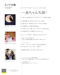
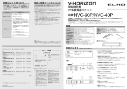
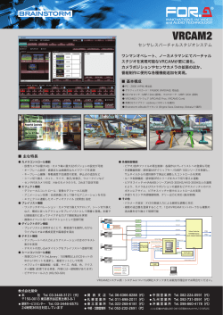
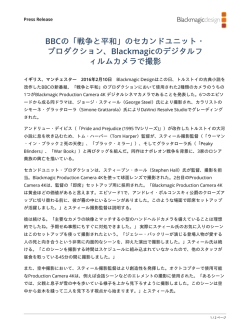
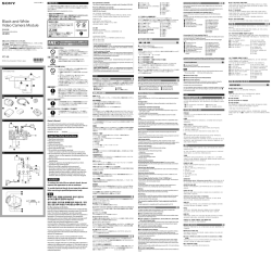
3-203-942-01 (1) 白黒ビデオカメラモジュール CCD Black-and-White Video Camera Module Owner’s Record The model and serial numbers are located on the bottom. Record the serial number in the space provided below. Refer to these numbers whenever you call upon your Sony dealer regarding this product. Model No. _____________ Serial No. ______________ This symbol is intended to alert the user to the presence of important operating and maintenance (servicing) instructions in the literature accompanying the appliance. お買い上げいただきありがとうございます。 電気製品は、安全のための注意事項を守らないと、けがをし たり周辺の物品に損害を与えることがあります。 この取扱説明書には、事故を防ぐための重要な注意事項と製品の取り扱い かたを示してあります。この取扱説明書をよくお読みのうえ、製品を安全 にお使いください。お読みになったあとは、いつでも見られるところに必 ず保管してください。 XC-ES50/ES50CE/ES30/ES30CE XC-EI50/EI50CE/EI30/EI30CE Sony Corporation 1999 Printed in Japan For the customers in the USA This equipment has been tested and found to comply with the limits for a Class A digital device, pursuant to Part 15 of the FCC Rules. These limits are designed to provide reasonable protection against harmful interference when the equipment is operated in a commercial environment. This equipment generates, uses, and can radiate radio frequency energy and, if not installed and used in accordance with the instruction manual, may cause harmful interference to radio communications. Operation of this equipment in a residential area is likely to cause harmful interference in which case the user will be required to correct the interference at his own expense. You are cautioned that any changes or modifications not expressly approved in this manual could void your authority to operate this equipment. The shielded interface cable recommended in this manual must be used with this equipment in order to comply with the limits for a digital device pursuant to Subpart B of Part 15 of FCC Rules. 安全のために ソニー製品は安全に充分に配慮して設計されています。しかし、まちがった 使いかたをすると、火災や感電などにより死亡や大けがなど人身事故につな がることがあり、危険です。 事故を防ぐために次のことを必ずお守りください。 Für Kunden in Deutschland Dieses Produkt kann im kommerziellen und in begrenztem Maße auch im industriellen Bereich eingesetzt werden. Dies ist eine Einrichtung, welche die Funk-Entstörung nach Klasse B besitzt. • 安全のための注意事項を守る。 • 長期間、安全にお使いいただくために、定期点検をすることをおすすめ します。点検の内容や費用については、お買い上げ店にご相談ください。 A • 故障したら使わずに、お買い上げ店にご連絡ください。 警告表示の意味 1 カメラ / Camera 行為を禁止する記号 カメラ設置の際は、周辺機器を含めてカメラに接続されている各機器間で接 地電位の差が生じないようにしてください。接地電位差により故障の原因と なる場合があります。設置の都合により電位差を生ずる場合は、機器の内い ずれかひとつの機器だけを接地するようにしてください。 2 GND2 うな表示をしています。表示の内容をよ 行為を指示する記号 内部の温度上昇を避けるため、動作中は布などで包まないでください。 使用・保管場所 Locations for operation and storage お手入れ レンズや光学フィルターの表面に付着したごみやほこりは、ブロアーで払っ てください。外装の汚れは、乾いた柔らかい布でふきとります。ひどい汚れ は、中性洗剤溶液を少し含ませた布でふきとった後、からぶきします。アル コール、ベンジンなどは、変質したり塗料がはげることがありますので、使 用しないでください。 概要 XC-ES/EIシリーズは固体撮像素子CCD(Charge Coupled Device)を採 用した白黒ビデオカメラモジュールです。 B 高画質 768×494画素のCCDにより、きめ細かな画像を再現します。 High image quality The interline transfer CCD provides a high-resolution image with 768 × 494 pixels (XC-ES50/ES30/EI50/EI30) or 752 × 582 pixels (XC-ES50CE/ ES30CE/EI50CE/EI30CE). 構成 を与えることがあります。 内部に水や異物を入れない 4 2 カメラケーブルCCXC-12P02N (2m)/05N (5m )/10N(10m)/ 25N(25m) カメラモジュール裏面のDC IN/SYNC端子に接続し、電力の供給や映像信 号の送出、同期信号の授受を行います。 5 3 Cマウントレンズ(可視光用) 推奨レンズ:VCL-08YM/12YM/16Y-M/25Y-M/50Y-M 分解しない、改造しない 分解や改造をすると、火災やけがの原因となります。 点検および修理は、お買い上げ店にご依頼ください。 4 カメラアダプターDC-700 AC電源から電力を供給する場合に、カメラモジュールに接続して使用しま す。映像信号の送出および同期信号の授受も行えます。 C 5 三脚アダプターVCT-333I 三脚を使ってカメラモジュールを固定するとき、このアダプターをカメラモ ジュールの底部に取り付けます。 XC-ES/EI カメラケーブルを傷つけない シリーズ 1 XC-ES/EI series 1 カメラケーブルを傷つけると、火災や故障の原因となる ことがあります。次の項目をお守りください。 • 設置時に、製品と壁やラック、棚などの間に、はさみ込 まない。 • カメラケーブルを加工したり、傷つけたりしない。 • 重いものをのせたり、引っ張ったりしない。 • 熱器具に近づけたり、加熱したりしない。 • カメラケーブルを抜くときは、必ずプラグを持って抜 く。 芯線の露出や断線などでカメラケーブルが傷んだら、お 買い上げ店に交換をご依頼ください。そのまま使用する と、火災の原因となります。 3 接続例 2 WEN HD 1 3 VIDEO 1 CAMERA AC IN 4 5 2 2 TRIG VD/SYNC 設置は確実に 1 2 3 4 5 6 モニター Cマウントレンズ(VCL-16Y-Mなど) 75Ω同軸ケーブル カメラケーブル(CCXC-12P05Nなど) TRIG発生器、画像処理装置 同期信号発生器 7 8 図C カメラモジュールを、カメラアダプターDC-700を介して電源に接続しま す。カメラアダプターDC-700の詳細については、DC-700の取扱説明書を ご覧ください。 6 5 9 1 2 3 4 5 6 7 8 9 DC IN/SYNC端子 VIDEO 1端子へ CAMERA端子へ ∼AC IN端子へ AC電源へ HD端子へ VD/SYNC端子へ HD出力 VD出力 各部の名称と働き 6 前面/上面/底面 1 2 この取扱説明書に記されている電源供給機器(カメラア ダプターなど)でお使いください。規定外の電源でのご 使用は、火災の原因となることがあります。 ご注意 Cマウント式のレンズとして、レンズマウント面からの飛び出し量が7mm以 下のものを使用してください。 1 レンズマウント部 2 7mm以下 2 カメラ固定用基準穴(上面) 3 カメラ固定用基準穴/三脚取り付け用ネジ穴(底面) カメラモジュール固定用に高い精度で切られたネジ穴です。ここでカメラモ ジュールを固定すると、光軸のずれを最小限にとどめることができます。 ◆ 寸法など詳しくは裏面右下の「ユーザーズガイドについて」をご覧ください。 指定されたカメラケーブル、接続ケーブルを使う この取扱説明書に記されているカメラケーブル、接続 ケーブルを使わないと、火災や故障の原因となることが あります。 3 2 External synchronization HD (horizontal drive), VD (vertical drive) signals: The camera module automatically determines whether to operate in interlace or noninterlace mode from the HD and VD signals input for external synchronization. Internal sync signal output You can output the HD and VD signals from the 12-pin connector by changing the rear panel switch. Electronic shutter function Shutter speed can be selected from a wide range (1/125 to 1/10000 sec.) or in flickerless (FL) mode. Body fixing The screw holes to install the camera module are located under the front panel (the CCD reference plane). Installing the camera module on the front panel minimizes deviation of the optical axis. The connector complies with the new EIAJ 12-pin assignment The new pin arrangement allows the connector to accept a trigger pulse and a WEN signal. System Components Fig. B 1 CCD Black-and-White Video Camera Module This is a small-size, high-resolution, monochrome video camera module using an interline transfer CCD image sensor. 2 CCXC-12P02N (2m, 6.6ft)/05N (5m, 16.4ft)/10N (10m, 32.8ft)/25N (25m, 82ft) camera cable This is attached to the DC IN/SYNC connector of the camera module and is used for power supply, transmission of video signals, and exchange of sync signals. 3 C-mount lens (For visible light) Recommended lens: VCL-08YM/12YM/16Y-M/25Y-M/50Y-M 4 DC-700/700CE camera adaptor This is connected to the camera module to enable power supply from ordinary AC power source, and also handles transmission of video signals from the camera module and exchange of sync signals between the camera module and an external sync signal generator. 5 VCT-333I tripod adaptor This attaches to the bottom of the camera module to fix the camera module to a tripod. 1 Connection example 底面の4つのカメラ固定用基準穴は三脚アダプター取り付け用ネジ穴としても 使用できます。三脚を使うときは、この4つのネジ穴を使って三脚アダプター VCT-333Iを取り付けます。 Fig. C Connecting DC-700/700CE (not supplied) Connect the camera module to the power via the camera adaptor DC-700/ 700CE. For details on the camera adaptor DC-700/700CE, see the DC-700/700CE Instruction Manual. 1 2 3 4 5 6 Monitor C-mount lens (e.g. VCL-16Y-M) 75-ohm coaxial cable Camera cable (e.g. CCXC-12P05N) TRIG generator, Image processor Sync signal generator 図D 1 レンズマウント(Cマウント) Cマウント式のレンズや光学機器を取り付けます。 D 指定された電源を使う Rear panel switches allow the following mode settings. • Gain: Auto/Manual • γ compensation • Synchronized input/output • Potential accumulation: FRAME/FIELD • 75Ω termination • Shutter speed: Normal/Trigger shutter DC-700(別売)との接続例 4 2 DC-700 Various mode settings The CCD Black-and-White Video Camera Module XC-ES/EI series system comprises the following optional products (available separately). 1 白黒ビデオカメラモジュール CCDを用いた、小型、高解像度の白黒カメラです。 水や異物が入ると、火災の原因となります。 万一、水や異物が入ったときは、すぐに本機が接続され ている電源供給機器の電源を切り、D C 電源ケーブルや 接続ケーブルを抜いて、お買い上げ店にご相談くださ い。 設置については、必ずお買い上げ店にご相談ください。 壁面や天井などへの設置は、本機と取り付け金具を含む 重量に充分耐えられる強度があることをお確かめくだ さい。充分な強度がないと、落下して、大けがの原因とな ります。 また、1年に1度は、取り付けがゆるんでいないことを点 検してください。 図B 白黒ビデオカメラモジュールXC-ES/EIシリーズを中心としたシステムの構 成品目は、次のとおりです。(いずれも別売りです。) 3 Overview リアパネルのスイッチの切り換えにより、以下のモード設定が可能です。 • ゲイン: 自動調整/手動調整 • γ補正 • 同期入出力 • 電荷蓄積: フレーム蓄積/フィールド蓄積 • 75Ω終端 • シャッタースピード: ノーマル/トリガーシャッター 新EIAJ12ピンコネクターピンアサイメント準拠 トリガーパルスやWEN信号を追加した、新しいピン配置になっています。 下記の注意事項を守らないと、 けがをしたり周辺の物品に損害 Use a blower to remove dust from the surface of the lens or optical filter. Clean the exterior with a soft, dry cloth. If the camera is very grimy, apply a cloth soaked in a mild detergent then wipe with a dry cloth. Do not apply organic solvents such as alcohol or benzine which may damage the finish. 多様なモード設定 筐体固定用のネジ穴がCCDの基準面が含まれているフロントパネルの下部に あります。ここでカメラモジュールを固定すれば、光軸のずれを最小限にと どめることができます。 2 Care The XC-ES/EI series is a monochrome video camera module using an interline transfer CCD (Charge Coupled Device) solid state image sensor. 筐体固定 1 Avoid operation or storage in the following places. • Extremely hot or cold locations. Recommended temperature range is 0°C to 40°C. (32°F to 104°F) • Humid or dusty locations • Locations exposed to rain • Locations subject to strong vibration • Near generators of strong electromagnetic radiation such as TV or radio transmitters. Before operating the unit, please read this manual thoroughly and retain for future reference. 電子シャッター F L (フリッカーレス)モードと豊富なシャッタースピード( 1 / 1 2 5 ∼ 1/10000秒)の中から、撮影条件に合った速度が選べます。 やその他の事故によりけがをしたり周 Heat radiation Do not wrap the camera in cloth or other material while in operation. There is a danger of overheating. 次のような場所での使用および保管はお避けください。 • 極端に暑い所や寒い所。適正使用温度は0∼40℃です。 • 湿気、ほこりの多い所。 • 雨にあたる所。 • 激しい振動のある所。 • 強力な電波を発生するテレビ、ラジオの送信所の近く。 GND3 辺の物品に損害を与えたりすることが The camera operates on +12V DC. Use a stable power source free from ripple or noise. Be careful not to spill liquids, or drop any flammable or metal objects in the camera body. コネクターから出力させることができます。 この表示の注意事項を守らないと、 火災 Power supply 放熱 内部同期信号出力 HD信号とVD信号は、リヤパネルのスイッチを変更することにより、12ピン 3 2 Abnormal electricity 4 Monitor Foreign bodies 3 4 When you install the camera with various peripheral devices and if the devices have different ground electric potential, ground only one device. In case there is an ground electric potential difference, the camera may be damaged. さい。 ンターレース方式かを自動的に識別し、その方式に応じて外部同期で動作 します。 く理解してから本文をお読みください。 Fig. A Notes on Operation 外部同期 HD、VD信号:入力されたHD、VD信号から、インターレース方式かノンイ GND1 When installing the camera 1 Power supply unit 3 Ground electric potencial difference 2 異常電流 4 モニター 電源について DC+12Vで動作します。リップル、ノイズのない安定した電源をお使いくだ この取扱説明書および製品では、 次のよ あります。 図A 使用上のご注意 To prevent fire or shock hazard, do not expose the unit to rain or moisture. Operating Instructions カメラ設置上のご注意 1 電源 3 接地電位差 WARNING 取扱説明書 English 日本語 1 2 3 4 5 6 7 8 9 DC IN/SYNC connector To VIDEO 1 connector To CAMERA connector To AC IN connector To AC power source To HD connector To VD/SYNC connector HD output VD output Location and Function of Parts and Operation Front/Top/Bottom Fig. D 1 Lens mount (C-mount) Attach any C-mount lens or other optical equipment. Note The lens must not project more than 7 mm (9/32 inch) from the lens mount. 1 Lens mount face 2 7 mm (9/32 inch) or less 2 Reference holes (Top) 3 Reference holes/Tripod screw holes (bottom) These precision screw holes are for locking the camera module. Locking the camera module into these holes secures the optical axis alignment. For details on dimensions, etc., see “About the User’s Guide” on the lower right of the back side. You can install the camera on a tripod. To install on a tripod, you will need to install a tripod adaptor VCT-333I to the camera on the reference holes of the bottom of the camera. E ピン番号 4 5 7 VD出力 (信号) 2 DC+12V 映像出力 (アース) 映像出力 (信号) HD出力 (アース) HD出力 (信号) 8 — 5 6 F 7 6 DIPスイッチの設定位置 / DIP switch setting a シャッタースピード Shutter speed 9 — 10 — 11 — 12 VD出力 (アース) (単位: 秒 / unit: second) シャッター 1 シャッタースピード設定(bit 1∼4) 撮影条件に応じたシャッタースピードに設定します。それぞれの設定 位置はイラストF-aを参照してください。工場出荷時のスイッチ設定 はシャッターOFFです。 2 電荷蓄積モード切り換え(bit 5) 切り換え位置はイラストF -bを参照してください。工場出荷時のス イッチ設定はFRAMEです。 3 リスタートリセット/外部トリガーシャッターモード切り換え(bit 6∼8) 各モードの設定位置はイラストF-cを参照してください。工場出荷時 のスイッチ設定はノーマルです。 4 γ補正ON/OFFスイッチ(bit 9) γ補正をするときONにします。設定位置はイラストF-dを参照して ください。工場出荷時のスイッチ設定はOFFです。 5 Gain(ゲイン)切り換えスイッチ(bit 0) このスイッチの切り換えにより、MGC(手動調整)、AGC(自動調 整)の各モードが選択できます。設定位置はイラストF-eを参照して ください。工場出荷時のスイッチ設定はMGC です。 ご注意 OFF Shutter OFF 1/125 1/250 1/500 1/1000 • リスタートリセット/外部トリガーシャッターモードのときは、F-cに 示した設定以外の組み合せでは使用しないでください。誤動作のおそれ があります。 • 外部トリガーシャッターモードに設定したときはbit 1∼4をすべて0の 位置にしてください。 6 手動ゲイン(M GAIN)調整つまみ DIPスイッチ5 – 5でMGC(手動調整)に設定した場合、このつまみでゲ インを調整できます。工場出荷時はMINに設定されています。 1/2000 1/4000 1/10000 フリッカーレス* 7 HD/VD信号入出力切り換えスイッチ カメラモジュールからHD/VD 信号を出力するときは INT 側に、外部から HD/VD信号を入力するときはEXT側に設定します。工場出荷時はEXT側に 設定されています。 Flickerless* (EIA: 1/100 CCIR: 1/120) 8 75Ω終端スイッチ 終端しないときはOFFにします。工場出荷時のスイッチ位置はONです。 三脚の取り付け 三脚アダプターVCT-333I(別売り)をカメラモジュールに取り付けてから 三脚に取り付けます。 三脚の取付部のネジは取付面からの飛び出し量(4)が下記のものを使用して ください。 4:4.5mm±0.2mm ISO規格 4 4:0.197インチ ASA規格 ご注意 * フリッカーレス設定時のbit 1∼3の位置は任意です。 Flickerless setting (bits 1- 3): Arbitrary 三脚アダプター(別売り)を取り付けるときは、三脚アダプターに付属のネ ジを使用してください。 b 電荷蓄積モード Potential accumulation mode フレーム フィールド 蓄積 蓄積 FRAME FIELD 画像系 撮像素子 有効画素数 光学黒期間 CCD垂直駆動周波数 CCD水平駆動周波数 信号方式 セルサイズ (水平/垂直) チップサイズ (水平/垂直) c リスタートリセット / 外部トリガーシャッターモード リスタート ノーマル* リセット Normal* Restart Reset モード2 モード1 * ノーマル設定時のbit 6, 7の位置は任意です。 Normal setting (bits 6 and 7): Arbitrary γ compensation γOFF XC-EI50: 0.1lx XC-EI30: 0.2lx IR cut Filterなし (ゲイン最大時、F1.4、γ補正ON) 60dB (TYP) e ゲイン切り換え Gain control γON MGC 映像S/N比 ゲイン 自動ゲイン調整/手動ゲイン調整 γ γ補正/γ=1 (リアパネルスイッチ) ホワイトクリップ 115IRE±10IRE 電荷蓄積モード フレーム/フィールド シャッター機能 ノーマルシャッター/外部トリガーシャッター シャッタースピード ノーマルシャッター:フリッカーレス 1/125、1/250、1/500、1/1000、1/2000、 1/4000、1/10000秒 (リアパネルスイッチにより切り 換え) 外部トリガーシャッター: 1/4∼1/10000秒 電源電圧 DC+12V (範囲:9∼16V) 消費電力 XC-ES50/EI50: 1.6W AGC 図E 後面 4 DC IN/HD/VD(DC電源/同期信号入出力)/VIDEO OUT端子(12ピ ンコネクター) カメラケーブルCCXC-12P05Nなどを接続して、DC+12Vの電力の供給を 受けるとともに、カメラモジュールからの映像信号を送出します。また、同 期信号発生器を接続して外部同期信号(HD/VD信号)を入力すれば、カメラ モジュールを外部同期で動作させることができます。この端子のピンNo.と 入出力信号その他の関係は次の表のようになっています。 (端子のピン配置はイラストE-4 を参照してください。) ピン番号 1 2 3 4 5 6 ピン番号 1 2 3 4 5 6 7 8 9 10 11 12 外部同期モード(HD/VD) ピン番号 アース DC+12V 映像出力 (アース) 映像出力 (信号) HD入力 (アース) HD入力 (信号) リスタートリセット アース 7 8 9 10 11 12 動作温度 保存温度 使用湿度 保存湿度 耐振動性 耐衝撃性 外形寸法 重量 付属品 XC-ES30/EI30: 1.4W −10∼+50℃ −20∼+60℃ 20∼80% (結露のない状態で) 20∼95% (結露のない状態で) 10G (20Hz∼200Hz) 70G 29 (W)×29 (H)×32 (D)mm 60g レンズマウントキャップ (1) 取扱説明書 (1) 仕様および外観は改良のため予告なく変更することがありますが、ご了承くださ い。 外部同期モード(HD/VD) VD入力 (信号) — — — — VD入力 (アース) 外部トリガーシャッター アース DC+12V DC+12V 映像出力 (アース) 映像出力 (アース) 映像出力 (信号) 映像出力 (信号) HD入力 (アース) HD入力 (信号) リセット (信号) — — — — リセット (アース) HD入力 (アース) HD入力 (信号) VD入力 (信号) — — WEN出力 (信号) トリガーパルス入力 (信号) VD入力 (アース) External Sync mode (HD/VD) Pin No. Pin No. External Sync mode (HD/VD) 1 Ground 7 VD input (Signal) 2 +12V DC 8 — 3 Video output (Ground) 9 — 4 Video output (Signal) 10 — 5 HD input (Ground) 11 — 6 HD input (Signal) 12 Pin No. VD input (Ground) Restart reset External trigger shutter Design and specifications are subject to change without notice. 1 Ground Ground 2 +12V DC +12V DC 3 Video output (Ground) Video output (Ground) 4 Video output (Signal) Video output (Signal) 5 HD input (Ground) HD input (Ground) 6 HD input (Signal) HD input (Signal) 7 Reset (Signal) VD input (Signal) 8 — 9 — 10 — WEN output (Signal) 11 — Trigger pulse input (Signal) 12 Reset (Ground) Pin No. Normal shutter: Flickerless 1/125, 1/250, 1/500, 1/1000, 1/2000, 1/4000, 1/10000 sec. (selected by switch on the rear panel) External trigger shutter XC-ES50/ES30/EI50/EI30: 1/4 to 1/10000 sec. XC-ES50CE/ES30CE/EI50CE/EI30CE: 1/4 to 1/8000 sec. Power +12V DC (Range: 9 to 16V) Power consumption XC-ES50/ES50CE/EI50/EI50CE:1.6W XC-ES30/ES30CE/EI30/EI30CE: 1.4W Operating temperature –10 to +50°C (14 to 122°F) Storage temperature –20 to +60°C (–4 to 140°F) Operating relative humidity 20 to 80% (no condensation) Storage relative humidity 20 to 95% (no condensation) Vibration resistance 10G (20Hz - 200Hz) Shock resistance 70G External dimension (w/h/d) 29 × 29 × 32 mm (1 3/16 × 1 3/16 × 1 5/16 inches) Mass 60g (2 oz) Accessories Lens mount cap (1) Operating Instructions (1) — — Camera sync output VD input (Ground) Pin No. Camera sync output 1 Ground 7 VD output (Signal) 2 +12V DC 8 — 3 Video output (Ground) 9 — 4 Video output (Signal) 10 — 5 HD output (Ground) 11 — 6 HD output (Signal) 12 VD output (Ground) 5 Shutter speed/Mode setting DIP switch See Fig. F 1 Shutter speed (bits 1–4) Set an appropriate shutter speed. See Figure F-a for the settings. (Factory setting: OFF) 2 Potential accumulation mode (bit 5) See Figure F-b for the settings. (Factory setting: FRAME) 3 Restart reset/External trigger shutter mode switch (bits 6–8) See Figure F-c for the settings. (Factory setting: Normal) 4 γ compensation ON/OFF switch (bit 9) Turn on this switch to enable the γ compensation. See Figure F-d for the setting. (Factory setting: OFF) 5 GAIN switch (bit 0) This switch selects MGC (manual adjustment) or AGC (automatic adjustment). See Figure F-e for the setting. (Factory setting: MGC) Note 6 Manual GAIN (M GAIN) control knob If you have set DIP switch 5-5 to MGC (manual adjustment), you can control the gain manually by adjusting this knob. (Factory setting: MIN) 7 HD/VD signal input/output switch Set the switch to INT to output the HD/VD signals from the camera module. Set the switch to EXT to input the HD/VD signals from an external unit. (Factory setting: EXT) 8 75Ω termination switch Turn off if you do not terminate. (Factory setting: ON) Using a tripod レンズマウント Cマウント フランジバック 17.526mm 同期方式 内部/外部(入力信号に応じて自動切り換え) 外部同期入出力 HD/VD (HD/VDレベル:2∼5Vp-p) 外部同期許容周波数偏差 ±1%(水平同期周波数に対して) ±50nsec以内 Hジッター 走査方式 525本 2:1インターレース/ノンインターレース (入力信号に応じて切り換え) 映像出力 1.0Vp-p、同期負、75Ω不平衡 水平解像度 570TV本 垂直有効ライン数 485本 (2:1インターレース時) 感度 XC-ES50: 400lx、F8 (γ=OFF、MIN Gain時) XC-ES30: 400lx、F11 XC-EI50: 400lx、F8 XC-EI30: 400lx、F5.6 最低被写体照度 XC-ES50/ES30: 0.3lx External Trigger External Trigger Shutter mode 2 Shutter mode 1 d γ補正 XC-ES50/EI50: インターライン転送方式1/2形CCD XC-ES30/EI30: インターライン転送方式1/3形CCD 768×494(水平/垂直) 各水平走査線のうち43画素 15.734kHz±1% 14.318MHz EIA XC-ES50/EI50: 8.4×9.8μm XC-ES30/EI30: 6.35×7.4μm XC-ES50/EI50: 7.95×6.45mm XC-ES30/EI30: 6.00×4.96mm 光学系、その他 Restart reset/External trigger shutter mode switch 外部トリガー シャッター 4 DC IN/HD/VD (DC power input/sync signal I/O)/VIDEO OUT connector (12-pin) You can connect a CCXC-12P05N camera cable to input the +12V DC power supply and to output the video signal from the camera module. When a sync signal generator is connected to this connector, the camera module is synchronized with the external sync signals. The pin configuration of this connector is as follows. (For details on the pin arrangement, see Figure E-4.) Shutter speed • Do not use any other settings for Restart reset/External trigger shutter mode except those shown in Figure F-c. Using other settings may cause the camera to malfunction. • If you set the External trigger shutter mode, set 0 in bits 1–4. 主な仕様 外部トリガー シャッター Fig. E Rear 5 シャッタースピード/各種モード設定用DIPスイッチ 図F参照 3 4 5 8 カメラ同期信号出力 アース 4 2 ピン番号 1 3 1 カメラ同期信号出力 ユーザーズガイドについて この取扱説明書は本機の基本的な機能と使用方法について記載しており ます。 より詳しい情報をお知りになりたい方は「ユーザーズガイド」をご覧くだ さい。 「ユーザーズガイド」については営業担当者にお問い合わせください。 お問い合わせ ソニー株式会社 コミュニケーションシステムソリューションネットワークカンパニー B&Pカンパニー イメージセンシングプロダクツ営業部 神奈川県厚木市岡田4-16-1 〒 243-0021 Tel. 046-227-2346 Fax. 046-227-2347 http://www.sony.co.jp/ISPJ/ ソニー株式会社 〒141-0001 東京都品川区北品川6-7-35 Printed in Japan To use the tripod, install the tripod adaptor VCT-333I (not supplied) on the camera module. Use a tripod screw with a protrusion (4) extending from the installation surface, as follows: 4 ISO standard: Length 4.5 mm ±0.2 mm ASA standard: Length 0.197 inches Note If you install a tripod adapter (not supplied), use the screws provided. Specifications Imaging system Pickup device XC-ES50/ES50CE/EI50/EI50CE: Interline transfer 1/2type CCD XC-ES30/ES30CE/EI30/EI30CE: Interline transfer 1/3type CCD Effective picture elements (horizontal/vertical) XC-ES50/ES30/EI50/EI30: 768×494 XC-ES50CE/ES30CE/EI50CE/EI30CE: 752×582 Optical blank 43 elements on each horizontal line CCD vertical drive frequency XC-ES50/ES30/EI50/EI30: 15.734kHz±1% XC-ES50CE/ES30CE/EI50CE/EI30CE: 15.625kHz±1% CCD horizontal drive frequency XC-ES50/ES30/EI50/EI30: 14.318 MHz XC-ES50CE/ES30CE/EI50CE/EI30CE: 14.1875 MHz Signal system XC-ES50/ES30/EI50/EI30: EIA system XC-ES50CE/ES30CE/EI50CE/EI30CE: CCIR system Cell size XC-ES50/ES50CE/EI50/EI50CE: 8.4×9.8 µm (horizontal/vertical) XC-ES30/ES30CE/EI30/EI30CE: 6.35×7.40 µm Chip size XC-ES50/ES50CE/EI50/EI50CE: 7.95×6.45 mm (horizontal/vertical) XC-ES30/ES30CE/EI30/EI30CE: 6.00×4.96 mm Optical system and others Lens mount Flange focal length Synchronization C- mount 17.526 mm Internal/external (automatically switched according to input signal) External sync signal I/O HD/VD (HD/VD level: 2-5 Vp-p) External sync allowable frequency ±1% (of horizontal sync frequency) H Jitter Within ±50 nsec Scanning system XC-ES50/ES30/EI50/EI30: 525 lines XC-ES50CE/ES30CE/EI50CE/EI30CE: 625 lines 2:1 interlace/noninterlace (automatically switched according to input signal) Video output 1.0 Vp-p, sync negative, 75 ohms unbalanced Horizontal resolution XC-ES50/ES30/EI50/EI30: 570 TV lines XC-ES50CE/ES30CE/EI50CE/EI30CE: 560 TV lines Vertical effective lines XC-ES50/ES30/EI50/EI30: 485 lines (with 2:1 interlace) XC-ES50CE/ES30CE/EI50CE/EI30CE: 575 lines Sensitivity XC-ES50: 400 lx, F8 (γ = OFF/Gain MIN) XC-ES50CE: 400 lx, F8 XC-ES30: 400 lx, F8 XC-ES30CE: 400 lx, F8 XC-EI50: 400 lx, F11 XC-EI50CE: 400 lx, F11 XC-EI30: 400 lx, F5.6 XC-EI30CE: 400 lx, F5.6 Minimum illumination XC-ES50/ES50CE/ES30/ES30CE: 0.3 lx XC-EI50/EI50CE: 0.1 lx XC-EI30/EI30CE: 0.2 lx No IR cut filter. (Maximum gain, F1.4, γ compensation ON) Video S/N ratio 60 dB (TYP) Gain AGC/Manual gain control γ γ compensation/γ=1 (selected by switch on the rear panel) White clip XC-ES50/ES30/EI50/EI30: 115 IRE±10 IRE XC-ES50CE/ES30CE/EI50CE/EI30CE: 805mV±70mV Charge accumulation Frame/Field Shutter Normal shutter/External trigger shutter About the User’s Guide The Operating Instructions describe the functions and use of this product. For more details, see the User’s Guide. Please ask your sales representative about the User’s Guide.
© Copyright 2026 Paperzz