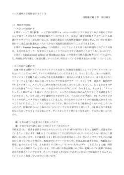
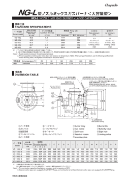
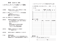
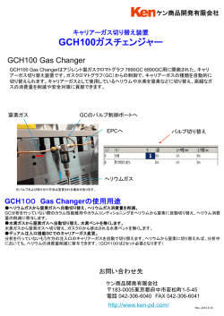
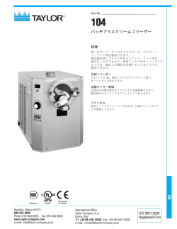
CB-237-01I
DGB 型ダブルコーンガスバーナ
DGB
DOUBLE-CONE GAS BURNER
安全性と省エネルギーを追求したオーブン用バーナ
Energy-conscious and safe burners for ovens
極めてターンダウン比が大きく、
その全範囲にわたり、
低空気比燃焼が行えるオーブン用省エネルギー型ガ
スバーナです。
燃焼制御機構をバーナに内蔵し、点火の極めて容
易な構造を採用しているため、乾燥・焼付設備など
の低温作業で優れた燃焼安定性を発揮します。
The DGB double-cone burner is capable of
combustion at a low excess air ratio throughout
a very wide turndown range.
Combustion stability in low temperature
applications such as in drying and baking
equipment is ensured because the combustion
control unit is built in and the structure of the
burner guarantees easy ignition.
特 長
FEATURES
1.
独特のダブルコーン方式
送風の流れの影響を受けないダブルコーン形状の燃焼室を採用。
保炎装置が要らず、
ダクトに直接取り付けることができます。
また燃焼室は、
レンガ、
キャスタブルなどの耐火断熱材を使用して
おらず、極めて清浄な熱風を発生します。
2.
省エネルギー
ターンダウン比20:1を実現するために、
ガスと空気の制御弁をバ
ーナに内蔵し、最高の燃焼性が維持できるように、
1次空気と2次
空気の比率を制御しています。このため全燃焼範囲にわたり、安
定した低空気比燃焼が行えます。乾燥炉や焼付炉などの作業変
化に幅広く対応し、燃費を大幅に低減します。
3.
ワンレバー操作
保守が極めて容易なワンレバー操作で、空気比を所定の値に保
ったまま、燃焼量を増減することができます。
4.
低NOx
2段燃焼方式の採用により、NOxを極めて低い値に抑えます。
5.
自動運転が可能
点火の極めて容易なパイロットバーナと火炎監視装置により、
自
動運転が行えます。
6.
燃料:都市ガス、天然ガス、
ブタンガス、プロパンガス
など
1. Unique double-cone design
The flame cone has a shape in which the flame is not
affected by air flow. No flame stabilizing unit is needed, and
the burner can be mounted directly in a duct.
Since the burner is all-metal using no refractory or
insulating material such as bricks and castable, clean hot
air is generated.
2. Fuel economy
With built-in gas and air flow regulators, a turn-down ratio of
20:1 is achieved. The ratio between the primary air and the
secondary air is controlled for optimum combustion to
ensure stable low excess air combustion over a full range of
firing rates. The burner is flexible for applications such as
dryers and baking ovens requiring a wide turndown range
and the fuel cost is greatly reduced.
3. One-lever operation
The burner is easy to use. The firing rate can be changed
by a single lever, while the excess air ratio is kept constant.
4. Low NOx
NOx emission is minimized because of the two-stage
combustion system.
5. Automatic operation
An easily ignited pilot burner, along with a flame detector,
enables automatic operation.
6. Various kinds of fuel can be used; town gas, natural
gas, butane gas, propane gas
1
標準構成
STANDARD COMPONENTS
空気
Air
①パイロットバーナ用ガスボールバルブ
②パイロットバーナ
③バーナ本体
④スパークプラグ
⑤ガスボールバルブ
⑥火炎監視装置(特別付属品)
③
⑥
②
パイロットガス
①
Pilot gas
ガス
Gas
④
⑤
このほかにバタフライバルブ、点火トランス、
キャブタイヤ
コードが付属します。
①Gas ball valve for pilot burner
②Pilot burner
③Burner body
④Spark plug
⑤Gas ball valve
⑥Flame detector (special accessory)
In addition to the above, a butterfly valve, an ignition
transformer and a cabtyre cord are supplied.
型番記号説明
DESIGNATION
DGB ー
60
Eー
記号
バーナサイズ
記号
Symbol
Burner size
Symbol
15
LP
30
60
80
100
標準6種類
LB
6 standard sizes
N1
N2
140
N3
6A
CG
LP
燃料種類
Type of fuel
プロパンガス
Propane gas
ブタンガス
燃料種類
Type of fuel
記号
Symbol
A1
ブタンエアーガス
Butane air gas
〃
A3
〃
41.8MJ/m3
A4
〃
46.0MJ/m3
〃
50.2MJ/m3
A6
〃
54.3MJ/m3
A7
〃
58.5MJ/m3
〃
62.7MJ/m3
A2
Natural gas
都市ガス 12A
Town gas 12A
A5
都市ガス 13A
Town gas 13A
都市ガス 6A
Town gas 6A
COG(クリーンなもの)
Coke oven gas
33.4MJ/m3(normal)
37.6MJ/m3
Butane gas
天然ガス
33.4MJ/m3
A8
37.6MJ/m3(normal)
41.8MJ/m3(normal)
46.0MJ/m3(normal)
50.2MJ/m3(normal)
54.4MJ/m3(normal)
58.6MJ/m3(normal)
62.8MJ/m3(normal)
注)1.
ブタンエアガスをご使用のときは、発熱量と組成(または密度)
をご連絡ください。
2.
製鉄所COGは必ずクリーンな脱硫ガスをご使用ください。
3.
ブタンエアーガスは、標準状態の発熱量を示します。
Note)1. When butane air gas is used, inform us of the calorific value and composition(or density).
2. If coke oven gas is used, it should be free from tar and desulfurized.
3. Butane air gas shows the calorific value of a standard state.
2
構造説明
CONSTRUCTION
燃焼空気はエアーコントロールバルブで流量調節された後スピン
エアーノズルと2次空気ノズルに供給され、
フレームコーン内に入
ります。
ガスノズルは空気と完全に混合させるために独特の構造となって
おり、
ノズルより噴出したガスはスピンエアーノズルで強力な旋回
を与えられた空気と急速に混合し、
さらに2次空気ノズルからの空
気と混合して燃焼します。
アシストエアーは燃焼負荷に応じて最適量にコントロールされ、低
負荷燃焼時にはガスと空気の混合速度を促進します。
ガスコントロールレバーとエアーコントロールレバーはリンケージで
連結しており、
ワンレバー操作でガス量と空気量を同時に比例調
節します。
したがって高負荷燃焼から低負荷燃焼まで広い燃焼範
囲にわたり、低空気比で安定した燃焼ができます。
空気
Air
③
④
①
⑤
②
⑥
ガス
⑨
Gas
⑦
The air control valve controls the combustion air flow. The
combustion air is then supplied into the spin air and
secondary air nozzles and enters the flame cone.
The gas nozzle has a unique design to mix gas and air
completely. The gas jets from the nozzle and is rapidly
mixed with the air powerfully swirled by the spin air nozzle.
It is further mixed with the air from the secondary air nozzle
and is completely burned.The assisting air is controlled for
the optimal flow according to the firing rate, and promotes
the gas and air mixing speed at a low firing rate. The gas
control lever and air control lever are linked together, and
one-lever operation performs the proportional control of the
gas flow and the air flow at the same time. This ensures
stable, low excess air ccombustion over a full range of firing
rates.
パイロットガス
Pilot gas
⑧
① エアーコントロールレバー
② アシストエアー入口
③ エアーコントロールバルブ
④ 火炎監視装置
⑤ フレームコーン
⑥ ガスコントロールレバー
⑦ スピンエアーノズル
⑧ パイロットバーナ
⑨ 2次空気ノズル
取付寸法
空気
B
INSTALLATION
① Air control lever
② Assisting air inlet
③ Air control valve
④ Flame detector
⑤ Flame cone
⑥ Gas control lever
⑦ Spin air nozzle
⑧ Pilot burner
⑨ Secondary air nozzle
A
Air
C
D
φL
φK
φJ
φH
1
2
3
4
φG
7 8 9
5 6
10
F
E
取付ボトル孔
M個-φN
ガス
Gas
Mounting bolt hole
No. of holes: M
Dia. of a hole: φN
パイロットガス
Pilot gas
バーナ型番
A
B
C
D
E
F
φG
φH
φJ
φK
φL
M個
φN
Burner model
接管径
Pipe connection
空気
Air
DGBー 15E
DGBー 30E
DGBー 60E
DGBー 80E
DGBー100E
DGBー140E
565
565
706
706
811
811
104
116
132
132
188
188
232
220
285
285
305
305
150
150
185
185
185
185
12
12
12
12
16
16
300
300
360
360
430
430
241.8
241.8
318.5
338
410
466
310
310
380
380
510
510
350
350
430
430
560
560
430
430
510
510
685
685
480
480
560
560
740
740
8
8
12
12
12
12
19
19
19
19
22
22
80A
100A
125A
125A
150A
150A
質量
kg
ガス パイロットガス Weight
Fuel gas Pilot gas
RC3/4B
RC 1 B
RC11/2B
RC11/2B
RC 2 B
RC 2 B
10A
10A
10A
10A
10A
10A
kg
54
57
80
83
135
140
3
DGB 型ダブルコーンガスバーナ
DGB
DOUBLE-CONE GAS BURNER
バーナ特性
火炎形状
Flame dimensions
812
600
696
500
400
300
燃焼量(kW)
700
燃焼空気量
Combustion
air flow
580
L
464
バーナ型番
348
200
232
100
116
0
1
0
φD
1.6
1.4
1.2
1.0
928
燃焼量
Firing rate
2
●燃焼条件
バ ー ナ:DGB-60E
燃 料:ブタンエアガス
3
]
[50.2MJ/m(normal)
ガス圧力:6 kPa
空気圧力:6 kPa
空気温度:40℃
3
4 5 6 7 8
バーナ開度目盛
Burner opening scale
9 10
●Firing conditions
Burner model:DGB-60E
Fuel:Butane air gas
3
]
[50.2MJ/m(normal)
Gas pressure:6 kPa
Air pressure:6 kPa
Air temperature:40℃
DGBー 15E
DGBー 30E
DGBー 60E
DGBー 80E
DGBー100E
DGBー140E
1.DGB 型バーナは熱風循環フ
ァンの吸込側、吐出側のどちら
にも取り付けられます。
閉
150
2.DGB 型バーナで加熱される熱
風の最高温度は400℃です。
Recirculated or
low temperature air
●ダクト寸法
●Minimum duct dimensions
□A
L
DGBー
15E
□A(mm) 500
L (mm) 1600
30E
500
1600
60E
600
1800
80E
600
2000
100E
700
2000
140E
750
2300
Power for operating the
burner lever is in the table
below : Take care that the
linkage is not subject to
unreasonable force. Take
care that the burner lever
works smoothly by avoiding
excessive heat.
1
循環または
低温空気
R
High temperature air
Control motor
Model: MC-1
バーナレバー操作に要する動力
は下表の通りです。実際にはリ
ンケージに無理な力がかかった
り、温度その他でバーナレバー
の動きが悪くならないように注
意してください。
R
高温空気
1. The burner can be mounted
either on the suction or
delivery side of a
recirculating fan.
2. The burner is applicable to
the maximum hot air
temperature of 400℃.
3. The air velocity at the
burner mounting area
inside the duct should be 5
meters per second.
4. The minimum duct
dimensions are as follows:
コントロール
モータ
型式:MC-1
6 7 8 91
0
45
●Mounting on the recirculating fan delivery side
開
4.
ダクト寸法は下記寸法より大き
くとってください。
3
●循環ファン吐出側に取り付けた場合
3.
バーナ取り付け部におけるダクト
内流速は5m/sにしてください。
2
Recirculated or
low temperature air
空気入口
Air inlet
1
高温空気
●Firing conditions
Burner load:100%
Duct atmosphere:
O2 concentration 15% or higher
15%以上
LINKAGE
High temperature air
300
350
400
450
500
550
ダクト内雰囲気:O2濃度
MOUNTING IN DUCT
循環または
低温空気
800
1000
1300
1500
1600
1800
燃 焼 負 荷 率:100%
リンケージ
●Mounting on the recirculating fan suction side
φD
●燃焼条件
ダクトへの取付
●循環ファン吸込側に取り付けた場合
L
Burner model
2
800
空気比
Excess air ratio
流量・空気比特性
Flow and excess air ratio characteristics
Firing rate(kW)
燃焼空気量[m3/h(normal)]
Combstion air flow[m3/hr(normal)]
BURNER CHARACTERISTICS
バーナ型番
Burner model
DGBー 15E
DGBー 30E
DGBー 60E、 80E
DGBー100E、140E
アーム長さ
(mm) パワーF
パワーF
Arm length(mm) Power F
Torque
R1
R2
(N)
130
130
130
180
150
150
150
205
9.8
9.8
11.8
14.7
R2×F
(N・m)
1.5
1.5
1.8
3.5
4
DGB 型ダブルコーンガスバーナ
DGB
DOUBLE-CONE GAS BURNER
標準仕様
STANDARD SPECIFICATIONS
バーナ型番
空気圧力 5kPa
空気圧力 6kPa
空気圧力 7kPa
Air pressure 5kPa
Air pressure 6kPa
Air pressure 7kPa
最大空気量
m3/min※
Burner model
DGBー 15E
DGBー 30E
DGBー 60E
DGBー 80E
DGBー100E
DGBー140E
燃焼量 kW
Firimg rate kW
Max. air flow
[m3/min(normal)]
Maximum
2.7
5.5
10.9
14.5
18.7
26.2
159
316
633
844
1055
1482
最 大
最大空気量
m3/min※
最 小
Max. air flow
8
16
31
42
53
74
3.0
6.0
12.0
16.0
20.5
28.7
燃焼量 kW
最 大
3
Minimum [m /min(normal)] Maximum
注)
1.
ガス供給圧力は空気圧力と同圧で供給してください。
(バーナ入口部圧力)
2.
燃焼量は燃料がブタンエアガス[50.2MJ/m3(normal)]で空気温度が40℃の場合を示します。
燃料が異なる場合は、前記の型番記号説明の燃料記号を参照し、右記係数で燃焼量を補正し
てください。
3.
※の項目は、標準状態の流量を示します。
174
348
698
930
1163
1628
燃料記号
Symbol of fuel
係 数
Coefficient
Note) 1. Supply the fuel gas at the same pressure at the burner inlet as that of the air.
2. The above table shows firing rates when using air-diluted LPG[
50.2MJ/m3(normal)]and 40℃. air. If other kind of fuel is used, refer to the symbol
of fuel indicated in DESIGNATION above and the coefficient for each symbol to
calculate the firing rate.
3. ※ item shows the flux of a standard state.
燃焼量 kW
最大空気量
m3/min※
Firimg rate kW
最 小
Max. air flow
9
17
35
46
58
81
3.2
6.5
13.0
17.3
22.1
31.0
Firimg rate kW
最 大
最 小
3
Minimum [m /min(normal)] Maximum
LP,LB
9
18
37
50
63
88
188
375
751
1002
1252
1754
N1∼N3 A1∼A8
0.96
Minimum
0.94
1.0
CG
6A
1.06
1.17
標準付属品
STANDARD ACCESSORIES
バタフライ
バルブ
Butterfly
valve
バーナ型番
Burner model
DGBー 15E DGBー 30E DGBー 60E,80E
DGBー100E DGBー140E FBVー 80
FBVー100
FBVー125
FBVー150
FBVー150
ガスボールバルブ
パイロット
バーナ
Gas ball valve
LP,LB
N1ーN3
A1ーA8
6A
CG
GBCー20
GBCー25
GBCー40
GBCー50
GBCー65
GBCー25
GBCー40
GBCー50
GBCー65
GBCー65
32A
40A
50A
65A
65A
注)
1.
LP、LBなどは前記の型番記号説明の燃料記号を示します。
2.
パイロットバーナはメインバーナの本体に組み込まれています。
3.
パイロットバーナ用ガスボールバルブの( )内は燃料記号がCGの場合を示します。
Pilot
burner
パイロットバーナ用
ガスボールバルブ
Gas ball
valve
for pilot
burner
スパーク
プラグ
点火
トランス
キャブ
タイヤコード
Spark
plug
Ignition
transformer
Cabtyre
cord
強化シリコンゴム
絶縁電線 2m
NPCー10
GBCー10
(UBー10)
Cー6HA
パイロットバーナ
SPECIAL ACCESSORIES
PILOT BURNER
Burner model
15E
ガス減圧弁
Gas reducing
valve
1次圧力:
30E
Primary
pressure
DGB ー 60E
10∼20kPa
80E
100E
140E
2次圧力:
Secondary
pressure
3∼8kPa
ガス微圧計
Gas micropressure gauge
火炎監視装置
Flame detector
フレームセンサー
φ75×10kPa
および
(ゲージコック付き) フレームリレー
φ75×10kPa
with gauge
cock
Flame sensor
and
flame relay
silicone rubber
2 meters
Note) 1. 'LP', 'LB', etc. indicate symbols of fuel shown in DESIGNATION above.
2. The pilot burner is incorporated into the main burner.
3. 'UB-10' in the above table is for the symbol of fuel 'CG'.
特別付属品
バーナ型番
GS10 O23 Cable insulated
with reinforced
ーZC
DGB 型バーナのパイロットバ
ーナにはNPC-10型ノズルミッ
クス式を採用しています。
Model
The burner uses model
NPC-10 pilot burner.
燃料
型番
NPC-10
LPG
天然ガス
Fuel
Natural gas
都市ガス
Town gas
ブタンエアーガス
Butane air gas
燃焼量
Firing rate
ガス圧力
Gas pressure
11.6kW
6kPa
5
DGB 型ダブルコーンガスバーナ
DGB
DOUBLE-CONE GAS BURNER
システムフロー
SYSTEM FLOW
点火準備完了
パイロットバーナ点火
点火タイマー メインバーナ
タイムアップ
点火
消火
(または異常失火) (警報停止)
Ignition preparations
Ignition timer Main burner
completed Pilot burner ignites counts down
lights
Flame shutoff
(or flame failure)
Alarm off
停止
Stop
プリパージ
Prepurge
点火トランス
Ignition transformer
パイロットガス電磁弁
Pilot gas solenoid valve
火炎監視装置
Flame detector
メインガス電磁弁
Main gas solenoid valve
警報ブザー
異常失火時のみ
Alarm buzzer
In the event of flame failure
注)パイロットバーナはメインバーナ点火後消火しますが、
メインバーナの火炎は同一の火炎監視装置で監視を行います。そのため、時限パイロット方式でご使用ください。
Note) The pilot bunner is put out after the main burnner is fired up. The main flame is observed by the same flame detector. Please use the burner in interrupted pilot mode.
配管系統図
PIPING DIAGRAM
熱電対
Thermocouple
大気へ
To outside
コントロールモータ
Control motor
火炎監視装置
Flame detector
高圧設定
High pressure setting
低圧設定
Low pressure setting
圧力スイッチ
Pressure switch
メイン遮断弁
Main shutoff valve
メイン遮断弁
Main shutoff valve
DGB 型バーナ
DGB burner
燃料ガス
Fuel gas
パイロットバーナ
Pilot burner
遮断弁
Shutoff valve
減圧弁
Reducing valve
パイロット遮断弁
Pilot gas shutoff valve
点火トランス
Ignition transformer
※ 本カタログはSI単位を採用しています。従来単位とは下記数式にて換算してください。
*This catalog uses the SI units which can be calculated from the following formula:
●1kcal/h=1.163×10-3kW 1kW=860kcal/h ●1kcal=4.18kJ(10000kcal=41.8MJ) 1kJ=0.239kcal(1MJ=239kcal) ●1mmH2O=1kg/m2=9.81Pa(1kg/㎝2=98.1kPa) 1Pa=0.102mmH2O(1kPa=102mmH2O)
安全に関するご注意:ご使用の際は、取扱説明書をよくお読みの上、正しくお使いください。
SAFETY PRECAUTIONS : Read the instruction manual carefully before using the equipment.
URL http://www.chugai.co.jp
堺 事 業 所 〒592-8331 堺市西区築港新町2丁4番
(072)247-1440
(直通) FAX(072)247-1441
サーモシステム事業部 TEL
Sakai Works : 2-4,Chikko-Shinmachi,Nishi-ku,Sakai 592-8331,Japan
Tel +81-72-247-1440 Fax +81-72-247-1441
東 京 支 社 〒108-0075 東京都港区港南2丁目5番7号(港南ビル)
サーモシステム事業部 TEL(03)5783-3378(直通) FAX(03)5783-3368
Tokyo Branch : 2-5-7,Konan,Minato-ku,Tokyo 108-0075,Japan
Tel +81-3-5783-3378 Fax +81-3-5783-3368
名古屋営業所 〒450-0003 名古屋市中村区名駅南1丁目21番19号(本州名駅ビル)
TEL(052)561-3561(代表) FAX(052)561-3566
Nagoya Sales Office: 1-21-19,Meieki-Minami,Nakamura-ku,Nagoya 450-0003,Japan
Tel +81-52-561-3561 Fax +81-52-561-3566
燃 焼 研 究 所 〒582-0027 大阪府柏原市円明町1000番地6
TEL(072)977-8503(代表) FAX(072)978-6981
Combustion Laboratory: 1000-6,Enmyo-cho,Kashiwara,Osaka 582-0027,Japan
Tel +81-72-977-8503 Fax +81-72-978-6981
●記載内容について、改良のため予告なしに変更する場合もありますので、あらかじめご了承ください。
●The descriptions and specifications are subject to change without notice.
6
130900(M)Printed in Japan
© Copyright 2026 Paperzz