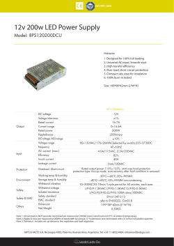
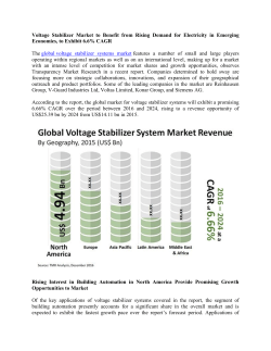
040-03-402-009-EH-1215.pdf 040-03-402-009-EH-1215 07df031a022110011000883832007442 600-650 WATT MEDICAL POWER SUPPLIES DESCRIPTION The PM651 series of AC-DC switching power supplies in a PM651 SERIES package of 4 x 8 x 2.58 inches are capable of delivering RoHS 600-650 watts of continuous power at 30 CFM forced air cooling. The units are constructed on a printed circuit board with a U-bracket for mechanical support and heat sinking. A cover and fan assembly can be added during manufacturing. They are designed for medical applications including those needing BF rated insulation and/or an operation altitude up to 5000 meters. FEATURES SAFETY STANDARD APPROVALS BF Class insulation Operation up to 5000 meters 1 0 0 - 2 4 0 VA C i n p u t w i t h a c t i v e P F C , 0 . 9 8 t y p i c a l Less than 300 μA leakage current St a n d b y o u t p u t 5 V D C a t 2 0 0 m A E N 5 5 0 11 C l a s s B c o n d u c t e d e m i s s i o n s Inhibit - TTL high to disable output Compliant with RoHS requirements INPUT SPECIFICATIONS Input voltage: Input frequency: Input current: Earth leakage current: 90-264 VAC 47-63 Hz 8.4 A (rms) @115 VAC, 60 Hz 4.2 A (rms) @ 230 VAC, 50 Hz 300 μA max. @ 264 VAC, 63 Hz GENERAL SPECIFICATIONS OUTPUT SPECIFICATIONS Output voltage/current: Maximum output power: Ripple and noise: Remote sense Overvoltage protection: Protected to output short circuit conditions Thermal shutdown Protected to over temperature conditions Temperature coefficient: Transient response: Standby power All outputs ±0.04% /℃ maximum Maximum excursion of 4%, recovering to 1% of final value within 500 us after a 25% step load change 5 V at 200 mA maximum Fan power 12 V at 500 mA maximum Typical 88% Hold-up time: 12 ms minimum at 110 VAC & 650 W Line regulation: ±0.5% maximum at full load Inrush current: 20 A @ 115 VAC, or 40 A @ 230 VAC, at Withstand voltage: 4000 VAC from input to output (2 MOPP) 1500 VAC from input to ground (1 MOPP) 1500 VAC from output to ground MTBF: 250,000 hours at full load at 25℃ ambient, calculated per MIL-HDBK-217F EMC Performance EN55011 ENVIRONMENTAL SPECIFICATIONS Operating temperature: Storage temperature: Relative humidity: Derating: 85 KHz (typical) Efficiency: 25℃ cold start See rating chart. See rating chart. 1% peak to peak maximum Compensation for cable losses up to 0.5V Set at 115-140% of nominal output voltage Overcurrent protection: Switching frequency: -10℃ to +70℃ -40℃ to +85℃ 5% to 95% non-condensing Derate from 100% at +50℃ linearly to 50% at +70℃, applicable to convection and forced-air cooling conditions Class B conducted, class A radiated FCC: Class B conducted, class A radiated VCCI: Class B conducted, class A radiated EN61000-3-2: Harmonic distortion, class A and D EN61000-3-3: Line flicker EN61000-4-2: ESD, ±8 KV air and ±6 KV contact EN61000-4-3: Radiated immunity, 3 V/m EN61000-4-4: Fast transient/burst, ±2 KV EN61000-4-5: Surge, ±1 KV diff., ±2 KV com EN61000-4-6: Conducted immunity, 3 Vrms EN61000-4-8: Magnetic field immunity, 3 A/m EN61000-4-11: Voltage dip immunity, 30% reduction for 500 ms, 60% reduction for 100 ms and >95% reduction for 10 ms 41 040-03-402-009-EH-1215.pdf 040-03-402-009-EH-1215 07df031a022110011000883832007442 UNIVERSAL INPUT PM651 MEDICAL SERIES INTERFACE SIGNALS OUTPUT POWER DERATING CURVE PFD: TTL high for normal operation, low upon loss of input power, turn-on delay time 100-750 ms, turn-off delay time 1 ms minimum Inhibit: TTL high to turn off output OUTPUT VOLTAGE/CURRENT RATING CHART (1) Min. (2) Current 0.1 A 0.1 A 0.1 A 0.1 A 0.1 A 0.1 A 0.1 A 0.1 A Output Max. Current (3) at 30 CFM 50.00 A 40.00 A 36.12 A 27.09 A 23.22 A 18.06 A 13.55 A 11.41 A Ripple & (4) Noise 120 mV 150 mV 180 mV 240 mV 280 mV 360 mV 480 mV 570 mV Max. Output (3) Power 600 W 600 W 650 W 650 W 650 W 650 W 650 W 650 W Efficiency (typical) @600-650W 115/230 Vac 87 /89% 87 /89% 87 /89% 86 /88% 86 /88% 86 /88% 88 /89% 88 /89% Model V1 Tol. PM651-12B 12 V ±2% PM651-13B 15 V ±2% PM651-13-1B 18 V ±2% PM651-14B 24 V ±2% PM651-15B 28 V ±2% PM651-17B 36 V ±2% PM651-18B 48 V ±2% PM651-19B 57 V ±2% NOTES: 1. Change suffix “B” for U-Bracket form to “C” for enclosed form with cover and fan assembly, e.g. PM651-14C. 2. All models may be operated at no-load without damage. At no load, output voltage fluctuates beyond 5% due to the burst-mode operation of the control IC in them for energy saving. 3. 600-650 W for “C” version, or with 30 CFM forced air provided by user for “B” version 4. Ripple and noise is maximum peak-to-peak voltage value measured at output within 20 MHz bandwidth, at rated line voltage and output load ranges, and with a 10 μF tantalum capacitor in parallel with a 0.1 μF ceramic capacitor across the output. MECHANICAL SPECIFICATIONS U-bracket Form Enclosed Form NOTES: 1. Dimensions shown in inches [mm] 2. Tolerance 0.02 [0.5] maximum 3. Input connector P1 is Dinkle terminal P/N DT-35-B01W-03, with nickel plated M3 screws. 4. Output connector P2 is Dinkle terminal P/N DT-4N-B01W-06, with nickel plated M3.5 screws. 5. Output connector P3 is JST header B10B-PHDSS or equivalent, mating with JST housing PHDR-10VS or equivalent. 6. Fan connector P4 is JST header S2B-ZR-3.4 or equivalent, mating with JST housing ZHR-2 or equivalent. 7. Weight: 1.8 Kgs (3.97 lbs.) approx. for U-bracket form, 2.0 Kgs. (4.41 lbs.) approx. for enclosed form. 8. Maximum penetration of fixing screws is 4 mm from the outer surface of chassis. 42 040-03-402-009-EH-1215.pdf 040-03-402-009-EH-1215 07df031a022110011000883832007442 UNIVERSAL INPUT PM651 MEDICAL SERIES PIN CHART Connector P1 (AC) P2 PIN NO 1 2 3 Polarity Ground Live Neutral 1 2 3 P4 4 5 6 Common Return +V1 Connector 1 2 +12V Fan Common Return P3 PIN NO 1 2 3 4 5 6 7 8 9 10 Polarity +V1 Sense -V1 Sense PFD Common Return N.A. N.A. Inhibit N.A. +5V Standby +5V Standby Return 43 Headquarter Switzerland: Pewatron AG Thurgauerstrasse 66 CH-8052 Zurich Phone +41 44 877 35 00 [email protected] Office Germany: Pewatron AG Neumarkter Straße 86a D-81673 Munich Phone +49 89 260 38 47 [email protected] We are here for you. Addresses and Contacts. Sales Switzerland & Liechtenstein Sales International Key Accounts Postcode 3000 – 9999 Postcode 1000 – 2999 Basil Frei Pewatron AG Thurgauerstrasse 66 CH-8052 Zurich Eric Letsch Pewatron AG Thurgauerstrasse 66 CH-8052 Zurich Peter Felder Pewatron AG Thurgauerstrasse 66 CH-8052 Zurich Phone + 41 44 877 35 18 Mobile + 41 76 279 37 26 Phone + 41 44 877 35 14 Mobile + 41 76 491 66 70 Phone + 41 44 877 35 05 Mobile + 41 79 406 49 83 [email protected] [email protected] [email protected] Sales Germany Postcode 00000 – 31999 Postcode 38000 – 39999 Postcode 80000 – 99999 Postcode 32000 – 37999 Postcode 40000 – 79999 Sales Austria Kurt Stritzelberger Pewatron AG Neumarkter Straße 86a D-81673 Munich Gerhard Vetter Pewatron AG Fürstenbergstraße 12 D-55422 Bacharach-Medenscheid Kurt Stritzelberger Pewatron AG Neumarkter Straße 86a D-81673 Munich Phone + 49 89 260 52 80 Mobile + 49 171 803 41 35 Phone + 49 674 394 75 75 Mobile + 49 163 762 74 30 Phone + 49 89 260 52 80 Mobile + 49 171 803 41 35 [email protected] [email protected] [email protected] Pressure Sensors Gas sensors / Gas sensor modules Load cells Linear position sensors Angle sensors Philipp Kistler Phone + 41 44 877 35 03 [email protected] Thomas Clausen Phone + 41 44 877 35 13 [email protected] Eric Letsch Phone + 41 44 877 35 14 [email protected] Accelerometers Power supplies Current sensors Eric Letsch Phone + 41 44 877 35 14 [email protected] Sebastiano Leggio Phone + 41 44 877 35 06 [email protected] Sebastiano Leggio Phone + 41 44 877 35 06 [email protected] Drive technology CH Postcode 5000 – 9999 / DE Drive technology CH Postcode 1000 – 4999 / AT / IT / FR Roman Homa Mobile + 41 79 444 00 86 [email protected] Christian Mohrenstecher Mobile +41 76 444 57 93 [email protected] Sales Other Countries / Product Management Competitive sensor & power supply solutions worldwide
© Copyright 2026 Paperzz