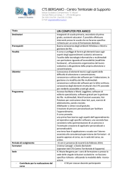
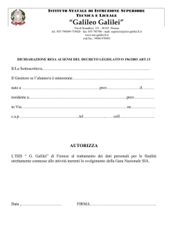
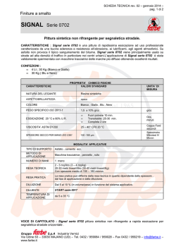
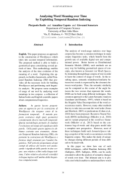
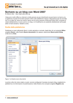
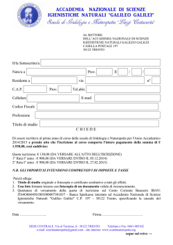
Contact!
First Acquisition and Tracking of Galileo IOV Signals
Europe’s GNSS program — Galileo — entered a new phase
of development with the recent launch of two in-orbit
validation satellites, which comprise the first elements
of the system’s fully operational constellation. In this
article, a team of Italian researchers present the initial
results of their analysis of the Galileo signals.
O
Navigation, Signal Analysis and
Simulation (NavSAS) Group
Politecnico di Torino/Istituto
Superiore Mario Boella
46
InsideGNSS n December 12, 2011, one of
the two Galileo in-orbit validation (IOV) satellites launched
on October 21 — the GalileoProtoFlight Model (PFM) spacecraft —
started transmitting its payload signal
on the E1 band over Europe.
That same day NavSAS researchers
were able to acquire and track the E1
signal (Galileo Code Number 11) beginj a nu a ry/ febru a ry 2012
ning at 14:46:15 CET. Two days later,
on December 14, the E5 signal became
available as well.
The E1 signal was received on
December 12 at the Istituto Superiore
Mario Boella (ISMB) premises (located
in Torino, Italy) with a non-directive
antenna, a commercial narrowband RF
front-end, and a proprietary software
receiver, developed by our research
group. The team first received the PFM
E5 signal on December 14, using a similar experimental setup.
In this article we will discuss the
first acquisition and tracking of the
signal broadcast by the Galileo-PFM
satellite, on both E1 and E5 bands. We
will describe the receiving equipment
configuration and present our initial
www.insidegnss.com
The Galileo In-Orbit Validation (IOV)
ProtoFlight Model (PFM) and Flight
Models (FM-2, FM-3 and FM-4)
undergoing assembly and testing
at Thales Alenia Space’s facility in
Rome.
Photo credit: ESA - S. Corvaja, 2011
results on signal acquisition, tracking, data demodulation and joint PVT
(position, velocity, time) solution as a
first receiver-side validation of the new
Galileo system.
Experimental Setup for
Galileo IOV Acquisition
The radio frequency (RF) signal was
received by means of two fixed, nondirectional rooftop antennas, co-located
at ISMB premises in Torino at the following coordinates: latitude = 45°03’54.99”
N, longitude = 7°39’32.29” E, height =
311.97 meters.
The Galileo-PFM IOV navigation
payload began by transmitting the E1
signal; so, our first acquisition and tracking test focused on this signal.
www.insidegnss.com Using a commercial GPS/Galileo
receiver front-end, the RF signal was
filtered, amplified, and downconverted
to intermediate frequency (IF) while
also being converted to a digital format.
The front-end features a bandwidth of
approximately four megahertz and samples the signal at 16.3676 MHz, using
one bit per sample.
The digital IF samples were transferred via a USB interface to a PC, where
they could be either stored in memory
or processed in real-time with the
N-GENE receiver, a prototype fully software receiver developed by our group
and used in our research activities.
Postprocessing of the stored data collections was done both with N-GENE
and with ad hoc routines developed
using a commercial high-level technical computing language and interactive
environment.
Because the day and time of the
IOVs’ navigation signal switch-on were
unknown, we ran an automatic procedure that searched all Galileo code numbers every 10 minutes. At each search,
the N-GENE software receiver calculated the cross-ambiguity function (CAF)
of the received signal with local codes
and a variable Doppler shift within ±7
kilohertz. When the receiver recognized
a valid acquisition peak in the CAF, it
displayed an alert message on the PC’s
screen and a two-minute data collection of raw samples — accurately timestamped — was stored on disk.
We checked the system in lab during working hours and were able to
remotely control the system 24/7. Furthermore, we configured the system to
send an alert to NavSAS team members’
mobile phones in case of successful signal acquisition.
FIGURE 1
The front-end used to collect E5 data
sets follows the block diagram of Figure
1 and was built in lab with commercial
off-the-shelf (COTS) components (more
details can be found in the Manufacturers section near the end of this article).
The RF signal from the antenna was
first amplified and filtered, before being
converted to an intermediate frequency
of 225 megahertz. The signal was then
further amplified and sent to the antialiasing filter with a bandwidth equal
to 18 megahertz. The signal was then
sampled at 39 megahertz, quantized over
eight bits, and recorded on disk through
the USB interface.
The described front-end is a laboratory prototype, that can be configured
to receive both E5a and E5b, inserting
the proper RF filter and setting the correspondent local oscillator frequency,
which in our case was an external local
oscillator.
In the following sections, the results of
the processing of E1 and E5 Galileo data
collections are shown and commented.
E1 Signal Processing
Results
This section reports the most relevant
results obtained from the E1 signal,
recorded during the afternoon of
December 12 (CET). We start with the
acquisition results, then we show the
estimated carrier-to-noise power density
ratio (C/N0) and Doppler profiles. At the
end, we discuss the outcomes of navigation message decoding.
Signal Acquisition. Figure 2 shows
some of the results obtained performing
the signal acquisition over several data
sets. The CAFs, plotted on the left column, are computed over the acquisition
search space defined along two dimen-
Block diagram of the E5 front-end
j a nu a ry/ febru a ry 2012
InsideGNSS
47
CONTACT
Soyuz lifts off for
the first time from
Europe’s Spaceport
in French Guiana on
October 21, 2011,
carrying the first
two Galileo In-Orbit
Validation satellites.
Search space of various signal-acquisition runs, along the first transit of the satellite with
switched-on navigation payload, on December 12, 2011
ESA/CNES/ARIANESPACE/Optique Video Du CSG
FIGURE 2
48
InsideGNSS sions: code delays and Doppler frequency shifts. These CAFs are obtained performing 11 noncoherent accumulations
of four-millisecond coherent integration
times.
On the right-hand side, the figure
displays the signal correlations along
the code delay axis, for a fixed value
of Doppler shift corresponding to the
maximum of the CAF. Here, the profile
of the typical BOC(1,1) autocorrelation
function is expected to emerge, at least
for medium-high values of C/N0 ratio.
j a nu a ry/ febru a ry 2012
First, Figure 2a shows the CAF over
the whole search space during a trial
that started at 14:36 CET. No correlation
peaks emerge clearly yet.
The following trial (Figure 2b), initiated at 14:46 CET, successfully reveals
the presence of the Galileo signal: the
correlation peak rises above the noise
floor. In this case, the code correlation
function (see right-hand panel) is not
clear enough to recognize the typical
BOC(1,1) autocorrelation shape, as the
side peaks are buried in the noise floor.
www.insidegnss.com
Sample profiles of Galileo-PFM E1 signal C/N0, as measured at
the receiving antennas during three data recording sessions
FIGURE 3
Consequently, we expected to measure a
low C/N0 for the signal of such a data set.
From 14:46 to 17:06 CET, the trials were all successful in terms of valid
acquisition peak, recognized in each
acquisition run. Figure 2c and Figure
2d present two other examples of CAF,
corresponding to the datasets of 15:46
and 17:06 CET respectively.
Note that, in these cases, the
BOC(1,1) autocorrelation profile is visible in the code correlation in the righthand panel. Indeed, in these cases we
expect to find higher C/N0 values.
C/N0 estimates. Once the receiver
began operating in the tracking mode,
we were able to estimate the C/N0 ratio of
the satellite signal at the receiving antenna. Figure 3 shows the time sequence of
the estimated C/N0 during the 10 seconds following signal acquisition for the
datasets collected and recorded at 14:46,
15:46, and 17:06, respectively.
www.insidegnss.com Sample profiles of Doppler frequency estimates, measured during three data collections
FIGURE 4
One can observe that the profiles are
nearly constant throughout the 10-second periods. Furthermore, it is interesting to notice that the average values of
the three profiles (namely, 31 dB-Hz, 44
dB-Hz, and 42 dB-Hz) meet our initial
hypothesis on the C/N0 trend, based
on the simple observation of the corresponding code correlation profiles in
Figure 2.
Doppler Profiles. Figure 4 presents a
third measure of the successful tracking experiment by plotting the Doppler
frequency as estimated by the phase lock
loop (PLL) along a one-minute time
interval for the data collections started at
14:46 and 17:06, and along a 10-minute
time interval for the data collection that
began at 15:46.
In all the three cases the PLL correctly tracks the Galileo signal and provides
a good estimate of the Doppler frequency. An incidental note: as the satellite
j a nu a ry/ febru a ry 2012
passes through the sky over Torino and
the satellite/receiver line-of-sight angle
changes accordingly, the estimated Doppler frequency decreases.
Combined observation of C/N0 and
Doppler profiles provided some additional insights about the transmitting
satellite. For example, we can see that the
Doppler estimate was quite noisy (Figure 4a) in the data collection of 14:46,
because the corresponding C/N0 was low
(Figure 3a). In contrast, the data collections of 15:46 and 17:06 show a higher C/
N0 (Figure 3b and Figure 3c) and a more
accurate Doppler estimate (Figure 4b
and Figure 4c).
Identifying the Transmitting
Satellite
Because two IOV satellites — PFM and
Flight Model 2 (FM2) — were launched
simultaneously on October 21 and were
relatively close together in the same
InsideGNSS
49
CONTACT
Elevation pattern versus CET of the PFM and FM2 satellites over
Torino on December 12, 2011
FIGURE 5
orbital plane, they were both visible
at the same time during much of the
observation period. However, the rooftop antenna at ISMB used to receive the
signal was non-directional and consequently provided no spatial information
to help us determine which satellite was
likely transmitting.
However, knowing the satellite elevation during each data collection period
usually helps to make preliminary
assessments of the quality of the received
signal. To overcome this lack of information, we tried to get more insight about
the identity of the transmitting satellite
by observing the estimates of the Doppler and C/N0 profiles with respect to
the elevation pattern of the two possible
transmitters.
Figure 5 shows the elevation patterns of Galileo-PFM and Galileo-FM2
during the afternoon of December 12,
as obtained from prediction visibilities
based on NORAD tracking information (two-line elements of Galileo satellites downloaded on 12/12/2011 from the
CelesTrack website). Figure 6 shows both
the estimated Doppler and C/N0 profiles
during the same time interval.
Direct comparison of Figure 5 and
Figure 6 enabled us to observe a quite
clear correspondence of the signal measurements with the elevation pattern
of Galileo-PFM: as long as the satellite
raises over the horizon, the Doppler estimate decreases from about 2300 Hz to
50
InsideGNSS FIGURE 7
Estimated Doppler and C/N0 profiles along several afternoon
hours on December 12, 2011
FIGURE 6
Galileo signals navigation data samples
Search space of different acquisition runs, along the passage of the satellite with
switched-on payload, on December 14, 2011
FIGURE 8
j a nu a ry/ febru a ry 2012
www.insidegnss.com
Description from ICD
Test at GATE
Test of IOV signal
Word 2
Word 2
Reserved (word type 63)
Word 4
Word 4
Reserved (word type 63)
Word 6
Word 6
Reserved (word type 63)
Word 7 or 9
Word 7 or 9
Reserved (word type 63)
Word 8 or 10
Word 8 or 10
Reserved (word type 63)
Reserved
Reserved
Word 0 (Spare)
Reserved
Reserved
Word 0 (Spare)
Reserved
Reserved
Word 0 (Spare)
Reserved
Reserved
Word 0 (Spare)
Reserved
Reserved
Word 0 (Spare)
Word 1
Word 1
Reserved (word type 63)
Word 3
Word 3
Reserved (word type 63)
Word 5
Word 5
Reserved (word type 63)
Word 0 (Spare)
Word 0 (Spare)
Word 0 (Spare)
Word 0 (Spare)
Word 0 (Spare)
Word 0 (Spare)
TABLE 1.
Comparison of navigation message structures.
less than -100 Hz, while the C/N0 estimates increase from about
30 dB-Hz to about 43 dB-Hz. On the contrary, these patterns
are incompatible with the path of GALILEO-FM2.
Navigation Data & Message Decoding
Figure 7 shows a sample of the tracking output, namely the in-
phase part of the “prompt” correlation of both E1B and E1C
signals.
Table 1 reports the results of navigation message decoding
on E1B and the comparison with the structure of a complete
frame of the navigation message described in the Galileo interface control document (ICD).
In order to have another term of reference, we also compared
the results with those obtained processing a data set taken at the
Germany’s Galileo Test and Development Environment (GATE)
several months ago, using the same software receiver.
In the signal received from the Galileo satellite, the receiver
demodulated two types of page only: reserved (word type field
with value 63) and type 0 (spare). Word 0 contains information about the Galileo system week number (WN) and time
of week (TOW). The receiver found a WN equal to 642 and an
initial TOW equal to 136047. In Table 2, a sample text log of the
decoding procedure is also included.
Processing the E5 Signal
The following section will present some results obtained from
processing the stored data collections recorded in the morning
of December 14, 2011, on the E5 band.
Signal Acquisition. Figure 8 shows results obtained by
performing signal acquisition on two sets of E5 data, from
the data channels E5a-I and E5b-I, respectively. The CAFs,
plotted in the left-hand panels, are computed over the 2D
acquisition search space; on the right side, the figure shows
signal correlations along the code delay axis for a fixed value
www.insidegnss.com WORD 2: EPHEMERIS (2/4)
IOD: 9
omega_0: 1.33001
i_0: 1.06465
omega: 0
iDot: 1.07147e-12
WORD 4: EPHEMERIS (4/4) and CLOCK
CORRECTION PARAMETERS
IOD: 9
prn: 2
C_ic: 5.58794e-09
C_is: 1.02445e-07
C_oc: 288180
a_f0: -0.000547382
a_f1: 2.42821e-10
a_f2: 0
WORD 6: GST-UTC CONVERSION
PARAMETERS
WORD 9: ALMANAC FOR SVID2 (2/2)
SVID3: 33
WORD 10: ALMANAC FOR SVID3 (2/2)
and GST-GPS CONVERSION PARAMETER
A_0G: -8.76607e-08
A_1G: 0
t_0G: 288000
WN_0G: 3
RESERVED WORD
RESERVED WORD
RESERVED WORD
RESERVED WORD
RESERVED WORD
WORD 1: EPHEMERIS (1/4)
IOD: 9
t_oe: 288000
M_0: 2.02479
e: 0
sqrtA: 5.440617e+03
WORD 3: EPHEMERIS (3/4) and SISA
IOD: 9
omegaDot: -4.79163e-09
deltan: -1.54399e-09
C_uc: -3.67872e-06
C_us: 2.12528e-06
C_rc: 153.062
C_rs: -135.562
SISA: 120
WORD 5: IONOSPHERIC CORRECTION,
BGD, SIGNAL HEALTH and DATA VALIDITY
STATUS and GST
T_GD: -3.86499e-08
WN: 579
TOW: 288295
SatStatus: 0
SPARE WORD 0: EPHEMERIS (1/4)
WN: 579
TOW: 288297
SPARE WORD 0: EPHEMERIS (1/4)
WN: 579
TOW: 288299
RESERVED WORD
RESERVED WORD
RESERVED WORD
RESERVED WORD
RESERVED WORD
SPARE WORD 0: EPHEMERIS (1/4)
WN: 642
TOW: 136811
SPARE WORD 0: EPHEMERIS (1/4)
WN: 642
TOW: 136813
SPARE WORD 0: EPHEMERIS (1/4)
WN: 642
TOW: 136815
SPARE WORD 0: EPHEMERIS (1/4)
WN: 642
TOW: 136817
SPARE WORD 0: EPHEMERIS (1/4)
WN: 642
TOW: 136819
RESERVED WORD
RESERVED WORD
RESERVED WORD
SPARE WORD 0: EPHEMERIS (1/4)
WN: 642
TOW: 136827
SPARE WORD 0: EPHEMERIS (1/4)
WN: 642
TOW: 136829
RESERVED WORD
RESERVED WORD
RESERVED WORD
RESERVED WORD
RESERVED WORD
Table 2 Sample text log of the decoding procedure for the GATE (left) and
the IOV signal (right)
j a nu a ry/ febru a ry 2012
InsideGNSS
51
CONTACT
received signal (see Figure 7) with the
pilot sequence described in the ICD. A
graphical representation of such a comparison is shown in Figure 10.
Joint GPS+Galileo Position
Solution
FIGURE 9
Sample profiles of C/N0, measured during two data collections
of Doppler shift corresponding to the
CAF maximum.
In particular, Figure 8a shows the
acquisition results over the whole
search space obtained processing the
dataset on E5a-I, starting at 10:53 CET;
Figure 8b shows the same plot related
to the data acquired on E5b-I, at 11:08
CET.
Both the trials reveal the presence
of the Galileo signal, in terms of valid
acquisition peaks. It is worth noticing
that, in these cases, the BPSK autocorrelation profile is visible in the code correlations in the right-hand panels.
C/N0 estimates. As in the previous
case, described in Section 2, once the
receiver entered the tracking mode,
we could estimate the C/N0 ratio of the
satellite signal at the receiving antenna.
Figure 9 shows the estimated C/N0 during eight seconds of the data collections
recorded at 10:53 and 11:08, respectively.
Again, one can observe that the profiles
are nearly constant throughout the collection period.
Pilot Verification. The E1C signal contains a periodic pilot sequence of 25 secondary code chips. We verified the consistency of the tracking output over the
Comparison between the secondary code in the received signal
and the expected one.
FIGURE 10
52
InsideGNSS In order to check both the accuracy of
the ephemeris broadcast by the Galileo
satellite and the possibility of combining
GPS and Galileo observations to obtain
a joint position, velocity, and time (PVT)
solution, we performed a data collection in static condition on December
21, 2011, at 09:48:00. A snapshot of all
the satellites in view at the time of the
experiment and used for the PVT is
reported in Figure 11.
As we can see from Figure 11, the
elevation of the Galileo satellite was of
40.9 degrees; its decoded ephemeris has
been reported in Table 2.
By using our N-GENE software
receiver we were able to test the joint
PVT computation algorithm. In details,
two different scenarios have been considered for the PVT solution: in the first
one, only the GPS satellites (PRN #3, 6,
16, 18, 22, 30) were taken into account,
on the basis of the best GDOP (geometrical dilution of precision) obtainable, while in the second case also the
Galileo PFM satellite was included. This
inclusion led to a slight improvement of
the overall GDOP.
Figure 12 reports the estimated position computed by using the two afore-
GPS and the Galileo-PFM satellite (red circle) acquired on December 21, 2011, at
09:48:00 CET. Orbit information of the Galileo PFM is shown on the right side.
FIGURE 11
j a nu a ry/ febru a ry 2012
www.insidegnss.com
mentioned satellites scenarios, as well
as the error of the PVT solution with
respect to the position of the georeferenced antenna, placed on the roof of the
ISMB building. Notice that the position
solution provided by N-GENE was based
on code-phase measurements only: this
is the reason for a certain spread of the
obtained estimates.
Figure12b clearly shows how the
Galileo measurements contribute to
reducing the error of the PVT solution with respect to the case of the GPS
stand-alone, thanks to the additional
satellite that improved the global satellite geometry. In the case of a combined
GPS+Galileo PVT solution, the error
is always confined within six meters,
while in the GPS-only scenario we have
instants where the estimated position is
more than eight meters away from the
true position.
More studies need to be carried out
to really understand the benefit of using
a Galileo satellite in the PVT, but, from
www.insidegnss.com now on, a Galileo-ready GNSS receiver
has the opportunity to take one more
satellite in the PVT computation and it
can decide whether to exploit it or not.
Conclusions
In this article we have shown the first
results from working with the IOV Galileo signals. We verified the transmission
of the Galileo Code Number 11 from the
Galileo-PFM satellite in the afternoon
of December 12, 2011. We also demonstrated successful acquisition, tracking,
and data demodulation of the E1 signal
on both data and pilot channels, using a
GPS+Galileo software receiver, whereas
the navigation message, although compatible with the ICD structure, were in
dummy mode.
Thanks to our observations, we were
able to detect also the presence of the
signal on the E5 band in the morning
of December 14, 2011. We received the
signal with a lab front-end prototype,
storing raw samples on disk for post
j a nu a ry/ febru a ry 2012
processing analysis. We were able to successfully acquire and track the signals on
both E5a and E5b bands.
Finally, on December 21, 2011, we
were able to observe a complete and
valid navigation message and to successfully perform the first joint GPS+Galileo
PVT solution.
Manufacturers
The commercial GPS/Galileo frontend used in the experimental setup for
E1 signal acquisition was a SE4120L
GNSS radio front-end IC from SiGe
Semiconductor, Inc., Andover, MA,
Canada (now Skyworks Solutions,
Inc., Woburn, Massachusetts, USA).
The prototype front-end for the E5 data
recording sessions was built at the NavSAS lab with COTS components from
Mini-Circuits, Inc., Brooklyn, New
York, USA, and TTE, Inc., Los Angeles,
California, USA.
Some of the data presented in this
article was plotted using MATLAB from
InsideGNSS
53
CONTACT
The Mathworks, Inc., Natick, Massachusetts, USA. The aerial imagery in Figure 12 used Google Earth, from Google,
Inc., Mountain View, California, USA.
Additional Resources
[1] CelesTrack website, NORAD Two-Line Element
Sets, current data for Galileo satellites available
at: http://www.celestrak.com/NORAD/elements/
galileo.txt
[2] Falletti, E., and M. Pini, L. Lo Presti, and D.
Margaria, “Assessment on Low Complexity C/N0
Estimators Based on M-PSK Signal Model for GNSS
Receivers,” in Position, Location and Navigation
Symposium, 2008 IEEE/ION, pp. 167–172, May
5–8, 2008
[3] Fantino, M., and A. Molino and M. Nicola,
“N-GENE GNSS Receiver: Benefits of Software
Radio in Navigation,” in Proceedings of the European Navigation Conference ENC 2009, Napoli
(Italy), May 3–6, 2009
[4] Fernandez-Prades, C., and L. Lo Presti and
E. Falletti, “Satellite Radiolocalization from GPS
to GNSS and Beyond: Novel Technologies and
Applications for Civil Mass Market,” in Proceedings of the IEEE, vol. 99, no. 11, pp. 1882–1904,
November 2011
[5] Galileo Test and Development Environment
website: http://www.gate-testbed.com
[6] Galileo Open Service Signal in Space Interface Control Document (OS SIS ICD), Issue 1.1,
September 2010
Authors
The Navigation, Signals Analysis, and Navigation (NavSAS) group, a joint team of the Istituto
Superiore Mario Boella and Politecnico di Torino,
Italy, include 26 people, among them the authors
of this article. The authors are grateful to all the
other members of the group, without the support
of which these results would have been hardly
achieved. In particular, a special acknowledgement is addressed to Prof. Letizia Lo Presti, for
her constant encouraging and brilliant guidance.
Davide Margaria received the Master of Science in
telecommunication engineering at the Politecnico
di Torino, Italy. His research activities are focused
on the design of innovative acquisition strategies
tailored to Galileo and modernized GPS signals.
Nicola Linty is a Ph.D. student in the Electronics
and Telecommunications Department at Politecnico di Torino, Italy. His research interest is mainly
focused on the development of architectures for
high performance GPS and Galileo receivers.
FIGURE 12
54
Results of a joint GPS+Galileo PVT (in red) compared with a stand-Alone GPS PVT (in blue)
InsideGNSS j a nu a ry/ febru a ry 2012
Alfredo FAVENZA received the Master of Science in
computer science from the Università degli Studi
www.insidegnss.com
Gianluca FALCO received a B.S. in telematics engineering and an M.S. in com-
munication engineering and a Ph.D. degree. Since 2008 he has been with the
NavSAS group of Istituto Superiore Mario Boella where he developed a looselycoupled and tightly-coupled approach for a GPS/INS integration. His interest
has been mainly focused on multi-sensors fusion, particularly between GPS
and inertial navigation systems, as well as on processing techniques for GNSSreflectometry and remote sensing.
Emanuela FALLETTI holds a Ph. D. degree in electrical and communications
engineering from Politecnico di Torino, Italy. Her current research interests
cover digital signal processing for GNSS receivers, in particular signal quality
control in the presence of interference and multipath, and signal simulation.
Marco PINI received the PhD in electronics and communication enginering.
He currently heads the Navigation Technologies Lab at ISMB, coordinating
the activities of several R&D projects.
Maurizio FANTINO obtained a Ph.D. degree in electronics and communication
A photo of the NavSAS group (December 2011)
di Torino. His research activity is focused on software defined radio technologies applied to GNSS receivers.
Mario NICOLA received a Ph.D. degree in electrical and communications engi-
neering from Politecnico di Torino, Italy. His activity is focused on the implementation of algorithms for fully software GPS/Galileo receivers.
Luciano MUSUMECI is currently pursuing his Ph. D. at the Department of Elec-
engineering within the program of High Excellence of Politecnico di Torino,
Politecnico di Milano, and Politecnico di Bari. His activity is focused on the
innovation of GNSS receivers with particular attention on software defined
radio technologies.
Fabio DOVIS is associate professor with the Electronics and Telecommunications
Department at Politecnico di Torino. His current activity covers many aspects
of navigation signal processing, in particular the theoretical study of hybrid
algorithms based on raw NAV/COM measurements for the PVT computation,
and signal processing techniques for multipath and interference identification
and rejection.
tronics of Politecnico di Torino. His research activity is mainly focused on
assessment of the interference environment for GNSS receivers in aeronautics.
June 11–14, 2012
Tutorials June 11
Crowne Plaza Hotel • Colorado Springs, Colorado
Co-Sponsored by:
Joint Service Data Exchange (JSDE)
and The Institute of Navigation (ION)
“Military Navigation Technology: The Foundation for Military Ops”
SESSION TOPICS:
NEW ! AdvancedSecurityTechnologies/SAASM
nAlternateNavigationTechnologies:
I,IIandIII
!
AtomicClocksandTimingApplications
W
E
N
NEW ! AutonomousNavigationAviation
Applications
W
E
N ! BattlefieldSmartPhoneApplications
nCollaborativeNavigationTechniques
nGPSConstellationPerformance
nGPSinMilitaryApplications/Navigation
Warfare
nGPSModernization
nLandApplications
nMarineApplications
NEW ! MEMSInertialMeasurementUnit
nMicroNavigationApplications
nMilitaryGPS/AntennaTechnologiesand
InterferenceMitigation
nMilitaryGPSReceiversandMilitaryGPS NEW ! PrecisionAzimuthSensing
ReceiverTechnology
nRobustNavigationSystems/Solutions
nMilitaryGPSUseandExperiences
nSpaceandSatelliteApplications
nMissileApplications
nWarfighterRequirementsandSolutions
nModelingandSimulation
nClassifiedSessionSponsoredby:
TheJointNavigationWarfareCenter
nMulti-SensorSolutionsforGuidance,
(classified4-Eyes)
NavigationandControl
nCross-TalkPanel(classified4-Eyes)
nNavigatinginChallengedEnvironments
(e.g.Urban,IndoorandSub-Surface
Navigation)
EXHIBIT SPACE IS AVAILABLE! • CALL FOR ABSTRACTS MARCH 1, 2012
Submit your abstract today at www.jointnavigation.org
www.insidegnss.com j a nu a ry/ febru a ry 2012
InsideGNSS
55
© Copyright 2026 Paperzz