10th EC GI & GIS Workshop, ESDI State of the Art, Warsaw, Poland, 23-25 June 2004
GEOUML: A GEOGRAPHIC CONCEPTUAL MODEL DEFINED
THROUGH SPECIALIZATION OF ISO TC211 STANDARDS
Alberto Belussi1, Mauro Negri2, Giuseppe Pelagatti2
1
2
Dipartimento di Informatica, Università di Verona, Verona, Italy
Dipartimento di Elettronica e Informazione, Politecnico di Milano, Milano, Italy
ABSTRACT
The IntesaGIS project has been launched with the aim of defining the general structure and the
content of a “core” geographic database in Italy.
This requires the use of a database design strategy which must be heavily based on geographic and
database standards. Since the first effort of the project is focused on the definition of the database
content, a particular emphasis is devoted to the ISO/TC 211 standards which are related to conceptual
design and to the use of an UML framework; in particular, a conceptual model, called GeoUML, has
been defined, which includes the “General Feature Model” (ISO 19109) and a specialization of the
“Spatial Schema” (ISO 19107), performed according to the standard “Rules for Application Schema”
(ISO 19109).
Although GeoUML has been defined with the goal of satisfying the requirements of the IntesaGIS
project, it contributes to understand how to apply the ISO standards in order to develop ISO profiles to
be shared by projects having similar requirements.
In this paper we present the main characteristics of GeoUML emphasising some critical aspects of
ISO/TC 211 standards when applied in the context of database schema specification. These criticisms
lead to the introduction of some specialized constructs of GeoUML
KEYWORDS: Conceptual modeling, Geographic databases, ISO/TC 211 standards
INTRODUCTION
The IntesaGIS project has (Amadio et al., 2004) been launched with the aim of defining the
general structure and the content of a “core” geographic database in Italy and is consistent with the
goals of INSPIRE. One key requirement of this database will be its capability to integrate and serve
applications ranging from the national to the regional and the local level.
GeoUML is a conceptual model (or meta-model, adopting a UML-based terminology), developed
in the context of the IntesaGIS project, which allows to specify formally the content and the spatial
integrity constraints of a geographic database. According to the ISO/TC 211 terminology, in GeoUML
this specification is called an application schema; in UML-based terminology it is also called model,
while in the database community it is called a conceptual schema.
The design of GeoUML is aimed at two main goals: first, to be ISO compliant, and secondly, to
satisfy the requirements of real life projects (like the IntesaGIS national core). In order to assure the
1
10th EC GI & GIS Workshop, ESDI State of the Art, Warsaw, Poland, 23-25 June 2004
first goal GeoUML is formally defined specializing the classes defined in (ISO/TC 211, 2002), called
Spatial Schema in the sequel, and following the rules defined in (ISO/TC 211, 2003), called Rules for
Applications in the sequel. In order to obtain the second goal, GeoUML has been designed in parallel
with the definition of the national core schema, and its features have been continuously modified in
order to take care of the problems which were encountered by the schema design team (which
cooperated with, but was independent from, the model design team). However, completeness and
orthogonality have been always pursued, since each feature of GeoUML covers a category of possible
cases and not a particular situation of exclusive interest of IntesaGIS.
The main peculiarity of GeoUML with respect to other works on spatial conceptual modeling
(Friis-Christensen et al., 2001),(Borges et al., 1999), is that it is a specialization of the ISO/TC 211
standards.
In order to provide in a few pages at the same time an overview of all aspects of GeoUML and an
understanding of the methodology which has been followed for its definition, the paper is organized as
follows: in the next section, “Overview and Motivation”, all the features of the language are listed with
a hint to the kind of motivation which made them necessary; in the following section, “The use of
GeoUML in ISO application schemas” a few features of the language are presented more extensively
on hand of an example, showing how they are applied in schema design and why they are useful; in the
last section, “Formal definitions”, the formalization approach of GeoUML as a specialization of ISO is
presented.
A complete and detailed formal definition of GeoUML can be found in (Belussi et al., 2004),
while a user guide and the whole GeoUML schema of the IntesaGIS national core, which constitutes a
large-scale example, are available in Italian at www.intesagis.it.
OVERVIEW AND MOTIVATION
The features of GeoUML can be classified according to the following scheme:
1.
New types are added to the basic geometric types which are defined in the Spatial Schema. These
new types are defined as specializations of the types which are already present in the Spatial
Schema. The added types can be divided into 2 different categories, according to the motivation of
their definition:
a.
homogeneous complexes: the new 2 types “ComplexCurve” and “ComplexSurface” (called,
GU_CXCurve and GU_CXSurface) are specializations of the ISO GM_Complex class, with
the constraint that the primitives which constitute the complex are homogeneous in
dimensionality (Curves or Surfaces); an example of a ComplexCurve can be a RoadNetwork.
The motivation for introducing these new types is that on these types a precise definition of
boundary can be given, which is not trivial, since different interpretations are possible on
generic complexes (see Spatial Schema, clauses clause 8.1). On the other hand, the boundary
is fundamental for expressing spatial relationships (in particular, the topological ones)
between two geometric objects and therefore for expressing spatial constraints;
b.
geometric objects embedded in 2D or 3D spaces: they are a specialization of geometric
classes for dealing with the existence of 2D and 3D geometric objects and allow to express
2
10th EC GI & GIS Workshop, ESDI State of the Art, Warsaw, Poland, 23-25 June 2004
constraints which involve both kinds of objects; this requirement is derived from the specific
goal of the IntesaGIS project to use 3D points and curves, which are largely available, while
avoiding a requirement to have a complete 3D approach, for obvious cost reasons.
2.
Spatial Integrity Constraints are added to the model because the plain definition of the types of
the geometric attributes does not sufficiently specify the spatial properties of the database; in
particular, the type structure alone often admits database instances that are not consistent with the
application requirements. For example, if we define the class REGIONE and the class
PROVINCIA, we may want to specify constraints like: “for each PROVINCIA there must exist a
REGIONE which contains it” etc. Spatial Integrity Constraints in GeoUML are further divided
into 2 subclasses:
Topological Constraints, which rely on the notion of topological relationships (DISJOINT,
TOUCH, IN, EQUAL, CONTAINS, OVERLAP, CROSS) between 2 geometric objects
interpreted as sets of points (Clementini et al., 1993); for example, the above constraint could be
expressed as “for each PROVINCIA P there must exist a REGIONE R such that
CONTAINS(R,P)”. In GeoUML the following types of topological constraints can be expressed:
a.
Existential topological constraints: for each object x of a class X the existence of an object y
of another class Y is required such that a given topological relation ri (or one topological
relation ri among a given set {r1, ...rn.}) is satisfied between the geometric attribute gX of x
and the geometric attribute gY of y.
Variants of this constraint allow one to express the constraint on a selection of objects
(belonging to the constrained or constraining class or both) and on the boundary of these
objects.
b.
Universal topological constraints: this category of constraints is more restrictive than the
existential one, indeed the constraint satisfaction with the universal quantifier requires that the
given topological relation (or disjunction of topological relations) exists between the
constrained object and all the objects of the constraining class.
c.
Union topological constraints: a different form of topological constraint can be defined by
considering the point set union of the geometric attributes gY of the objects belonging to the
constraining class Y. This means that for each object x of the constrained class X, the
topological relation is tested between the geometric attribute gX of x and the geometric object
obtained by building the union of the geometric attributes gY of all object y such that y is an
object of Y.
Structural Constraints, which rely on the sharing of primitives between complexes (the sharing
is based on the Contains association of the GM_Complex class having roles subComplex and
superComplex); for example, the above constraint could be expressed as “for each PROVINCIA P
there must exist a REGIONE R such that Supercomplex(P)=R”.
In GeoUML structural constraints are defined as existential constraints in the sense that, given an
object x of the composed class X (e.g., RoadNetwork), they require the existence of a set of
objects y1, …, yn belonging to the composing class Y (e.g., Road), such that the complexes of the
3
10th EC GI & GIS Workshop, ESDI State of the Art, Warsaw, Poland, 23-25 June 2004
geometric attribute gY of y1, …, yn compose the complex of the geometric attribute gX of x or viceversa. In particular, the basic structural constraints are of two categories:
The structural constraint BelongsTo, which requires that component objects must belong to
the composed object.
The structural constraint ComposedOf, which requires that the composed object must be
composed of a set of component objects.
There are many implications of expressing a constraint as a topological or structural constraint, in
particular:
a.
the types of objects involved in a structural constraint must be subclasses of the GM_Complex
class, while topological constraints can be applied to all types of geometric objects;
b.
structural constraints are more powerful than topological constraints, because they define the
relationship between objects as a sharing of their primitives; the sharing of primitives is
represented by the structure of the (complex) objects, while topological constraints must be
checked through a computational geometry procedure. In GeoUML the use of structural
constraints whenever possible is recommended.
The Layer construct, which is a particular class having only one instance (it is a cardinality
constraint on the class), can be used, together with structural constraints, in order to enforce the
requirement that all complexes, representing the geometric attribute of one or more classes, belong
to one (unique) instance of complex representing the geometry of the Layer class. Therefore,
formally a Layer is not a constraint, but its usefulness is in building constraints.
3.
Segmented and Subregion attributes have been defined in GeoUML to deal with a widely used
modeling approach usually applied to represent properties that vary along a curve (as for example,
the pavement type of a road) or inside a surface (as for example, the soil type of a county). For
these properties GeoUML provides schema templates that permit to simplify the applications
schema and, at the same time, to guarantee the correct representation in terms of a set of classes
with structural constraints. The motivation is that this kind of attributes is used very extensively in
many geographic applications and should be recognized immediately in any application schema.
Since all the above constructs are defined in GeoUML as specializations of UML and of the
geometric classes of the Spatial Schema through OCL formulas, they are not necessary in a strict
sense, since it would be possible to include the same OCL formulas directly in the schema, instead of
predefining them in a general purpose model; however there are two reasons why a model like
GeoUML is necessary in practice (they are in fact the same reasons why a high level language is
necessary, although we could program at machine level):
1.
usability: it is almost impossible to write a large schema using OCL; most users would be
completely unable to write or even to understand such a schema;
2.
imposition of structure: the constructs of GeoUML impose structure on the OCL formulas,
because they predefine the kinds of formulas which can be used; therefore, they constitute also a
basis for the implementation of the database. A generic set of OCL formulas does not assure the
existence of an underlying common structure, and, even if the designers have written the formulas
4
10th EC GI & GIS Workshop, ESDI State of the Art, Warsaw, Poland, 23-25 June 2004
having a structure in mind, it would be very difficult or impossible to reconstruct their intention
from the formulas (it would be like loosing an original high level design and than applying inverse
engineering to reconstruct it!).
THE USE OF GEOUML IN ISO APPLICATION SCHEMAS
The goal of this section is to give some insight in GeoUML through the exemplification of the
spatial association BelongsTo and of the specialized geometric type GU_CXCurve in the design of an
application. First, the application requirements are presented, then the class diagram representing the
application schema of the example is designed using the ISO approach, where additional OCL
constraint formulas are added to the schema in order to completely satisfy the application
requirements. Finally, it is shown how GeoUML gives an effective and clearer representation of the
same application schema.
The application requirements
As an example, consider the following application requirements that are very similar to those
described in clause 8.7.3.4 of Rules for Applications:
A road network management system must be designed in which several different networks are
defined; the networks can share some roads and can be integrated with some connecting paths which
are not classified as roads. The spatial representation of each network is a collection of curves usually
connected in a graph. The roads are described in terms of their centre lines which are all used in
building the related networks. This example requires an explicit association between roads and
networks and a spatial constraint imposing the use of the geometry of roads to build the geometry of
the networks.
Necessity of OCL formulas in standard ISO schemas.
The Rules for Applications and the spatial types of the Spatial Schema can be used to describe the
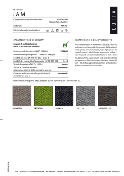
above situation through the application schema of Figure 1.
In Figure 1 two feature classes Road and RoadNetwork (basic rule 1, clause 8.3.1 of Rules for
Applications) are defined and the administrative relationship between networks and roads is described
through the RoadInNetwork association (basic rule2, clause 8.3.1 of Rules for Applications). Notice
that the cardinality of the association assures that all the roads belong to some network and that each
network collects at least one road. The two classes GM_Complex and GM_CompositeCurve of the
Spatial Schema are included in the schema in order to represent the spatial attributes of the classes
through the explicit extension and path associations between feature classes and geometric types (rule
2, clause 8.7.2 of Rules for Applications); notice that the roads are defined as simple linear geometries
using the type GM_CompositeCurve, while the only available type to describe the graphs of the
networks is GM_Complex.
The spatial relationship between the two classes can be modelled using the predefined standard
Contains association of GM_Complex, as stated in rule 2, sec. 8.7.3.3 of Rules for Applications,
5
10th EC GI & GIS Workshop, ESDI State of the Art, Warsaw, Poland, 23-25 June 2004
between the geometric types used for the spatial attributes; notice that, a composite curve related to a
complex in the Contains association must be a subcomplex of that complex and this assures the
sharing between the two geometries.
RoadNetwork
extension
1..*
1..*
ComposedOf
1..*
Road
GM_Complex
Contains
1..*
GM_CompositeCurve
path
Figure 1: The basic UML class diagram for the network application.
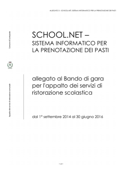
However, the above schema does not capture all the application requirements and therefore some
specific constraints must be added by the designer:
1.
linear geometry restriction: the instances of the class GM_Complex must be restricted to contain
only 0- and 1-dimensional geometric objects and not higher dimensional objects;
2.
spatial relationship enforcing: each composite curve representing the geometry of a road
belonging to a network in the RoadInNetwork association must also be associated, through the
Contains association, to the complex representing the geometry of its network.
The first constraint guarantees that GM_Complex contains curves and points, but not surfaces or
volumes, while the second constraint forces a correct instantiation of the Contains association with
respect to the RoadInNetwork association. In particular, without the second constraint, the Contains
association states the sub/superComplex relationships between the geometries involved in an instance
of the association, but it cannot force any constraint on geometries not related in the association; in the
above schema a road R belonging to more networks N1, …, Nk can have its composite curve related to
the complex of only one network Ni inside the Contains association and therefore the subcomplex
relationships could not be guaranteed for all the other networks it belongs to. Notice that, moreover,
the composite curve of a road could be linked to a complex of a network which is different from those
related to the road in the RoadInNetwork association, since the RoadInNetwork and the Contains
associations are independent.
The above constraints have been described in natural language to give their intuitive meaning,
however, ISO standards requires to write them in the Object Constraint Language (OCL), which is the
UML formalism to specify constraints, and attach them to the elements of the class diagram in order to
obtain the complete application schema, as shown in Figure 2.
6
10th EC GI & GIS Workshop, ESDI State of the Art, Warsaw, Poland, 23-25 June 2004
{ self.element->forall(a:GM_Primitive | a.dimension() <= 1)
and
self.element->forall(a:GM_Primitive | a.dimension() = 0 implies
self.element->exist(b:GM_Primitive | b.boundary()->includes(a))) },
{ self.dimension() = 1 }
extension
RoadNetwork
1..*
+net 1..*
context RoadInNetwork
inv: self.roads.path.superComplex
->includes(self.net.extension)
+roads
GM_Complex
RoadInNetwork
Contains
1..*
1..*
path
Road
GM_CompositeCurve
Figure 2: The complete UML class diagram for the network application.
How GeoUML models the application requirements.
In order to avoid the use of generic user defined OCL formulas, GeoUML embeds the two above
OCL constraints into two constructs with the following intuitive semantics:
-
the type GU_CXCurve, which is a specialization of the type GM_Complex that restricts the
primitives to be only curves and points;
-
the BelongsTo spatial association between a contained class C1 and a containing class C2,
which imposes to each instance c1 of the class C1 related to an instance c2 of the class C2 that
the geometry of c1 is a subcomplex of the geometry of c2.
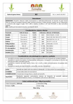
The application schema of Figure 2 is reformulated using GeoUML as shown in Figure 3. The
spatial attributes of the two feature classes are described as attributes of the classes with a geometric
domain (rule 1, clause 8.7.2 of Rules for Applications); both the geometric types have a prefix “GU_”
as required by the GeoUML application profile of the Spatial Schema, however the type GU_CPCurve
has the same semantics of GM_CompositeCurve. The UML <<BelongsTo>> stereotype transforms the
RoadInNetwork association in a BelongsTo spatial association.
7
10th EC GI & GIS Workshop, ESDI State of the Art, Warsaw, Poland, 23-25 June 2004
RoadNetwork
e xtension : GU_CXCurve
extension
1.. *
<<BelongsTo>>
RoadInNetwork
path
1.. *
Road
path : GU_CPCurve
Figure 3: The Network application schema using GeoUML.
FORMAL DEFINITION OF GEOUML
The formal definition of the GeoUML constructs follows a few general patterns, in particular the
following approaches have been applied for the definition of the main construct categories:
•
The geometric types of GeoUML are defined as a hierarchy of classes where each class
inherits directly or indirectly from a class of the Spatial Schema; the specialization is based
only on the specification of additional constraints that restrict the population of the ISO
geometric types and redefine the result type of their methods. All names of GeoUML
geometric types start with the prefix “GU_”.
•
The structural constraints are defined as logic formulas with parameters (constraint
templates), that involve the Contains and the Complex association of GM_Complex; when a
structural constraint is used in an application schema the corresponding constraint template
permits to map it to an OCL expression by completing the logic formula with the parameter
values coming from the schema. The basic logic formula for structural constraints is an
existential formula.
•
The topological constraints are defined by using constraint templates with the same approach
applied for the structural constraints, however, instead of associations of GM_Complex, they
involve the Relate functions defined on the root class GM_Object of the ISO spatial types
hierarchy. The logic formulas for topological constraints are based on existential or universal
quantifiers.
•
Layers, segmented and subregion attributes are defined in terms of the previous constructs and
correspond to predefined schema templates.
This approach is now shown in detail referring to the GU_CXCurve and BelongsTo constraint used
in the previous section.
8
10th EC GI & GIS Workshop, ESDI State of the Art, Warsaw, Poland, 23-25 June 2004
GU_CXCurve is a specialization of the type GM_Complex that restricts the primitives of a
complex to belong only to curves and points (if boundary of curves), as shown by the following OCL
constraint:
{ self.element->forall(a:GM_Primitive | a.dimension() <= 1) and
self.element->forall(a:GM_Primitive | a.dimension() = 0 implies
self.element->exist(b:GM_Primitive | b.boundary()->includes(a))) },
{ self.dimension() = 1 }
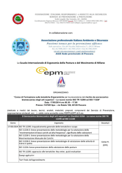
The formal definition of the BelongsTo construct is represented in Figure 4, which shows the
constraint template in terms of the corresponding UML class diagram and OCL formulas. In the
template the classes X and Y, together with their spatial attributes gx and gy, and the association A,
together with the roles rx and ry, represent the parameters of the template and, in order to obtain the
semantics of a specific constraint, they have to be substituted by schema elements when the constraint
template is used. Notice that, in performing this substitution, the spatial attributes gx and gy become
explicit associations to geometric types and the geometric type GU_Complex can be substituted by its
subtypes.
For example, this substitution, applied to the previous network application schema of Figure 3,
produces as a result the same schema which has been shown in Figure 2. This shows that the GeoUML
schema of Figure 3 is equivalent to the schema of Figure 2.
Y
gy
ry
GU_Complex
context A
inv: self.rx.gx.superComplex
->includes(self.ry.gy)
A
gx
rx
X
+superComplex
+subComplex
Contains
Figure 4: The constraint template of the BelongsTo spatial association.
CONCLUSION
In this paper the conceptual model GeoUML has been presented, that specializes the ISO
standards Spatial Schema and Rules for Applications in order to increase the usability of ISO standards
and to guide the user in the correct specification of application schemas for geographic databases.
In particular, it has been shown that:
9
10th EC GI & GIS Workshop, ESDI State of the Art, Warsaw, Poland, 23-25 June 2004
•
Given a geographic application requirement, it can be very difficult to specify it through a correct
application schema using the ISO approach directly; in particular, the example of the network
application shows that the correct application schema may contain non trivial OCL formulas, thus
leading to a specification that is not easy to read, understand and implement (Figure 2).
•
GeoUML encapsulates common OCL formulas in constraint templates with a compact graphic
representation and intuitive meaning (Figure 3), thus leading more easily to effective
implementations, since an implementation structure can be pre-designed for each GeoUML
construct.
•
Finally, it has been proved that, given a GeoUML construct applied in an application schema, the
corresponding ISO compliant UML class diagram can be automatically derived through the
templates of the formal definition of GeoUML. This allows one to implement an automatic
procedure for the derivation of an ISO compliant application schema from a GeoUML application
schema.
GeoUML has been applied for the specification of the content of the “core” geographic database in
the IntesaGIS project, which aims at defining a national geographic infrastructure in Italy.
Future work includes the definition of mapping rules from GeoUML application schemas towards
GIS systems and the realization of a XMI repository for testing schema interoperability.
BIBLIOGRAPHY
G. Amadio, C. Cannafoglia, M. Corongiu, Mario Desideri, M. Rossi, (2004) IntesaGIS: the basis for a
National Spatial Data Infrastructure, 10th EC-GI & GIS Workshop, ESDI: The State of the
Art, June 23-25, 2004, Warsaw, Poland.
A. Belussi, M. Negri, G. Pelagatti, (2004) GeoUML: an ISO TC 211 compatible data model for the
conceptual design of geographic databases, Internal report N. 2004.21, Dipartimento di
Elettronica e Informazione, Politecnico di Milano, Italy.
K. A. V. Borges, A. H. F. Laender, C. A. Davis Jr, (1999) Spatial Data Integrity Constraints in Object
Oriented Geographic Data Modeling. In Proc. of 7th ACMGIS, November 5-6, 1999, Kansas
City, USA, 1999.
E. Clementini, P. Di Felice, P. van Oosterom., (1993) A Small Set of Formal Topological
Relationships Suitable for End-User Interaction. In Advances in Spatial Databases, 3rd
International Symposium, SSD, June 23-25, 1993, Singapore, Proceedings in LNCS 692.
A. Friis-Christensen, N. Tryfona, C. S. Jensen, (2001) Requirements and Research Issues in
Geographic Data Modeling. In Proc. of 9th ACMGIS, November 9-10, 2001, Atlanta, USA.
ISO/TC 211 Geographic information/Geomatics (2002). 19107 Geographic information - Spatial
schema text for FDIS, doc. N. 1324.
ISO/TC 211, Geographic information/Geomatics (2003). 19109, Geographic Information - Rules for
application schema, text for FDIS, doc. N. 1538.
10
© Copyright 2026 Paperzz