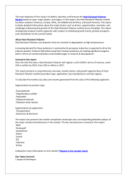
Assembly and operating instructions
Ultromat® AF and ATF
with Terminal Boxes and Pressure Sensor
A0542
Please carefully read these operating instructions before use! · Do not discard!
The operator shall be liable for any damage caused by installation or operating errors!
Technical changes reserved.
Part No. 986104
Original operating instructions (2006/42/EC)
BA UL 019 06/10 EN
ProMinent Dosiertechnik Heidelberg GmbH
Im Schuhmachergewann 5 - 11
69123 Heidelberg
Telephone: +49 6221 842-0
Fax: +49 6221 842-419
email: [email protected]
Internet: www.prominent.com
986104, 2, en_GB
© 2010
2
Table of contents
Table of contents
1
Ultromat® product identification.............................................
1.1 Ultromat® AF with Pressure Sensor product identifi‐
cation............................................................................
1.2 Ultromat® ATF with pressure sensor product identifi‐
cation............................................................................
1.3 Front view Ultromat® AF/ATF with pressure sensor.....
1.4 Plan view Ultromat® AF/ATF with pressure sensor......
1.5 About This Product.......................................................
5
5
5
5
6
6
2
Safety Chapter...................................................................... 7
2.1 Explanation of the safety information............................ 7
2.2 Correct and Proper Use................................................ 8
2.3 Users' Qualifications..................................................... 9
2.4 Information in the Event of an Emergency.................. 10
2.5 Description and Testing of the Safety Equipment....... 10
2.6 Ultromat® Safety Information...................................... 11
2.7 Sound Pressure Level................................................ 11
3
Transport and Storage of the System................................. 12
3.1 Transport and Storage of the System......................... 12
4
Information on the system...................................................
4.1 Application..................................................................
4.2 Design.........................................................................
4.3 System dimensions.....................................................
13
13
13
13
5
Design and function............................................................
5.1 Three-chamber reservoir............................................
5.2 Flush fitting.................................................................
5.3 Dry Material Feeder (ATF only)..................................
5.4 Agitators......................................................................
5.5 Power Socket for the Connection of a Conveyor (only
ATF) ...........................................................................
5.6 Terminal Box...............................................................
5.7 Crane Lifting Lugs.......................................................
5.8 Ultromat® options........................................................
5.8.1 Agitator for Chamber 3 (Agitator 3)..........................
5.8.2 Overflow Protection for the Ultromat® .....................
5.8.3 Vibrator ...................................................................
5.8.4 Discharge pipework.................................................
16
16
16
16
17
6
Assembly and Installation...................................................
6.1 Assembly....................................................................
6.2 Installation - Hydraulic................................................
6.3 Installation - Electrical.................................................
19
19
19
20
7
Controller............................................................................ 21
7.1 Terminal boxes AF/ATF.............................................. 21
8
Commissioning...................................................................
8.1 Assembly, Preparatory Work......................................
8.2 Settings for Commissioning........................................
8.3 Water Supply Setting..................................................
8.4 Calibrating the Dry Material Feeder............................
8.5 Adjusting the Concentration........................................
17
17
17
17
17
17
17
18
22
22
22
22
23
23
3
Table of contents
8.5.1 Adjusting the Concentration of the Polymer Solu‐
tion in the Ultromat® AF / ATF................................. 23
8.6 Adjusting the Capacitive Sensor................................. 24
8.7 Operation of the System............................................. 24
9
4
Operation of the System.....................................................
9.1 Prerequisites for Correct and Proper Operation.........
9.2 Feeding the Dry Material Feeder with Powdered Pol‐
ymer (ATF)..................................................................
9.3 Behaviour When Switching on Mains Power and in
the Event of Mains Power Failure...............................
9.4 Decommissioning.......................................................
9.5 Disposal......................................................................
26
26
26
26
26
27
10
Incorrect Operation of the System...................................... 28
11
Troubleshooting.................................................................. 29
11.1 Unspecified Malfunctions.......................................... 29
11.2 Sensors..................................................................... 29
12
Maintenance.......................................................................
12.1 Dry Material Feeder..................................................
12.2 Cleaning the Screen Insert in the Pressure
Reducer....................................................................
12.3 Dismantling the Cover of an Inspection Opening.....
12.4 Cleaning the Surface of the Ultromat®......................
30
30
30
30
30
13
Spare Parts and Accessories.............................................. 31
14
Appendix............................................................................. 32
15
EC Declaration of Conformity............................................. 34
16
Commissioning report......................................................... 35
17
Index................................................................................... 36
Ultromat® product identification
1
Ultromat® product identification
1.1
Ultromat® AF with Pressure Sensor product identification
Ultromat AF
Type
Reservoir
content (litre)
1.2
1037294
1037295
1037296
1037297
1037298
1037299
AF 400
AF 1000
AF 2000
AF 4000
AF 6000
AF 8000
400
1000
2000
4000
6000
8000
Ultromat® ATF with pressure sensor product identification
Ultromat ATF
1037300
1037301
1037302
1037303
1037314
1037315
Type
ATF 400
ATF 1000
ATF 2000
ATF 4000
ATF 6000
ATF 8000
400
1000
2000
4000
6000
8000
Reservoir
content (litre)
1.3
Front view Ultromat® AF/ATF with pressure sensor
1.
2.
3.
4.
5.
6.
7.
8.
9.
A0543
13.
12. 11.
10.
Fig. 1: Front view Ultromat AF/ATF with pressure sensor
1. Agitator for chamber 1
8. Overflow
2. Dry material feeder (ATF)
9. Stopcock
3. Liquid polymer connection
10. Flow meter
4. Y-Flush inlet
11. Solenoid valve
5. Agitator for chamber 2
12. Pressure reducer
6. Terminal box
13. Shut-off valve
7. Agitator for chamber 3 (optional)
5
Ultromat® product identification
1.4
Plan view Ultromat® AF/ATF with pressure sensor
1.
2.
3.
5.
4.
9.
6.
7.
8.
A0548
Fig. 2: Plan view Ultromat® AF/ATF with pressure sensor
1. Dry material feeder (ATF)
6. Discharge pipework (optional)
2. Motor for dry material feeder (ATF)
7. Inspection opening for chamber 2
3. Inspection opening for chamber 3
8. Metering pipe heating (ATF)
4. Pressure sensor level measurement chamber 3
9. Inspection opening for chamber 1
5. Shut-off valves
1.5
About This Product
The Ultromat® AF/ATF from ProMinent is a preparation system for
polyelectrolytes for connection to an external control.
The Ultromat® AF can be used in any application where synthetic
liquid polymers have to be prepared for working solutions.
The Ultromat® ATF can be used in any application where freeflowing synthetic powder polymers or liquid polymers have to be
prepared for working solutions.
6
Safety Chapter
2
Safety Chapter
Ultromat® AF/ATF
2.1
Explanation of the safety information
Introduction
These operating instructions provide information on the technical
data and functions of the product. These operating instructions pro‐
vide detailed safety information and are provided as clear step-bystep instructions.
The safety information and notes are categorised according to the
following scheme. A number of different symbols are used to
denote different situations. The symbols shown here serve only as
examples.
DANGER!
Nature and source of the danger
Consequence: Fatal or very serious injuries.
Measure to be taken to avoid this danger
Danger!
–
Denotes an immediate threatening danger. If this is
disregarded, it will result in fatal or very serious
injuries.
WARNING!
Nature and source of the danger
Possible consequence: Fatal or very serious injuries.
Measure to be taken to avoid this danger
Warning!
–
Denotes a possibly hazardous situation. If this is
disregarded, it could result in fatal or very serious
injuries.
CAUTION!
Nature and source of the danger
Possible consequence: Slight or minor injuries, mate‐
rial damage.
Measure to be taken to avoid this danger
Caution!
–
Denotes a possibly hazardous situation. If this is
disregarded, it could result in slight or minor inju‐
ries. May also be used as a warning about material
damage.
7
Safety Chapter
NOTICE!
Nature and source of the danger
Damage to the product or its surroundings
Measure to be taken to avoid this danger
Note!
–
Denotes a possibly damaging situation. If this is
disregarded, the product or an object in its vicinity
could be damaged.
Type of information
Hints on use and additional information
Source of the information, additional measures
Information!
–
2.2
Denotes hints on use and other useful information.
It does not indicate a hazardous or damaging sit‐
uation.
Correct and Proper Use
WARNING!
Danger caused by incorrect use!
Incorrect use of the Ultromat® can result in hazardous
situations.
–
–
–
–
–
–
8
The Ultromat® is only designed to produce a pol‐
ymer solution as a flocculent from powdered pol‐
ymer or liquid concentrate and with drinking water.
All other uses or a modification of the system are
only permitted with the written authorisation of
ProMinent Dosiertechnik GmbH, Heidelberg!
The system is not designed for use in areas at risk
from explosion!
The correct and proper operation of the system
cannot be guaranteed if non-genuine parts or third
party accessories are used.
Please observe the relevant national regulations
and the information provided in the operating
instructions at all phases of the system's life!
The Ultromat® may only be operated by adequately
qualified personnel
Safety Chapter
2.3
Users' Qualifications
WARNING!
Danger of injury with inadequately qualified personnel!
If inadequately qualified personnel work on the unit or
loiter in the hazard zone of the unit, this could result in
dangers that could cause serious injuries and material
damage.
–
–
All work on the unit should therefore only be con‐
ducted by qualified personnel.
Unqualified personnel should be kept away from
the hazard zone.
Activity
Training
Assembly / Installation
trained qualified personnel
Commissioning
technical experts
Operation
instructed personnel
Maintenance / Repair
Customer service department
Decommissioning / Disposal
technical experts
Troubleshooting
instructed personnel
Explanation of the terms:
n A technical expert is deemed to be a person who is able to
assess the tasks assigned to him and recognise possible haz‐
ards based on his/her technical training and experience, as
well as knowledge of pertinent regulations.
Note: A technical qualification is typically proven by the
required completion of a technical training course. The assess‐
ment of a person's technical training can also be based on sev‐
eral years of work in the relevant field.
n A qualified employee is deemed to be a person who is able to
assess the tasks assigned to him and recognise possible haz‐
ards based on his/her technical training, knowledge and experi‐
ence, as well as knowledge of pertinent regulations.
Note: The assessment of a person's technical training can also
be based on several years of work in the relevant field.
n An instructed person is deemed to be a person who has been
instructed and, if required, trained in the tasks assigned to him/
her and possible dangers that could result from improper
behaviour, as well as having been instructed in the required
protective equipment and protective measures.
n Customer service department refers to service technicians,
who have received proven training and have been authorised
by ProMinent to work on the system.
Note for the system operator
The pertinent accident prevention regulations, as well
as all other generally acknowledged safety regulations,
must be adhered to!
9
Safety Chapter
2.4
Information in the Event of an Emergency
WARNING!
Information in the Event of an Emergency
Possible consequence: Fatal or very serious injuries.
Switch off the system with the red-yellow mains switch.
External control and control cabinet!
The red-yellow mains switch is located on the opera‐
tor's side. Its precise location depends on the layout on
site. The operator is responsible for labelling this
switch.
2.5
Description and Testing of the Safety Equipment
CAUTION!
Propellers are rotating in the reservoirs!
Slight or minor injuries.
Switch off the system and only then remove the
screwed cover of an inspection opening!
1
1
1
3
2
A0094
Fig. 3: Safety equipment
Warning labels
n 1 Warning label "Warning of injury to hands"
n 2 Warning label "Warning of hazardous electrical voltage"
n 3 Warning label "Warning of hot surfaces" (ATF)
Test: Check whether the labels are still affixed and legible.
10
Safety Chapter
2.6
Ultromat® Safety Information
WARNING!
Qualification of personnel
Danger due to incorrect operation of the system
The operating personnel must be instructed by a
ProMinent service technician" (When the system is first
operated)
The operating instructions must be available by the
system!
WARNING!
Danger of electric shock!
Possible consequence: Fatal or very serious injuries
The control cabinet must always be closed during
operation.
The mains switch must be set to "0" and secured
against restart before any installation or maintenance
work can begin.
CAUTION!
Propellers are rotating in the reservoirs!
Slight or minor injuries.
Switch off the system and only then remove the
screwed cover of an inspection opening!
CAUTION!
A screw conveyor and a loosening wheel are located
under the safety guard of the dry material feeder.
Slight or minor injuries. Material damage.
Do not reach into the dry material feeder.
CAUTION!
Hot surface!
Incorrectly set heating on the metering pipe may
become hot!
Ensure that the metering pipe heating is correctly set!
2.7
Sound Pressure Level
The sound pressure level is < 70 dB (A) for powdered polymer,
according to EN ISO 11202:1997 (Acoustics - Noise emission from
machinery and equipment)
11
Transport and Storage of the System
3
3.1
Transport and Storage of the System
Transport and Storage of the System
CAUTION!
Fractures in plastic material may result from incorrect
loading
– Only move the Ultromat® system when empty
– The reservoir wall may not be subjected to point
loads
– Avoid heavy vibrations and impact loads
– Only move the system with suitable hoisting and
lifting equipment
– When using forklift trucks, use long forks, which
extend across the entire depth of the threechamber reservoir
– If a crane is used, fit the transport belts such that
shear stress is avoided, even if lifting lugs exist
– The support must be able to carry the weight of the
system
Ambient conditions for storage and transport
Permissible ambient temperature: -5 °C to +50 °C
Humidity: none
Other: No dust, no direct sunlight
12
Information on the system
4
4.1
Information on the system
Application
The Ultromat® AF/ATF manufactured by ProMinent is a polyelec‐
trolyte preparation system.
4.2
Design
Almost all commercially available polymers can be used.
Concentrations of 0.05 to 0.5 % can be set. The viscosity of the
polymer solution produced may not exceed 1500 mPas. Please
refer to the application data sheets of the polymer suppliers for
information about the viscosity of the different polymer solutions.
Adjust the flow rate of the preparation water to make full use of the
preparation chamber. Concentrations of greater than 0.5 % can
reduce the capacity of the preparation performance.
The maturing time available for the production of a polymer solu‐
tion depends on the discharge quantity and the volumetric capacity
of the Ultromat® and is approximately 60 minutes at a maximum
discharge rate.
4.3
System dimensions
System dimensions
Please refer to the dimensions sheet for the precise
dimensions of the individual Ultromat® system!
Ultromat AF
400
1000
2000
4000
6000
8000
Reservoir
content (litre)
400
1000
2000
4000
6000
8000
Chamber
volume (l)
133
333
666
1333
2000
2666
Discharge
rate (l/h)
400
1000
2000
4000
6000
8000
60
60
60
60
60
Maturing time 60
(min)
Dimensions
LxWxH (mm)
1742x905x87 2396x970x12 3095x1155x1 3081x1433x1 3936x1682x1 4377x1895x1
6
26
377
923
924
929
Net weight
(kg)
140
350
400
550
850
1150
Total weight
(kg)
540
1350
2400
4550
6850
9150
Overflow
connection
DN 40
DN 50
DN 50
DN 65
DN 65
DN 80
Discharge
connection
DN 25
DN 25
DN 32
DN 40
DN 40
DN 50
Water supply
for redilution
1"
1"
1"
1 1/2"
11/2"
2"
13
Information on the system
Ultromat AF
400
1000
2000
4000
6000
8000
Liquid con‐
DN 15
centrate pipe‐
work
DN 15
DN 15
DN 20
DN 20
DN 20
Max. water
supply
1,500 l/h
1,500 l/h
3,000 l/h
6,000 l/h
8,000 l/h
12,000 l/h
Elec. power
input
1.5 kW
2.6 kW
3.2 kW
5.0 kW
5.0 kW
9.5 kW
External fuse
25 A
25 A
25 A
25 A
25 A
40 A
Power
0.25 kW
0.55 kW
0.75 kW
1.10 kW
1.10 kW
2.20 kW
Speed (50
Hz)
750 rpm
750 rpm
750 rpm
750 rpm
750 rpm
750 rpm
Enclosure
rating
IP 55
IP 55
IP 55
IP 55
IP 55
IP 55
Power
0.18 kW
0.55 kW
0.75 kW
1.10 kW
1.10 kW
1.10 kW
Speed (50
Hz)
750 rpm
750 rpm
750 rpm
750 rpm
750 rpm
750 rpm
Enclosure
rating
IP 55
IP 55
IP 55
IP 55
IP 55
IP 55
Ultromat ATF 400
1000
2000
4000
6000
8000
Reservoir
content (litre)
400
1000
2000
4000
6000
8000
Chamber
volume (l)
133
333
666
1333
2000
2666
Discharge
rate (l/h)
400
1000
2000
4000
6000
8000
60
60
60
60
60
Agitator 1
Agitator for
chambers 2 +
3 (optional)
Maturing time 60
(min)
Dimensions
LxWxH (mm)
1742x905x91 2396x970x12 3095x1155x1 3081x1454x1 3936x1682x1 4377x1895x2
6
66
416
953
953
000
Net weight
(kg)
180
390
440
590
890
1190
Total weight
(kg)
580
1390
2440
4590
6890
9190
Overflow
connection
DN 40
DN 50
DN 50
DN 65
DN 65
DN 80
Discharge
connection
DN 25
DN 25
DN 32
DN 40
DN 40
DN 50
Water supply
for redilution
1"
1"
1"
1 1/2"
11/2"
2"
14
Information on the system
Ultromat ATF 400
1000
2000
4000
6000
8000
Liquid con‐
DN 15
centrate pipe‐
work
DN 15
DN 15
DN 20
DN 20
DN 20
Max. water
supply
1,500 l/h
1,500 l/h
3,000 l/h
6,000 l/h
8,000 l/h
12,000 l/h
Elec. power
input
1.5 kW
2.6 kW
3.2 kW
5.0 kW
5.0 kW
9.5 kW
External fuse
25 A
25 A
25 A
25 A
25 A
40 A
Power
0.25 kW
0.55 kW
0.75 kW
1.10 kW
1.10 kW
2.20 kW
Speed (50
Hz)
750 rpm
750 rpm
750 rpm
750 rpm
750 rpm
750 rpm
Enclosure
rating
IP 55
IP 55
IP 55
IP 55
IP 55
IP 55
Power
0.18 kW
0.55 kW
0.75 kW
1.10 kW
1.10 kW
1.10 kW
Speed (50
Hz)
750 rpm
750 rpm
750 rpm
750 rpm
750 rpm
750 rpm
Enclosure
rating
IP 55
IP 55
IP 55
IP 55
IP 55
IP 55
Type
TGD 18.13
TGD 18.13
TGD 18.13
TGD 30.13
TGD 30.13
TGD 38.13
Maximum
metering
output at 50
Hz
9 kg/h
9 kg/h
9 kg/h
28 kg/h
28 kg/h
55 kg/h
Agitator 1
Agitator for
chambers 2 +
3 (optional)
Powder
feeder
15
Design and function
5
Design and function
Description of the Component Assem‐
blies
5.1
Three-chamber reservoir
The PP reservoir is divided into three separate chambers, so that a
sufficient maturing time for the polymer solution can be ensured.
The division of the reservoir largely prevents the matured and
freshly prepared solution from mixing and ensures continuous dis‐
charge.
The fill level of reservoir 3 is measured by a pressure sensor (4 to
20 mA). An additional sensor is optionally available for overflow
protection.
Water pipework
5.2
The water pipework supplies the system with the required prepara‐
tion water. The pressure reduced with strainer ensures that the
correct operating pressure is limited and maintained. A solenoid
valve opens and closes the water inlet. A manual shut-off valve
also shuts off the supply of water for maintenance work.
Flush fitting
The flush fitting ensures that the polymer is intensively wetted with
preparation water.
6.
5.
1.
2.
3.
4.
A0547
Fig. 4: Flush fitting
1.
2.
3.
4.
5.
6.
5.3
Shut-off valve
Pressure reducer
Solenoid valve
Flow meter float
Control valve
Y-Flush inlet
Dry Material Feeder (ATF only)
Please refer to the separate operating instructions entitled "Dry
material feeder" in this documentation for detailed information
about the design and function of the equipment. The heating for
the metering pipe and the minimum fill level sensor for the dry
material hopper are supplied as standard.
16
Design and function
A loosening wheel is fitted directly about the feeder screw for the
continuous discharge of the powdered polymer. A metering pipe
heating unit also removes any penetrated moisture and thus pre‐
vents any caking of the powdered polymer.
5.4
Agitators
The Ultromat® is fitted with two electrical agitators as standard. A
third agitator for chamber 3 can be supplied as an option. The elec‐
trical agitators ensure that the polymer solution is gently agitated.
The electrical agitator 1 has two propellers. The agitators can start
up suddenly as soon as they are supplied with mains power!
5.5
Power Socket for the Connection of a Conveyor (only ATF)
The Ultromat® has a power socket for the connection of a con‐
veyor. The power socket is attached to the side of the terminal box
and is secured electrically by a circuit breaker.
5.6
Terminal Box
The Ultromat® has a terminal box for connection to an external
control. The control is provided by the operator.
5.7
Crane Lifting Lugs
A suitable hoisting can be attached to the four crane lifting lugs.
5.8
Ultromat® options
The following options are available for the Ultromat®.
5.8.1
Agitator for Chamber 3 (Agitator 3)
The Ultromat® is fitted with two electrical agitators as standard. A
third agitator for chamber 3 can be supplied as an option.
5.8.2
Overflow Protection for the Ultromat®
The overflow protection signals that the Ultromat® is overflowing
5.8.3
Vibrator
The vibrator helps to prevent bridging in the dry material feeder so
that the powdered polymer matures better.
17
Design and function
5.8.4
Discharge pipework
The discharge pipework serves to combine the 3 reservoir outlets.
This enables the Ultromat® to be emptied and its contents to be fed
into a drain.
18
Assembly and Installation
6
Assembly and Installation
The system is fully pre-assembled ex works. The cabling between
the terminal box and the electrical power units is fully installed.
6.1
Assembly
WARNING!
High fill weight in the system
Possible consequence: Fatal or very serious injuries.
Ensure that the position of the system can bear the
weight of the system when full.
Accessibility of the system
The system must be easily accessible at all times for
operation, maintenance and filling.
Ambient conditions:
Permissible ambient temperature: 5 ℃ to 40 ℃
The system may not be exposed to condensation or rain.
The system may not be exposed to direct sunlight.
6.2
Installation - Hydraulic
CAUTION!
Damage to the environment by the polymer solution is
possible!
Observe the safety data sheet for the polymer and
statutory regulations for disposal when draining the
discharge lines and the overflow line!
NOTICE!
Prerequisites
– The preparation water must be of drinking water
quality
– It must be free of solids and suspended particles
– Inlet water pressure: 3 bar - 5 bar
– The preparation water, overflow and discharge
lines must have the correct dimensions
The overflow and discharge lines must be laid on a gradient and be
operable without counter-pressure!
1.
Connect the line for the preparation water to the water fitting.
2.
Connect the feed pump to the discharge line.
3.
Connect up the discharge lines and lead into a suitable drain.
4.
Connect the overflow line to the overflow union and lead into
a suitable drain.
19
Assembly and Installation
6.3
Installation - Electrical
WARNING!
Danger of electric shock!
Possible consequence: Fatal or very serious injuries
–
–
–
–
The electrical installation may only be performed
by a qualified electrician
Always disconnect the system from the mains
power supply and prevent it from being re-con‐
nected before undertaking any installation work in
the electrical connections
Ensure that the cross-section of the cable is ade‐
quate
Ensure that the terminals are assigned correctly
when connecting the units
CAUTION!
Danger of malfunction!
Material damage
Ensure that the motors are rotating in the right direc‐
tion ... when connecting the agitators, powder feeder
and motor pumps
20
Controller
7
Controller
The Ultromat® AF and ATF are not equipped with a controller. The
controller is to be provided by the operator.
7.1
Terminal boxes AF/ATF
The following electrical devices are assigned to terminals in the ter‐
minal boxes:
Terminal boxes
Agitator 1, 400 VAC
Agitator 2, 400 VAC
Agitator 3, 400 VAC
Dry material feeder, 230/400 VAC, 0,18 kW
Liquid concentrate pump, 230/400 VAC, 0,37 kW
Separate fan liquid concentrate pump 230 VAC
Heating dry material feeder, 230 VAC, 28 / 34 / 45 W
Solenoid valve process water, 24 VDC, 8 W
Pressure sensor for filling level sensor, 4 ... 20 mA, 0 ... 160
mbar
n Min-contact process water (flow monitor water)
n Overflow protection
n
n
n
n
n
n
n
n
n
21
Commissioning
8
Commissioning
8.1
Assembly, Preparatory Work
CAUTION!
Initial commissioning
Possible material damage
–
–
–
Assembly
8.2
It is essential that the mechanical and electrical
connections are checked to ensure that they are
correct prior to initial commissioning
Ensure that the voltage, frequency and current
type applied in the terminal box matches the data
on the specification label
Observe the handling and set-up information con‐
tained in the previous chapters when commis‐
sioning for the first time
1.
Preparation water, discharge and overflow lines must be
fitted and checked for leakage and correct operation.
2.
Provide adequate resources in the aforementioned quality.
Settings for Commissioning
When delivered the timer relay in the terminal box is set to the fol‐
lowing default values:
Setting parameter for feed pipe
heating
Parameter
Default values
Range
Heating switch-on time
5s
1 - 10 s
Heating switch-off time
35 s
30 - 100 s
The parameters can be adapted to the process during commis‐
sioning.
8.3
Water Supply Setting
The water supply should be set to the following values.
Type
Water supply
Ultromat® 400
1500 l/h
Ultromat® 1000
1500 l/h
Ultromat® 2000
3,000 l/h
Ultromat® 4000
6,000 l/h
Ultromat® 6000
9,000 l/h
Ultromat® 8000
12,000 l/h
22
Commissioning
8.4
Calibrating the Dry Material Feeder
Required material:
n Weighing scales
n PE bag (capacity min. 500 g)
Calibration
1.
Loosen the screw couplings to dismantle the flush fitting.
2.
Hold the PE bag (capacity min. 500 g) under the metering
pipe and fill for 1 minute.
ð Weigh the volume of discharged powder. This is the
volume of "Grammes per minute when the potentiometer
is set at 100%".
3.
8.5
8.5.1
Refit the flush fitting once the powder feeder has been cali‐
brated.
Adjusting the Concentration
Adjusting the Concentration of the Polymer Solution in the Ultromat® AF / ATF
The metering rate for the dry material feeder or the concentrate
pump can be calculated from the water supply setting and the con‐
centration required. Example:
Water supply
Concentration
Metering rate of dry material
feeder / concentrate pump
1500 l/h
0,1 %
1.5 kg/h
1500 l/h
0,2 %
3.0 kg/h
1500 l/h
0,3 %
4.5 kg/h
1500 l/h
0,4 %
6.0 kg/h
1500 l/h
0,5 %
7.5 kg/h
3,000 l/h
0,1 %
3.0 kg/h
3,000 l/h
0,2 %
6.0 kg/h
3,000 l/h
0,3 %
9.0 kg/h
3,000 l/h
0,4 %
12.0 kg/h
3,000 l/h
0,5 %
15.0 kg/h
6,000 l/h
0,1 %
6.0 kg/h
6,000 l/h
0,2 %
12.0 kg/h
6,000 l/h
0,3 %
18.0 kg/h
6,000 l/h
0,4 %
24.0 kg/h
6,000 l/h
0,5 %
30.0 kg/h
AF / ATF 400, AF / ATF 1000
AF / ATF 2000
AF / ATF 4000
23
Commissioning
Water supply
Concentration
Metering rate of dry material
feeder / concentrate pump
9,000 l/h
0,1 %
9.0 kg/h
9,000 l/h
0,2 %
18.0 kg/h
9,000 l/h
0,3 %
27.0 kg/h
9,000 l/h
0,4 %
36.0 kg/h
9,000 l/h
0,5 %
45.0 kg/h
12,000 l/h
0,1 %
12.0 kg/h
12,000 l/h
0,2 %
24.0 kg/h
12,000 l/h
0,3 %
36.0 kg/h
12,000 l/h
0,4 %
48.0 kg/h
12,000 l/h
0,5 %
60.0 kg/h
AF / ATF 6000
AF / ATF 8000
8.6
Adjusting the Capacitive Sensor
The capacitive sensor for reporting a shortage of powder in the dry
material feeder must be checked and possibly adjusted.
The sensor has a yellow LED at its cable end to indicate the
switching state and also a sunken adjustment screw to adjust its
sensitivity.
The sensor is checked and adjusted in 2 steps:
With an empty dry material feeder
1.
The yellow LED on the sensor is not illuminated - the setting
is correct.
2.
The yellow LED on the sensor is illuminated:
ð Reduce the sensitivity on the adjustment screw (turn anticlockwise) until the LED goes out.
With a filled dry material feeder
1.
The yellow LED on the sensor is not illuminated - the setting
is correct.
2.
The yellow LED on the sensor is not illuminated:
ð Increase the sensitivity on the adjustment screw (turn
clockwise) until the LED is illuminated.
8.7
Operation of the System
CAUTION!
Large volumes of water of polymer solution can
escape from the system!
– Ensure that the discharge values are closed before
starting the preparation process!
24
Commissioning
CAUTION!
Monitor the operation of the system in the start-up
phase!
– Monitor in particular the correct switching operation
of the level sensor when they first reach their
respective switching points!
Prerequisites:
1.
Correct and proper assembly and installation of the system
has been checked.
2.
The discharge valves are closed.
3.
All the operating parameters have been set.
4.
All of the necessary equipment has been calibrated.
5.
Start up the system
ð the system starts up and begins the automatic prepara‐
tion process.
25
Operation of the System
9
9.1
Operation of the System
Prerequisites for Correct and Proper Operation
NOTICE!
Instructed personnel
– The system may only be operated by instructed
personnel!
Prerequisites:
9.2
Correct setting of the operating parameters.
Feeding the Dry Material Feeder with Powdered Polymer (ATF)
CAUTION!
Danger of slipping!
Mixtures of polymer and water are slippery!
–
–
Ensure that you have a secure foothold when filling
the dry material feeder
Immediately remove any spilled powdered polymer
or leaked polymer solution
If the dry material feeder is not automatically filled, the supply of
powdered polymer has to be continuously checked and refilled in
time. This can be done while the system is operational.
9.3
Behaviour When Switching on Mains Power and in the Event of Mains
Power Failure
Behaviour when switching on mains power and in the event of
mains power failure is dependent on the external control and is the
responsibility of the operator.
9.4
Decommissioning
For more than two days
26
1.
Completely empty the dry material feeder and/or liquid con‐
centrate feed.
2.
Empty the reservoir through the connections on the individual
chambers provided for this.
3.
Carefully flush the reservoirs with water.
4.
In addition, rinse the flushing fitting.
5.
Carefully flush the line between the reservoir and the feed
pump.
Operation of the System
9.5
Disposal
NOTICE!
Regulations
– Please observe the currently applicable local regu‐
lations (specifically with regard to electronic waste)
– Please also read the operating instructions for the
other equipment (dry material feeder, pumps ...)
For Germany: The cleaned used parts can be disposed of at
municipal waste collection points.
27
Incorrect Operation of the System
10
Incorrect Operation of the System
n The incorrect position of the discharge valves can result in mal‐
function
n The incorrect position of the shut-off valves in the water supply
line can result in malfunction
n Unauthorised persons must be prevented from entering or
changing operating parameters
n The maximum viscosity of 1500 mPas may not be exceeded
when setting the concentration on the external control
n The system will malfunction if the polymer supply is not refilled
28
Troubleshooting
11
Troubleshooting
CAUTION!
Danger of sudden start-up!
Possible consequence: Slight or minor injuries
–
11.1
The agitators and propeller may start up suddenly
Unspecified Malfunctions
Should a problem occur, which is not included in this list or should
a listed fault not be remedied by the suggested troubleshooting
measures, please contact ProMinent Customer Services without
delay.
11.2
Sensors
It should first be considered with every fault analysis that a capaci‐
tive proximity sensor may possibly be erroneously signalling a
fault.
29
Maintenance
12
Maintenance
The following components have to be maintained regularly. The
intervals should be based on operating conditions.
12.1
Dry Material Feeder
Inspect the dry material feeder
12.2
n Check the dry material feeder regularly during operation to
ensure that it is working correctly
n Check whether the powdered polymer is being metered cor‐
rectly
Cleaning the Screen Insert in the Pressure Reducer
Clean the screen insert at the latest when 2/3 of the throughput
surface of the screen insert is dirty.
n Manually close the shut-off valve upstream of the pressure
reducer
n Please refer to the manufacturer's instructions for further steps
12.3
Dismantling the Cover of an Inspection Opening
CAUTION!
Danger of sudden start-up!
Slight or minor injuries
–
The agitators and propeller may start up suddenly
The system must only be operated in principle when the inspection
openings are tightly screwed.
The covers may only be removed temporarily.
After the inspection work, replace all covers and screw closed!
12.4
Cleaning the Surface of the Ultromat®
CAUTION!
Material damage
Do not use cleaning agents containing solvents.
Clean the surfaces of the Ultromat® if needed, as a slippery film
can form on them over time.
30
Spare Parts and Accessories
13
Source
Spare Parts and Accessories
Spare parts and accessories can be purchased from our Customer
Service department.
31
Appendix
14
Appendix
MSR diagram: Ultromat RI flow dia‐
gram® AF/ATF with pressure sensor
A0545
Fig. 5: Ultromat RI flow diagram® AF
32
Appendix
A0546
Fig. 6: Ultromat RI flow diagram® ATF
33
EC Declaration of Conformity
15
EC Declaration of Conformity
Fig. 7: EC Declaration of Conformity
34
Commissioning report
16
Commissioning report
Commissioning report Ultromat® AF/
ATF
Ultromat® Type: AF 400, AF 1 000, AF 2 000, AF 4000, AF 6000,
AF 8000
Ultromat® Type: ATF 400, ATF 1 000, ATF 2 000, ATF 4000, ATF
6000, ATF 8000
Project number (on type plate):
Calibration settings:
Powdered polymer:
Calibrated metering capacity g/min
Water supply l/h
Liquid polymer:
Calibrated metering capacity g/min
Water supply l/h
Settings for Commissioning
Commissioning parameters
Default setting
Setting
Setting powder mode
Heating
Switch-on time 5 s
Heating switch-off time 35 s
Powdered polymer trade name:
Supplier:
Liquid polymer trade name:
Supplier
Customer:
Date:
Installation place:
35
Index
17 Index
1, 2, 3 ...
1500 mPas...........................................................
A
Accessibility..........................................................
Accessories..........................................................
Agitator.................................................................
Agitators...............................................................
Application............................................................
Assembly..............................................................
C
Calibration............................................................
Capacitive sensor.................................................
Commissioning.....................................................
Crane Lifting Lugs................................................
D
Decommissioning.................................................
Discharge pipework..............................................
Disposal...............................................................
Drinking water quality...........................................
Dry material feeder...............................................
F
Feeder screw ......................................................
Feed pipe heating................................................
flow monitor water................................................
Flush fitting...........................................................
H
Heating dry material feeder..................................
I
Incorrect operation...............................................
Inspection opening...............................................
Installation - Electrical..........................................
Installation - Hydraulic..........................................
L
Loosening wheel..................................................
M
Min-contact process water...................................
36
28
19
31
21
17
13
19
23
24
22
17
26
18
27
19
17
17
22
21
16
21
28
30
20
19
17
21
mPas.................................................................... 13
N
Nominal discharge capacity................................. 13
O
Operation............................................................. 26
Options................................................................. 17
P
Power socket........................................................ 17
PP Reservoir........................................................ 16
Propellers....................................................... 10, 29
S
Safety information.................................................. 7
Screen insert........................................................ 30
Sensor.................................................................. 24
Sensors................................................................ 29
Separate fan liquid concentrate pump................. 21
Spare parts........................................................... 31
Storage................................................................. 12
Surfaces............................................................... 30
System dimensions.............................................. 13
T
Terminal box........................................................ 17
Terminal boxes..................................................... 21
Three-chamber reservoir...................................... 16
Transport.............................................................. 12
U
Ultromat® AF/ATF front view................................. 5
Ultromat Safety Information................................. 11
Unspecified malfunctions..................................... 29
Users' Qualifications.............................................. 9
W
Warning labels..................................................... 10
Water supply........................................................ 22
© Copyright 2026 Paperzz