KeyStone Architecture
Fast Fourier Transform Coprocessor (FFTC)
User Guide
Literature Number: SPRUGS2C
December 2011
www.ti.com
Release History
Release
Date
Chapter or
Topic
Description/Comments
SPRUGS2C December 2011 As listed
• Added usage note for clarification in Block Exponent section. (Page 4-4)
• Changed left shift to right shift in Scaling section (Page 2-6)
• Corrected the format of the block exponent equation (Page 4-3)
SPRUGS2B June 2011
• Added Footnote to Table FFTC_QUEUE_X_CONTROL_REGISTER (Page 9-22)
• Added Note to Zero Pad Add Method (Page 2-4)
• Changed Footnote reference in Table FFTC_QUEUE_X_SCALING_REGISTER (Page 9-20)
• Changed register name from FTC_QUEUE_X_SCALING_AND_SHIFTING_REGISTER to
FTC_QUEUE_X_DESTINATION_QUEUE_AND_SHIFTING_REGISTER in FFT Left-Right Shift (Page 2-3)
• Changed Note for ZeroPad Multiply Method (Page 2-5)
As listed
SPRUGS2A December 2010 Chapter 2
Modified formula for LTE Frequency Shift (Page 2-5)
SPRUGS2
Initial Release
ø-ii
November 2010 All
KeyStone Architecture Fast Fourier Transform Coprocessor (FFTC) User Guide
SPRUGS2C—December 2011
Submit Documentation Feedback
Contents
www.ti.com
Contents
Release History. . . . . . . . . . . . . . . . . . . . . . . . . . . . . . . . . . . . . . . . . . . . . . . . . . . . . . . . . . . . . . . . . . . . . . . . . . . . . . . . . . . . . . . . . . . . . . . . . . . . . . . ø-ii
List of Tables . . . . . . . . . . . . . . . . . . . . . . . . . . . . . . . . . . . . . . . . . . . . . . . . . . . . . . . . . . . . . . . . . . . . . . . . . . . . . . . . . . . . . . . . . . . . . . . . . . . . . . . . . ø-vi
List of Figures . . . . . . . . . . . . . . . . . . . . . . . . . . . . . . . . . . . . . . . . . . . . . . . . . . . . . . . . . . . . . . . . . . . . . . . . . . . . . . . . . . . . . . . . . . . . . . . . . . . . . . . ø-vii
Preface
ø-ix
About This Manual. . . . . . . . . . . . . . . . . . . . . . . . . . . . . . . . . . . . . . . . . . . . . . . . . . . . . . . . . . . . . . . . . . . . . . . . . . . . . . . . ø-ix
Notational Conventions . . . . . . . . . . . . . . . . . . . . . . . . . . . . . . . . . . . . . . . . . . . . . . . . . . . . . . . . . . . . . . . . . . . . . . . . . . . ø-ix
Related Documentation from Texas Instruments . . . . . . . . . . . . . . . . . . . . . . . . . . . . . . . . . . . . . . . . . . . . . . . . . . . . ø-x
Trademarks . . . . . . . . . . . . . . . . . . . . . . . . . . . . . . . . . . . . . . . . . . . . . . . . . . . . . . . . . . . . . . . . . . . . . . . . . . . . . . . . . . . . . . . . ø-x
Chapter 1
Introduction
1.1
1.2
1.3
1.4
1.5
1-1
Purpose of the Peripheral . . . . . . . . . . . . . . . . . . . . . . . . . . . . . . . . . . . . . . . . . . . . . . . . . . . . . . . . . . . . . . . . . . . . . . 1-2
Terminology Used in This Document . . . . . . . . . . . . . . . . . . . . . . . . . . . . . . . . . . . . . . . . . . . . . . . . . . . . . . . . . . . 1-2
Features . . . . . . . . . . . . . . . . . . . . . . . . . . . . . . . . . . . . . . . . . . . . . . . . . . . . . . . . . . . . . . . . . . . . . . . . . . . . . . . . . . . . . . . 1-3
Functional Block Diagram . . . . . . . . . . . . . . . . . . . . . . . . . . . . . . . . . . . . . . . . . . . . . . . . . . . . . . . . . . . . . . . . . . . . . . 1-3
Industry Standard(s) Compliance Statement . . . . . . . . . . . . . . . . . . . . . . . . . . . . . . . . . . . . . . . . . . . . . . . . . . . . 1-4
Chapter 2
Overview
2-1
2.1 Architecture . . . . . . . . . . . . . . . . . . . . . . . . . . . . . . . . . . . . . . . . . . . . . . . . . . . . . . . . . . . . . . . . . . . . . . . . . . . . . . . . . . . 2-2
2.1.1
2.1.2
2.1.3
2.1.4
2.1.5
Configuration Registers . . . . . . . . . . . . . . . . . . . . . . . . . . . . . . . . . . . . . . . . . . . . . . . . . . . . . . . . . . . . . . . . . . . . . . . . . . . . . 2-2
FFT Engine. . . . . . . . . . . . . . . . . . . . . . . . . . . . . . . . . . . . . . . . . . . . . . . . . . . . . . . . . . . . . . . . . . . . . . . . . . . . . . . . . . . . . . . . . . 2-2
Packet DMA (PKTDMA) . . . . . . . . . . . . . . . . . . . . . . . . . . . . . . . . . . . . . . . . . . . . . . . . . . . . . . . . . . . . . . . . . . . . . . . . . . . . .2-10
FFTC Streaming Interface. . . . . . . . . . . . . . . . . . . . . . . . . . . . . . . . . . . . . . . . . . . . . . . . . . . . . . . . . . . . . . . . . . . . . . . . . . .2-10
FFTC Scheduler . . . . . . . . . . . . . . . . . . . . . . . . . . . . . . . . . . . . . . . . . . . . . . . . . . . . . . . . . . . . . . . . . . . . . . . . . . . . . . . . . . . .2-11
2.2 Interrupts. . . . . . . . . . . . . . . . . . . . . . . . . . . . . . . . . . . . . . . . . . . . . . . . . . . . . . . . . . . . . . . . . . . . . . . . . . . . . . . . . . . . .2-13
2.3 Emulation Considerations . . . . . . . . . . . . . . . . . . . . . . . . . . . . . . . . . . . . . . . . . . . . . . . . . . . . . . . . . . . . . . . . . . . . .2-13
2.4 Reset . . . . . . . . . . . . . . . . . . . . . . . . . . . . . . . . . . . . . . . . . . . . . . . . . . . . . . . . . . . . . . . . . . . . . . . . . . . . . . . . . . . . . . . . .2-13
2.4.1 Software Reset . . . . . . . . . . . . . . . . . . . . . . . . . . . . . . . . . . . . . . . . . . . . . . . . . . . . . . . . . . . . . . . . . . . . . . . . . . . . . . . . . . . . .2-13
2.4.2 Hardware Reset . . . . . . . . . . . . . . . . . . . . . . . . . . . . . . . . . . . . . . . . . . . . . . . . . . . . . . . . . . . . . . . . . . . . . . . . . . . . . . . . . . . .2-13
Chapter 3
Transmit PKTDMA Protocol-specific Descriptor Fields and Words for FFTC
3-1
3.1 Protocol-specific Flags . . . . . . . . . . . . . . . . . . . . . . . . . . . . . . . . . . . . . . . . . . . . . . . . . . . . . . . . . . . . . . . . . . . . . . . . . 3-2
3.1.1
3.1.2
3.1.3
3.1.4
Control Header . . . . . . . . . . . . . . . . . . . . . . . . . . . . . . . . . . . . . . . . . . . . . . . . . . . . . . . . . . . . . . . . . . . . . . . . . . . . . . . . . . . . . 3-2
Local Configuration Words . . . . . . . . . . . . . . . . . . . . . . . . . . . . . . . . . . . . . . . . . . . . . . . . . . . . . . . . . . . . . . . . . . . . . . . . . . 3-3
DFT Size List Configuration Words . . . . . . . . . . . . . . . . . . . . . . . . . . . . . . . . . . . . . . . . . . . . . . . . . . . . . . . . . . . . . . . . . . . 3-3
Protocol-specific Pass-through Words . . . . . . . . . . . . . . . . . . . . . . . . . . . . . . . . . . . . . . . . . . . . . . . . . . . . . . . . . . . . . . . 3-3
Chapter 4
Receive PKTDMA Descriptor and Packet For FFTC
4-1
4.1 Side Information . . . . . . . . . . . . . . . . . . . . . . . . . . . . . . . . . . . . . . . . . . . . . . . . . . . . . . . . . . . . . . . . . . . . . . . . . . . . . . . 4-2
4.1.1
4.1.2
4.1.3
4.1.4
4.1.5
Block Exponent . . . . . . . . . . . . . . . . . . . . . . . . . . . . . . . . . . . . . . . . . . . . . . . . . . . . . . . . . . . . . . . . . . . . . . . . . . . . . . . . . . . . . 4-3
Clip Detection . . . . . . . . . . . . . . . . . . . . . . . . . . . . . . . . . . . . . . . . . . . . . . . . . . . . . . . . . . . . . . . . . . . . . . . . . . . . . . . . . . . . . . 4-4
Error Indication . . . . . . . . . . . . . . . . . . . . . . . . . . . . . . . . . . . . . . . . . . . . . . . . . . . . . . . . . . . . . . . . . . . . . . . . . . . . . . . . . . . . . 4-4
Destination Tag . . . . . . . . . . . . . . . . . . . . . . . . . . . . . . . . . . . . . . . . . . . . . . . . . . . . . . . . . . . . . . . . . . . . . . . . . . . . . . . . . . . . . 4-4
Source Id . . . . . . . . . . . . . . . . . . . . . . . . . . . . . . . . . . . . . . . . . . . . . . . . . . . . . . . . . . . . . . . . . . . . . . . . . . . . . . . . . . . . . . . . . . . 4-4
SPRUGS2C—December 2011
Submit Documentation Feedback
KeyStone Architecture Fast Fourier Transform Coprocessor (FFTC) User Guide
ø-iii
Contents
www.ti.com
4.1.6 Flow Id . . . . . . . . . . . . . . . . . . . . . . . . . . . . . . . . . . . . . . . . . . . . . . . . . . . . . . . . . . . . . . . . . . . . . . . . . . . . . . . . . . . . . . . . . . . . . 4-4
4.2 Pass-through Fields . . . . . . . . . . . . . . . . . . . . . . . . . . . . . . . . . . . . . . . . . . . . . . . . . . . . . . . . . . . . . . . . . . . . . . . . . . . . 4-4
Chapter 5
Endian Mode Support
5-1
Halt Modes
6-1
Errors
7-1
Chapter 6
Chapter 7
7.1 Types of Errors . . . . . . . . . . . . . . . . . . . . . . . . . . . . . . . . . . . . . . . . . . . . . . . . . . . . . . . . . . . . . . . . . . . . . . . . . . . . . . . . . 7-2
7.1.1
7.1.2
7.1.3
7.1.4
Configuration Error . . . . . . . . . . . . . . . . . . . . . . . . . . . . . . . . . . . . . . . . . . . . . . . . . . . . . . . . . . . . . . . . . . . . . . . . . . . . . . . . . 7-2
Receive Buffer Starvation Error . . . . . . . . . . . . . . . . . . . . . . . . . . . . . . . . . . . . . . . . . . . . . . . . . . . . . . . . . . . . . . . . . . . . . . 7-2
EOP Error . . . . . . . . . . . . . . . . . . . . . . . . . . . . . . . . . . . . . . . . . . . . . . . . . . . . . . . . . . . . . . . . . . . . . . . . . . . . . . . . . . . . . . . . . . . 7-2
Invalid Configuration Length Error. . . . . . . . . . . . . . . . . . . . . . . . . . . . . . . . . . . . . . . . . . . . . . . . . . . . . . . . . . . . . . . . . . . 7-2
7.2 FFTC Error Conditions Behavior. . . . . . . . . . . . . . . . . . . . . . . . . . . . . . . . . . . . . . . . . . . . . . . . . . . . . . . . . . . . . . . . . 7-4
Chapter 8
Interrupt Servicing
8-1
Registers
9-1
Chapter 9
9.1
9.2
9.3
9.4
9.5
9.6
9.7
9.8
9.9
Peripheral ID Register (FFTC_PID_REGISTER) . . . . . . . . . . . . . . . . . . . . . . . . . . . . . . . . . . . . . . . . . . . . . . . . . . . . 9-5
Configuration Register (FFTC_CONFIGURATION_REGISTER) . . . . . . . . . . . . . . . . . . . . . . . . . . . . . . . . . . . . . 9-6
Control Register (FFTC_CONTROL_REGISTER) . . . . . . . . . . . . . . . . . . . . . . . . . . . . . . . . . . . . . . . . . . . . . . . . . . . 9-7
Status Register (FFTC_STATUS_REGISTER) . . . . . . . . . . . . . . . . . . . . . . . . . . . . . . . . . . . . . . . . . . . . . . . . . . . . . . 9-8
Emulation Control Register (FFTC_EMULATION_CONTROL_REGISTER) . . . . . . . . . . . . . . . . . . . . . . . . . . . 9-9
Error Interrupt Status Register (FFTC_ERROR_INTERRUPT_RAW_STATUS_REGISTER). . . . . . . . . . . . .9-10
Error Interrupt Set Register (FFTC_ERROR_INTERRUPT_SET_REGISTER) . . . . . . . . . . . . . . . . . . . . . . . . . .9-11
Error Interrupt Clear Register (FFTC_ERROR_INTERRUPT_CLEAR_REGISTER) . . . . . . . . . . . . . . . . . . . . .9-12
Error Interrupt Enabled Status Register
(FFTC_ERROR_INTERRUPT_ENABLED_STATUS_REGISTER) . . . . . . . . . . . . . . . . . . . . . . . . . . . . . . . . .9-13
9.10 Error Interrupt Enable Register (FFTC_ERROR_INTERRUPT_ENABLE_REGISTER). . . . . . . . . . . . . . . . .9-14
9.11 Error Interrupt Enable Clear Register (FFTC_ERROR_INTERRUPT_ENABLE_CLEAR_REGISTER) . . .9-15
9.12 Halt on Error Enable Register (FFTC_HALT_ON_ERROR_REGISTER). . . . . . . . . . . . . . . . . . . . . . . . . . . . .9-16
9.13 End of Interrupt Register (FFTC_END_OF_INTERRUPT_REGISTER) . . . . . . . . . . . . . . . . . . . . . . . . . . . . . .9-17
9.14 Queue Clipping Detect Register (FFTC_QUEUE_X_CLIPPING_DETECT_REGISTER) . . . . . . . . . . . . . .9-18
9.15 Queue Destination Queue And Shifting Register
(FFTC_QUEUE_X_DESTINATION_QUEUE_AND_SHIFTING_REGISTER). . . . . . . . . . . . . . . . . . . . . . .9-19
9.16 Queue Scaling Register (FFTC_QUEUE_X_SCALING_REGISTER) . . . . . . . . . . . . . . . . . . . . . . . . . . . . . . . .9-20
9.17 Queue Cyclic Prefix Register (FFTC_QUEUE_X_CYCLIC_PREFIX_REGISTER) . . . . . . . . . . . . . . . . . . . . .9-21
9.18 Queue Control Register (FFTC_QUEUE_X_CONTROL_REGISTER) . . . . . . . . . . . . . . . . . . . . . . . . . . . . . . .9-22
9.19 Queue LTE Frequency Shift Register (FFTC_QUEUE_X_LTE_FREQUENCY_SHIFT_REGISTER) . . . . .9-23
9.20 DFT Size List Group Register (FFTC_DFT_SIZE_LIST_GROUP_X_REGISTER) . . . . . . . . . . . . . . . . . . . . .9-24
9.21 Destination Queue and Shifting Status Register
(FFTC_BLOCK_X_DESTINATION_QUEUE_AND_SHIFTING_REGISTER) . . . . . . . . . . . . . . . . . . . . . . .9-25
9.22 Scaling Status Register (FFTC_BLOCK_X_SCALING_REGISTER) . . . . . . . . . . . . . . . . . . . . . . . . . . . . . . . . .9-26
9.23 Cyclic Prefix Status Register (FFTC_BLOCK_X_CYCLIC_PREFIX_REGISTER) . . . . . . . . . . . . . . . . . . . . . .9-27
9.24 Control Status Register (FFTC_BLOCK_X_CONTROL_REGISTER). . . . . . . . . . . . . . . . . . . . . . . . . . . . . . . .9-28
ø-iv
KeyStone Architecture Fast Fourier Transform Coprocessor (FFTC) User Guide
SPRUGS2C—December 2011
Submit Documentation Feedback
Contents
www.ti.com
9.25 LTE Frequency Shift Status Register (FFTC_BLOCK_X_LTE_FREQUENCY_SHIFT_REGISTER). . . . . .9-29
9.26 Packet Size Status Register (FFTC_BLOCK_X_PACKET_SIZE_STATUS_REGISTER) . . . . . . . . . . . . . . . .9-30
9.27 Tag Status Register (FFTC_BLOCK_X_TAG_STATUS_REGISTER) . . . . . . . . . . . . . . . . . . . . . . . . . . . . . . . .9-31
Index
SPRUGS2C—December 2011
Submit Documentation Feedback
IX-1
KeyStone Architecture Fast Fourier Transform Coprocessor (FFTC) User Guide
ø-v
List of Tables
www.ti.com
List of Tables
Table 1-1
Table 2-1
Table 2-2
Table 2-3
Table 3-1
Table 3-2
Table 3-3
Table 5-1
Table 5-2
Table 7-1
Table 7-2
Table 7-3
Table 9-1
Table 9-2
Table 9-3
Table 9-4
Table 9-5
Table 9-6
Table 9-7
Table 9-8
Table 9-9
Table 9-10
Table 9-11
Table 9-12
Table 9-13
Table 9-14
Table 9-15
Table 9-16
Table 9-17
Table 9-18
Table 9-19
Table 9-20
Table 9-21
Table 9-22
Table 9-23
Table 9-24
Table 9-25
Table 9-26
Table 9-27
Table 9-28
ø-vi
Terminology . . . . . . . . . . . . . . . . . . . . . . . . . . . . . . . . . . . . . . . . . . . . . . . . . . . . . . . . . . . . . . . . . . . . . . . . . . . . . . . . . . . . . . . . . . . . . . . . . . . . 1-2
Maximum Allowed Value for 'ZERO_PAD_VAL' in Multiply Mode . . . . . . . . . . . . . . . . . . . . . . . . . . . . . . . . . . . . . . . . . . . . . . . . . . 2-5
Supported Block Sizes . . . . . . . . . . . . . . . . . . . . . . . . . . . . . . . . . . . . . . . . . . . . . . . . . . . . . . . . . . . . . . . . . . . . . . . . . . . . . . . . . . . . . . . . . . . 2-7
Index and Number of Stages for Supported Block Sizes . . . . . . . . . . . . . . . . . . . . . . . . . . . . . . . . . . . . . . . . . . . . . . . . . . . . . . . . . . . 2-8
Bit Description for TX PS Flags . . . . . . . . . . . . . . . . . . . . . . . . . . . . . . . . . . . . . . . . . . . . . . . . . . . . . . . . . . . . . . . . . . . . . . . . . . . . . . . . . . . 3-2
PS Control Header Word . . . . . . . . . . . . . . . . . . . . . . . . . . . . . . . . . . . . . . . . . . . . . . . . . . . . . . . . . . . . . . . . . . . . . . . . . . . . . . . . . . . . . . . . . 3-2
PS Local Configuration Words. . . . . . . . . . . . . . . . . . . . . . . . . . . . . . . . . . . . . . . . . . . . . . . . . . . . . . . . . . . . . . . . . . . . . . . . . . . . . . . . . . . . 3-3
Little-endian Word Format. . . . . . . . . . . . . . . . . . . . . . . . . . . . . . . . . . . . . . . . . . . . . . . . . . . . . . . . . . . . . . . . . . . . . . . . . . . . . . . . . . . . . . . 5-1
Big-endian Word Format . . . . . . . . . . . . . . . . . . . . . . . . . . . . . . . . . . . . . . . . . . . . . . . . . . . . . . . . . . . . . . . . . . . . . . . . . . . . . . . . . . . . . . . . 5-2
Configuration Errors . . . . . . . . . . . . . . . . . . . . . . . . . . . . . . . . . . . . . . . . . . . . . . . . . . . . . . . . . . . . . . . . . . . . . . . . . . . . . . . . . . . . . . . . . . . . . 7-2
Unflagged Configuration Errors . . . . . . . . . . . . . . . . . . . . . . . . . . . . . . . . . . . . . . . . . . . . . . . . . . . . . . . . . . . . . . . . . . . . . . . . . . . . . . . . . . 7-3
FFTC Errors . . . . . . . . . . . . . . . . . . . . . . . . . . . . . . . . . . . . . . . . . . . . . . . . . . . . . . . . . . . . . . . . . . . . . . . . . . . . . . . . . . . . . . . . . . . . . . . . . . . . . . 7-4
Register Map . . . . . . . . . . . . . . . . . . . . . . . . . . . . . . . . . . . . . . . . . . . . . . . . . . . . . . . . . . . . . . . . . . . . . . . . . . . . . . . . . . . . . . . . . . . . . . . . . . . . 9-1
Peripheral ID Register (FFTC_PID_REGISTER) Field Description . . . . . . . . . . . . . . . . . . . . . . . . . . . . . . . . . . . . . . . . . . . . . . . . . . . . 9-5
FFTC_CONFIGURATION_REGISTER Field Description. . . . . . . . . . . . . . . . . . . . . . . . . . . . . . . . . . . . . . . . . . . . . . . . . . . . . . . . . . . . . . 9-6
FFTC_CONTROL_REGISTER Field Description . . . . . . . . . . . . . . . . . . . . . . . . . . . . . . . . . . . . . . . . . . . . . . . . . . . . . . . . . . . . . . . . . . . . . 9-7
FFTC_STATUS_REGISTER Field Description . . . . . . . . . . . . . . . . . . . . . . . . . . . . . . . . . . . . . . . . . . . . . . . . . . . . . . . . . . . . . . . . . . . . . . . 9-8
FFTC_EMULATION_CONTROL_REGISTER Field Description. . . . . . . . . . . . . . . . . . . . . . . . . . . . . . . . . . . . . . . . . . . . . . . . . . . . . . . . 9-9
FFTC_ERROR_INTERRUPT_RAW_STATUS_REGISTER Field Description . . . . . . . . . . . . . . . . . . . . . . . . . . . . . . . . . . . . . . . . . . . . 9-10
FFTC_ERROR_INTERRUPT_SET_REGISTER Field Description . . . . . . . . . . . . . . . . . . . . . . . . . . . . . . . . . . . . . . . . . . . . . . . . . . . . . . 9-11
FFTC_ERROR_INTERRUPT_CLEAR_REGISTER Field Description . . . . . . . . . . . . . . . . . . . . . . . . . . . . . . . . . . . . . . . . . . . . . . . . . . . 9-12
FFTC_ERROR_INTERRUPT_ENABLED_STATUS_REGISTER Field Description. . . . . . . . . . . . . . . . . . . . . . . . . . . . . . . . . . . . . . . . 9-13
FFTC_ERROR_INTERRUPT_ENABLE_REGISTER Field Description . . . . . . . . . . . . . . . . . . . . . . . . . . . . . . . . . . . . . . . . . . . . . . . . . . 9-14
FFTC_ERROR_INTERRUPT_ENABLE_CLEAR_REGISTER Field Description . . . . . . . . . . . . . . . . . . . . . . . . . . . . . . . . . . . . . . . . . . 9-15
FFTC_HALT_ON_ERROR_REGISTER Field Description . . . . . . . . . . . . . . . . . . . . . . . . . . . . . . . . . . . . . . . . . . . . . . . . . . . . . . . . . . . . 9-16
FFTC_END_OF_INTERRUPT_REGISTER Field Description . . . . . . . . . . . . . . . . . . . . . . . . . . . . . . . . . . . . . . . . . . . . . . . . . . . . . . . . . 9-17
FFTC_QUEUE_X_CLIPPING_DETECT_REGISTER Field Description . . . . . . . . . . . . . . . . . . . . . . . . . . . . . . . . . . . . . . . . . . . . . . . . . 9-18
FFTC_QUEUE_X_DESTINATION_QUEUE_AND_SHIFTING_REGISTER Field Description . . . . . . . . . . . . . . . . . . . . . . . . . . . . . 9-19
FFTC_QUEUE_X_SCALING_REGISTER Field Description . . . . . . . . . . . . . . . . . . . . . . . . . . . . . . . . . . . . . . . . . . . . . . . . . . . . . . . . . . 9-20
FFTC_QUEUE_X_CYCLIC_PREFIX_REGISTER Field Description . . . . . . . . . . . . . . . . . . . . . . . . . . . . . . . . . . . . . . . . . . . . . . . . . . . . 9-21
FFTC_QUEUE_X_CONTROL_REGISTER Field Description . . . . . . . . . . . . . . . . . . . . . . . . . . . . . . . . . . . . . . . . . . . . . . . . . . . . . . . . . 9-22
FFTC_QUEUE_X_LTE_FREQUENCY_SHIFT_REGISTER Field Description . . . . . . . . . . . . . . . . . . . . . . . . . . . . . . . . . . . . . . . . . . . 9-23
FFTC_DFT_SIZE_LIST_GROUP_X_REGISTER Field Description . . . . . . . . . . . . . . . . . . . . . . . . . . . . . . . . . . . . . . . . . . . . . . . . . . . . 9-24
FFTC_BLOCK_X_DESTINATION_QUEUE_REGISTER Field Description . . . . . . . . . . . . . . . . . . . . . . . . . . . . . . . . . . . . . . . . . . . . . 9-25
FFTC_BLOCK_X_SCALING_REGISTER Field Description. . . . . . . . . . . . . . . . . . . . . . . . . . . . . . . . . . . . . . . . . . . . . . . . . . . . . . . . . . . 9-26
FFTC_BLOCK_X_CYCLIC_PREFIX_REGISTER Field Description . . . . . . . . . . . . . . . . . . . . . . . . . . . . . . . . . . . . . . . . . . . . . . . . . . . . 9-27
FFTC_BLOCK_X_CONTROL_REGISTER Field Description. . . . . . . . . . . . . . . . . . . . . . . . . . . . . . . . . . . . . . . . . . . . . . . . . . . . . . . . . . 9-28
FFTC_BLOCK_X_LTE_FREQUENCY_SHIFT_REGISTER Field Description. . . . . . . . . . . . . . . . . . . . . . . . . . . . . . . . . . . . . . . . . . . . 9-29
FFTC_BLOCK_X_PACKET_SIZE_STATUS_REGISTER Field Description . . . . . . . . . . . . . . . . . . . . . . . . . . . . . . . . . . . . . . . . . . . . . 9-30
FFTC_BLOCK_X_TAG_STATUS_REGISTER Field Description . . . . . . . . . . . . . . . . . . . . . . . . . . . . . . . . . . . . . . . . . . . . . . . . . . . . . . 9-31
KeyStone Architecture Fast Fourier Transform Coprocessor (FFTC) User Guide
SPRUGS2C—December 2011
Submit Documentation Feedback
List of Figures
www.ti.com
List of Figures
Figure 1-1
Figure 2-1
Figure 2-2
Figure 2-3
Figure 2-4
Figure 2-5
Figure 3-1
Figure 4-1
Figure 4-2
Figure 9-1
Figure 9-2
Figure 9-3
Figure 9-4
Figure 9-5
Figure 9-6
Figure 9-7
Figure 9-8
Figure 9-9
Figure 9-10
Figure 9-11
Figure 9-12
Figure 9-13
Figure 9-14
Figure 9-15
Figure 9-16
Figure 9-17
Figure 9-18
Figure 9-19
Figure 9-20
Figure 9-21
Figure 9-22
Figure 9-23
Figure 9-24
Figure 9-25
Figure 9-26
Figure 9-27
FFTC Block Diagram . . . . . . . . . . . . . . . . . . . . . . . . . . . . . . . . . . . . . . . . . . . . . . . . . . . . . . . . . . . . . . . . . . . . . . . . . . . . . . . . . . . . . . . . . . . . . 1-3
FFT Engine . . . . . . . . . . . . . . . . . . . . . . . . . . . . . . . . . . . . . . . . . . . . . . . . . . . . . . . . . . . . . . . . . . . . . . . . . . . . . . . . . . . . . . . . . . . . . . . . . . . . . . 2-3
FFTC Variable Shift Example with 1200 Carriers . . . . . . . . . . . . . . . . . . . . . . . . . . . . . . . . . . . . . . . . . . . . . . . . . . . . . . . . . . . . . . . . . . . 2-4
Scaling . . . . . . . . . . . . . . . . . . . . . . . . . . . . . . . . . . . . . . . . . . . . . . . . . . . . . . . . . . . . . . . . . . . . . . . . . . . . . . . . . . . . . . . . . . . . . . . . . . . . . . . . . . 2-6
Cyclic Prefix Addition . . . . . . . . . . . . . . . . . . . . . . . . . . . . . . . . . . . . . . . . . . . . . . . . . . . . . . . . . . . . . . . . . . . . . . . . . . . . . . . . . . . . . . . . . . . . 2-9
Cyclic Prefix Removal . . . . . . . . . . . . . . . . . . . . . . . . . . . . . . . . . . . . . . . . . . . . . . . . . . . . . . . . . . . . . . . . . . . . . . . . . . . . . . . . . . . . . . . . . . . 2-11
Organization of the PKTDMA Protocol-Specific Words for FFTC. . . . . . . . . . . . . . . . . . . . . . . . . . . . . . . . . . . . . . . . . . . . . . . . . . . . 3-2
PKTDMA RX Payload Format with SUPPRESS_SIDE_INFO Off . . . . . . . . . . . . . . . . . . . . . . . . . . . . . . . . . . . . . . . . . . . . . . . . . . . . . . 4-2
PKTDMA RX Payload Format with SUPPRESS_SIDE_INFO Set . . . . . . . . . . . . . . . . . . . . . . . . . . . . . . . . . . . . . . . . . . . . . . . . . . . . . . 4-3
Peripheral ID Register (FFTC_PID_REGISTER). . . . . . . . . . . . . . . . . . . . . . . . . . . . . . . . . . . . . . . . . . . . . . . . . . . . . . . . . . . . . . . . . . . . . . 9-5
Configuration Register (FFTC_CONFIGURATION_REGISTER) . . . . . . . . . . . . . . . . . . . . . . . . . . . . . . . . . . . . . . . . . . . . . . . . . . . . . . . 9-6
Control Register (FFTC_CONTROL_REGISTER). . . . . . . . . . . . . . . . . . . . . . . . . . . . . . . . . . . . . . . . . . . . . . . . . . . . . . . . . . . . . . . . . . . . . 9-7
Status Register (FFTC_STATUS_REGISTER) . . . . . . . . . . . . . . . . . . . . . . . . . . . . . . . . . . . . . . . . . . . . . . . . . . . . . . . . . . . . . . . . . . . . . . . . 9-8
Emulation Control Register (FFTC_EMULATION_CONTROL_REGISTER) . . . . . . . . . . . . . . . . . . . . . . . . . . . . . . . . . . . . . . . . . . . . 9-9
Error Interrupt Status Register (FFTC_ERROR_INTERRUPT_RAW_STATUS_REGISTER) . . . . . . . . . . . . . . . . . . . . . . . . . . . . . . 9-10
Error Interrupt Set Register (FFTC_ERROR_INTERRUPT_SET_REGISTER) . . . . . . . . . . . . . . . . . . . . . . . . . . . . . . . . . . . . . . . . . . . 9-11
Error Interrupt Clear Register (FFTC_ERROR_INTERRUPT_CLEAR_REGISTER) . . . . . . . . . . . . . . . . . . . . . . . . . . . . . . . . . . . . . . 9-12
Error Interrupt Enabled Status Register (FFTC_ERROR_INTERRUPT_ENABLED_STATUS_REGISTER) . . . . . . . . . . . . . . . . . 9-13
Error Interrupt Enable Register (FFTC_ERROR_INTERRUPT_ENABLE_REGISTER) . . . . . . . . . . . . . . . . . . . . . . . . . . . . . . . . . . . 9-14
Error Interrupt Enable Clear Register (FFTC_ERROR_INTERRUPT_ENABLE_CLEAR_REGISTER) . . . . . . . . . . . . . . . . . . . . . . 9-15
Halt on Error Enable Register (FFTC_HALT_ON_ERROR_REGISTER) . . . . . . . . . . . . . . . . . . . . . . . . . . . . . . . . . . . . . . . . . . . . . . . 9-16
End of Interrupt Register (FFTC_END_OF_INTERRUPT_REGISTER) . . . . . . . . . . . . . . . . . . . . . . . . . . . . . . . . . . . . . . . . . . . . . . . . 9-17
Queue Clipping Detect Register (FFTC_QUEUE_X_CLIPPING_DETECT_REGISTER) . . . . . . . . . . . . . . . . . . . . . . . . . . . . . . . . . 9-18
Queue Destination Queue and Shifting Register
(FFTC_QUEUE_X_DESTINATION_QUEUE_AND_SHIFTING_REGISTER) . . . . . . . . . . . . . . . . . . . . . . . . . . . . . . . . . . . . . . . . . . . 9-19
Queue Scaling Register (FFTC_QUEUE_X_SCALING_REGISTER) . . . . . . . . . . . . . . . . . . . . . . . . . . . . . . . . . . . . . . . . . . . . . . . . . . . 9-20
Queue Cyclic Prefix Register (FFTC_QUEUE_X_CYCLIC_PREFIX_REGISTER) . . . . . . . . . . . . . . . . . . . . . . . . . . . . . . . . . . . . . . . . 9-21
Queue Control Register (FFTC_QUEUE_X_CONTROL_REGISTER). . . . . . . . . . . . . . . . . . . . . . . . . . . . . . . . . . . . . . . . . . . . . . . . . . 9-22
Queue LTE Frequency Shift Register (FFTC_QUEUE_X_LTE_FREQUENCY_SHIFT_REGISTER). . . . . . . . . . . . . . . . . . . . . . . . 9-23
DFT Size List Group Register (FFTC_DFT_SIZE_LIST_GROUP_X_REGISTER) . . . . . . . . . . . . . . . . . . . . . . . . . . . . . . . . . . . . . . . . 9-24
Destination Queue and Shifting Status Register (FFTC_BLOCK_X_DESTINATION_QUEUE_REGISTER) . . . . . . . . . . . . . . 9-25
Scaling Status Register (FFTC_BLOCK_X_SCALING_REGISTER). . . . . . . . . . . . . . . . . . . . . . . . . . . . . . . . . . . . . . . . . . . . . . . . . . . . 9-26
Cyclic Prefix Status Register (FFTC_BLOCK_X_CYCLIC_PREFIX_REGISTER). . . . . . . . . . . . . . . . . . . . . . . . . . . . . . . . . . . . . . . . . 9-27
Control Status Register (FFTC_BLOCK_X_CONTROL_REGISTER) . . . . . . . . . . . . . . . . . . . . . . . . . . . . . . . . . . . . . . . . . . . . . . . . . . 9-28
LTE Frequency Shift Status Register (FFTC_BLOCK_X_LTE_FREQUENCY_SHIFT_REGISTER) . . . . . . . . . . . . . . . . . . . . . . . . 9-29
Packet Size Status Register (FFTC_BLOCK_X_PACKET_SIZE_STATUS_REGISTER) . . . . . . . . . . . . . . . . . . . . . . . . . . . . . . . . . . 9-30
Tag Status Register (FFTC_BLOCK_X_TAG_STATUS_REGISTER) . . . . . . . . . . . . . . . . . . . . . . . . . . . . . . . . . . . . . . . . . . . . . . . . . . . 9-31
SPRUGS2C—December 2011
Submit Documentation Feedback
KeyStone Architecture Fast Fourier Transform Coprocessor (FFTC) User Guide
ø-vii
List of Figures
ø-viii
KeyStone Architecture Fast Fourier Transform Coprocessor (FFTC) User Guide
www.ti.com
SPRUGS2C—December 2011
Submit Documentation Feedback
Preface
About This Manual
This user guide describes the functionality and operation of the Fast Fourier Transform
Coprocessor (FFTC) module. The FFTC module is accessible across all the C66x cores
on a multicore DSP. This module can be used to accelerate the FFT and IFFT
computations that are required in various applications like LTE systems.
Notational Conventions
This document uses the following conventions:
• Commands and keywords are in boldface font.
• Arguments for which you supply values are in italic font.
• Terminal sessions and information the system displays are in screen font.
• Information you must enter is in boldface screen font.
• Elements in square brackets ([ ]) are optional.
Notes use the following conventions:
Note—Means reader take note. Notes contain helpful suggestions or references
to material not covered in the publication.
The information in a caution or a warning is provided for your protection. Please read
each caution and warning carefully.
CAUTION—Indicates the possibility of service interruption if precautions are
not taken.
WARNING—Indicates the possibility of damage to equipment if precautions are
not taken.
SPRUGS2C—December 2011
Submit Documentation Feedback
KeyStone Architecture Fast Fourier Transform Coprocessor (FFTC) User Guide
ø-ix
Preface
www.ti.com
Related Documentation from Texas Instruments
AIF1-to-AIF2 Antenna Interface Migration Guide for KeyStone Devices
SPRABH8
Connecting AIF2 with FFTC
SPRABF3
Antenna Interface 2 (AIF2) for KeyStone Devices User Guide
SPRUGV7
C66x CorePac User Guide
SPRUGW0
Enhanced Direct Memory Access 3 (EDMA3) for KeyStone Devices User Guide
SPRUGS5
Multicore Navigator for KeyStone Devices User Guide
SPRUGR9
Turbo Decoder Coprocessor 3 (TCP3d) for KeyStone Devices User Guide
SPRUGS0
Turbo Encoder Coprocessor 3 (TCP3e) for KeyStone Devices User Guide
SPRUGS1
Trademarks
TMS320C66x and C66x are trademarks of Texas Instruments Incorporated.
All other brand names and trademarks mentioned in this document are the property of Texas Instruments
Incorporated or their respective owners, as applicable.
ø-x
KeyStone Architecture Fast Fourier Transform Coprocessor (FFTC) User Guide
SPRUGS2C—December 2011
Submit Documentation Feedback
Chapter 1
Introduction
IMPORTANT NOTE—The information in this document should be used in conjunction
with information in the device-specific Keystone Architecture data manual that applies
to the part number of your device.
1.1
1.2
1.3
1.4
1.5
SPRUGS2C—December 2011
Submit Documentation Feedback
"Purpose of the Peripheral" on page 1-2
"Terminology Used in This Document" on page 1-2
"Features" on page 1-3
"Functional Block Diagram" on page 1-3
"Industry Standard(s) Compliance Statement" on page 1-4
KeyStone Architecture Fast Fourier Transform Coprocessor (FFTC) User Guide
1-1
1.1 Purpose of the Peripheral
Chapter 1—Introduction
www.ti.com
1.1 Purpose of the Peripheral
This document describes the functionality and operation of the Fast Fourier Transform
Coprocessor (FFTC) module. The FFTC module is accessible across all the C66x cores
on a multicore DSP. This module can be used to accelerate the FFT and IFFT
computations that are required in various applications like LTE systems.
1.2 Terminology Used in This Document
Table 1-1
1-2
Terminology
Acronym
Description
AIF
Antenna Interface
CPPI
Communication Port Programming Interface (Packet DMA)
EDMA3
Enhanced Direct Memory Access version 3
FFT
Fast Fourier Transform
FFTC
FFT Coprocessor
IFFT
Inverse Fast Fourier Transform
LTE
“Long Term Evolution” term to describe the first 3GPP OFDM standard
PKTDMA
Packet DMA (CPPI)
PS
Protocol-specific
QM
Queue Manager
RB
LTE resource block – a set of 12 subcarriers as defined in the LTE standard
TCP3
Turbo coprocessor version 3
KeyStone Architecture Fast Fourier Transform Coprocessor (FFTC) User Guide
SPRUGS2C—December 2011
Submit Documentation Feedback
1.3 Features
Chapter 1—Introduction
www.ti.com
1.3 Features
The FFTC provides the following features.
• IFFT and FFT
• Sizes
– 2a x 3b for 2 a 13, 0 b 1 – maximum 8192
– 12 × 2a × 3b × 5c for sizes between 12 and 1296
• LTE 7.5kHz frequency shift
• 16 bits I/16 bits Q input and output
• 444 Msubcarriers/sec throughput
• 77dB SNR
• Dynamic and programmable scaling modes
• Dynamic scaling mode returns block exponent
• Support for “FFT shift” (switch left/right halves)
• Support for cyclic prefix (addition and removal)
• Ping/Pong input, output buffers
• Input data scaling with shift
• Output data scaling
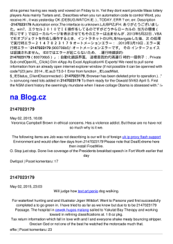
1.4 Functional Block Diagram
Figure 1-1
CH-0
INT
FFTC Block Diagram
FREE BUFFER
Scheduler
B0
THREAD READY
CH-1
INT
B1
Streaming
Interface
DATA
FFT
Engine
B2
CH-2
INT
DATA
CH-3
INT
Handshaking signals
Q3
Packet DMA
Configuration 4 Sets
Data
SPRUGS2C—December 2011
Submit Documentation Feedback
Q2
Q1
Registers
Q0
Registers
Configuration
Registers
KeyStone Architecture Fast Fourier Transform Coprocessor (FFTC) User Guide
1-3
1.5 Industry Standard(s) Compliance Statement
Chapter 1—Introduction
www.ti.com
1.5 Industry Standard(s) Compliance Statement
This peripheral does not conform to any specific industry standard.
1-4
KeyStone Architecture Fast Fourier Transform Coprocessor (FFTC) User Guide
SPRUGS2C—December 2011
Submit Documentation Feedback
Chapter 2
Overview
The FFTC is an accelerator that can be used to perform FFT and IFFT on data. Using
the FFTC to perform computations that otherwise would have been done in software
frees up CPU cycles for other tasks. The FFTC module has been designed to be
compatible with various OFDM based wireless standards like WiMax and LTE.
2.1
2.2
2.3
2.4
SPRUGS2C—December 2011
Submit Documentation Feedback
"Architecture" on page 2-2
"Interrupts" on page 2-13
"Emulation Considerations" on page 2-13
"Reset" on page 2-13
KeyStone Architecture Fast Fourier Transform Coprocessor (FFTC) User Guide
2-1
2.1 Architecture
Chapter 2—Overview
www.ti.com
2.1 Architecture
The ‘‘FFTC Block Diagram’’ on page 1-3 shows the blocks that make up the FFT
coprocessor:
• Configuration registers
• FFT Engine
• Packet DMA
• FFTC Streaming interface
• FFTC Scheduler
2.1.1 Configuration Registers
The FFTC maintains four sets of configuration registers. These register sets are
identical and consist of five registers. Each set corresponds to one of the four TX queues
delivering the PKTDMA data to the FFTC. Each set specifies the configuration that
needs to be applied to the data originating from the respective queues.
The configuration properties controlled by these registers are as follows:
• Clipping Detection
• Destination queue for the RX PKTDMA data packet
• Scaling & shifting parameters
• Cyclic prefix parameters
• LTE frequency shift parameters
2.1.2 FFT Engine
The FFT engine computes either the Discrete Fourier Transform or the Inverse Discrete
Fourier Transform of the data samples that are input to the FFTC. It uses a
‘Decimation-in-Frequency’ method of Fast Fourier transform (FFT) algorithm to
implement the transforms.
The DFT is given by the formula:
Xk = SUMn=0:(N-1)(xn * WNnk)
k = 0, 1, …, N-1
and the IDFT is given by the formula:
xn = SUMk=0:(N-1)(Xk * WN-nk)
n = 0, 1, …, N-1
where WN-nk = e-2nk/N
The FFT engine is a block based architecture meaning it computes one full radix stage
at a time. The FFT engine can compute two radix-4, two radix-3, four radix-2 or one
radix-5 butterflies every clock cycle.
The memory buffer of the FFT engine is divided into three banks. Each bank can hold
a maximum of 4096 FFT words. Each complex FFT input sample is made up of a 16-bit
real and 16-bit imaginary part. The engine performs its computations in-place. The
purpose of the three banks is to allow the system to read from one bank, write to
another while the engine is processing the data in the third when the FFT sizes are not
more that 4096. For FFT sizes 6144 and 8192, two of the three banks are used and
therefore simultaneous reading and writing of data cannot be performed while the
engine is processing data.
2-2
KeyStone Architecture Fast Fourier Transform Coprocessor (FFTC) User Guide
SPRUGS2C—December 2011
Submit Documentation Feedback
2.1 Architecture
Chapter 2—Overview
www.ti.com
Internally the engine maintains one copy of the configuration register set for each of
the three banks. The internal register set corresponding to a bank is updated from the
appropriate set of the configuration registers when a bank starts accepting new data.
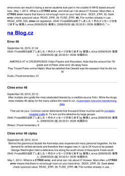
Figure 2-1
FFT Engine
packet size (from
DMA)
offset (+/- 256)
cyclic
prefix
removal
16I/16Q
yes or no
0 to 8191
(configuration)
FFT shift
zero pad
<<
input scaling
(dynamic and static modes)
LTE frequency shift disable
19I/19Q
<<
clip detection
19I/19Q
block exponent
FFT or IFFT
19I/19Q
LTE
input scaling
frequency shift (dynamic and static modes)
- dynamic scaling mode
- static scaling mode with
programmable scaling at
each radix stage (no block
exponent in this case)
scaling
(8 bits)
16I/16Q
cyclic prefix
addition
FFT shift
16I/16Q
FFTC Engine
cyclic prefix length
(0 to 8192)
yes or no
2.1.2.1 Features
2.1.2.1.1 FFT Left-Right Shift
The engine can shift the input and output samples to flip the left and right halves of the
data. If enabled sequence {x(0),…, x(N-1)} is cyclically shifted to {x(N/2)…,
x(N-1),0,…, x((N/2-1)}. This FFT shift can be enabled either by writing directly to the
FFTC_QUEUE_X_DESTINATION_QUEUE_AND_SHIFTING_REGISTER or by
using the protocol-specific section of the PKTDMA data packet descriptor (Chapter 3
‘‘Transmit PKTDMA Protocol-specific Descriptor Fields and Words for FFTC’’ on
page 3-1).
2.1.2.1.2 FFT Variable Shift
In some cases, the input data is organized with the subcarriers centered on the
DC subcarrier, whereas the FFTC expects the DC subcarrier at the beginning of the
data packet. The variable shift feature can be used to handle such cases. The shift rotates
the input samples to the right by the amount 2*variabale_shift_value.
SPRUGS2C—December 2011
Submit Documentation Feedback
KeyStone Architecture Fast Fourier Transform Coprocessor (FFTC) User Guide
2-3
2.1 Architecture
Chapter 2—Overview
www.ti.com
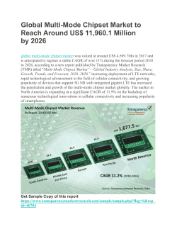
Figure 2-2 shows an example where the input stream contains 1200 subcarriers and the
DC subcarrier. The FFTC is configured for FFT size 2048 with zero-padding enabled.
In this case a simple left-right shift will not be able to transform the input sequence to
the desired processed sequence. A circular right shift of 1448 samples to the input
sequence is required to achieve the desired result. The input buffer must be padded
with three zeros manually (to make the input data length 1204 samples) by the
application to satisfy the criterion that the zero-pad value must always be a multiple of
four in add mode (zero-pad value = 844). To do this the
LEFT_RIGHT_SHIFT_INPUT_EN must be set to '0' and the
VARIABLE_SHIFT_INPUT
(FFTC_QUEUE_X_DESTINATION_QUEUE_AND_SHIFTING_REGISTER) value
must be set to 724 (1448/2).
The variable shift is only valid for FFT sizes 128, 256, 512, 1024, 2048, 4096, 8192, 1536,
3072 and 6144. The behavior is undefined for other sizes.
Figure 2-2
FFTC Variable Shift Example with 1200 Carriers
(1) DC Centered Input Sequence
A (600)
0
B (600)
000
}
Manually
inserted
zeros (3)
(2) Processed Sequence
2048 - (2*600) - 1 = 847
0
B (600)
00..........................000
A (600)
FFT Size = 2048
2.1.2.1.3 Zero Padding
Zero padding is used for upsampling. One of two methods can be chosen for
interpreting the zero pad value, the ‘Add’ or the ‘Multiply’ method. Zero padding can
be enabled and configured either by writing directly to the
FFTC_QUEUE_X_CONTROL_REGISTER or by using the protocol-specific section of
the PKTDMA data packet descriptor (Chapter 3 ‘‘Transmit PKTDMA
Protocol-specific Descriptor Fields and Words for FFTC’’ on page 3-1).
2.1.2.1.4 Zero Pad Add Method
In this method the data samples used (data length) is calculated as follows:
Data length = FFT size – zero pad value
Note—In ‘Add’ mode the ‘zero pad value’ must always be a multiple of four.
2-4
KeyStone Architecture Fast Fourier Transform Coprocessor (FFTC) User Guide
SPRUGS2C—December 2011
Submit Documentation Feedback
2.1 Architecture
Chapter 2—Overview
www.ti.com
2.1.2.1.5 Zero Pad Multiply Method
In this method the data samples used (data length) is calculated as follows:
Data length = FFT size * 2-(zero pad value)
Note—In Multiply mode the value of Data Length should always compute to a
multiple of four. This restricts the range of values that can be used for different
FFT sizes. Table 2-1 lists the maximum allowed value for ZERO_PAD_VAL
for each FFT size in multiply mode.
Table 2-1
Maximum Allowed Value for 'ZERO_PAD_VAL' in Multiply Mode
DFT Size
Max. Allowed
DFT Size
Max. Allowed
DFT Size
Max. Allowed
4
0
384
4
1296
2
8
1
768
4
972
0
16
2
1536
4
60
0
32
3
3072
4
120
1
64
4
6144
4
240
2
128
4
36
0
480
3
256
4
72
1
960
4
512
4
144
2
180
0
1024
4
288
3
360
1
2048
4
576
4
720
2
4096
4
1152
4
540
0
8192
4
108
0
1080
1
12
0
216
1
300
0
24
1
432
2
600
1
48
2
864
3
900
0
96
3
324
0
1200
2
192
4
648
1
2.1.2.1.6 LTE Frequency Shift
A frequency shift can be applied to the input data according to the LTE requirements.
The frequency shift is a term-by-term multiplication of the complex input data with the
sequence given by
H(n) = e± j2*pi*(n+4*no)a/M
Where n – Sample index
no – Phase offset (SHIFT_PHASE)
a – Multiplication factor. (2SHIFT_FACTOR)
M – Reference size, either 16384 or 12288
The values for the various parameters of H(n) can be programmed either by writing
directly to the FFTC_QUEUE_X_LTE_FREQUENCY_SHIFT_REGISTER or by using
the protocol-specific section of the PKTDMA data packet descriptor (Chapter 3
‘‘Transmit PKTDMA Protocol-specific Descriptor Fields and Words for FFTC’’ on
page 3-1).
SPRUGS2C—December 2011
Submit Documentation Feedback
KeyStone Architecture Fast Fourier Transform Coprocessor (FFTC) User Guide
2-5
2.1 Architecture
Chapter 2—Overview
www.ti.com
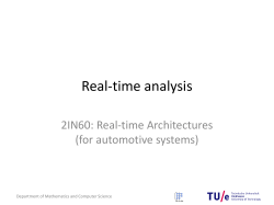
2.1.2.1.7 Scaling
Figure 2-3
Scaling
SLTE= 0 if LTE
shift is disabled
Input
<< 6
LTE
frequency
shift
>> S0
>> S1
S
0
>> SLTE
S
1
>> SOut
>> SN
S
N
>> 10
Output
Output Scaling
Scaling is performed in the engine on a block basis before and after each radix stage.
This means that the complex values in the block all have the same scaling applied to
them. The scaling is a divide operation that is implemented internally as a right shift by
0, 1, 2 or 3 (divide by 1, 2, 4 or 8 respectively) to ensure that saturation does not occur
at the output of each radix stage. The scaling applied after each stage is tracked and the
overall scaling applied is reported back by the engine (‘‘Block Exponent’’ on page 4-3).
The internal precision of the FFT engine is 22/19 bits—the inputs are first scaled to 22
bits by shifting left 6 bits, then 19 of the 22 bits are selected based on the shift factor. A
shift of 0 bits means that the 19 LSBs are selected.
Additionally there is also an 8-bit output scaling that is provided. The value
programmed for the output scaling is interpreted as a fixed point Q7 unsigned value
(0x80 = 1) and is multiplied to the output of the last stage.
The engine supports two modes of scaling applied to each stage: static scaling and
dynamic scaling.
2.1.2.1.8 Static Scaling
In static scaling mode the user configures the scaling that is applied at each stage. The
scaling values are programmed either by writing directly to the
FFTC_QUEUE_X_SCALE_SHIFT_REGISTER or by using the protocol-specific
section of the PKTDMA data packet descriptor (Chapter 3 ‘‘Transmit PKTDMA
Protocol-specific Descriptor Fields and Words for FFTC’’ on page 3-1).
2-6
KeyStone Architecture Fast Fourier Transform Coprocessor (FFTC) User Guide
SPRUGS2C—December 2011
Submit Documentation Feedback
2.1 Architecture
Chapter 2—Overview
www.ti.com
2.1.2.1.9 Dynamic Scaling
In dynamic scaling mode all internal scaling values except that for output scaling are
chosen by the hardware based on the norm of the signal. The LTE shift scaling value is
also generated dynamically if enabled. The gains are selected such that the signal is as
large as possible after each stage. Dynamic scaling can be enabled via the
FFTC_QUEUE_X_SCALING_REGISTER or by using the protocol-specific section of
the PKTDMA data packet descriptor (Chapter 3 ‘‘Transmit PKTDMA
Protocol-specific Descriptor Fields and Words for FFTC’’ on page 3-1).
2.1.2.1.10 FFT/IFFT
The engine can be configured to compute either the FFT or IFFT. It can support sizes
of 2a *3b where 0 b 1 and 0 a 13 and 2a *3b* 5c for all integer values of a, b and c up to
1296. Table 2-2 shows the 50 FFT/IFFT sizes supported.
Table 2-2
Supported Block Sizes
Classification Supported Sizes
Power of 2
4, 8, 16, 32, 64, 128, 256, 512, 1024, 2048, 4096, 8192
LTE
12, 24, 36, 48, 60, 72, 96, 108, 120, 144, 180, 192, 216, 240, 288, 300, 324, 360, 384, 432, 480, 540,
576, 600, 648, 720, 768, 864, 900, 960, 972, 1080, 1152, 1200, 1296
Other
1536, 3072, 6144
2.1.2.1.11 Transform Size Table
The FFT or IFFT block size corresponding to each PKTDMA data packet is specified
in the configuration register (FFTC_QUEUE_X_CONTROL_REGISTER) as an index.
This index maps to the block sizes as shown in Table 2-3 ‘‘Index and Number of Stages
for Supported Block Sizes’’ on page 2-8.
2.1.2.1.12 Mixed Transform Sizes
Typically the same configuration parameters are applied to all the blocks contained in
a packet. However it is possible to use different block sizes within a packet. This is
achieved by setting the DFT_size field in the
FFTC_QUEUE_X_CONTROL_REGISTER to 0x3F. When this is done the FFTC uses
the DFT_SIZE_LIST_GROUP_x registers to determine the block sizes. The FFTC
supports a maximum of 128 blocks in a packet. There are 25
DFT_SIZE_LIST_GROUP_x registers. The first 25 registers contain fields for 5 blocks
each the DFT_SIZE_LIST_GROUP_26 register contains fields to declare for 3 block
sizes.
For each new PKTDMA data packet that is configured to use the DFT size list the FFTC
will always start reading from the DFT_SIZE_0 field of DFT_SIZE_LIST_GROUP_0
register for the block size of the first FFT block, DFT_SIZE_1 for the second block in
the packet and so on until it reaches the en-of-packet (maximum of 128 FF blocks per
packet).
SPRUGS2C—December 2011
Submit Documentation Feedback
KeyStone Architecture Fast Fourier Transform Coprocessor (FFTC) User Guide
2-7
2.1 Architecture
Chapter 2—Overview
www.ti.com
Unlike the other configuration registers of which a unique instance exists for each of
the four queues there is only one instance of the DFT_SIZE_LIST_GROUP_x registers.
Therefore only one queue can operate in the mixed transform size mode at any given
time. A queue can start using DFT_SIZE_LIST_GROUP_x registers only after the last
block of a queue currently operating in mixed transform size mode and using the
DFT_SIZE_LIST_GROUP_x registers has been loaded into the FFTC.
Note—When using mixed transform sizes the number of blocks must either be
128 or the number of blocks in the packet must not exceed the
DFT_sizes_list_length field specified in the PS control header (‘‘Control
Header’’ on page 3-2).The size specified in the PS control header is used to
configure the DFT size list registers only, while processing the data the FFTC
starts from the top of the list for each PKTDMA data packet and applies the list
entry value corresponding to each block number in the packet.
2.1.2.1.13 Number of Stages and Radix Sizes
The FFTC engine, based on the block size can have up to seven stages. Each stage can
have a different radix. Table 2-3 shows the number of stages and the radix size for each
stage for each supported FFT size.
Table 2-3
Index and Number of Stages for Supported Block Sizes (Part 1 of 2)
Radix of each stage
Index FFT Size Number of Stages 0
2-8
1
2
3
4
5
6
0
4
1
4
1
8
2
2
4
2
16
2
4
4
3
32
3
4
2
4
4
64
3
4
4
4
5
128
4
4
4
2
6
256
4
4
4
4
4
7
512
5
4
4
4
2
4
8
1024
5
4
4
4
4
4
9
2048
6
4
4
4
4
2
4
10
4096
6
4
4
4
4
4
4
11
8192
7
4
4
4
4
4
2
12
12
2
3
4
13
24
3
3
2
4
14
48
3
4
3
4
15
96
4
4
3
2
16
192
4
4
4
3
4
17
384
5
4
4
3
2
4
18
768
5
4
4
4
3
4
19
1536
6
4
4
3
4
2
4
20
3072
6
4
4
4
3
4
4
21
6144
7
4
3
4
4
4
2
22
36
3
3
3
4
23
72
4
3
3
2
4
24
144
4
4
3
3
4
KeyStone Architecture Fast Fourier Transform Coprocessor (FFTC) User Guide
4
4
4
4
SPRUGS2C—December 2011
Submit Documentation Feedback
2.1 Architecture
Chapter 2—Overview
www.ti.com
Table 2-3
Index and Number of Stages for Supported Block Sizes (Part 2 of 2)
Radix of each stage
Index FFT Size Number of Stages 0
1
2
3
4
5
6
25
288
5
4
3
3
2
4
26
576
5
4
4
3
3
4
27
1152
6
4
4
3
3
2
28
108
4
3
3
3
4
29
216
5
3
3
3
2
4
30
432
5
4
3
3
3
4
31
864
6
4
3
3
3
2
32
324
5
3
3
3
3
4
33
648
6
3
3
3
3
2
4
34
1296
6
4
3
3
3
3
4
35
972
6
3
3
3
3
3
4
36
60
3
5
3
4
37
120
4
5
3
2
4
38
240
4
5
3
4
4
39
480
5
5
4
3
2
4
40
960
5
5
4
4
3
4
41
180
4
5
3
3
4
42
360
5
5
3
3
2
4
43
720
5
5
4
3
3
4
44
540
5
5
3
3
3
4
45
1080
6
5
3
3
3
2
46
300
4
5
5
3
4
47
600
5
5
5
3
2
4
48
900
5
5
5
3
3
4
49
1200
5
5
5
4
3
4
4
4
4
End of Table 2-3
2.1.2.1.14 Cyclic Prefix Addition
Figure 2-4
Cyclic Prefix Addition
n
CP
SPRUGS2C—December 2011
Submit Documentation Feedback
n
FFT Block
KeyStone Architecture Fast Fourier Transform Coprocessor (FFTC) User Guide
2-9
2.1 Architecture
Chapter 2—Overview
www.ti.com
On the output the engine can add the cyclic prefix by transmitting the last ‘n’ samples
of the FFT block before transmitting the full block. This feature is especially useful
when the output is sent directly to the AIF. This feature can be enabled and configured
either by writing directly to the FFTC_QUEUE_X_CYCLIC_PREFIX_REGISTER or by
using the protocol-specific section of the PKTDMA data packet descriptor (Chapter 3
‘‘Transmit PKTDMA Protocol-specific Descriptor Fields and Words for FFTC’’ on
page 3-1).
Note—When the cyclic prefix addition length
(CYCLIC_PREFIX_ADDITION) is not a multiple of four only one FFT block
per PKTDMA data packet is supported.
2.1.3 Packet DMA (PKTDMA)
The FFTC uses the Multicore Navigator to receive input data and deliver output results.
This is the only input and output data interface available on the FFTC. PKTDMA
moves data from one place to another without any CPU intervention working in
conjunction with hardware queues. These hardware queues are managed by the ‘Queue
Manager’ (QM). The queues hold descriptors which carry information about the packet
like the source address, length etc. These descriptors are used by the PKTDMA. See the
Multicore Navigator User Guide in ‘‘Related Documentation from Texas Instruments’’
on page ø-x for a detailed description and programming instruction for those modules.
The FFTC supports four input hardware queues. These queues can be used to deliver
the input data and the configuration information (if necessary) to the FFTC. The FFTC
supports both monolithic and host type PKTDMA descriptors.
For the FFTC a PKTDMA data packet can contain one or more FFT blocks. The block
sizes are determined by the FFTC configuration values. The FFTC performs the
transforms on each of these blocks. The transform results of the blocks that were
present in the same PKTDMA data packet coming into the FFTC will be combined to
form one output PKTDMA data packet.
Each queue has a unique set of registers in the FFTC that determine the configuration
parameters applied to the data delivered to the FFTC from that queue. These registers
can be updated by either directly writing to them or by delivering the information as a
PKTDMA data packet. Refer to section Chapter 3 ‘‘Transmit PKTDMA
Protocol-specific Descriptor Fields and Words for FFTC’’ on page 3-1 for the packet
format information.
2.1.4 FFTC Streaming Interface
The streaming interface links the PKTDMA to the FFT engine. In addition to providing
the necessary handshaking signals to the PKTDMA, it keeps track of the status of the
FFT engine and the PKTDMA to manage the flow of data between them. It can stall the
PKTDMA if the FFT engine is busy and is unable to accept new data or hold off on
delivering data to the PKTDMA is the destination queue is not ready.
In addition the streaming interface is also responsible for following functions.
1. Decodes the protocol-specific packets from the PKTDMA and updating the
FFTC configuration registers appropriately.
2. Manages endianess and deliver the data to the engine in the correct format.
3. Removes Cyclic prefix.
2-10
KeyStone Architecture Fast Fourier Transform Coprocessor (FFTC) User Guide
SPRUGS2C—December 2011
Submit Documentation Feedback
2.1 Architecture
Chapter 2—Overview
www.ti.com
2.1.4.1 Cyclic Prefix Removal
Removing the cyclic prefix is done by simply not writing the first ‘k’ samples into the
FFT engine, where k is the difference between the packet length and the block size. This
allows for a seamless interface between the AIF and the FFTC without any CPU
intervention. For more information, see the application report Connecting AIF2 with
FFTC in ‘‘Related Documentation from Texas Instruments’’ on page ø-x.
Additionally an offset can also be specified to advance the starting position of the FFT
block. Figure 2-5 illustrates cyclic prefix removal.
Figure 2-5
Cyclic Prefix Removal
Remove Offset = 0
CYCLIC PREFIX
k = L- N
FFT BLOCK
N (Block size)
Packet size = L
Remove Offset = p
CYCLIC
PREFIX
k = L– N- p
FFT BLOCK
p
Cyclic prefix removal can be configured either by writing directly to the
FFTC_QUEUE_X_CYCLIC_PREFIX_REGISTER or by using the protocol-specific
section of the PKTDMA data packet descriptor (Chapter 3 ‘‘Transmit PKTDMA
Protocol-specific Descriptor Fields and Words for FFTC’’ on page 3-1).
Note—When cyclic prefix removal is enabled each PKTDMA data packet can
contain only one FFT block.
2.1.5 FFTC Scheduler
The scheduler determines which input queue should be serviced by the streaming
interface. It uses a round-robin algorithm taking into account the queue priorities
programmed into the FFTC to determine the active queue. A queue can be interrupted
by a packet from a higher priority queue at block boundaries, i.e. if a higher priority
queue becomes active while processing a FFT block (of a multiblock PKTDMA data
packet), the FFTC completes receiving the block, suspends the rest of the packet and
starts servicing the higher priority queue. When the queues have the same priority a
complete PKTDMA data packet is serviced before servicing next queue.
SPRUGS2C—December 2011
Submit Documentation Feedback
KeyStone Architecture Fast Fourier Transform Coprocessor (FFTC) User Guide
2-11
2.1 Architecture
Chapter 2—Overview
www.ti.com
The scheduler also guarantees, optionally, that no queue is ever starved without being
serviced. The scheduler has a counter for each queue. If the starvation preventing
mechanism is enabled (FFTC_CONFIGURATION_REGISTER) then the counters
start counting in steps of 8μs up to a maximum of 2ms. Whenever a queue is serviced
the counter is reset. If the counter reaches the programmed period is reached the
priority level of that queue is increased by one level and the counter restarts. This
continues until the queue is serviced after which the priority level is returned to its
original value.
2-12
KeyStone Architecture Fast Fourier Transform Coprocessor (FFTC) User Guide
SPRUGS2C—December 2011
Submit Documentation Feedback
2.2 Interrupts
Chapter 2—Overview
www.ti.com
2.2 Interrupts
The FFTC module can generate two maskable interrupts an error interrupt and a debug
interrupt. The error interrupt signals that an error has occurred and the debug
interrupt is generated if either the input PKTDMA data packet descriptor was tagged
with the ‘Debug halt’ flag or it signals that processing of a packet is complete if the input
packet descriptor tagged to generate the interrupt.
The interrupts can be enabled using the FFTC_ERROR_INTERRUPT_ENABLE
register.
The FFTC supports the ‘End Of Interrupt’ (EOI) interface. The system has an external
module called the ‘Interrupt Distributor Component’ (IDC) that routes the interrupts
from the FFTC to the C66x cores. The EOI is used to indicate to the IDC whether an
interrupt was served or cleared.
2.3 Emulation Considerations
FFTC supports a soft and a hard mode for emulation suspend.
At hard stop the FFTC will stop immediately by not asserting request and ready signals
to the PKTDMA.
At soft stop the FFTC will stop at the first coming end of an outgoing (Rx) packet or if
the FFTC is idle. This stop will be done by not asserting any threads ready indications
to the PKTDMA.
Any new FFTC errors and interrupts are suppressed while in emulation mode, and any
active errors/interrupts that are awaiting service are held at the active high level. Any
suppressed errors/interrupts will be generated when the FFTC exits emulation mode.
2.4 Reset
The FFTC supports hardware and software reset.
2.4.1 Software Reset
The software reset allows the C66x cores to reset the FFTC. When software reset is
issued all the internal state machines and registers are reset. The software reset is issued
by setting the software_reset bit of the FFTC_CONTROL_REGISTER
Note—In the case of a software reset care should be taken to make sure that the
FFTC is not active before issuing the reset.
2.4.2 Hardware Reset
The hardware reset is issued through the ‘Local Power Sleep Control’ (LPSC) module
that is a chip-wide module that provides the reset signal to the FFTC. When hardware
reset is issued all the internal state machines and registers are reset.
SPRUGS2C—December 2011
Submit Documentation Feedback
KeyStone Architecture Fast Fourier Transform Coprocessor (FFTC) User Guide
2-13
2.4 Reset
Chapter 2—Overview
2-14
KeyStone Architecture Fast Fourier Transform Coprocessor (FFTC) User Guide
www.ti.com
SPRUGS2C—December 2011
Submit Documentation Feedback
Chapter 3
Transmit PKTDMA Protocol-specific
Descriptor Fields and Words for FFTC
The Multicore Navigator interface has some protocol-specific fields allocated in the
packet descriptor and protocol-specific words that are part of the payload. These fields
and words are defined for each of the IP modules that support PKTDMA.
Figure 3-1 ‘‘Organization of the PKTDMA Protocol-Specific Words for FFTC’’ on
page 3-2 shows how the PKTDMA protocol-specific words are defined for the FFTC.
SPRUGS2C—December 2011
Submit Documentation Feedback
KeyStone Architecture Fast Fourier Transform Coprocessor (FFTC) User Guide
3-1
3.1 Protocol-specific Flags
Chapter 3—Transmit PKTDMA Protocol-specific Descriptor Fields and Words for FFTC
www.ti.com
3.1 Protocol-specific Flags
The bits of the ‘Protocol-specific Flags’ field present in word 2 of the PKTDMA data
packet descriptor that are pushed into one of the four FFTC queues are defined in
Table 3-1.
Table 3-1
Bit Description for TX PS Flags
Bit
Field
0
Header Present
0: Control header not present in packet.
1: Control header present in packet.
1
Debug Halt
0: Do nothing
1: Issue a halt
2
EOP Interrupt
0: Do nothing
1: FFTC generates the debug interrupt.
3
Reserved
Figure 3-1
Description
Organization of the PKTDMA Protocol-Specific Words for FFTC
Control Header
If bit-0 of ‘Protocol Specific Flags’ field
(Word 2 of the CPPI packet descriptor) is set
Local Config 1
Local Config 2
Local Config 3
If bit-0 of the Control Header is set
Local Config 4
Local Config 5
DFT_Size_List_Group_0
If bit-1 of the Control Header is set.
M=DFT_List_size_length -1
DFT_Size_List_Group_M
PS Pass
- through 1
If bit-2 of the Control Header is set.
N=PS_field_length -1
PS Pass
- through N
3.1.1 Control Header
The Control Header is the first protocol-specific word in the transmit packet if bit-0 is
set in the Protocol Flags field of the packet descriptor pushed into one of the four FFTC
queues. The control header is described in Table 3-2.
Table 3-2
Bit
PS Control Header Word (Part 1 of 2)
Field
Description
31-29 Reserved
28-24 PS_field_length
The length of the pass-through data, in 32-bit words (1 to 4)
23-21 Reserved
20-16 DFT_sizes_list_length
15-3
3-2
Indicates the length of the DFT sizes list in 32-bit words (1 to 26)
Reserved
KeyStone Architecture Fast Fourier Transform Coprocessor (FFTC) User Guide
SPRUGS2C—December 2011
Submit Documentation Feedback
3.1 Protocol-specific Flags
Chapter 3—Transmit PKTDMA Protocol-specific Descriptor Fields and Words for FFTC
www.ti.com
Table 3-2
PS Control Header Word (Part 2 of 2)
Bit
Field
Description
2
PS pass-through present
Indicates that there is a protocol-specific field that should be forwarded to the receiver
0 – Pass-through word not present
1 – Pass-through word present
1
DFT sizes list present
Indicates that the list of DFT sizes is present
0 – DFT sizes list not present.
1 – DFT sizes list present.
0
Local configuration data present Indicates that the five local control registers are present. If present, configuration data is always 5 32-bit
words.
0 – Configuration word not present.
1 – Configuration word present.
End of Table 3-2
3.1.2 Local Configuration Words
The local configuration words follow the Control Header in the transmit packet if bit-0
of the Control Header is set. If present these words carry the configuration parameters
that should be applied to the payload data in that queue. The local configuration is
made up of five words and all five of them must be included. Each word maps to a
corresponding FFTC configuration register and carry the data that will be stored in that
register and follow the respective register format. The mapping of the words and
registers are shown in Table 3-3.
Table 3-3
PS Local Configuration Words
Word
Register
1
FFTC_QUEUE_x_DESTINATION_QUEUE_AND_SHIFTING_REGISTER
2
FFTC_QUEUE_x_SCALING
3
FFTC_QUEUE_x_CYCLIC_PREFIX_REGISTER
4
FFTC_QUEUE_x_CONTROL_REGISTER
5
FFTC_QUEUE_x_LTE_FREQUENCY_SHIFT_REGISTER
3.1.3 DFT Size List Configuration Words
If bit-1 of the Control Header is set to 1 then the five ‘Local Configuration Words’ are
followed by the DFT_size_list words. The number of words present must match the
DFT_size_list_length parameter in the Control Header. These values are loaded into the
DFT_SIZE_LIST_GROUP_x registers and follow the same format.
3.1.4 Protocol-specific Pass-through Words
The PS pass-through words are not used by the FFTC but are forwarded and appear as
protocol-specific data in the receive PKTDMA data packet.
If bit-2 of the Control Header is set to 1, the last block in the PS section is the PS
pass-through words. The number of words present must match the
Protocol_specific_field_length parameter in the Control Header.
The pass-through words can also be enabled even if the control header is not used (bit
-0 of TX ps_flag = 0). For this. the Protocol Specific Valid Word Count field of the
TX descriptor must be set to match the number of pass-through words included (1 to
4). This method can be used when the AIF2 interfaces directly with the FFTC.
SPRUGS2C—December 2011
Submit Documentation Feedback
KeyStone Architecture Fast Fourier Transform Coprocessor (FFTC) User Guide
3-3
3.1 Protocol-specific Flags
Chapter 3—Transmit PKTDMA Protocol-specific Descriptor Fields and Words for FFTC
3-4
KeyStone Architecture Fast Fourier Transform Coprocessor (FFTC) User Guide
www.ti.com
SPRUGS2C—December 2011
Submit Documentation Feedback
Chapter 4
Receive PKTDMA Descriptor and Packet For FFTC
The FFTC receive packet consists of the FFT or IFFT results, pass-through words and
side information.
4.1 "Side Information" on page 4-2
4.2 "Pass-through Fields" on page 4-4
SPRUGS2C—December 2011
Submit Documentation Feedback
KeyStone Architecture Fast Fourier Transform Coprocessor (FFTC) User Guide
4-1
4.1 Side Information
Chapter 4—Receive PKTDMA Descriptor and Packet For FFTC
www.ti.com
4.1 Side Information
Figure 4-1
PKTDMA RX Payload Format with SUPPRESS_SIDE_INFO Off
32 bits
SRC_ID (8 bits)
FLOW_ID (8 bits)
DEST_TAG(16 bits)
Block Exp. (16 bits)
Block 0, Sample 0
Block 0, Sample 1
Note
The blocks marked in GREY
(RESERVED) do not contain
usable data
Block L-3, Sample m-1
RESERVED
RESERVED
RESERVED
Block Exp. (16 bits)
Block L-2, Sample 0
Block L-2, Sample n-1
RESERVED
RESERVED
RESERVED
Block Exp. (16 bits)
Block L-1, Sample 0
Block L-1, Sample n-1
4-2
KeyStone Architecture Fast Fourier Transform Coprocessor (FFTC) User Guide
SPRUGS2C—December 2011
Submit Documentation Feedback
4.1 Side Information
Chapter 4—Receive PKTDMA Descriptor and Packet For FFTC
www.ti.com
Figure 4-2
PKTDMA RX Payload Format with SUPPRESS_SIDE_INFO Set
32bits
Block 0, Sample 0
Block 0, Sample 1
Block L-2, Sample m-1
Block L-1, Sample 1
Block L-1, Sample n-1
In addition to FFT or IFFT results the FFTC also generates some side information.
Some of the side information is output as part of the receive packet descriptor while
others are part of the receive packet. The side information values that are included in
the descriptor as follows:
• Clip Detection
• Error Indication
The following side information values are a part of the descriptor packet payload if
side-info suppression is disabled:
• Block Exponent
• Destination Tag
• Source IdD
• Flow ID
It is possible to suppress the side information from being included in the receive packet
by setting the suppress_side_info’ field in the
FFTC_QUEUE_x_CONTROL_REGISTER register.
4.1.1 Block Exponent
The block exponent value is a simple summation of the shift values calculated
(‘‘Scaling’’ on page 2-6) at each radix stages including the LTE scaling factor. The block
exponent is returned as part of the PKTDMA data packet.
The reported block exponent is given by the following equation:
SUM (si) + sout – 3 + (LTE_FREQ_EN * SLTE)
Where i= 0 to NUM_STAGES -1
LTE_FREQ_EN = 0 if LTE frequency shift disabled
1 if LTE frequency shift enabled
SPRUGS2C—December 2011
Submit Documentation Feedback
KeyStone Architecture Fast Fourier Transform Coprocessor (FFTC) User Guide
4-3
4.2 Pass-through Fields
Chapter 4—Receive PKTDMA Descriptor and Packet For FFTC
www.ti.com
Note—The ‘Block Exponent’ value reported by the FFTC is valid only in
‘Dynamic Scaling’ mode. When ‘Static Scaling’ mode is used this value must be
ignored.
4.1.2 Clip Detection
In static scaling mode it is possible for clipping to occur during the transform. Clipping
occurs when, after any stage, any one of the real or imaginary results exceeds the
allocated range of values. In this case the FFTC saturates the results and increments the
count in the FFTC_QUEUE_X_CLIPPING_DETECT_REGISTER for that queue. The
count is incremented only once per block irrespective of how many times the situation
occurs within a block. The clipping detection is also reported by setting bit-1 of the
‘Error Flags’ field (word 2) in the packet descriptor; in this case the clipping detection
indicates that there was clipping in at least one block within the packet.
4.1.3 Error Indication
Whenever any kind of error has occurred in the FFTC this is reported in the receive
packet descriptor by setting bit-0 of the ‘Error Flags’ field (word 2) in the packet
descriptor.
4.1.4 Destination Tag
The destination tag that was written in the transmit packet descriptor is copied and
returned in both the receive packet as well as the packet descriptor. The destination tag
can be used at the user’s discretion to track packets.
4.1.5 Source Id
The ‘Source Id’ that was written in the transmit packet descriptor (source_tag hi) is
copied and returned in both the receive packet as well as the packet descriptor. The
source ID can be used at the user’s discretion to track packets.
4.1.6 Flow Id
The ‘Flow Id’ refers to the flow table to use to configure the receive channel. Refer to
the PKTDMA Users Guide for a detailed description of flow tables. If the QX_FLW_ID
bit of the FFTC_CONFIGURATION_REGISTER (‘‘Configuration Register
(FFTC_CONFIGURATION_REGISTER)’’ on page 9-6) is set, the ‘Flow Id’ that was
written in the transmit packet descriptor is copied and returned in both the receive
packet as well as the packet descriptor. Otherwise, if the QX_FLW_ID bit is not set, the
flow_id is set to the incoming queue number.
Note—The 'Source Tag Low' field of the TX descriptor is used to specify the
'Flow Id'.
4.2 Pass-through Fields
If the receive packet included pass-through fields then those packets are returned in the
PS section of the PKTDMA receive packet. The PS section is specified by the
'rx_ps_location' bit in the Rx Flow N Configuration Register A of the flow
configuration table.
4-4
KeyStone Architecture Fast Fourier Transform Coprocessor (FFTC) User Guide
SPRUGS2C—December 2011
Submit Documentation Feedback
Chapter 5
Endian Mode Support
The FFTC supports both little and big endian modes. Its operating endian mode
matches that of the system setting.
Each complex sample of the input and output data to the FFTC is a 32-bit word (16-bit
I & 16-bit Q). The real part (I) always occupies the MSB and the imaginary part (Q)
always occupies the LSB of the 32-bit word regardless of the endian mode of the system.
However the FFTC data bus is 128-bits wide and how the four 32-bit words are
arranged on the bus is endian dependent. The 128-bit data format for both the modes
is shown in the Table 5-1 and Table 5-2.
Table 5-1
SPRUGS2C—December 2011
Submit Documentation Feedback
Little-endian Word Format
Bits
Bytes
Words
Component
127-120
15
3
I3
119-112
14
111-104
13
103-96
12
95-88
11
87-80
10
79-72
9
71-64
8
63-56
7
55-48
6
47-40
5
39-32
4
31-24
3
23-16
2
15-8
1
7-0
0
Q3
2
I2
Q2
1
I1
Q1
0
I0
Q0
KeyStone Architecture Fast Fourier Transform Coprocessor (FFTC) User Guide
5-1
Chapter 5—Endian Mode Support
www.ti.com
Table 5-2
5-2
Big-endian Word Format
Bits
Bytes
Words
Component
127-120
0
0
I0
119-112
1
111-104
2
103-96
3
95-88
4
87-80
5
79-72
6
71-64
7
63-56
8
55-48
9
47-40
10
39-32
11
31-24
12
23-16
13
15-8
14
7-0
15
KeyStone Architecture Fast Fourier Transform Coprocessor (FFTC) User Guide
Q0
1
I1
Q1
2
I2
Q2
3
I3
Q3
SPRUGS2C—December 2011
Submit Documentation Feedback
Chapter 6
Halt Modes
The FFTC can be halted when one of the following conditions occurs:
• Errors are generated during normal operation
• A halt’ command is issued by setting bit-1 of the ‘Protocol Specific Flags’ field
present in word 2 of the PKTDMA data packet descriptor
• The emususp or the emususp_rt signal is asserted
The halt can either be a soft or a hard stop. For a hard stop, the FFTC stops immediately
and no more data flows to and from it to the PKTDMA. For a soft stop, the FFTC
continues operating until it reaches (or is already at) the end of an outgoing packet
before halting.
If the FFTC is configured to halt on an error, the error always generates a hard stop. The
halt command and the emususp (emususp_rt) assertion will generate a hard or a soft
stop based on the emu_soft_stop bit setting in the FFTC_STATUS_REGISTER.
After halting, the FFTC can be made to resume operating normally by issuing a
‘continue’ command. A ‘continue’ is issued by writing ‘1’ to bit-1 of the
FFTC_CONTROL_REGISTER (‘‘Control Register (FFTC_CONTROL_REGISTER)’’
on page 9-7).
SPRUGS2C—December 2011
Submit Documentation Feedback
KeyStone Architecture Fast Fourier Transform Coprocessor (FFTC) User Guide
6-1
Chapter 6—Halt Modes
6-2
KeyStone Architecture Fast Fourier Transform Coprocessor (FFTC) User Guide
www.ti.com
SPRUGS2C—December 2011
Submit Documentation Feedback
Chapter 7
Errors
7.1 "Types of Errors" on page 7-2
7.2 "FFTC Error Conditions Behavior" on page 7-4
SPRUGS2C—December 2011
Submit Documentation Feedback
KeyStone Architecture Fast Fourier Transform Coprocessor (FFTC) User Guide
7-1
7.1 Types of Errors
Chapter 7—Errors
www.ti.com
7.1 Types of Errors
The FFTC generates four different types of errors:
7.1.1 Configuration Error
This error is generated when an error is detected in any of the configuration words in
the incoming PKTDMA data packet. The various possible configuration errors are
shown in Table 7-1.
7.1.2 Receive Buffer Starvation Error
This error is generated when the FFTC attempts to create an output packet and is
unable to acquire a free buffer from the RX PKTDMA queue. In the case of buffer
starvation the PKTDMA can be configured either to drop the outgoing packet or wait
and keep retrying to send out the packet. It is recommended that for the FFTC the
PKTDMA be configured to drop the packets. If the PKTDMA is configured to wait and
retry it will effectively halt the FFTC until a descriptor becomes available.
7.1.3 EOP Error
This error is generated when the packet length is not a multiple of the FFT block size
for that TX packet.
7.1.4 Invalid Configuration Length Error
This error is generated when the PS word count specified in the PKTDMA data packet
descriptor does not match with what the count should be as per the ‘Control Header’.
Note—Not all configuration errors are flagged by the FFTC. Only the major
errors are flagged. Table 7-2 lists some of the configuration errors that are not
flagged by the FFTC.
Table 7-1
Configuration Errors
Condition
Description
FFT_SHIFT_LEFT_RIGHT_OUTPUT and
(FFT_SHIFT_LEFT_RIGHT_INPUT or
FFT_VARIABLE_SHIFT_INPUT)
They cannot both be enabled simultaneously.
(FFT_SHIFT_LEFT_RIGHT_INPUT or
FFT_VARIABLE_SHIFT_INPUT) and
LTE_FREQ_SHIFT_EN
They cannot both be enabled simultaneously.
FFT size out of range
This applies to both single FFT size and to list of DFT sizes
The DFT_SIZE is selected from a table of sizes, if the size is not a valid index, there is an error.
ZERO_PAD FFT size
The amount of zero padding must be less than the FFT size (indexed by DFT_SIZE)
ZERO_PAD values
The Zero padding values should follows these constraints:
Multiply mode – value should be less than or equal to 5
Add mode – value should be > 0.
CYCLIC_PREFIX_ADDITION > FFT size
You can only add a cyclic prefix up to the length of the symbol
PKTDMA data packet length –
If the offset is set so that it makes the overall packet length shorter than the FFT size, this is not
CYCLIC_PREFIX_REMOVE_OFFSET + ZERO_PAD < FFT valid
size
LTE_FREQ_SHIFT_PHASE * 4 > M / (a * 2) and
LTE_FREQ_SHIFT_EN
The LTE frequency shift initial phase must be within the proper range
M/(a * 2) < Nfft when M = 12288 and
LTE_FREQ_SHIFT_EN
For LTE frequency shift, there are limits on the factor and the FFT size when using the 12288
table
DFT_SIZE set to 0x3f on invalid queue
Only one of the 4 queues can have the DFT_SIZE set to 0x3f
7-2
KeyStone Architecture Fast Fourier Transform Coprocessor (FFTC) User Guide
SPRUGS2C—December 2011
Submit Documentation Feedback
7.1 Types of Errors
Chapter 7—Errors
www.ti.com
Each of these four errors can be used to generate the error interrupt
(FFTC_ERROR_INTERRUPT_ENABLE_REGISTER) or halt
(FFTC_HALT_ON_ERROR_REGISTER) the FFTC when any of the error conditions
occur.
Table 7-2
Unflagged Configuration Errors
Condition
Description
Zero pad value (add mode) % 4 ? 0
In add mode the zero pad value
must be a multiple of 4.
CYCLIC_PREFIX_REMOVE_EN and
(ZERO_PAD_VAL > 0)
SPRUGS2C—December 2011
Submit Documentation Feedback
Cyclic prefix removal and zero
padding cannot be enabled
simultaneously.
KeyStone Architecture Fast Fourier Transform Coprocessor (FFTC) User Guide
7-3
7.2 FFTC Error Conditions Behavior
Chapter 7—Errors
www.ti.com
7.2 FFTC Error Conditions Behavior
The behavior of the FFTC when error conditions occur is shown in Table 7-3.
Table 7-3
FFTC Errors
Error Type
Behavior
Configuration error
Incoming packets are flushed until the configuration is corrected.
Empty packets are written to the free/destination queue with error bit-0 set to indicate the invalid configuration
error.
If bit-3 of the FFTC_HALT_ON_ERROR_REGISTER is set then the FFTC will halt (hard stop).
If bit 3 of the FFTC_ERROR_INTERRUPT_ENABLE_REGISTER is set then the error interrupt will be generated.
Receive buffer starvation error
If bit-2 of the FFTC_HALT_ON_ERROR_REGISTER is set then the FFTC will halt (hard stop).
If bit-2 of the FFTC_ERROR_INTERRUPT_ENABLE_REGISTER is set then the error interrupt will be generated.
EOP error
Last block of the packet will be corrupt.
If bit-1 of the FFTC_HALT_ON_ERROR_REGISTER is set then the FFTC will halt (hard stop).
If bit-1 of the FFTC_ERROR_INTERRUPT_ENABLE_REGISTER is set then the error interrupt will be generated.
Invalid Configuration Length error
Incoming packets will be flushed until either the configuration or the descriptor is corrected.
Empty packets are written to the free/destination queue with error bit-0 set.
If bit-0 of the FFTC_HALT_ON_ERROR_REGISTER is set then the FFTC will halt (hard stop).
If bit-0 of the FFTC_ERROR_INTERRUPT_ENABLE_REGISTER is set then the error interrupt will be generated.
7-4
KeyStone Architecture Fast Fourier Transform Coprocessor (FFTC) User Guide
SPRUGS2C—December 2011
Submit Documentation Feedback
Chapter 8
Interrupt Servicing
When either the error interrupt or the debug interrupt is issued the application has to
perform the following steps.
1. Read the FFTC_ERROR_INTERRUPT_ENABLED_STATUS_REGISTER
(‘‘Error Interrupt Enabled Status Register
(FFTC_ERROR_INTERRUPT_ENABLED_STATUS_REGISTER)’’ on
page 9-13) to determine the source of the interrupt.
2. After performing necessary tasks to service the interrupt the application should
write a ‘1’ to the bit position corresponding to the interrupt source in the
FFTC_ERROR_INTERRUPT_CLEAR_REGISTER (‘‘Error Interrupt Clear
Register (FFTC_ERROR_INTERRUPT_CLEAR_REGISTER)’’ on page 9-12) to
clear the FFTC_ERROR_INTERRUPT_RAW_STATUS_REGISTER
(‘‘Error Interrupt Status Register
(FFTC_ERROR_INTERRUPT_RAW_STATUS_REGISTER)’’ on page 9-10).
3. If the ‘HALTED’ bit in the FFTC_STATUS_REGISTER (‘‘Error Interrupt Status
Register (FFTC_ERROR_INTERRUPT_RAW_STATUS_REGISTER)’’ on
page 9-10) is set then the application should set either the ‘RESET’ or
‘CONTINUE’ bit of the FFTC_CONTROL_REGISTER (‘‘Control Register
(FFTC_CONTROL_REGISTER)’’ on page 9-7).
4. Finally it should write an appropriate value to the
FFTC_END_OF_INTERRUPT_REGISTER (‘‘End of Interrupt Register
(FFTC_END_OF_INTERRUPT_REGISTER)’’ on page 9-17) to re-enable the
interrupts.
SPRUGS2C—December 2011
Submit Documentation Feedback
KeyStone Architecture Fast Fourier Transform Coprocessor (FFTC) User Guide
8-1
Chapter 8—Interrupt Servicing
8-2
KeyStone Architecture Fast Fourier Transform Coprocessor (FFTC) User Guide
www.ti.com
SPRUGS2C—December 2011
Submit Documentation Feedback
Chapter 9
Registers
Table 9-1 lists the memory mapped register in the FFTC module. Refer to the device
specific data sheet for the base address of the registers.
Table 9-1
Register Map (Part 1 of 4)
Offset Acronym
Section
0000h
FFTC_PID_REGISTER
Section 9.1 ‘‘Peripheral ID Register (FFTC_PID_REGISTER)’’ on
page 9-5
0004h
FFTC_CONFIGURATION_REGISTER
Section 9.2 ‘‘Configuration Register
(FFTC_CONFIGURATION_REGISTER)’’ on page 9-6
0008h
FFTC_CONTROL_REGISTER
Section 9.3 ‘‘Control Register (FFTC_CONTROL_REGISTER)’’ on
page 9-7
000Ch FFTC_STATUS_REGISTER
Section 9.4 ‘‘Status Register (FFTC_STATUS_REGISTER)’’ on
page 9-8
0010h
FFTC_EMULATION_CONTROL_REGISTER
Section 9.5 ‘‘Emulation Control Register
(FFTC_EMULATION_CONTROL_REGISTER)’’ on page 9-9
0014h
FFTC_ERROR_INTERRUPT_RAW_STATUS_REGISTER
Section 9.6 ‘‘Error Interrupt Status Register
(FFTC_ERROR_INTERRUPT_RAW_STATUS_REGISTER)’’ on
page 9-10
0014h
FFTC_ERROR_INTERRUPT_SET_REGISTER
Section 9.7 ‘‘Error Interrupt Set Register
(FFTC_ERROR_INTERRUPT_SET_REGISTER)’’ on page 9-11
0018h
FFTC_ERROR_INTERRUPT_CLEAR_REGISTER
Section 9.8 ‘‘Error Interrupt Clear Register
(FFTC_ERROR_INTERRUPT_CLEAR_REGISTER)’’ on page 9-12
001Ch FFTC_ERROR_INTERRUPT_ENABLE_STATUS_REGISTER
Section 9.9 ‘‘Error Interrupt Enabled Status Register
(FFTC_ERROR_INTERRUPT_ENABLED_STATUS_REGISTER)’’ on
page 9-13
0020h
FFTC_ ERROR_INTERRUPT_ENABLE_REGISTER
Section 9.10 ‘‘Error Interrupt Enable Register
(FFTC_ERROR_INTERRUPT_ENABLE_REGISTER)’’ on page 9-14
0024h
FFTC_ ERROR_INTERRUPT_ENABLE_CLEAR_REGISTER
Section 9.11 ‘‘Error Interrupt Enable Clear Register
(FFTC_ERROR_INTERRUPT_ENABLE_CLEAR_REGISTER)’’ on
page 9-15
0028h
FFTC_HALT_ON_ERROR_REGISTER
Section 9.12 ‘‘Halt on Error Enable Register
(FFTC_HALT_ON_ERROR_REGISTER)’’ on page 9-16
002Ch FFTC_END_OF_INTERRUPT_REGISTER
Section 9.13 ‘‘End of Interrupt Register
(FFTC_END_OF_INTERRUPT_REGISTER)’’ on page 9-17
0030h
FFTC_QUEUE_0_CLIPPING_DETECT_REGISTER
Section 9.14 ‘‘Queue Clipping Detect Register
(FFTC_QUEUE_X_CLIPPING_DETECT_REGISTER)’’ on page 9-18
0034h
FFTC_ QUEUE_1_CLIPPING_DETECT _REGISTER
Section 9.14 ‘‘Queue Clipping Detect Register
(FFTC_QUEUE_X_CLIPPING_DETECT_REGISTER)’’ on page 9-18
0038h
FFTC_ QUEUE_2_CLIPPING_DETECT _REGISTER
Section 9.14 ‘‘Queue Clipping Detect Register
(FFTC_QUEUE_X_CLIPPING_DETECT_REGISTER)’’ on page 9-18
SPRUGS2C—December 2011
Submit Documentation Feedback
KeyStone Architecture Fast Fourier Transform Coprocessor (FFTC) User Guide
9-1
Chapter 9—Registers
Table 9-1
www.ti.com
Register Map (Part 2 of 4)
Offset Acronym
Section
003Ch FFTC_ QUEUE_3_CLIPPING_DETECT _REGISTER
Section 9.14 ‘‘Queue Clipping Detect Register
(FFTC_QUEUE_X_CLIPPING_DETECT_REGISTER)’’ on page 9-18
0040h
FFTC_ QUEUE_0_DESTINATION_QUEUE_AND_SHIFTING_REGISTER
Section 9.15 ‘‘Queue Destination Queue And Shifting Register
(FFTC_QUEUE_X_DESTINATION_QUEUE_AND_SHIFTING_REGIS
TER)’’ on page 9-19
0044h
FFTC_ QUEUE_0_SCALING_REGISTER
Section 9.16 ‘‘Queue Scaling Register
(FFTC_QUEUE_X_SCALING_REGISTER)’’ on page 9-20
0048h
FFTC_ QUEUE_0_CYCLIC_PREFIX_REGISTER
Section 9.17 ‘‘Queue Cyclic Prefix Register
(FFTC_QUEUE_X_CYCLIC_PREFIX_REGISTER)’’ on page 9-21
004Ch FFTC_ QUEUE_0_CONTROL_REGISTER
Section 9.18 ‘‘Queue Control Register
(FFTC_QUEUE_X_CONTROL_REGISTER)’’ on page 9-22
0050h
FFTC_ QUEUE_0_LTE_FREQUENCY_SHIFT_REGISTER
Section 9.19 ‘‘Queue LTE Frequency Shift Register
(FFTC_QUEUE_X_LTE_FREQUENCY_SHIFT_REGISTER)’’ on
page 9-23
0070h
FFTC_ QUEUE_1_DESTINATION_QUEUE_AND_SHIFTING_REGISTER
Section 9.15 ‘‘Queue Destination Queue And Shifting Register
(FFTC_QUEUE_X_DESTINATION_QUEUE_AND_SHIFTING_REGIS
TER)’’ on page 9-19
0074h
FFTC_ QUEUE_1_SCALING_REGISTER
Section 9.16 ‘‘Queue Scaling Register
(FFTC_QUEUE_X_SCALING_REGISTER)’’ on page 9-20
0078h
FFTC_ QUEUE_1_CYCLIC_PREFIX_REGISTER
Section 9.17 ‘‘Queue Cyclic Prefix Register
(FFTC_QUEUE_X_CYCLIC_PREFIX_REGISTER)’’ on page 9-21
007Ch FFTC_ QUEUE_1_CONTROL_REGISTER
Section 9.18 ‘‘Queue Control Register
(FFTC_QUEUE_X_CONTROL_REGISTER)’’ on page 9-22
0080h
Section 9.19 ‘‘Queue LTE Frequency Shift Register
(FFTC_QUEUE_X_LTE_FREQUENCY_SHIFT_REGISTER)’’ on
page 9-23
FFTC_ QUEUE_1_LTE_FREQUENCY_SHIFT_REGISTER
00A0h FFTC_ QUEUE_2_DESTINATION_QUEUE_AND_SHIFTING_REGISTER
Section 9.15 ‘‘Queue Destination Queue And Shifting Register
(FFTC_QUEUE_X_DESTINATION_QUEUE_AND_SHIFTING_REGIS
TER)’’ on page 9-19
00A4h FFTC_ QUEUE_2_SCALING_REGISTER
Section 9.16 ‘‘Queue Scaling Register
(FFTC_QUEUE_X_SCALING_REGISTER)’’ on page 9-20
00A8h FFTC_ QUEUE_2_CYCLIC_PREFIX_REGISTER
Section 9.17 ‘‘Queue Cyclic Prefix Register
(FFTC_QUEUE_X_CYCLIC_PREFIX_REGISTER)’’ on page 9-21
00ACh FFTC_ QUEUE_2_CONTROL_REGISTER
Section 9.18 ‘‘Queue Control Register
(FFTC_QUEUE_X_CONTROL_REGISTER)’’ on page 9-22
00B0h FFTC_ QUEUE_2_LTE_FREQUENCY_SHIFT_REGISTER
Section 9.19 ‘‘Queue LTE Frequency Shift Register
(FFTC_QUEUE_X_LTE_FREQUENCY_SHIFT_REGISTER)’’ on
page 9-23
00D0h FFTC_ QUEUE_3_DESTINATION_QUEUE_AND_SHIFTING_REGISTER
Section 9.15 ‘‘Queue Destination Queue And Shifting Register
(FFTC_QUEUE_X_DESTINATION_QUEUE_AND_SHIFTING_REGIS
TER)’’ on page 9-19
00D4h FFTC_ QUEUE_3_SCALING_REGISTER
Section 9.16 ‘‘Queue Scaling Register
(FFTC_QUEUE_X_SCALING_REGISTER)’’ on page 9-20
00D8h FFTC_ QUEUE_3_CYCLIC_PREFIX_REGISTER
Section 9.17 ‘‘Queue Cyclic Prefix Register
(FFTC_QUEUE_X_CYCLIC_PREFIX_REGISTER)’’ on page 9-21
00DCh FFTC_ QUEUE_3_CONTROL_REGISTER
Section 9.18 ‘‘Queue Control Register
(FFTC_QUEUE_X_CONTROL_REGISTER)’’ on page 9-22
00E0h
FFTC_ QUEUE_3_LTE_FREQUENCY_SHIFT_REGISTER
Section 9.19 ‘‘Queue LTE Frequency Shift Register
(FFTC_QUEUE_X_LTE_FREQUENCY_SHIFT_REGISTER)’’ on
page 9-23
0100h
FFTC_DFT_SIZE_LIST_GROUP_0_REGISTER
Section 9.20 ‘‘DFT Size List Group Register
(FFTC_DFT_SIZE_LIST_GROUP_X_REGISTER)’’ on page 9-24
0104h
FFTC_DFT_SIZE_LIST_GROUP_1_REGISTER
Section 9.20 ‘‘DFT Size List Group Register
(FFTC_DFT_SIZE_LIST_GROUP_X_REGISTER)’’ on page 9-24
9-2
KeyStone Architecture Fast Fourier Transform Coprocessor (FFTC) User Guide
SPRUGS2C—December 2011
Submit Documentation Feedback
Chapter 9—Registers
www.ti.com
Table 9-1
Register Map (Part 3 of 4)
Offset Acronym
Section
0108h
FFTC_DFT_SIZE_LIST_GROUP_2_REGISTER
Section 9.20 ‘‘DFT Size List Group Register
(FFTC_DFT_SIZE_LIST_GROUP_X_REGISTER)’’ on page 9-24
010Ch FFTC_DFT_SIZE_LIST_GROUP_3_REGISTER
Section 9.20 ‘‘DFT Size List Group Register
(FFTC_DFT_SIZE_LIST_GROUP_X_REGISTER)’’ on page 9-24
0110h
FFTC_DFT_SIZE_LIST_GROUP_4_REGISTER
Section 9.20 ‘‘DFT Size List Group Register
(FFTC_DFT_SIZE_LIST_GROUP_X_REGISTER)’’ on page 9-24
0114h
FFTC_DFT_SIZE_LIST_GROUP_5_REGISTER
Section 9.20 ‘‘DFT Size List Group Register
(FFTC_DFT_SIZE_LIST_GROUP_X_REGISTER)’’ on page 9-24
0118h
FFTC_DFT_SIZE_LIST_GROUP_6_REGISTER
Section 9.20 ‘‘DFT Size List Group Register
(FFTC_DFT_SIZE_LIST_GROUP_X_REGISTER)’’ on page 9-24
011Ch FFTC_DFT_SIZE_LIST_GROUP_7_REGISTER
Section 9.20 ‘‘DFT Size List Group Register
(FFTC_DFT_SIZE_LIST_GROUP_X_REGISTER)’’ on page 9-24
0120h
FFTC_DFT_SIZE_LIST_GROUP_8_REGISTER
Section 9.20 ‘‘DFT Size List Group Register
(FFTC_DFT_SIZE_LIST_GROUP_X_REGISTER)’’ on page 9-24
0124h
FFTC_DFT_SIZE_LIST_GROUP_9_REGISTER
Section 9.20 ‘‘DFT Size List Group Register
(FFTC_DFT_SIZE_LIST_GROUP_X_REGISTER)’’ on page 9-24
0128h
FFTC_DFT_SIZE_LIST_GROUP_10_REGISTER
Section 9.20 ‘‘DFT Size List Group Register
(FFTC_DFT_SIZE_LIST_GROUP_X_REGISTER)’’ on page 9-24
012Ch FFTC_DFT_SIZE_LIST_GROUP_11_REGISTER
Section 9.20 ‘‘DFT Size List Group Register
(FFTC_DFT_SIZE_LIST_GROUP_X_REGISTER)’’ on page 9-24
0130h
FFTC_DFT_SIZE_LIST_GROUP_12_REGISTER
Section 9.20 ‘‘DFT Size List Group Register
(FFTC_DFT_SIZE_LIST_GROUP_X_REGISTER)’’ on page 9-24
0134h
FFTC_DFT_SIZE_LIST_GROUP_13_REGISTER
Section 9.20 ‘‘DFT Size List Group Register
(FFTC_DFT_SIZE_LIST_GROUP_X_REGISTER)’’ on page 9-24
0138h
FFTC_DFT_SIZE_LIST_GROUP_14_REGISTER
Section 9.20 ‘‘DFT Size List Group Register
(FFTC_DFT_SIZE_LIST_GROUP_X_REGISTER)’’ on page 9-24
013Ch FFTC_DFT_SIZE_LIST_GROUP_15_REGISTER
Section 9.20 ‘‘DFT Size List Group Register
(FFTC_DFT_SIZE_LIST_GROUP_X_REGISTER)’’ on page 9-24
0140h
FFTC_DFT_SIZE_LIST_GROUP_16_REGISTER
Section 9.20 ‘‘DFT Size List Group Register
(FFTC_DFT_SIZE_LIST_GROUP_X_REGISTER)’’ on page 9-24
0144h
FFTC_DFT_SIZE_LIST_GROUP_17_REGISTER
Section 9.20 ‘‘DFT Size List Group Register
(FFTC_DFT_SIZE_LIST_GROUP_X_REGISTER)’’ on page 9-24
0148h
FFTC_DFT_SIZE_LIST_GROUP_18_REGISTER
Section 9.20 ‘‘DFT Size List Group Register
(FFTC_DFT_SIZE_LIST_GROUP_X_REGISTER)’’ on page 9-24
014Ch FFTC_DFT_SIZE_LIST_GROUP_19_REGISTER
Section 9.20 ‘‘DFT Size List Group Register
(FFTC_DFT_SIZE_LIST_GROUP_X_REGISTER)’’ on page 9-24
0150h
FFTC_DFT_SIZE_LIST_GROUP_20_REGISTER
Section 9.20 ‘‘DFT Size List Group Register
(FFTC_DFT_SIZE_LIST_GROUP_X_REGISTER)’’ on page 9-24
0154h
FFTC_DFT_SIZE_LIST_GROUP_21_REGISTER
Section 9.20 ‘‘DFT Size List Group Register
(FFTC_DFT_SIZE_LIST_GROUP_X_REGISTER)’’ on page 9-24
0158h
FFTC_DFT_SIZE_LIST_GROUP_22_REGISTER
Section 9.20 ‘‘DFT Size List Group Register
(FFTC_DFT_SIZE_LIST_GROUP_X_REGISTER)’’ on page 9-24
015Ch FFTC_DFT_SIZE_LIST_GROUP_23_REGISTER
Section 9.20 ‘‘DFT Size List Group Register
(FFTC_DFT_SIZE_LIST_GROUP_X_REGISTER)’’ on page 9-24
0160h
FFTC_DFT_SIZE_LIST_GROUP_24_REGISTER
Section 9.20 ‘‘DFT Size List Group Register
(FFTC_DFT_SIZE_LIST_GROUP_X_REGISTER)’’ on page 9-24
0164h
FFTC_DFT_SIZE_LIST_GROUP_25_REGISTER
Section 9.20 ‘‘DFT Size List Group Register
(FFTC_DFT_SIZE_LIST_GROUP_X_REGISTER)’’ on page 9-24
0170h
FFTC_ BLOCK_0_DESTINATION_QUEUE_AND_SHIFT_STATUS_REGISTER
Section 9.21 ‘‘Destination Queue and Shifting Status Register
(FFTC_BLOCK_X_DESTINATION_QUEUE_AND_SHIFTING_REGIS
TER)’’ on page 9-25
0174h
FFTC_ BLOCK_0_SCALING_STATUS_REGISTER
Section 9.22 ‘‘Scaling Status Register
(FFTC_BLOCK_X_SCALING_REGISTER)’’ on page 9-26
SPRUGS2C—December 2011
Submit Documentation Feedback
KeyStone Architecture Fast Fourier Transform Coprocessor (FFTC) User Guide
9-3
Chapter 9—Registers
Table 9-1
www.ti.com
Register Map (Part 4 of 4)
Offset Acronym
Section
0178h
Section 9.23 ‘‘Cyclic Prefix Status Register
(FFTC_BLOCK_X_CYCLIC_PREFIX_REGISTER)’’ on page 9-27
FFTC_ BLOCK _0_CYCLIC_PREFIX_ STATUS_REGISTER
017Ch FFTC_ BLOCK _0_CONTROL_ STATUS_REGISTER
Section 9.24 ‘‘Control Status Register
(FFTC_BLOCK_X_CONTROL_REGISTER)’’ on page 9-28
0180h
FFTC_ BLOCK _0_LTE_FREQUENCY_SHIFTING_ STATUS_REGISTER
Section 9.25 ‘‘LTE Frequency Shift Status Register
(FFTC_BLOCK_X_LTE_FREQUENCY_SHIFT_REGISTER)’’ on
page 9-29
0184h
FFTC_ BLOCK _0_PACKET_SIZE_ STATUS_REGISTER
Section 9.26 ‘‘Packet Size Status Register
(FFTC_BLOCK_X_PACKET_SIZE_STATUS_REGISTER)’’ on
page 9-30
0188h
FFTC_ BLOCK _0_TAG_ STATUS_REGISTER
Section 9.27 ‘‘Tag Status Register
(FFTC_BLOCK_X_TAG_STATUS_REGISTER)’’ on page 9-31
0190h
FFTC_ BLOCK_1_DESTINATION_QUEUE_AND_SHIFTING_STATUS_REGISTER Section 9.21 ‘‘Destination Queue and Shifting Status Register
(FFTC_BLOCK_X_DESTINATION_QUEUE_AND_SHIFTING_REGIS
TER)’’ on page 9-25
0194h
FFTC_ BLOCK_1_SCALING_STATUS_REGISTER
Section 9.22 ‘‘Scaling Status Register
(FFTC_BLOCK_X_SCALING_REGISTER)’’ on page 9-26
0198h
FFTC_ BLOCK _1_CYCLIC_PREFIX_ STATUS_REGISTER
Section 9.23 ‘‘Cyclic Prefix Status Register
(FFTC_BLOCK_X_CYCLIC_PREFIX_REGISTER)’’ on page 9-27
019Ch FFTC_ BLOCK _1_CONTROL_ STATUS_REGISTER
Section 9.24 ‘‘Control Status Register
(FFTC_BLOCK_X_CONTROL_REGISTER)’’ on page 9-28
01A0h FFTC_ BLOCK _1_LTE_FREQUENCY_SHIFT_ STATUS_REGISTER
Section 9.25 ‘‘LTE Frequency Shift Status Register
(FFTC_BLOCK_X_LTE_FREQUENCY_SHIFT_REGISTER)’’ on
page 9-29
01A4h FFTC_ BLOCK _1_PACKET_SIZE_ STATUS_REGISTER
Section 9.26 ‘‘Packet Size Status Register
(FFTC_BLOCK_X_PACKET_SIZE_STATUS_REGISTER)’’ on
page 9-30
01A8h FFTC_ BLOCK _1_TAG_ STATUS_REGISTER
Section 9.27 ‘‘Tag Status Register
(FFTC_BLOCK_X_TAG_STATUS_REGISTER)’’ on page 9-31
01B0h FFTC_ BLOCK_2_DESTINATION_QUEUE_AND_SHIFTING_STATUS_REGISTER Section 9.21 ‘‘Destination Queue and Shifting Status Register
(FFTC_BLOCK_X_DESTINATION_QUEUE_AND_SHIFTING_REGIS
TER)’’ on page 9-25
01B4h FFTC_ BLOCK_2_SCALING_STATUS_REGISTER
Section 9.22 ‘‘Scaling Status Register
(FFTC_BLOCK_X_SCALING_REGISTER)’’ on page 9-26
01B8h FFTC_ BLOCK _2_CYCLIC_PREFIX_ STATUS_REGISTER
Section 9.23 ‘‘Cyclic Prefix Status Register
(FFTC_BLOCK_X_CYCLIC_PREFIX_REGISTER)’’ on page 9-27
01BCh FFTC_ BLOCK _2_CONTROL_ STATUS_REGISTER
Section 9.24 ‘‘Control Status Register
(FFTC_BLOCK_X_CONTROL_REGISTER)’’ on page 9-28
01C0h FFTC_ BLOCK _2_LTE_FREQUENCY_SHIFT_ STATUS_REGISTER
Section 9.25 ‘‘LTE Frequency Shift Status Register
(FFTC_BLOCK_X_LTE_FREQUENCY_SHIFT_REGISTER)’’ on
page 9-29
01C4h FFTC_ BLOCK _2_PACKET_SIZE_ STATUS_REGISTER
Section 9.26 ‘‘Packet Size Status Register
(FFTC_BLOCK_X_PACKET_SIZE_STATUS_REGISTER)’’ on
page 9-30
01C8h FFTC_ BLOCK _2_TAG_ STATUS_REGISTER
Section 9.27 ‘‘Tag Status Register
(FFTC_BLOCK_X_TAG_STATUS_REGISTER)’’ on page 9-31
End of Table 9-1
9-4
KeyStone Architecture Fast Fourier Transform Coprocessor (FFTC) User Guide
SPRUGS2C—December 2011
Submit Documentation Feedback
9.1 Peripheral ID Register (FFTC_PID_REGISTER)
Chapter 9—Registers
www.ti.com
9.1 Peripheral ID Register (FFTC_PID_REGISTER)
The Peripheral ID register contains the revision number of the module.
Figure 9-1
Peripheral ID Register (FFTC_PID_REGISTER)
31
0
Revision
R – 0x4805 0000
Legend: R = Read only; W = Write only; -n = value after reset
Table 9-2
Peripheral ID Register (FFTC_PID_REGISTER) Field Description
Bit
Field
Value
Description
31-0
Revision
0x4805 0000
Module Revision number
SPRUGS2C—December 2011
Submit Documentation Feedback
KeyStone Architecture Fast Fourier Transform Coprocessor (FFTC) User Guide
9-5
9.2 Configuration Register (FFTC_CONFIGURATION_REGISTER)
Chapter 9—Registers
www.ti.com
9.2 Configuration Register (FFTC_CONFIGURATION_REGISTER)
The configuration register is used to setup the TX queue priorities and RX flow ids.
Figure 9-2
Configuration Register (FFTC_CONFIGURATION_REGISTER)
31
22
21
20
19
18
Reserved
Q3_FLWID_OVRD
Q2_FLWID_OVRD
Q1_FLWID_OVRD
Q0_FLWID_OVRD
R-0
RW - 0
RW - 0
RW - 0
RW - 0
1
0
spacer
17
10 9
8 7
6 5
4 3
2
STARVE_PRD
QUE_3_PRI
QUE_2_PRI
QUE_1_PRI
QUE_0_PRI
Reserved
DISABLE
RW - 0
RW - 0
RW - 0
RW - 0
RW - 0
R-0
RW - 0
Legend: R = Read only; W =Write only; -n = value after reset
Table 9-3
FFTC_CONFIGURATION_REGISTER Field Description.
Bit
Field
31-22
Reserved
21
Q3_FLWID_OVRD
20
Q2_FLWID_OVRD
19
Q1_FLWID_OVRD
18
Q0_FLWID_OVRD
17-10
STARVE_PRD
Value
Description
0
Reserved.
0
Queue-3 Flow ID in TX descriptor will be passed-thru.
1
The Flow ID will be overwritten and set to the thread number.
0
Queue-2 Flow ID in TX descriptor will be passed-thru.
1
The Flow ID will be overwritten and set to the thread number.
0
Queue-1 Flow ID in TX descriptor will be passed-thru.
1
The Flow ID will be overwritten and set to the thread number.
0
Queue-0 Flow ID in TX descriptor will be passed-thru.
1
The Flow ID will be overwritten and set to the thread number.
0
Disable feature
0x1 – 0xFF
Max queue starvation period.
9-8
QUE_3_PRI
0-3
Queue 3 Priority (0 – High, 3 – Low)
7-6
QUE_2_PRI
0-3
Queue 2 Priority (0 – High, 3 – Low)
5-4
QUE_1_PRI
0-3
Queue 1 Priority (0 – High, 3 – Low)
3-2
QUE_0_PRI
0-3
Queue 0 Priority (0 – High, 3 – Low)
1
Reserved
0
Reserved
0
DISABLE1
0
No effect
1
Disable the FFT calculation
1. When the DISBALE bit is set it will disable the calculations in the FFT engine. The raw data from the memory buffers are returned with the appropriate zero-padding and
cyclic prefix settings applied.
9-6
KeyStone Architecture Fast Fourier Transform Coprocessor (FFTC) User Guide
SPRUGS2C—December 2011
Submit Documentation Feedback
9.3 Control Register (FFTC_CONTROL_REGISTER)
Chapter 9—Registers
www.ti.com
9.3 Control Register (FFTC_CONTROL_REGISTER)
The control register is described below.
Figure 9-3
Control Register (FFTC_CONTROL_REGISTER)
31
2
Reserved
R-0
1
0
CONTINUE RESET
W-0
W-0
Legend: R = Read only; W =Write only; -n = value after reset
Table 9-4
Bit
Field
31- 2 Reserved
1
0
FFTC_CONTROL_REGISTER Field Description
Value Description
0
CONTINUE 0
RESET
Reserved
Nothing
1
This will send a ‘Continue’ signal to the engine. The engine will start processing data without resetting any of it state
machines and variables.
0
Nothing
1
Issues a software reset. All registers and internal state machines are reset.
SPRUGS2C—December 2011
Submit Documentation Feedback
KeyStone Architecture Fast Fourier Transform Coprocessor (FFTC) User Guide
9-7
9.4 Status Register (FFTC_STATUS_REGISTER)
Chapter 9—Registers
www.ti.com
9.4 Status Register (FFTC_STATUS_REGISTER)
Figure 9-4
Status Register (FFTC_STATUS_REGISTER)
31
1
0
Reserved
HALTED
R–0
R-0
Legend: R = Read only; W =Write only; -n = value after reset
Table 9-5
9-8
FFTC_STATUS_REGISTER Field Description
Bit
Field
Value
Description
31- 1
Reserved
0
Reserved
0
HALTED
0
FFTC active
1
FFTC Halted
KeyStone Architecture Fast Fourier Transform Coprocessor (FFTC) User Guide
SPRUGS2C—December 2011
Submit Documentation Feedback
9.5 Emulation Control Register (FFTC_EMULATION_CONTROL_REGISTER)
Chapter 9—Registers
www.ti.com
9.5 Emulation Control Register (FFTC_EMULATION_CONTROL_REGISTER)
This register is used to setup the behavior of the FFTC when an emulation stop is
issued.
Figure 9-5
Emulation Control Register (FFTC_EMULATION_CONTROL_REGISTER)
31
3
Reserved
2
1
0
EMU_RT_SEL SOFT_STOP FREE_RUN
R-0
RW-0
RW-0
RW-0
Legend: R = Read only; W =Write only; -n = value after reset
Table 9-6
Bit
Field
2
EMU_RT_SEL
1
SOFT_STOP
0
SPRUGS2C—December 2011
Submit Documentation Feedback
FFTC_EMULATION_CONTROL_REGISTER Field Description
Value
FREE_RUN
Description
0
Use ‘emususp’ signal.
1
Use ‘emususp_rt’ signal.
0
‘Soft Stop’ halt mode
1
‘Hard Stop’ halt mode
0
Suspend enabled
1
Suspend disabled
KeyStone Architecture Fast Fourier Transform Coprocessor (FFTC) User Guide
9-9
9.6 Error Interrupt Status Register (FFTC_ERROR_INTERRUPT_RAW_STATUS_REGISTER)
Chapter 9—Registers
www.ti.com
9.6 Error Interrupt Status Register (FFTC_ERROR_INTERRUPT_RAW_STATUS_REGISTER)
This register is used to report the interrupt status. The register reports any interrupt
condition that occurred irrespective of whether the interrupt is enabled or not.
Figure 9-6
31
Error Interrupt Status Register (FFTC_ERROR_INTERRUPT_RAW_STATUS_REGISTER)
30
Reserved
22
Reserved
14
Reserved
6
Reserved
R-0
26
25
24
R-0
R-0
R-0
R-0
R-0
R-0
21
20
19
18
17
16
R-0
R-0
R-0
R-0
R-0
R-0
13
12
11
10
9
8
Q1_INT_ON_EOP Q1_DEBUG_HALT Q1_CONFIG_WORD_ERR Q1_DESC_BUF_ERR Q1_EOP_ERR Q1_CONFIG_INVAL_ERR
R-0
7
27
Q2_INT_ON_EOP Q2_DEBUG_HALT Q2_CONFIG_WORD_ERR Q2_DESC_BUF_ERR Q2_EOP_ERR Q2_CONFIG_INVAL_ERR
R-0
15
28
Q3_INT_ON_EOP Q3_DEBUG_HALT Q3_CONFIG_WORD_ERR Q3_DESC_BUF_ERR Q3_EOP_ERR Q3_CONFIG_INVAL_ERR
R-0
23
29
R-0
R-0
R-0
R-0
R-0
R-0
5
4
3
2
1
0
Q0_INT_ON_EOP Q0_DEBUG_HALT Q0_CONFIG_WORD_ERR Q0_DESC_BUF_ERR Q0_EOP_ERR Q0_CONFIG_INVAL_ERR
R-0
R-0
R-0
R-0
R-0
R-0
Legend: R = Read only; W =Write only; -n = value after reset
Table 9-7
Bit
FFTC_ERROR_INTERRUPT_RAW_STATUS_REGISTER Field Description
Field
7+8*n - 6+8*n Reserved
5+8*n
4+8*n
Qn_INT_ON_EOP1
Qn_DEBUG_HALT2
Value Description
0
Reserved
0
No interrupt
1
Processing completed on packet in queue n.
0
No interrupt
1
3+8*n
Qn_CONFIG_WORD_ERR 0
2+8*n
Qn_DESC_BUF_ERR
1+8*n
0+8*n
Qn_EOP_ERR
Qn_CONFIG_INVAL_ERR
‘Debug Halt’ command received in queue n.
No Interrupt.
1
Configuration error occurred in queue n.
0
No Interrupt.
1
RX buffer starvation error occurred in queue n.
0
No interrupt.
1
Unexpected EOP error has occurred in queue n.
0
No interrupt
1
Invalid configuration length error has occurred in queue n.
1. If bit-2 of the ‘PS Flags’ in the TX packet descriptor is set then the debug interrupt will be generated when processing is
completed on the packet and the results written to the RX destination queue.
2. The ‘Debug halt’ command is issued by setting bit-1 of the PS Flags in the TX packet descriptor.
9-10
KeyStone Architecture Fast Fourier Transform Coprocessor (FFTC) User Guide
SPRUGS2C—December 2011
Submit Documentation Feedback
9.7 Error Interrupt Set Register (FFTC_ERROR_INTERRUPT_SET_REGISTER)
Chapter 9—Registers
www.ti.com
9.7 Error Interrupt Set Register (FFTC_ERROR_INTERRUPT_SET_REGISTER)
This register is used to set the various fields in the
FFTC_ERROR_INTERRUPT_RAW_STATUS_REGISTER. This could be used for
debugging purposes.
Figure 9-7
31
Error Interrupt Set Register (FFTC_ERROR_INTERRUPT_SET_REGISTER)
30
Reserved
22
Reserved
14
Reserved
6
Reserved
R-0
26
25
24
W-0
W-0
W-0
W-0
W-0
W-0
21
20
19
18
17
16
W-0
W-0
W-0
W-0
W-0
W-0
13
12
11
10
9
8
Q1_INT_ON_EOP Q1_DEBUG_HALT Q1_CONFIG_WORD_ERR Q1_DESC_BUF_ERR Q1_EOP_ERR Q1_CONFIG_INVAL_ERR
R-0
7
27
Q2_INT_ON_EOP Q2_DEBUG_HALT Q2_CONFIG_WORD_ERR Q2_DESC_BUF_ERR Q2_EOP_ERR Q2_CONFIG_INVAL_ERR
R-0
15
28
Q3_INT_ON_EOP Q3_DEBUG_HALT Q3_CONFIG_WORD_ERR Q3_DESC_BUF_ERR Q3_EOP_ERR Q3_CONFIG_INVAL_ERR
R-0
23
29
W-0
W-0
W-0
W-0
W-0
W-0
5
4
3
2
1
0
Q0_INT_ON_EOP Q0_DEBUG_HALT Q0_CONFIG_WORD_ERR Q0_DESC_BUF_ERR Q0_EOP_ERR Q0_CONFIG_INVAL_ERR
W-0
W-0
W-0
W-0
W-0
W-0
Legend: R = Read only; W =Write only; -n = value after reset
Table 9-8
Bit
Field
Value
Description
7+8*n - 6+8*n
Reserved
0
Reserved
5+8*n
Qn_INT_ON_EOP
4+8*n
Qn_DEBUG_HALT
3+8*n
Qn_CONFIG_WORD_ERR
2+8*n
Qn_DESC_BUF_ERR
1+8*n
0+8*n
SPRUGS2C—December 2011
Submit Documentation Feedback
FFTC_ERROR_INTERRUPT_SET_REGISTER Field Description
Qn_EOP_ERR
Qn_CONFIG_INVAL_ERR
0
No effect.
1
Bit is set.
0
No effect.
1
Bit is set.
0
No effect.
1
Bit is set
0
No effect.
1
Bit is set
0
No effect.
1
Bit is set.
0
No effect.
1
Bit is set
KeyStone Architecture Fast Fourier Transform Coprocessor (FFTC) User Guide
9-11
9.8 Error Interrupt Clear Register (FFTC_ERROR_INTERRUPT_CLEAR_REGISTER)
Chapter 9—Registers
www.ti.com
9.8 Error Interrupt Clear Register (FFTC_ERROR_INTERRUPT_CLEAR_REGISTER)
This register is used to clear the various fields in the
FFTC_ERROR_INTERRUPT_RAW_STATUS_REGISTER.
Figure 9-8
31
Error Interrupt Clear Register (FFTC_ERROR_INTERRUPT_CLEAR_REGISTER)
30
Reserved
22
Reserved
14
Reserved
6
Reserved
R-0
26
25
24
W-0
W-0
W-0
W-0
W-0
W-0
21
20
19
18
17
16
W-0
W-0
W-0
W-0
W-0
W-0
13
12
11
10
9
8
Q1_INT_ON_EOP Q1_DEBUG_HALT Q1_CONFIG_WORD_ERR Q1_DESC_BUF_ERR Q1_EOP_ERR Q1_CONFIG_INVAL_ERR
R-0
7
27
Q2_INT_ON_EOP Q2_DEBUG_HALT Q2_CONFIG_WORD_ERR Q2_DESC_BUF_ERR Q2_EOP_ERR Q2_CONFIG_INVAL_ERR
R-0
15
28
Q3_INT_ON_EOP Q3_DEBUG_HALT Q3_CONFIG_WORD_ERR Q3_DESC_BUF_ERR Q3_EOP_ERR Q3_CONFIG_INVAL_ERR
R-0
23
29
W-0
W-0
W-0
W-0
W-0
W-0
5
4
3
2
1
0
Q0_INT_ON_EOP Q0_DEBUG_HALT Q0_CONFIG_WORD_ERR Q0_DESC_BUF_ERR Q0_EOP_ERR Q0_CONFIG_INVAL_ERR
W-0
W-0
W-0
W-0
W-0
W-0
Legend: R = Read only; W =Write only; -n = value after reset
Table 9-9
Bit
Field
Value
Description
7+8*n - 6+8*n
Reserved
0
Reserved
5+8*n
Qn_INT_ON_EOP
4+8*n
Qn_DEBUG_HALT
3+8*n
Qn_CONFIG_WORD_ERR
2+8*n
Qn_DESC_BUF_ERR
1+8*n
0+8*n
9-12
FFTC_ERROR_INTERRUPT_CLEAR_REGISTER Field Description
Qn_EOP_ERR
Qn_CONFIG_INVAL_ERR
KeyStone Architecture Fast Fourier Transform Coprocessor (FFTC) User Guide
0
No effect.
1
Bit is set.
0
No effect.
1
Bit is set.
0
No effect.
1
Bit is set
0
No effect.
1
Bit is set
0
No effect.
1
Bit is set.
0
No effect.
1
Bit is set
SPRUGS2C—December 2011
Submit Documentation Feedback
9.9 Error Interrupt Enabled Status Register (FFTC_ERROR_INTERRUPT_ENABLED_STATUS_REGISTER)
Chapter 9—Registers
www.ti.com
9.9 Error Interrupt Enabled Status Register
(FFTC_ERROR_INTERRUPT_ENABLED_STATUS_REGISTER)
This is a read-only register which displays the logical AND of the
FFTC_ERROR_INTERRUPT_RAW_STATUS_REGISTER and the
FFTC_ERROR_INTERRUPT_ENABLE_REGISTER.
Figure 9-9
31
Error Interrupt Enabled Status Register (FFTC_ERROR_INTERRUPT_ENABLED_STATUS_REGISTER)
30
Reserved
29
22
Reserved
14
Reserved
6
Reserved
25
24
W-0
W-0
W-0
W-0
W-0
W-0
21
20
19
18
17
16
W-0
W-0
W-0
W-0
W-0
W-0
13
12
11
10
9
8
Q1_INT_ON_EOP Q1_DEBUG_HALT Q1_CONFIG_WORD_ERR Q1_DESC_BUF_ERR Q1_EOP_ERR Q1_CONFIG_INVAL_ERR
R-0
7
26
Q2_INT_ON_EOP Q2_DEBUG_HALT Q2_CONFIG_WORD_ERR Q2_DESC_BUF_ERR Q2_EOP_ERR Q2_CONFIG_INVAL_ERR
R-0
15
27
Q3_INT_ON_EOP Q3_DEBUG_HALT Q3_CONFIG_WORD_ERR Q3_DESC_BUF_ERR Q3_EOP_ERR Q3_CONFIG_INVAL_ERR
R-0
23
28
W-0
W-0
W-0
W-0
W-0
W-0
5
4
3
2
1
0
Q0_INT_ON_EOP Q0_DEBUG_HALT Q0_CONFIG_WORD_ERR Q0_DESC_BUF_ERR Q0_EOP_ERR Q0_CONFIG_INVAL_ERR
R-0
W-0
W-0
W-0
W-0
W-0
W-0
Legend: R = Read only; W =Write only; -n = value after reset
Table 9-10
FFTC_ERROR_INTERRUPT_ENABLED_STATUS_REGISTER Field Description
Bit
Field
Value
Description
7+8*n - 6+8*n
Reserved
0
Reserved
5+8*n
Qn_INT_ON_EOP
4+8*n
Qn_DEBUG_HALT
3+8*n
Qn_CONFIG_WORD_ERR
2+8*n
1+8*n
0+8*n
Qn_DESC_BUF_ERR
Qn_EOP_ERR
Qn_CONFIG_INVAL_ERR
SPRUGS2C—December 2011
Submit Documentation Feedback
0
No interrupt or interrupt masked
1
Processing completed on packet and interrupt is enabled in queue ‘n’.
0
No interrupt or interrupt masked
1
‘Debug Halt’ command received and interrupt is enabled in queue ‘n’.
0
No Interrupt or interrupt masked.
1
Configuration error occurred and interrupt is enabled in queue ‘n’.
0
No Interrupt or interrupt masked.
1
RX buffer starvation error occurred and interrupt is enabled in queue ‘n’.
0
No interrupt or interrupt masked.
1
Unexpected EOP error has occurred and interrupt is enabled in queue ‘n’.
0
No interrupt or interrupt masked
1
Invalid configuration length error has occurred and interrupt is enabled in queue ‘n’.
KeyStone Architecture Fast Fourier Transform Coprocessor (FFTC) User Guide
9-13
9.10 Error Interrupt Enable Register (FFTC_ERROR_INTERRUPT_ENABLE_REGISTER)
Chapter 9—Registers
www.ti.com
9.10 Error Interrupt Enable Register (FFTC_ERROR_INTERRUPT_ENABLE_REGISTER)
This register is used to enable the various errors and debug conditions to generate the
respective interrupts.
Figure 9-10
31
Error Interrupt Enable Register (FFTC_ERROR_INTERRUPT_ENABLE_REGISTER)
30
Reserved
29
22
Reserved
14
Reserved
6
Reserved
25
24
W-0
W-0
W-0
W-0
W-0
W-0
21
20
19
18
17
16
W-0
W-0
W-0
W-0
W-0
W-0
13
12
11
10
9
8
Q1_INT_ON_EOP Q1_DEBUG_HALT Q1_CONFIG_WORD_ERR Q1_DESC_BUF_ERR Q1_EOP_ERR Q1_CONFIG_INVAL_ERR
R-0
7
26
Q2_INT_ON_EOP Q2_DEBUG_HALT Q2_CONFIG_WORD_ERR Q2_DESC_BUF_ERR Q2_EOP_ERR Q2_CONFIG_INVAL_ERR
R-0
15
27
Q3_INT_ON_EOP Q3_DEBUG_HALT Q3_CONFIG_WORD_ERR Q3_DESC_BUF_ERR Q3_EOP_ERR Q3_CONFIG_INVAL_ERR
R-0
23
28
W-0
W-0
W-0
W-0
W-0
W-0
5
4
3
2
1
0
Q0_INT_ON_EOP Q0_DEBUG_HALT Q0_CONFIG_WORD_ERR Q0_DESC_BUF_ERR Q0_EOP_ERR Q0_CONFIG_INVAL_ERR
R-0
W-0
W-0
W-0
W-0
W-0
W-0
Legend: R = Read only; W =Write only; -n = value after reset
Table 9-11
FFTC_ERROR_INTERRUPT_ENABLE_REGISTER Field Description
Bit
Field
Value
Description
7+8*n - 6+8*n
Reserved
0
Reserved
5+8*n
Qn_INT_ON_EOP1
0
Interrupt disabled.
1
Debug interrupt enabled for Packet Processing complete in queue ‘n’.
0
Interrupt disabled.
4+8*n
Qn_DEBUG_HALT2
3+8*n
Qn_CONFIG_WORD_ERR
2+8*n
Qn_DESC_BUF_ERR
1+8*n
0+8*n
Qn_EOP_ERR
Qn_CONFIG_INVAL_ERR
1
Debug interrupt enabled for ‘Debug Halt’ command in queue ‘n’.
0
Interrupt disabled.
1
Error interrupt enabled for Configuration error in queue ‘n’.
0
Interrupt disabled.
1
Error interrupt enabled for RX buffer starvation error in queue ‘n’.
0
Interrupt disabled.
1
Error interrupt enabled for Unexpected EOP error in queue ‘n’.
0
Interrupt disabled.
1
Error interrupt enabled for Invalid configuration length error in queue ‘n’.
1. If bit-2 of the ‘PS Flags’ in the TX packet descriptor is set then the debug interrupt will be generated when processing is completed on the packet and the results written
to the RX destination queue.
2. The ‘Debug halt’ command is issued by setting bit-1 of the PS Flags in the TX packet descriptor.
9-14
KeyStone Architecture Fast Fourier Transform Coprocessor (FFTC) User Guide
SPRUGS2C—December 2011
Submit Documentation Feedback
9.11 Error Interrupt Enable Clear Register (FFTC_ERROR_INTERRUPT_ENABLE_CLEAR_REGISTER)
Chapter 9—Registers
www.ti.com
9.11 Error Interrupt Enable Clear Register
(FFTC_ERROR_INTERRUPT_ENABLE_CLEAR_REGISTER)
This register is used to disable the interrupts various error and debug conditions.
Figure 9-11
31
Error Interrupt Enable Clear Register (FFTC_ERROR_INTERRUPT_ENABLE_CLEAR_REGISTER)
30
Reserved
29
22
Reserved
14
Reserved
6
Reserved
25
24
W-0
W-0
W-0
W-0
W-0
W-0
21
20
19
18
17
16
W-0
W-0
W-0
W-0
W-0
W-0
13
12
11
10
9
8
Q1_INT_ON_EOP Q1_DEBUG_HALT Q1_CONFIG_WORD_ERR Q1_DESC_BUF_ERR Q1_EOP_ERR Q1_CONFIG_INVAL_ERR
R-0
7
26
Q2_INT_ON_EOP Q2_DEBUG_HALT Q2_CONFIG_WORD_ERR Q2_DESC_BUF_ERR Q2_EOP_ERR Q2_CONFIG_INVAL_ERR
R-0
15
27
Q3_INT_ON_EOP Q3_DEBUG_HALT Q3_CONFIG_WORD_ERR Q3_DESC_BUF_ERR Q3_EOP_ERR Q3_CONFIG_INVAL_ERR
R-0
23
28
W-0
W-0
W-0
W-0
W-0
W-0
5
4
3
2
1
0
Q0_INT_ON_EOP Q0_DEBUG_HALT Q0_CONFIG_WORD_ERR Q0_DESC_BUF_ERR Q0_EOP_ERR Q0_CONFIG_INVAL_ERR
R-0
W-0
W-0
W-0
W-0
W-0
W-0
Legend: R = Read only; W =Write only; -n = value after reset
Table 9-12
FFTC_ERROR_INTERRUPT_ENABLE_CLEAR_REGISTER Field Description
Bit
Field
Value
Description
7+8*n - 6+8*n
Reserved
0
Reserved
5+8*n
Qn_INT_ON_EOP
4+8*n
Qn_DEBUG_HALT
3+8*n
Qn_CONFIG_WORD_ERR
2+8*n
1+8*n
0+8*n
Qn_DESC_BUF_ERR
Qn_EOP_ERR
Qn_CONFIG_INVAL_ERR
SPRUGS2C—December 2011
Submit Documentation Feedback
0
No effect.
1
Debug interrupt is disabled for Packet Processing complete in queue ‘n’.
0
No effect.
1
Debug interrupt is disabled for ‘Debug Halt’ command in queue ‘n’.
0
No effect.
1
Error interrupt is disabled for Configuration error in queue ‘n’.
0
No effect.
1
Error interrupt is disabled for RX buffer starvation error in queue ‘n’.
0
No effect.
1
Error interrupt is disabled for Unexpected EOP error in queue ‘n’.
0
No effect.
1
Error interrupt is disabled for Invalid configuration length error in queue ‘n’.
KeyStone Architecture Fast Fourier Transform Coprocessor (FFTC) User Guide
9-15
9.12 Halt on Error Enable Register (FFTC_HALT_ON_ERROR_REGISTER)
Chapter 9—Registers
www.ti.com
9.12 Halt on Error Enable Register (FFTC_HALT_ON_ERROR_REGISTER)
This register setting specifies if the FFTC should halt when one of the error or debug
interrupts are received.
Note—To halt the FFTC on any of the conditions the corresponding bit in the
FFTC_ERROR_INTERRUPT_ENABLE_REGISTER has to be set too.
Figure 9-12
31
Halt on Error Enable Register (FFTC_HALT_ON_ERROR_REGISTER)
30
Reserved
22
Reserved
14
Reserved
6
Reserved
R-0
26
25
24
W-0
W-0
W-0
W-0
W-0
W-0
21
20
19
18
17
16
W-0
W-0
W-0
W-0
W-0
W-0
13
12
11
10
9
8
Q1_INT_ON_EOP Q1_DEBUG_HALT Q1_CONFIG_WORD_ERR Q1_DESC_BUF_ERR Q1_EOP_ERR Q1_CONFIG_INVAL_ERR
R-0
7
27
Q2_INT_ON_EOP Q2_DEBUG_HALT Q2_CONFIG_WORD_ERR Q2_DESC_BUF_ERR Q2_EOP_ERR Q2_CONFIG_INVAL_ERR
R-0
15
28
Q3_INT_ON_EOP Q3_DEBUG_HALT Q3_CONFIG_WORD_ERR Q3_DESC_BUF_ERR Q3_EOP_ERR Q3_CONFIG_INVAL_ERR
R-0
23
29
W-0
W-0
W-0
W-0
W-0
W-0
5
4
3
2
1
0
Q0_INT_ON_EOP Q0_DEBUG_HALT Q0_CONFIG_WORD_ERR Q0_DESC_BUF_ERR Q0_EOP_ERR Q0_CONFIG_INVAL_ERR
W-0
W-0
W-0
W-0
W-0
W-0
Legend: R = Read only; W =Write only; -n = value after reset
Table 9-13
Bit
Value
Description
7+8*n - 6+8*n Reserved
0
Reserved
4+8*n
Qn_INT_ON_EOP
0
Do not halt.
1
Halt
3+8*n
Qn_CONFIG_WORD_ERR
0
Do not halt.
1
Halt
2+8*n
1+8*n
0+8*n
9-16
FFTC_HALT_ON_ERROR_REGISTER Field Description
Field
Qn_DESC_BUF_ERR
Qn_EOP_ERR
Qn_CONFIG_INVAL_ERR
KeyStone Architecture Fast Fourier Transform Coprocessor (FFTC) User Guide
0
Do not halt.
1
Halt
0
Do not halt.
1
Halt
0
Do not halt.
1
Halt
SPRUGS2C—December 2011
Submit Documentation Feedback
9.13 End of Interrupt Register (FFTC_END_OF_INTERRUPT_REGISTER)
Chapter 9—Registers
www.ti.com
9.13 End of Interrupt Register (FFTC_END_OF_INTERRUPT_REGISTER)
This register supports the EOI interface between the FFTC and the IDC. This register
is used to acknowledge that an interrupt has been cleared
(FFTC_ERROR_INTERRUPT_CLEAR_REGISTER) so that another interrupt of the
same kind maybe issued if the condition occurs.
Figure 9-13
End of Interrupt Register (FFTC_END_OF_INTERRUPT_REGISTER)
31
8 7
0
Reserved
EOI_VAL
R-0
RW-0
Legend: R = Read only; W =Write only; -n = value after reset
Table 9-14
SPRUGS2C—December 2011
Submit Documentation Feedback
FFTC_END_OF_INTERRUPT_REGISTER Field Description
Bit
Field
Value
Description
31-8
Reserved
0
Reserved
7-0
EOI_VAL
0x0 – 0xFF
EOI Value
KeyStone Architecture Fast Fourier Transform Coprocessor (FFTC) User Guide
9-17
9.14 Queue Clipping Detect Register (FFTC_QUEUE_X_CLIPPING_DETECT_REGISTER)
Chapter 9—Registers
www.ti.com
9.14 Queue Clipping Detect Register (FFTC_QUEUE_X_CLIPPING_DETECT_REGISTER)
There is one clipping detect register for each of the four FFTC hardware queues. They
keep track of the number of blocks that have been clipped in each queue. Reading the
register clears the counter.
Figure 9-14
Queue Clipping Detect Register (FFTC_QUEUE_X_CLIPPING_DETECT_REGISTER)
31
0
CLIPPING_COUNT
RW-0
Legend: R = Read only; W =Write only; -n = value after reset
Table 9-15
9-18
FFTC_QUEUE_X_CLIPPING_DETECT_REGISTER Field Description
Bit
Field
Value
Description
31-0
CLIPPING_COUNT
0 – 0xFFF
READ: Clipping count.
KeyStone Architecture Fast Fourier Transform Coprocessor (FFTC) User Guide
WRITE: Writing an value clears the register
SPRUGS2C—December 2011
Submit Documentation Feedback
9.15 Queue Destination Queue And Shifting Register (FFTC_QUEUE_X_DESTINATION_QUEUE_AND_SHIFTING_REGISTER)
Chapter 9—Registers
www.ti.com
9.15 Queue Destination Queue And Shifting Register
(FFTC_QUEUE_X_DESTINATION_QUEUE_AND_SHIFTING_REGISTER)
This register is used to configure the queue number that RX descriptor of the packet
should be inserted into and the shifting configuration.
Figure 9-15
Queue Destination Queue and Shifting Register
(FFTC_QUEUE_X_DESTINATION_QUEUE_AND_SHIFTING_REGISTER)
31
30
29
28 27
16 15
14 13
0
LEFT_RIGHT_SHIFT_OUTPUT_EN
LEFT_RIGHT_SHIFT_INPUT_EN
Reserved
VARIABLE_SHIFT_INPUT
Reserved
DEST_QUEUE
RW-0
RW-0
R-0
RW-0
R-0
RW-0x3FFF
Legend: R = Read only; W = Write only; -n = value after reset
Table 9-16
FFTC_QUEUE_X_DESTINATION_QUEUE_AND_SHIFTING_REGISTER Field Description
Bit
Field
Value
Description
31
LEFT_RIGHT_SHIFT_OUTPUT_EN
0
Output circular shift disabled.
1
Output circular shift enabled.
30
LEFT_RIGHT_SHIFT_INPUT_EN
0
Input circular shift disabled.
1
Input circular shift enabled.
29-28
Reserved
0
Reserved
27-16
VARIABLE_SHIFT_INPUT
0
Rotates the input sequence (2 * VARIABLE_SHIFT_INPUT) samples to the right.
15-14
Reserved
0
Reserved
13-0
DEST_QUEUE
0x3FFF
Use default destination queue specified in the flow table.
otherwise
Destination queue ID
SPRUGS2C—December 2011
Submit Documentation Feedback
KeyStone Architecture Fast Fourier Transform Coprocessor (FFTC) User Guide
9-19
9.16 Queue Scaling Register (FFTC_QUEUE_X_SCALING_REGISTER)
Chapter 9—Registers
www.ti.com
9.16 Queue Scaling Register (FFTC_QUEUE_X_SCALING_REGISTER)
These registers are used to configure the ‘‘FFT Left-Right Shift’’ on page 2-3 and
parameters for the respective queues. When dynamic scaling is disabled the scaling
values that should be applied to the input of each stage is configured using this register.
In addition the input and output (‘‘FFT Left-Right Shift’’ on page 2-3) can also be
enabled using this register.
Figure 9-16
Queue Scaling Register (FFTC_QUEUE_X_SCALING_REGISTER)
31
30
29
28
26
Reserved
DYNAMIC_SCALE_ENABLE
Reserved
R-0
RW-0
R-0
25
18 17
15
16
OUTPUT_SCALING
STG_OUT_SCALING
RW-0x80
RW-0
14 13
12 11
10 9
8
STG_6_SCALING
STG_5_SCALING
STG_4_SCALING
STG_3_SCALING
RW-0
RW-0
RW-0
RW-0
7
6 5
4 3
2 1
0
STG_2_SCALING
STG_1_SCALING
STG_0_SCALING
LTE_SHIFT_SCALING
RW-0
RW-0
RW-0
RW-0
Legend: R = Read only; W =Write only; -n = value after reset
Table 9-17
FFTC_QUEUE_X_SCALING_REGISTER Field Description
Bit
Field
Value Description
31-30
Reserved
0
29
DYNAMIC_SCALE_ENABLE 0
28-26
Reserved
Reserved
Static scaling mode.
1
Dynamic scaling mode.
0
Reserved
0–1
Output scaling factor represented in unsigned Q7 format (0x80 = 1)
17-16
STAGE_OUT_SCALING1
0-3
Output stage scaling factor
15-14
STAGE_6_SCALING1
0-3
Stage-6 scaling factor
13-12
STAGE_5_SCALING1
0-3
Stage-5 scaling factor
11-10
STAGE_4_SCALING1
0-3
Stage-4 scaling factor
9-8
STAGE_3_SCALING1
0-3
Stage-3 scaling factor
7-6
STAGE_2_SCALING1
0-3
Stage-2 scaling factor
5-4
STAGE_1_SCALING1
0-3
Stage-1 scaling factor
3-2
STAGE_0_SCALING1
0-3
Stage-0 scaling factor
1-0
LTE_SHIFT_SCALING2
0-3
LTE shift scaling factor
25 -18 OUTPUT_SCALING
1. These fields are used only in ‘Static’ scaling mode. In static mode the samples are multiplied by 2-STAGE_n_SCALINGbefore stage-n.
2. This is used only if LTE frequency shift is enabled. If used it is applied immediately after STAGE_0_SCALING by multiplying the
samples with 2-LTE_SHIFT_SCALING
9-20
KeyStone Architecture Fast Fourier Transform Coprocessor (FFTC) User Guide
SPRUGS2C—December 2011
Submit Documentation Feedback
9.17 Queue Cyclic Prefix Register (FFTC_QUEUE_X_CYCLIC_PREFIX_REGISTER)
Chapter 9—Registers
www.ti.com
9.17 Queue Cyclic Prefix Register (FFTC_QUEUE_X_CYCLIC_PREFIX_REGISTER)
These registers configure the cyclic prefix properties of the data received from each of
the four queues. They are described below.
Figure 9-17
Queue Cyclic Prefix Register (FFTC_QUEUE_X_CYCLIC_PREFIX_REGISTER)
31
30
26 25
16 15
13 12
0
CYCLIC_PREFIX_REMOVE_EN
Reserved
CYCLIC_PREFIX_REMOVE_OFFSET
Reserved
CYCLIC_PREFIX_ADDITION
RW – 0
R–0
RW – 0
R–0
RW – 0
Legend: R = Read only; W =Write only; -n = value after reset
Table 9-18
SPRUGS2C—December 2011
Submit Documentation Feedback
FFTC_QUEUE_X_CYCLIC_PREFIX_REGISTER Field Description
Bit
Field
Value
Description
31
CYCLIC_PREFIX_REMOVE_EN
0
Cyclic prefix removal disabled
1
Cyclic prefix removal enabled
30-26 Reserved
0
Reserved
25-16 CYCLIC_PREFIX_REMOVE_OFFSET
0-1023
Number of samples to advance the start of FFT block
15-13 Reserved
0
Reserved
12-0
0
Cyclic prefix addition disabled.
1-8191
Number of cyclic prefix samples to add.
CYCLIC_PREFIX_ADDITION
KeyStone Architecture Fast Fourier Transform Coprocessor (FFTC) User Guide
9-21
9.18 Queue Control Register (FFTC_QUEUE_X_CONTROL_REGISTER)
Chapter 9—Registers
www.ti.com
9.18 Queue Control Register (FFTC_QUEUE_X_CONTROL_REGISTER)
The register structure and description is given below.
Figure 9-18
31
30
Reserved
R–0
Queue Control Register (FFTC_QUEUE_X_CONTROL_REGISTER)
29
ZERO_PAD_MODE
28
16 15
ZERO_PAD_VAL
RW – 0
RW – 0
9
Reserved
8
7
SUPPRESS_SIDE_INFO
R–0
RW – 0
Reserved
6
DFT_IDFT_SELECT
R–0
5
0
DFT_SIZE_INDEX
RW – 0
RW – 0
Legend: R = Read only; W =Write only; -n = value after reset
Table 9-19
FFTC_QUEUE_X_CONTROL_REGISTER Field Description
Bit
Field
Value
Description
31-30
Reserved
0
Reserved
29
ZERO_PAD_MODE
0
Add mode.
1
Multiply mode.
0
Zero padding disabled
1-8191
Zero pad length
28-16
ZERO_PAD_VAL1
15-9
Reserved
0
Reserved
8
SUPPRESS_SIDE_INFO
0
Enable side info
1
Suppress side info in RX packet
7
Reserved
0
Reserved
6
DFT_IDFT_SELECT
0
IDFT mode
1
DFT mode
0 – 49
DFT size index
63
Use DFT size list
5-0
DFT_SIZE_INDEX
1. Refer to Sections 2.1.2.1.4 and 2.1.2.15 for valid values.
9-22
KeyStone Architecture Fast Fourier Transform Coprocessor (FFTC) User Guide
SPRUGS2C—December 2011
Submit Documentation Feedback
9.19 Queue LTE Frequency Shift Register (FFTC_QUEUE_X_LTE_FREQUENCY_SHIFT_REGISTER)
Chapter 9—Registers
www.ti.com
9.19 Queue LTE Frequency Shift Register
(FFTC_QUEUE_X_LTE_FREQUENCY_SHIFT_REGISTER)
These registers are used to configure the LTE frequency shift properties applied to the
data from the respective queues.
Figure 9-19
31
Queue LTE Frequency Shift Register (FFTC_QUEUE_X_LTE_FREQUENCY_SHIFT_REGISTER)
26
25
24
15 14
2
1
0
Reserved
SHIFT_DIR
SHIFT_FACTOR
SHIFT_PHASE
SHIFT_INDEX
SHIFT_EN
R–0
RW – 0
RW – 0
RW – 0
RW – 0
RW – 0
Legend: R = Read only; W =Write only; -n = value after reset
Table 9-20
FFTC_QUEUE_X_LTE_FREQUENCY_SHIFT_REGISTER Field Description
Bit
Field
Value
Description
31-26
Reserved
0
Reserved
25
SHIFT_DIR
0
Positive (counter clockwise) direction
1
Negative (clockwise) direction
0 – 1023
Multiplication factor
24-15
SHIFT_FACTOR1
14-2
SHIFT_PHASE
0 – 8191
Starting phase for frequency shift
1
SHIFT_INDEX‡
0
Reference table size is 16384
1
Reference table size is 12288
0
SHIFT_EN
0
Disabled
1
Enabled
1. (SHIFT_FACTOR / SHIFT_INDEX) determines the effective tone spacing and shift amount
SPRUGS2C—December 2011
Submit Documentation Feedback
KeyStone Architecture Fast Fourier Transform Coprocessor (FFTC) User Guide
9-23
9.20 DFT Size List Group Register (FFTC_DFT_SIZE_LIST_GROUP_X_REGISTER)
Chapter 9—Registers
www.ti.com
9.20 DFT Size List Group Register (FFTC_DFT_SIZE_LIST_GROUP_X_REGISTER)
There are 26 DFT size list group registers. They are used to determine the block sizes
for mixed transform size packets (‘‘Mixed Transform Sizes’’ on page 2-7). The first 25
registers can hold five block sizes and the last register holds three block sizes. Together
these 26 registers can specify up to 128 block sizes. Unlike the other configuration
registers of which a unique instance exists for each of the four queues there is only one
instance of the DFT_SIZE_LIST_GROUP_x registers. Therefore only one queue can
operate in the mixed transform size mode at any given time.
Figure 9-20
31
DFT Size List Group Register (FFTC_DFT_SIZE_LIST_GROUP_X_REGISTER)
30 29
24 23
18 17
12 11
6 5
0
Reserved
DFT_SIZE_4
DFT_SIZE_3
DFT_SIZE_2
DFT_SIZE_1
DFT_SIZE_0
R–0
RW – 0
RW – 0
RW – 0
RW – 0
RW – 0
Legend: R = Read only; W =Write only; -n = value after reset
Table 9-21
FFTC_DFT_SIZE_LIST_GROUP_X_REGISTER Field Description
Bit
Field
Value
Description
31-30
Reserved
0
Reserved
29-24
DFT_SIZE_41
0-49
DFT Size for block-4 in group X
23-18
DFT_SIZE_3†
0-49
DFT Size for block-3 in group X
17-12
DFT_SIZE_2
0-49
DFT Size for block-2 in group X
11-6
DFT_SIZE_1
0-49
DFT Size for block-1 in group X
5-0
DFT_SIZE_0
0-49
DFT Size for block-0 in group X
1. These two fields are reserved fields in the FFTC_DFT_SIZE_LIST_GROUP_25_REGISTER.
9-24
KeyStone Architecture Fast Fourier Transform Coprocessor (FFTC) User Guide
SPRUGS2C—December 2011
Submit Documentation Feedback
9.21 Destination Queue and Shifting Status Register (FFTC_BLOCK_X_DESTINATION_QUEUE_AND_SHIFTING_REGISTER)
Chapter 9—Registers
www.ti.com
9.21 Destination Queue and Shifting Status Register
(FFTC_BLOCK_X_DESTINATION_QUEUE_AND_SHIFTING_REGISTER)
There are three instances of this register, Block_0, Block_1 and Block_2. They hold the
destination queue being used for the current block being processed and two previously
processed blocks.
Figure 9-21
Destination Queue and Shifting Status Register (FFTC_BLOCK_X_DESTINATION_QUEUE_REGISTER)
31
30
29
28 27
16 15
14 13
0
LEFT_RIGHT_SHIFT_OUTPUT_EN
LEFT_RIGHT_SHIFT_INPUT_EN
Reserved
VARIABLE_SHIFT_INPUT
Reserved
DEST_QUEUE
RW-0
RW-0
R-0
RW-0
R-0
RW-0x3FFF
Legend: R = Read only; W = Write only; -n = value after reset
Table 9-22
FFTC_BLOCK_X_DESTINATION_QUEUE_REGISTER Field Description
Bit
Field
Value
Description
31
LEFT_RIGHT_SHIFT_OUTPUT_EN
0
Output circular shift disabled.
1
Output circular shift enabled.
0
Input circular shift disabled.
1
Input circular shift enabled.
30
LEFT_RIGHT_SHIFT_INPUT_EN
29-28 Reserved
0
Reserved
27-16 VARIABLE_SHIFT_INPUT
0
Rotates the input sequence (2 * VARIABLE_SHIFT_INPUT) samples to the right.
15-14 Reserved
0
Reserved
13-0
0x3FFF
Use default destination queue.
otherwise
Destination queue ID
DEST_QUEUE
SPRUGS2C—December 2011
Submit Documentation Feedback
KeyStone Architecture Fast Fourier Transform Coprocessor (FFTC) User Guide
9-25
9.22 Scaling Status Register (FFTC_BLOCK_X_SCALING_REGISTER)
Chapter 9—Registers
www.ti.com
9.22 Scaling Status Register (FFTC_BLOCK_X_SCALING_REGISTER)
There are three instances of this register, Block_0, Block_1 and Block_2. They hold the
scaling and shifting configuration being used for the current block being processed and
two previously processed blocks.
Figure 9-22
Scaling Status Register (FFTC_BLOCK_X_SCALING_REGISTER)
31
30
29
28
26
Reserved
DYNAMIC_SHIFT_ENABLE
Reserved
R-0
R-0
R-0
25
18 17
15
16
OUTPUT_SCALING
STG_OUT_SCALING
RW-0x80
R-0
14 13
12 11
10 9
8
STG_6_SCALING
STG_5_SCALING
STG_4_SCALING
STG_3_SCALING
R-0
R-0
R-0
R-0
7
6 5
4 3
2 1
0
STG_2_SCALING
STG_1_SCALING
STG_0_SCALING
LTE_SHIFT_SCALING
R-0
R-0
R-0
R-0
Legend: R = Read only; W =Write only; -n = value after reset
Table 9-23
9-26
FFTC_BLOCK_X_SCALING_REGISTER Field Description
Bit
Field
Value
Description
31-30
Reserved
0
Reserved
29
DYNAMIC_SHIFT_ENABLE
0
Static scaling mode.
1
Dynamic scaling mode.
28-26
Reserved
0
Reserved
25-18
OUTPUT_SCALING
0–1
Output scaling factor represented in Q1.7 format (0x80 = 1)
17-16
STAGE_OUT_SCALING
0-3
Output stage scaling factor
15-14
STAGE_6_SCALING
0-3
Stage-6 scaling factor
13-12
STAGE_5_SCALING
0-3
Stage-5 scaling factor
11-10
STAGE_4_SCALING
0-3
Stage-4 scaling factor
9-8
STAGE_3_SCALING
0-3
Stage-3 scaling factor
7-6
STAGE_2_SCALING
0-3
Stage-2 scaling factor
5-4
STAGE_1_SCALING
0-3
Stage-1 scaling factor
3-2
STAGE_0_SCALING
0-3
Stage-0 scaling factor
1-0
LTE_SHIFT_SCALING
0-3
LTE shift scaling factor
KeyStone Architecture Fast Fourier Transform Coprocessor (FFTC) User Guide
SPRUGS2C—December 2011
Submit Documentation Feedback
9.23 Cyclic Prefix Status Register (FFTC_BLOCK_X_CYCLIC_PREFIX_REGISTER)
Chapter 9—Registers
www.ti.com
9.23 Cyclic Prefix Status Register (FFTC_BLOCK_X_CYCLIC_PREFIX_REGISTER)
There are three instances of this register, Block_0, Block_1 and Block_2. They hold the
cyclic prefix parameters being used for the current block being processed and two
previously processed blocks.
Figure 9-23
Cyclic Prefix Status Register (FFTC_BLOCK_X_CYCLIC_PREFIX_REGISTER)
31
30
26 25
16 15
13 12
0
CYCLIC_PREFIX_REMOVE_EN
Reserved
CYCLIC_PREFIX_REMOVE_OFFSET
Reserved
CYCLIC_PREFIX_ADDITION
R–0
R–0
R–0
R–0
R–0
Legend: R = Read only; W =Write only; -n = value after reset
Table 9-24
SPRUGS2C—December 2011
Submit Documentation Feedback
FFTC_BLOCK_X_CYCLIC_PREFIX_REGISTER Field Description
Bit
Field
Value
Description
31
CYCLIC_PREFIX_REMOVE_EN
0
Cyclic prefix removal disabled
1
Cyclic prefix removal enabled
30-26
Reserved
0
Reserved
25-16
CYCLIC_PREFIX_REMOVE_OFFSET
0-1023
Number of samples to advance the start of FFT block
15-13
Reserved
0
Reserved
12-0
CYCLIC_PREFIX_ADDITION
0
Cyclic prefix addition disabled.
1-8191
Number of cyclic prefix samples to add.
KeyStone Architecture Fast Fourier Transform Coprocessor (FFTC) User Guide
9-27
9.24 Control Status Register (FFTC_BLOCK_X_CONTROL_REGISTER)
Chapter 9—Registers
www.ti.com
9.24 Control Status Register (FFTC_BLOCK_X_CONTROL_REGISTER)
There are three instances of this register, Block_0, Block_1 and Block_2. They hold the
queue control register values being used for the current block being processed and two
previously processed blocks.
Figure 9-24
31
Control Status Register (FFTC_BLOCK_X_CONTROL_REGISTER)
30
29
28
16
Reserved
ZERO_PAD_MODE
ZERO_PAD_VAL
R–0
R–0
R–0
15
14
13
12
11 10
BLOCK_ERROR
EOP
SOP
INPUT_QUEUE
R–0
R–0
R–0
R–0
9
8
7
6
5
0
Reserved
SUPPRESS_SIDE_INFO
Reserved
DFT_IDFT_SELECT
DFT_SIZE_INDEX
R–0
R–0
R–0
R–0
R–0
Legend: R = Read only; W =Write only; -n = value after reset
Table 9-25
Bit
Field
Value
Description
31-30
Reserved
0
Reserved
29
ZERO_PAD_MODE
28-16
ZERO_PAD_VAL
0
Add mode.
1
Multiply mode.
0‡
Zero padding disabled
n†
Zero pad length
15
BLOCK_ERROR
0
No errors in block.
1
Errors in block.
14
EOP
0
Not last block of the packet.
1
Last block of the packet.
0
Not first block of the packet.
1
First block of the packet.
13
SOP
12-11
INPUT_QUEUE
0–3
Indicates the source channel (queue) number for this block.
10-9
Reserved
0
Reserved
8
SUPPRESS_SIDE_INFO
0
Enable side info
1
Suppress side info in RX packet
7
Reserved
0
Reserved
6
DFT_IDFT_SELECT
0
IDFT mode
1
DFT mode
0 – 49
DFT size index
63
Use DFT size list
5-0
9-28
FFTC_BLOCK_X_CONTROL_REGISTER Field Description
DFT_SIZE_INDEX
KeyStone Architecture Fast Fourier Transform Coprocessor (FFTC) User Guide
SPRUGS2C—December 2011
Submit Documentation Feedback
9.25 LTE Frequency Shift Status Register (FFTC_BLOCK_X_LTE_FREQUENCY_SHIFT_REGISTER)
Chapter 9—Registers
www.ti.com
9.25 LTE Frequency Shift Status Register
(FFTC_BLOCK_X_LTE_FREQUENCY_SHIFT_REGISTER)
There are three instances of this register, Block_0, Block_1 and Block_2. They hold the
LTE scaling and shifting configuration being used for the current block being
processed and two previously processed blocks.
Figure 9-25
31
LTE Frequency Shift Status Register (FFTC_BLOCK_X_LTE_FREQUENCY_SHIFT_REGISTER)
26
25
24
15 14
2
1
0
Reserved
SHIFT_DIR
SHIFT_FACTOR
SHIFT_PHASE
SHIFT_INDEX
SHIFT_EN
R–0
R–0
R–0
R–0
R–0
R–0
Legend: R = Read only; W =Write only; -n = value after reset
Table 9-26
Bit
Field
Value
Description
31-26
Reserved
0
Reserved
25
SHIFT_DIR
0
Positive (clockwise) direction
1
Negative (counter clockwise) direction
SHIFT_FACTOR
0 – 1023
Multiplication factor
14-2
SHIFT_PHASE
0 – 8191
Starting phase for frequency shift
1
SHIFT_INDEX
0
Reference table size is 16384
1
Reference table size is 12288
0
SHIFT_EN
0
Disabled
1
Enabled
24-15
SPRUGS2C—December 2011
Submit Documentation Feedback
FFTC_BLOCK_X_LTE_FREQUENCY_SHIFT_REGISTER Field Description
KeyStone Architecture Fast Fourier Transform Coprocessor (FFTC) User Guide
9-29
9.26 Packet Size Status Register (FFTC_BLOCK_X_PACKET_SIZE_STATUS_REGISTER)
Chapter 9—Registers
www.ti.com
9.26 Packet Size Status Register (FFTC_BLOCK_X_PACKET_SIZE_STATUS_REGISTER)
There are three instances of this register, Block_0, Block_1 and Block_2. They hold the
packet size for the current block being processed and two previously processed blocks.
Figure 9-26
Packet Size Status Register (FFTC_BLOCK_X_PACKET_SIZE_STATUS_REGISTER)
31
22 21
0
Reserved
PACKET_SIZE
R–0
R–0
Legend: R = Read only; W =Write only; -n = value after reset
Table 9-27
9-30
FFTC_BLOCK_X_PACKET_SIZE_STATUS_REGISTER Field Description
Bit
Field
Value
Description
31-22
Reserved
0
Reserved
21-0
PACKET_SIZE
0 – 0x3FFFFF
Packet size for the block
KeyStone Architecture Fast Fourier Transform Coprocessor (FFTC) User Guide
SPRUGS2C—December 2011
Submit Documentation Feedback
9.27 Tag Status Register (FFTC_BLOCK_X_TAG_STATUS_REGISTER)
Chapter 9—Registers
www.ti.com
9.27 Tag Status Register (FFTC_BLOCK_X_TAG_STATUS_REGISTER)
There are three instances of this register, Block_0, Block_1 and Block_2. They hold the
source ID, flow_ID and the destination tag for the current block being processed and
two previously processed blocks.
Figure 9-27
Tag Status Register (FFTC_BLOCK_X_TAG_STATUS_REGISTER)
31
24 23
16 15
0
SRC_ID
FLOW_ID
DEST_TAG
R–0
R–0
R–0
Legend: R = Read only; W =Write only; -n = value after reset
Table 9-28
SPRUGS2C—December 2011
Submit Documentation Feedback
FFTC_BLOCK_X_TAG_STATUS_REGISTER Field Description
Bit
Field
Value
Description
31-24
SRC_ID
0 – 0xFF
Source ID
23-16
FLOW_ID
0 – 0xFF
Flow Id
15-0
DEST_TAG
0 – 0xFFFF
Destination tag used to identify the packet
KeyStone Architecture Fast Fourier Transform Coprocessor (FFTC) User Guide
9-31
9.27 Tag Status Register (FFTC_BLOCK_X_TAG_STATUS_REGISTER)
Chapter 9—Registers
9-32
KeyStone Architecture Fast Fourier Transform Coprocessor (FFTC) User Guide
www.ti.com
SPRUGS2C—December 2011
Submit Documentation Feedback
Index
A
L
AIF (Antenna Interface), 1-2, 2-10 to 2-11
AIF2 (Antenna Interface), 2-11, 3-3
architecture, 2-2
LPSC (Local Power/Sleep Controller), 2-13
M
B
buffer, 2-2, 2-4, 7-2, 7-4, 9-10, 9-13 to 9-15
bus(es), 5-1
C
clock, 2-2
configuration, 2-2 to 2-3, 2-7 to 2-8, 2-10, 3-3, 4-4, 7-2, 7-4, 9-6, 9-10,
9-13 to 9-15, 9-19, 9-24, 9-26, 9-29
configuration register, 2-3, 2-7, 3-3, 9-6
CPPI (now called Multicore Navigator), 1-2
CPU, 2-1, 2-10 to 2-11
memory
DMA, 1-2, 2-2, 2-10
general, 2-2, 9-1, 9-6
mode
debug, 2-13, 3-2, 8-1, 9-10, 9-14 to 9-16
module, 1-2, 2-1, 2-13, 9-1, 9-5
Multicore Navigator (formerly CPPI), 2-10, 3-1
O
output(s), 1-3, 2-3, 2-6 to 2-7, 2-10, 4-3, 5-1, 7-2, 9-20
P
PKTDMA (Packet DMA), 1-2, 2-2 to 2-8, 2-10 to 2-11, 2-13, 3-1 to 3-3,
4-1 to 4-4, 6-1, 7-2
D
debug, 2-13, 3-2, 8-1, 9-10, 9-14 to 9-16
debug mode, 2-13, 3-2, 8-1, 9-10, 9-14 to 9-16
detection, 4-4
DFT, 2-2, 2-5, 2-7 to 2-8, 3-2 to 3-3, 7-2, 9-2 to 9-3, 9-22, 9-24, 9-28
DMA (direct memory access), 1-2, 2-2, 2-10
DSP, 1-2
Q
QM_SS (Queue Manager Subsystem), 1-2, 2-10
queue, 2-2, 2-8, 2-10 to 2-12, 3-3, 4-4, 7-2, 7-4, 9-6, 9-10, 9-13 to 9-15,
9-18 to 9-19, 9-24 to 9-25, 9-28
R
E
EMU (emulation), 2-13, 9-9
emulation, 2-13, 9-9
EOI (End of Interrupt), 2-13, 9-17
error reporting and messages, 2-13, 4-4, 6-1, 7-2 to 8-1, 9-10, 9-13 to 9-16
reset, 2-12 to 2-13, 9-5 to 9-31
Rx, 2-13, 4-4
S
scaling, 1-3, 2-6 to 2-7, 4-3 to 4-4, 9-20, 9-26, 9-29
signal, 2-7, 2-13, 6-1, 9-7, 9-9
F
FFTC (Fast Fourier Transform Coprocessor), 1-2 to 1-3, 2-1 to 2-8,
2-10 to 2-13, 3-1 to 3-3, 4-1, 4-3 to 5-1, 6-1, 7-2 to 8-1, 9-1 to 9-31
I
inputs, 2-6
interface, 2-2, 2-10 to 2-11, 2-13, 3-1, 9-17
interrupt, 2-13, 3-2, 7-3 to 8-1, 9-10, 9-13 to 9-15, 9-17
SPRUGS2C—December 2011
Submit Documentation Feedback
T
TCP3 (Turbo Coprocessor ver. 3), 1-2
V
version, 1-2
KeyStone Architecture Fast Fourier Transform Coprocessor (FFTC) User Guide
IX-1
Index
IX-2
KeyStone Architecture Fast Fourier Transform Coprocessor (FFTC) User Guide
SPRUGS2C—December 2011
Submit Documentation Feedback
IMPORTANT NOTICE
Texas Instruments Incorporated and its subsidiaries (TI) reserve the right to make corrections, modifications, enhancements, improvements,
and other changes to its products and services at any time and to discontinue any product or service without notice. Customers should
obtain the latest relevant information before placing orders and should verify that such information is current and complete. All products are
sold subject to TI’s terms and conditions of sale supplied at the time of order acknowledgment.
TI warrants performance of its hardware products to the specifications applicable at the time of sale in accordance with TI’s standard
warranty. Testing and other quality control techniques are used to the extent TI deems necessary to support this warranty. Except where
mandated by government requirements, testing of all parameters of each product is not necessarily performed.
TI assumes no liability for applications assistance or customer product design. Customers are responsible for their products and
applications using TI components. To minimize the risks associated with customer products and applications, customers should provide
adequate design and operating safeguards.
TI does not warrant or represent that any license, either express or implied, is granted under any TI patent right, copyright, mask work right,
or other TI intellectual property right relating to any combination, machine, or process in which TI products or services are used. Information
published by TI regarding third-party products or services does not constitute a license from TI to use such products or services or a
warranty or endorsement thereof. Use of such information may require a license from a third party under the patents or other intellectual
property of the third party, or a license from TI under the patents or other intellectual property of TI.
Reproduction of TI information in TI data books or data sheets is permissible only if reproduction is without alteration and is accompanied
by all associated warranties, conditions, limitations, and notices. Reproduction of this information with alteration is an unfair and deceptive
business practice. TI is not responsible or liable for such altered documentation. Information of third parties may be subject to additional
restrictions.
Resale of TI products or services with statements different from or beyond the parameters stated by TI for that product or service voids all
express and any implied warranties for the associated TI product or service and is an unfair and deceptive business practice. TI is not
responsible or liable for any such statements.
TI products are not authorized for use in safety-critical applications (such as life support) where a failure of the TI product would reasonably
be expected to cause severe personal injury or death, unless officers of the parties have executed an agreement specifically governing
such use. Buyers represent that they have all necessary expertise in the safety and regulatory ramifications of their applications, and
acknowledge and agree that they are solely responsible for all legal, regulatory and safety-related requirements concerning their products
and any use of TI products in such safety-critical applications, notwithstanding any applications-related information or support that may be
provided by TI. Further, Buyers must fully indemnify TI and its representatives against any damages arising out of the use of TI products in
such safety-critical applications.
TI products are neither designed nor intended for use in military/aerospace applications or environments unless the TI products are
specifically designated by TI as military-grade or "enhanced plastic." Only products designated by TI as military-grade meet military
specifications. Buyers acknowledge and agree that any such use of TI products which TI has not designated as military-grade is solely at
the Buyer's risk, and that they are solely responsible for compliance with all legal and regulatory requirements in connection with such use.
TI products are neither designed nor intended for use in automotive applications or environments unless the specific TI products are
designated by TI as compliant with ISO/TS 16949 requirements. Buyers acknowledge and agree that, if they use any non-designated
products in automotive applications, TI will not be responsible for any failure to meet such requirements.
Following are URLs where you can obtain information on other Texas Instruments products and application solutions:
Products
Applications
Audio
www.ti.com/audio
Communications and Telecom www.ti.com/communications
Amplifiers
amplifier.ti.com
Computers and Peripherals
www.ti.com/computers
Data Converters
dataconverter.ti.com
Consumer Electronics
www.ti.com/consumer-apps
DLP® Products
www.dlp.com
Energy and Lighting
www.ti.com/energy
DSP
dsp.ti.com
Industrial
www.ti.com/industrial
Clocks and Timers
www.ti.com/clocks
Medical
www.ti.com/medical
Interface
interface.ti.com
Security
www.ti.com/security
Logic
logic.ti.com
Space, Avionics and Defense
www.ti.com/space-avionics-defense
Power Mgmt
power.ti.com
Transportation and Automotive www.ti.com/automotive
Microcontrollers
microcontroller.ti.com
Video and Imaging
RFID
www.ti-rfid.com
OMAP Mobile Processors
www.ti.com/omap
Wireless Connectivity
www.ti.com/wirelessconnectivity
TI E2E Community Home Page
www.ti.com/video
e2e.ti.com
Mailing Address: Texas Instruments, Post Office Box 655303, Dallas, Texas 75265
Copyright © 2011, Texas Instruments Incorporated
© Copyright 2026 Paperzz