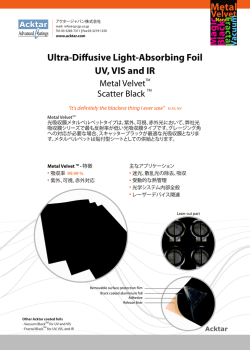
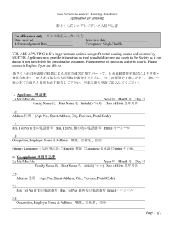
TSC 80251A1 TSC 80251A1 Extended 8–bit Microcontroller with Analog Interfaces Datasheet – 1996 TSC 80251A1 Table of Contents General Introduction Extended 8–bit Microcontroller with Analog Interfaces . . . . . . . . . . . . . . . . . 1. Section I: Introduction to TSC80251A1 Chapter 1: Core Features . . . . . . . . . . . . . . . . . . . . . . . . . . . . . . . . . . . . . . . I. 1.1 Chapter 2: Product Features . . . . . . . . . . . . . . . . . . . . . . . . . . . . . . . . . . . . . I. 2.1 Chapter 3: Block Diagram . . . . . . . . . . . . . . . . . . . . . . . . . . . . . . . . . . . . . . I. 3.1 Chapter 4: Pin Description . . . . . . . . . . . . . . . . . . . . . . . . . . . . . . . . . . . . . . I. 4.1 Section II: Design Information Chapter 1: Configuration and Memory Mapping . . . . . . . . . . . . . . . . . . II. 1.1 1.1. Introduction . . . . . . . . . . . . . . . . . . . . . . . . . . . . . . . . . . . . . . . . . . . . . . . . . . . . . . . . . . II. 1.1 1.2. Configuration . . . . . . . . . . . . . . . . . . . . . . . . . . . . . . . . . . . . . . . . . . . . . . . . . . . . . . . . II. 1.1 1.2.1. Page Mode and Wait States . . . . . . . . . . . . . . . . . . . . . . . . . . . . . . . . . . . . . . . . . . . . . . . . . . . . . . . . . . . . . II. 1.1 1.2.2. External Memory Signals . . . . . . . . . . . . . . . . . . . . . . . . . . . . . . . . . . . . . . . . . . . . . . . . . . . . . . . . . . . . . . II. 1.4 1.3. Memory Mapping . . . . . . . . . . . . . . . . . . . . . . . . . . . . . . . . . . . . . . . . . . . . . . . . . . . . . II. 1.6 1.3.1. Configuration Bytes . . . . . . . . . . . . . . . . . . . . . . . . . . . . . . . . . . . . . . . . . . . . . . . . . . . . . . . . . . . . . . . . . . . II. 1.6 1.3.2. Program/Code Memory . . . . . . . . . . . . . . . . . . . . . . . . . . . . . . . . . . . . . . . . . . . . . . . . . . . . . . . . . . . . . . . . II. 1.7 1.3.3. Data Memory . . . . . . . . . . . . . . . . . . . . . . . . . . . . . . . . . . . . . . . . . . . . . . . . . . . . . . . . . . . . . . . . . . . . . . . . II. 1.8 Rev. B (20/09/96) TSC 80251A1 1.3.4. Special Function Registers . . . . . . . . . . . . . . . . . . . . . . . . . . . . . . . . . . . . . . . . . . . . . . . . . . . . . . . . . . . . . . II. 1.9 Chapter 2: Parallel I/O Ports . . . . . . . . . . . . . . . . . . . . . . . . . . . . . . . . . . . II. 2.1 2.1. Introduction . . . . . . . . . . . . . . . . . . . . . . . . . . . . . . . . . . . . . . . . . . . . . . . . . . . . . . . . . . II. 2.1 2.2. I/O Configurations . . . . . . . . . . . . . . . . . . . . . . . . . . . . . . . . . . . . . . . . . . . . . . . . . . . . II. 2.3 2.3. Port 1 and Port 3 . . . . . . . . . . . . . . . . . . . . . . . . . . . . . . . . . . . . . . . . . . . . . . . . . . . . . . II. 2.3 2.4. Port 0 and Port 2 . . . . . . . . . . . . . . . . . . . . . . . . . . . . . . . . . . . . . . . . . . . . . . . . . . . . . . II. 2.4 2.5. Read–Modify–Write Instructions . . . . . . . . . . . . . . . . . . . . . . . . . . . . . . . . . . . . . . . . II. 2.5 2.6. Quasi–Bidirectional Port Operation . . . . . . . . . . . . . . . . . . . . . . . . . . . . . . . . . . . . . . II. 2.6 2.7. Port Loading . . . . . . . . . . . . . . . . . . . . . . . . . . . . . . . . . . . . . . . . . . . . . . . . . . . . . . . . . II. 2.7 2.8. External Memory Access . . . . . . . . . . . . . . . . . . . . . . . . . . . . . . . . . . . . . . . . . . . . . . . II. 2.7 Chapter 3: Timers/Counters . . . . . . . . . . . . . . . . . . . . . . . . . . . . . . . . . . . . II. 3.1 3.1. Introduction . . . . . . . . . . . . . . . . . . . . . . . . . . . . . . . . . . . . . . . . . . . . . . . . . . . . . . . . . . II. 3.1 3.2. Timer/Counter Operations . . . . . . . . . . . . . . . . . . . . . . . . . . . . . . . . . . . . . . . . . . . . . II. 3.2 3.3. Timer 0 . . . . . . . . . . . . . . . . . . . . . . . . . . . . . . . . . . . . . . . . . . . . . . . . . . . . . . . . . . . . . . II. 3.3 3.3.1. Mode 0 (13–bit Timer) . . . . . . . . . . . . . . . . . . . . . . . . . . . . . . . . . . . . . . . . . . . . . . . . . . . . . . . . . . . . . . . . . 3.3.2. Mode 1 (16–bit Timer) . . . . . . . . . . . . . . . . . . . . . . . . . . . . . . . . . . . . . . . . . . . . . . . . . . . . . . . . . . . . . . . . . 3.3.3. Mode 2 (8–bit Timer with Auto–Reload) . . . . . . . . . . . . . . . . . . . . . . . . . . . . . . . . . . . . . . . . . . . . . . . . . . 3.3.4. Mode 3 (Two 8–bit Timers) . . . . . . . . . . . . . . . . . . . . . . . . . . . . . . . . . . . . . . . . . . . . . . . . . . . . . . . . . . . . . II. 3.3 II. 3.4 II. 3.4 II. 3.5 3.4. Timer 1 . . . . . . . . . . . . . . . . . . . . . . . . . . . . . . . . . . . . . . . . . . . . . . . . . . . . . . . . . . . . . . II. 3.5 3.4.1. Mode 0 (13–bit Timer) . . . . . . . . . . . . . . . . . . . . . . . . . . . . . . . . . . . . . . . . . . . . . . . . . . . . . . . . . . . . . . . . . 3.4.2. Mode 1 (16–bit Timer) . . . . . . . . . . . . . . . . . . . . . . . . . . . . . . . . . . . . . . . . . . . . . . . . . . . . . . . . . . . . . . . . . 3.4.3. Mode 2 (8–bit Timer with Auto–Reload) . . . . . . . . . . . . . . . . . . . . . . . . . . . . . . . . . . . . . . . . . . . . . . . . . . 3.4.4. Mode 3 (Halt) . . . . . . . . . . . . . . . . . . . . . . . . . . . . . . . . . . . . . . . . . . . . . . . . . . . . . . . . . . . . . . . . . . . . . . . . II. 3.6 II. 3.6 II. 3.6 II. 3.6 3.5. Registers . . . . . . . . . . . . . . . . . . . . . . . . . . . . . . . . . . . . . . . . . . . . . . . . . . . . . . . . . . . . . II. 3.7 Chapter 4: Serial I/O Port . . . . . . . . . . . . . . . . . . . . . . . . . . . . . . . . . . . . . . II. 4.1 4.1. Introduction . . . . . . . . . . . . . . . . . . . . . . . . . . . . . . . . . . . . . . . . . . . . . . . . . . . . . . . . . . II. 4.1 Rev. B (20/09/96) TSC 80251A1 4.2. Modes of Operation . . . . . . . . . . . . . . . . . . . . . . . . . . . . . . . . . . . . . . . . . . . . . . . . . . . II. 4.3 4.3. Synchronous Mode (Mode 0) . . . . . . . . . . . . . . . . . . . . . . . . . . . . . . . . . . . . . . . . . . . . II. 4.3 4.3.1. Transmission (Mode 0) . . . . . . . . . . . . . . . . . . . . . . . . . . . . . . . . . . . . . . . . . . . . . . . . . . . . . . . . . . . . . . . . II. 4.4 4.3.2. Reception (Mode 0) . . . . . . . . . . . . . . . . . . . . . . . . . . . . . . . . . . . . . . . . . . . . . . . . . . . . . . . . . . . . . . . . . . . II. 4.4 4.4. Asynchronous Modes (Modes 1, 2 and 3) . . . . . . . . . . . . . . . . . . . . . . . . . . . . . . . . . . II. 4.4 4.4.1. Transmission (Modes 1, 2 and 3) . . . . . . . . . . . . . . . . . . . . . . . . . . . . . . . . . . . . . . . . . . . . . . . . . . . . . . . . . II. 4.5 4.4.2. Reception (Modes 1, 2 and 3) . . . . . . . . . . . . . . . . . . . . . . . . . . . . . . . . . . . . . . . . . . . . . . . . . . . . . . . . . . . II. 4.5 4.5. Framing Bit Error Detection (Modes 1, 2 and 3) . . . . . . . . . . . . . . . . . . . . . . . . . . . . II. 4.5 4.6. Overrun Error Detection (Modes 1, 2 and 3) . . . . . . . . . . . . . . . . . . . . . . . . . . . . . . . II. 4.5 4.7. Multiprocessor Communication (Modes 2 and 3) . . . . . . . . . . . . . . . . . . . . . . . . . . . II. 4.6 4.8. Automatic Address Recognition . . . . . . . . . . . . . . . . . . . . . . . . . . . . . . . . . . . . . . . . . II. 4.6 4.8.1. Given Address . . . . . . . . . . . . . . . . . . . . . . . . . . . . . . . . . . . . . . . . . . . . . . . . . . . . . . . . . . . . . . . . . . . . . . . II. 4.7 4.8.2. Broadcast Address . . . . . . . . . . . . . . . . . . . . . . . . . . . . . . . . . . . . . . . . . . . . . . . . . . . . . . . . . . . . . . . . . . . . II. 4.8 4.8.3. Reset Addresses . . . . . . . . . . . . . . . . . . . . . . . . . . . . . . . . . . . . . . . . . . . . . . . . . . . . . . . . . . . . . . . . . . . . . . II. 4.8 4.9. Baud Rates . . . . . . . . . . . . . . . . . . . . . . . . . . . . . . . . . . . . . . . . . . . . . . . . . . . . . . . . . . . II. 4.8 4.9.1. Internal Baud Rate Generator . . . . . . . . . . . . . . . . . . . . . . . . . . . . . . . . . . . . . . . . . . . . . . . . . . . . . . . . . . . II. 4.8 4.9.2. Baud Rate for Mode 0 . . . . . . . . . . . . . . . . . . . . . . . . . . . . . . . . . . . . . . . . . . . . . . . . . . . . . . . . . . . . . . . . . II. 4.8 4.9.3. Transmission Clock Selection . . . . . . . . . . . . . . . . . . . . . . . . . . . . . . . . . . . . . . . . . . . . . . . . . . . . . . . . . . . II. 4.9 4.9.4. Baud Rate for Modes 1 and 3 . . . . . . . . . . . . . . . . . . . . . . . . . . . . . . . . . . . . . . . . . . . . . . . . . . . . . . . . . . . II. 4.9 4.9.5. Baud Rate for Mode 2 . . . . . . . . . . . . . . . . . . . . . . . . . . . . . . . . . . . . . . . . . . . . . . . . . . . . . . . . . . . . . . . . II. 4.11 4.10. Registers . . . . . . . . . . . . . . . . . . . . . . . . . . . . . . . . . . . . . . . . . . . . . . . . . . . . . . . . . . . II. 4.12 Chapter 5: Pulse Measurement Unit . . . . . . . . . . . . . . . . . . . . . . . . . . . . . II. 5.1 5.1. Introduction . . . . . . . . . . . . . . . . . . . . . . . . . . . . . . . . . . . . . . . . . . . . . . . . . . . . . . . . . . II. 5.1 5.2. Description . . . . . . . . . . . . . . . . . . . . . . . . . . . . . . . . . . . . . . . . . . . . . . . . . . . . . . . . . . . II. 5.1 5.3. Registers . . . . . . . . . . . . . . . . . . . . . . . . . . . . . . . . . . . . . . . . . . . . . . . . . . . . . . . . . . . . . II. 5.4 Chapter 6: Event and Waveform Controller . . . . . . . . . . . . . . . . . . . . . . . II. 6.1 6.1. Introduction . . . . . . . . . . . . . . . . . . . . . . . . . . . . . . . . . . . . . . . . . . . . . . . . . . . . . . . . . . II. 6.1 6.2. Features . . . . . . . . . . . . . . . . . . . . . . . . . . . . . . . . . . . . . . . . . . . . . . . . . . . . . . . . . . . . . II. 6.1 6.3. PCA Mode . . . . . . . . . . . . . . . . . . . . . . . . . . . . . . . . . . . . . . . . . . . . . . . . . . . . . . . . . . . II. 6.2 Rev. B (20/09/96) TSC 80251A1 6.3.1. Timers/Counters . . . . . . . . . . . . . . . . . . . . . . . . . . . . . . . . . . . . . . . . . . . . . . . . . . . . . . . . . . . . . . . . . . . . . . II. 6.2 6.3.2. Compare/Capture Modules . . . . . . . . . . . . . . . . . . . . . . . . . . . . . . . . . . . . . . . . . . . . . . . . . . . . . . . . . . . . . II. 6.3 6.4. Enhanced PCA mode . . . . . . . . . . . . . . . . . . . . . . . . . . . . . . . . . . . . . . . . . . . . . . . . . II. 6.10 6.4.1. Timers/Counters . . . . . . . . . . . . . . . . . . . . . . . . . . . . . . . . . . . . . . . . . . . . . . . . . . . . . . . . . . . . . . . . . . . . . II. 6.11 6.5. Registers . . . . . . . . . . . . . . . . . . . . . . . . . . . . . . . . . . . . . . . . . . . . . . . . . . . . . . . . . . . . II. 6.13 Chapter 7: 8-bit Analog to Digital Converter . . . . . . . . . . . . . . . . . . . . . . II. 7.1 7.1. Introduction . . . . . . . . . . . . . . . . . . . . . . . . . . . . . . . . . . . . . . . . . . . . . . . . . . . . . . . . . . II. 7.1 7.2. Description . . . . . . . . . . . . . . . . . . . . . . . . . . . . . . . . . . . . . . . . . . . . . . . . . . . . . . . . . . . II. 7.1 7.3. Registers . . . . . . . . . . . . . . . . . . . . . . . . . . . . . . . . . . . . . . . . . . . . . . . . . . . . . . . . . . . . . II. 7.3 Chapter 8: Monitoring and Power Management . . . . . . . . . . . . . . . . . . . II. 8.1 8.1. Introduction . . . . . . . . . . . . . . . . . . . . . . . . . . . . . . . . . . . . . . . . . . . . . . . . . . . . . . . . . . II. 8.1 8.2. Power–On/Off Reset . . . . . . . . . . . . . . . . . . . . . . . . . . . . . . . . . . . . . . . . . . . . . . . . . . . II. 8.1 8.3. Power–Fail Detector . . . . . . . . . . . . . . . . . . . . . . . . . . . . . . . . . . . . . . . . . . . . . . . . . . . II. 8.2 8.4. Power–Off Flag . . . . . . . . . . . . . . . . . . . . . . . . . . . . . . . . . . . . . . . . . . . . . . . . . . . . . . . II. 8.4 8.5. Clock Prescaler . . . . . . . . . . . . . . . . . . . . . . . . . . . . . . . . . . . . . . . . . . . . . . . . . . . . . . . II. 8.4 8.6. Idle Mode . . . . . . . . . . . . . . . . . . . . . . . . . . . . . . . . . . . . . . . . . . . . . . . . . . . . . . . . . . . . II. 8.5 8.6.1 Entering Idle Mode . . . . . . . . . . . . . . . . . . . . . . . . . . . . . . . . . . . . . . . . . . . . . . . . . . . . . . . . . . . . . . . . . . . . II. 8.5 8.6.2 Exiting Idle Mode . . . . . . . . . . . . . . . . . . . . . . . . . . . . . . . . . . . . . . . . . . . . . . . . . . . . . . . . . . . . . . . . . . . . . II. 8.5 8.7. Power–Down Mode . . . . . . . . . . . . . . . . . . . . . . . . . . . . . . . . . . . . . . . . . . . . . . . . . . . . II. 8.6 8.7.1 Entering Power–Down Mode . . . . . . . . . . . . . . . . . . . . . . . . . . . . . . . . . . . . . . . . . . . . . . . . . . . . . . . . . . . . II. 8.7 8.7.2 Exiting Power–Down Mode . . . . . . . . . . . . . . . . . . . . . . . . . . . . . . . . . . . . . . . . . . . . . . . . . . . . . . . . . . . . . II. 8.7 8.8. Registers . . . . . . . . . . . . . . . . . . . . . . . . . . . . . . . . . . . . . . . . . . . . . . . . . . . . . . . . . . . . . II. 8.8 Chapter 9: Interrupt System . . . . . . . . . . . . . . . . . . . . . . . . . . . . . . . . . . . . II. 9.1 9.1. Introduction . . . . . . . . . . . . . . . . . . . . . . . . . . . . . . . . . . . . . . . . . . . . . . . . . . . . . . . . . . II. 9.1 9.2. Interrupt System Priorities . . . . . . . . . . . . . . . . . . . . . . . . . . . . . . . . . . . . . . . . . . . . . II. 9.2 Rev. B (20/09/96) TSC 80251A1 9.3. External Interrupts . . . . . . . . . . . . . . . . . . . . . . . . . . . . . . . . . . . . . . . . . . . . . . . . . . . . II. 9.4 9.4. Registers . . . . . . . . . . . . . . . . . . . . . . . . . . . . . . . . . . . . . . . . . . . . . . . . . . . . . . . . . . . . . II. 9.5 Section III: Electrical and Mechanical Information Chapter 1: DC Characteristics . . . . . . . . . . . . . . . . . . . . . . . . . . . . . . . . . . III. 1.1 Chapter 2: AC Characteristics . . . . . . . . . . . . . . . . . . . . . . . . . . . . . . . . . . III. 2.1 Chapter 3: ADC Characteristics . . . . . . . . . . . . . . . . . . . . . . . . . . . . . . . . III. 3.1 Chapter 4: EPROM Programming . . . . . . . . . . . . . . . . . . . . . . . . . . . . . . III. 4.1 4.1. Programming modes . . . . . . . . . . . . . . . . . . . . . . . . . . . . . . . . . . . . . . . . . . . . . . . . . . III. 4.1 4.2. Verify algorithm . . . . . . . . . . . . . . . . . . . . . . . . . . . . . . . . . . . . . . . . . . . . . . . . . . . . . III. 4.3 Chapter 5: TSC80C251A1: Packages . . . . . . . . . . . . . . . . . . . . . . . . . . . . III. 5.1 5.1. PLCC 44 . . . . . . . . . . . . . . . . . . . . . . . . . . . . . . . . . . . . . . . . . . . . . . . . . . . . . . . . . . . . III. 5.1 5.1.1. Mechanical Outline . . . . . . . . . . . . . . . . . . . . . . . . . . . . . . . . . . . . . . . . . . . . . . . . . . . . . . . . . . . . . . . . . . III. 5.1 5.1.2. Pin Assignment . . . . . . . . . . . . . . . . . . . . . . . . . . . . . . . . . . . . . . . . . . . . . . . . . . . . . . . . . . . . . . . . . . . . . III. 5.2 5.2. CQPJ 44 with Window . . . . . . . . . . . . . . . . . . . . . . . . . . . . . . . . . . . . . . . . . . . . . . . . III. 5.3 5.2.1. Mechanical Outline . . . . . . . . . . . . . . . . . . . . . . . . . . . . . . . . . . . . . . . . . . . . . . . . . . . . . . . . . . . . . . . . . . III. 5.3 5.2.2. Pin Assignment . . . . . . . . . . . . . . . . . . . . . . . . . . . . . . . . . . . . . . . . . . . . . . . . . . . . . . . . . . . . . . . . . . . . . III. 5.4 5.3. TQFP 44 . . . . . . . . . . . . . . . . . . . . . . . . . . . . . . . . . . . . . . . . . . . . . . . . . . . . . . . . . . . . III. 5.5 5.3.1. Mechanical Outline . . . . . . . . . . . . . . . . . . . . . . . . . . . . . . . . . . . . . . . . . . . . . . . . . . . . . . . . . . . . . . . . . . III. 5.5 5.3.2. Pin Assignment . . . . . . . . . . . . . . . . . . . . . . . . . . . . . . . . . . . . . . . . . . . . . . . . . . . . . . . . . . . . . . . . . . . . . III. 5.6 Rev. B (20/09/96) TSC 80251A1 Section IV: Ordering Information Ordering Information . . . . . . . . . . . . . . . . . . . . . . . . . . . . . . . . . . . . . . . . . IV. 1.1 Section V: TEMIC Addresses Sales Offices Addresses . . . . . . . . . . . . . . . . . . . . . . . . . . . . . . . . . . . . . . . . V. so.1 Representatives Addresses . . . . . . . . . . . . . . . . . . . . . . . . . . . . . . . . . . . . V. rep.1 Distributors Addresses . . . . . . . . . . . . . . . . . . . . . . . . . . . . . . . . . . . . . . . V. dist.1 Rev. B (20/09/96) TSC 80251A1 List of figures Section I: Introduction to TSC80251A1 Chapter 3: Block Diagram Figure 3.1. TSC80251A1 block diagram . . . . . . . . . . . . . . . . . . . . . . . . . . . . . . . . . . . . . . . . . . . . . . . . . . . . . . . . I. 3.1 Chapter 4: Pin Description Figure 4.1. TSC80251A1 pin description . . . . . . . . . . . . . . . . . . . . . . . . . . . . . . . . . . . . . . . . . . . . . . . . . . . . . . . . I. 4.1 Section II: Design Information Chapter 1: Configuration and Memory Mapping Figure 1.1. Bus structure in non–page mode and page mode . . . . . . . . . . . . . . . . . . . . . . . . . . . . . . . . . . . . . . . . II. 1.2 Figure 1.2. External bus cycle: code fetch, non–page mode . . . . . . . . . . . . . . . . . . . . . . . . . . . . . . . . . . . . . . . . . II. 1.2 Figure 1.3. External bus cycle: code fetch, page mode . . . . . . . . . . . . . . . . . . . . . . . . . . . . . . . . . . . . . . . . . . . . . II. 1.3 Figure 1.4. External bus cycle: code fetch with one RD#/PSEN# wait state in non–page mode . . . . . . . . . . . . . II. 1.3 Figure 1.5. Internal/external memory segments (RD1:0 = 00) . . . . . . . . . . . . . . . . . . . . . . . . . . . . . . . . . . . . . . . II. 1.4 Figure 1.6. Internal/external memory segments (RD1:0 = 01) . . . . . . . . . . . . . . . . . . . . . . . . . . . . . . . . . . . . . . . II. 1.5 Figure 1.7. Internal/external memory segments (RD1:0 = 10) . . . . . . . . . . . . . . . . . . . . . . . . . . . . . . . . . . . . . . . II. 1.5 Figure 1.8. Internal/external memory segments (RD1:0 = 11) . . . . . . . . . . . . . . . . . . . . . . . . . . . . . . . . . . . . . . . II. 1.6 Figure 1.9. Programmable Memory Mapping . . . . . . . . . . . . . . . . . . . . . . . . . . . . . . . . . . . . . . . . . . . . . . . . . . . . II. 1.7 Figure 1.10. Data Memory Mapping . . . . . . . . . . . . . . . . . . . . . . . . . . . . . . . . . . . . . . . . . . . . . . . . . . . . . . . . . . . II. 1.8 Figure 1.11. Configuration byte 0 . . . . . . . . . . . . . . . . . . . . . . . . . . . . . . . . . . . . . . . . . . . . . . . . . . . . . . . . . . . . II. 1.11 Figure 1.12. Configuration byte 1 . . . . . . . . . . . . . . . . . . . . . . . . . . . . . . . . . . . . . . . . . . . . . . . . . . . . . . . . . . . . II. 1.12 Chapter 2: Parallel I/O Ports Figure 2.1. Port 1 and Port 3 structure . . . . . . . . . . . . . . . . . . . . . . . . . . . . . . . . . . . . . . . . . . . . . . . . . . . . . . . . . . II. 2.4 Figure 2.2. Port 0 structure . . . . . . . . . . . . . . . . . . . . . . . . . . . . . . . . . . . . . . . . . . . . . . . . . . . . . . . . . . . . . . . . . . II. 2.4 Figure 2.3. Port 2 structure . . . . . . . . . . . . . . . . . . . . . . . . . . . . . . . . . . . . . . . . . . . . . . . . . . . . . . . . . . . . . . . . . . II. 2.5 Figure 2.4. Internal pull–up configurations . . . . . . . . . . . . . . . . . . . . . . . . . . . . . . . . . . . . . . . . . . . . . . . . . . . . . . II. 2.6 Chapter 3: Timers/Counters Figure 3.1. Timer/Counter x (x = 0 or 1) in mode 0 and mode 1 . . . . . . . . . . . . . . . . . . . . . . . . . . . . . . . . . . . . . II. 3.3 Figure 3.2. Timer/Counter x (x = 0 or 1) in mode 1 . . . . . . . . . . . . . . . . . . . . . . . . . . . . . . . . . . . . . . . . . . . . . . . II. 3.4 Figure 3.3. Timer/Counter x (x = 0 or 1) in mode 2 . . . . . . . . . . . . . . . . . . . . . . . . . . . . . . . . . . . . . . . . . . . . . . . II. 3.4 Figure 3.4. Timer/Counter in mode 3 : Two 8-bit Counters . . . . . . . . . . . . . . . . . . . . . . . . . . . . . . . . . . . . . . . . . II. 3.5 Figure 3.5. TCON register . . . . . . . . . . . . . . . . . . . . . . . . . . . . . . . . . . . . . . . . . . . . . . . . . . . . . . . . . . . . . . . . . . . II. 3.7 Rev. B (20/09/96) TSC 80251A1 Figure 3.6. TMOD register . . . . . . . . . . . . . . . . . . . . . . . . . . . . . . . . . . . . . . . . . . . . . . . . . . . . . . . . . . . . . . . . . . II. 3.8 Chapter 4: Serial I/O Port Figure 4.1. Serial Port block diagram . . . . . . . . . . . . . . . . . . . . . . . . . . . . . . . . . . . . . . . . . . . . . . . . . . . . . . . . . . II. 4.2 Figure 4.2. Mode 0 timings . . . . . . . . . . . . . . . . . . . . . . . . . . . . . . . . . . . . . . . . . . . . . . . . . . . . . . . . . . . . . . . . . . II. 4.3 Figure 4.3. Data frames (Modes 1, 2 and 3) . . . . . . . . . . . . . . . . . . . . . . . . . . . . . . . . . . . . . . . . . . . . . . . . . . . . . II. 4.5 Figure 4.4. Overrun Error (Modes 1, 2 and 3) . . . . . . . . . . . . . . . . . . . . . . . . . . . . . . . . . . . . . . . . . . . . . . . . . . . . II. 4.6 Figure 4.5. Clock transmission sources in mode 0 . . . . . . . . . . . . . . . . . . . . . . . . . . . . . . . . . . . . . . . . . . . . . . . . II. 4.9 Figure 4.6. Timer 1 as Baud Rate Generator in modes 1 and 3 . . . . . . . . . . . . . . . . . . . . . . . . . . . . . . . . . . . . . . II. 4.10 Figure 4.7. Internal Baud Rate Generator in modes 1 and 3 . . . . . . . . . . . . . . . . . . . . . . . . . . . . . . . . . . . . . . . . II. 4.10 Figure 4.8. Baud Rate Generator selection . . . . . . . . . . . . . . . . . . . . . . . . . . . . . . . . . . . . . . . . . . . . . . . . . . . . . II. 4.11 Figure 4.9. UART in mode 2 . . . . . . . . . . . . . . . . . . . . . . . . . . . . . . . . . . . . . . . . . . . . . . . . . . . . . . . . . . . . . . . . II. 4.11 Figure 4.10. BDRCON register . . . . . . . . . . . . . . . . . . . . . . . . . . . . . . . . . . . . . . . . . . . . . . . . . . . . . . . . . . . . . . II. 4.12 Figure 4.11. BRL register . . . . . . . . . . . . . . . . . . . . . . . . . . . . . . . . . . . . . . . . . . . . . . . . . . . . . . . . . . . . . . . . . . II. 4.13 Figure 4.12. SADDR register . . . . . . . . . . . . . . . . . . . . . . . . . . . . . . . . . . . . . . . . . . . . . . . . . . . . . . . . . . . . . . . II. 4.13 Figure 4.13. SADEN register . . . . . . . . . . . . . . . . . . . . . . . . . . . . . . . . . . . . . . . . . . . . . . . . . . . . . . . . . . . . . . . . II. 4.13 Figure 4.14. SBUF register . . . . . . . . . . . . . . . . . . . . . . . . . . . . . . . . . . . . . . . . . . . . . . . . . . . . . . . . . . . . . . . . . II. 4.13 Figure 4.15. SCON register . . . . . . . . . . . . . . . . . . . . . . . . . . . . . . . . . . . . . . . . . . . . . . . . . . . . . . . . . . . . . . . . . II. 4.14 Chapter 5: Pulse Measurement Unit Figure 5.1. PMU block diagram . . . . . . . . . . . . . . . . . . . . . . . . . . . . . . . . . . . . . . . . . . . . . . . . . . . . . . . . . . . . . . II. 5.1 Figure 5.2. PMU module n (n = 0, 1, 2) . . . . . . . . . . . . . . . . . . . . . . . . . . . . . . . . . . . . . . . . . . . . . . . . . . . . . . . . II. 5.2 Figure 5.3. PMU measurement . . . . . . . . . . . . . . . . . . . . . . . . . . . . . . . . . . . . . . . . . . . . . . . . . . . . . . . . . . . . . . . II. 5.2 Figure 5.4. Pulse measurement polarity . . . . . . . . . . . . . . . . . . . . . . . . . . . . . . . . . . . . . . . . . . . . . . . . . . . . . . . . . II. 5.3 Figure 5.5. PMCON register . . . . . . . . . . . . . . . . . . . . . . . . . . . . . . . . . . . . . . . . . . . . . . . . . . . . . . . . . . . . . . . . . II. 5.4 Figure 5.6. PMPER0 register . . . . . . . . . . . . . . . . . . . . . . . . . . . . . . . . . . . . . . . . . . . . . . . . . . . . . . . . . . . . . . . . . II. 5.4 Figure 5.7. PMPER1 register . . . . . . . . . . . . . . . . . . . . . . . . . . . . . . . . . . . . . . . . . . . . . . . . . . . . . . . . . . . . . . . . . II. 5.5 Figure 5.8. PMPER2 register . . . . . . . . . . . . . . . . . . . . . . . . . . . . . . . . . . . . . . . . . . . . . . . . . . . . . . . . . . . . . . . . . II. 5.5 Figure 5.9. PMSCAL0 register . . . . . . . . . . . . . . . . . . . . . . . . . . . . . . . . . . . . . . . . . . . . . . . . . . . . . . . . . . . . . . . II. 5.5 Figure 5.10. PMSCAL1 register . . . . . . . . . . . . . . . . . . . . . . . . . . . . . . . . . . . . . . . . . . . . . . . . . . . . . . . . . . . . . . II. 5.5 Figure 5.11. PMSCAL2 register . . . . . . . . . . . . . . . . . . . . . . . . . . . . . . . . . . . . . . . . . . . . . . . . . . . . . . . . . . . . . . II. 5.5 Figure 5.12. PMSTAT register . . . . . . . . . . . . . . . . . . . . . . . . . . . . . . . . . . . . . . . . . . . . . . . . . . . . . . . . . . . . . . . . II. 5.6 Figure 5.13. PMU register . . . . . . . . . . . . . . . . . . . . . . . . . . . . . . . . . . . . . . . . . . . . . . . . . . . . . . . . . . . . . . . . . . . II. 5.7 Figure 5.14. PMWID0 register . . . . . . . . . . . . . . . . . . . . . . . . . . . . . . . . . . . . . . . . . . . . . . . . . . . . . . . . . . . . . . . II. 5.7 Figure 5.15. PMWID1 register . . . . . . . . . . . . . . . . . . . . . . . . . . . . . . . . . . . . . . . . . . . . . . . . . . . . . . . . . . . . . . . II. 5.8 Figure 5.16. PMWID2 register . . . . . . . . . . . . . . . . . . . . . . . . . . . . . . . . . . . . . . . . . . . . . . . . . . . . . . . . . . . . . . . II. 5.8 Chapter 6: Event and Waveform Controller Figure 6.1. EWC Timer/Counter in PCA mode . . . . . . . . . . . . . . . . . . . . . . . . . . . . . . . . . . . . . . . . . . . . . . . . . . . II. 6.3 Figure 6.2. PCA 16–bit Capture Mode . . . . . . . . . . . . . . . . . . . . . . . . . . . . . . . . . . . . . . . . . . . . . . . . . . . . . . . . . II. 6.5 Figure 6.3. PCA Software Timer and High–Speed Output Modes . . . . . . . . . . . . . . . . . . . . . . . . . . . . . . . . . . . . II. 6.6 Rev. B (20/09/96) TSC 80251A1 Figure 6.4. PCA Watchdog Timer mode . . . . . . . . . . . . . . . . . . . . . . . . . . . . . . . . . . . . . . . . . . . . . . . . . . . . . . . . II. 6.8 Figure 6.5. PWM mode . . . . . . . . . . . . . . . . . . . . . . . . . . . . . . . . . . . . . . . . . . . . . . . . . . . . . . . . . . . . . . . . . . . . . II. 6.9 Figure 6.6. PWM variable duty cycle . . . . . . . . . . . . . . . . . . . . . . . . . . . . . . . . . . . . . . . . . . . . . . . . . . . . . . . . . II. 6.10 Figure 6.7. EWC Timer/Counter in EPCA mode . . . . . . . . . . . . . . . . . . . . . . . . . . . . . . . . . . . . . . . . . . . . . . . . II. 6.12 Chapter 7: 8–bit Analog to Digital Converter Figure 7.1. Analog Digital Converter structure . . . . . . . . . . . . . . . . . . . . . . . . . . . . . . . . . . . . . . . . . . . . . . . . . . . II. 7.1 Figure 7.2. ADAT register . . . . . . . . . . . . . . . . . . . . . . . . . . . . . . . . . . . . . . . . . . . . . . . . . . . . . . . . . . . . . . . . . . . II. 7.3 Figure 7.3. ADCON register . . . . . . . . . . . . . . . . . . . . . . . . . . . . . . . . . . . . . . . . . . . . . . . . . . . . . . . . . . . . . . . . . II. 7.3 Chapter 8: Power Monitoring and Management Figure 8.1. Behavior of the reset when the Power Supply is switched on . . . . . . . . . . . . . . . . . . . . . . . . . . . . . . . II. 8.1 Figure 8.2. Behavior of the reset when the Power Supply is switched off . . . . . . . . . . . . . . . . . . . . . . . . . . . . . . II. 8.2 Figure 8.3. Power Management timings . . . . . . . . . . . . . . . . . . . . . . . . . . . . . . . . . . . . . . . . . . . . . . . . . . . . . . . . II. 8.3 Figure 8.4. Block diagram of the digital filter . . . . . . . . . . . . . . . . . . . . . . . . . . . . . . . . . . . . . . . . . . . . . . . . . . . . II. 8.3 Figure 8.5. Waveforms of the VDD filtering . . . . . . . . . . . . . . . . . . . . . . . . . . . . . . . . . . . . . . . . . . . . . . . . . . . . . II. 8.4 Figure 8.6. Block diagram of the on–chip oscillator . . . . . . . . . . . . . . . . . . . . . . . . . . . . . . . . . . . . . . . . . . . . . . . II. 8.5 Figure 8.7. Symbolic of the on–chip oscillator . . . . . . . . . . . . . . . . . . . . . . . . . . . . . . . . . . . . . . . . . . . . . . . . . . . II. 8.5 Figure 8.8. PCON register . . . . . . . . . . . . . . . . . . . . . . . . . . . . . . . . . . . . . . . . . . . . . . . . . . . . . . . . . . . . . . . . . . . II. 8.8 Figure 8.9. PFILT register . . . . . . . . . . . . . . . . . . . . . . . . . . . . . . . . . . . . . . . . . . . . . . . . . . . . . . . . . . . . . . . . . . . II. 8.9 Figure 8.10. POWM register . . . . . . . . . . . . . . . . . . . . . . . . . . . . . . . . . . . . . . . . . . . . . . . . . . . . . . . . . . . . . . . . . II. 8.9 Figure 8.11. CKRL register . . . . . . . . . . . . . . . . . . . . . . . . . . . . . . . . . . . . . . . . . . . . . . . . . . . . . . . . . . . . . . . . . II. 8.10 Chapter 9: Interruption System Figure 9.1. Minimum pulse timings. . . . . . . . . . . . . . . . . . . . . . . . . . . . . . . . . . . . . . . . . . . . . . . . . . . . . . . . . . . . II. 9.4 Figure 9.2. IE0 register . . . . . . . . . . . . . . . . . . . . . . . . . . . . . . . . . . . . . . . . . . . . . . . . . . . . . . . . . . . . . . . . . . . . . II. 9.5 Figure 9.3. IE1 register . . . . . . . . . . . . . . . . . . . . . . . . . . . . . . . . . . . . . . . . . . . . . . . . . . . . . . . . . . . . . . . . . . . . . II. 9.6 Figure 9.4. IPH0 register . . . . . . . . . . . . . . . . . . . . . . . . . . . . . . . . . . . . . . . . . . . . . . . . . . . . . . . . . . . . . . . . . . . . II. 9.7 Figure 9.5. IPH1 register . . . . . . . . . . . . . . . . . . . . . . . . . . . . . . . . . . . . . . . . . . . . . . . . . . . . . . . . . . . . . . . . . . . . II. 9.8 Figure 9.6. IPL0 register . . . . . . . . . . . . . . . . . . . . . . . . . . . . . . . . . . . . . . . . . . . . . . . . . . . . . . . . . . . . . . . . . . . . II. 9.9 Figure 9.7. IPL1 register . . . . . . . . . . . . . . . . . . . . . . . . . . . . . . . . . . . . . . . . . . . . . . . . . . . . . . . . . . . . . . . . . . . II. 9.10 Section III: Electrical and Mechanical Information Chapter 1: DC Characteristics Figure 1.1. IPD Test Condition, Power–Down mode . . . . . . . . . . . . . . . . . . . . . . . . . . . . . . . . . . . . . . . . . . . . . III. 1.3 Figure 1.2. IDL Test Condition, Idle mode . . . . . . . . . . . . . . . . . . . . . . . . . . . . . . . . . . . . . . . . . . . . . . . . . . . . . III. 1.4 Figure 1.3. IDD Test Condition, Active mode . . . . . . . . . . . . . . . . . . . . . . . . . . . . . . . . . . . . . . . . . . . . . . . . . . III. 1.4 Chapter 2: AC Characteristics Rev. B (20/09/96) TSC 80251A1 Figure 2.1. External Instruction Bus Cycle in non–page mode . . . . . . . . . . . . . . . . . . . . . . . . . . . . . . . . . . . . . . III. 2.3 Figure 2.2. External Data Read Cycle in non–page mode . . . . . . . . . . . . . . . . . . . . . . . . . . . . . . . . . . . . . . . . . . III. 2.3 Figure 2.3. External Write Data Bus Cycle in non–page mode . . . . . . . . . . . . . . . . . . . . . . . . . . . . . . . . . . . . . . III. 2.4 Figure 2.4. External Instruction Bus Cycle in page mode . . . . . . . . . . . . . . . . . . . . . . . . . . . . . . . . . . . . . . . . . . III. 2.4 Figure 2.5. External Read Data Bus Cycle in page mode . . . . . . . . . . . . . . . . . . . . . . . . . . . . . . . . . . . . . . . . . . III. 2.5 Figure 2.6. External Write Data Bus Cycle in page mode . . . . . . . . . . . . . . . . . . . . . . . . . . . . . . . . . . . . . . . . . . III. 2.5 Figure 2.7. Serial Port Waveform – Shift Register mode . . . . . . . . . . . . . . . . . . . . . . . . . . . . . . . . . . . . . . . . . . III. 2.6 Chapter 3: ADC Characteristics Figure 3.1. A/D conversion characteristic . . . . . . . . . . . . . . . . . . . . . . . . . . . . . . . . . . . . . . . . . . . . . . . . . . . . . . III. 3.2 Chapter 4: EPROM Programming Figure 4.1. Setup for EPROM programming . . . . . . . . . . . . . . . . . . . . . . . . . . . . . . . . . . . . . . . . . . . . . . . . . . . . III. 4.1 Figure 4.2. Timings for EPROM programming . . . . . . . . . . . . . . . . . . . . . . . . . . . . . . . . . . . . . . . . . . . . . . . . . . III. 4.2 Figure 4.3. Setup for EPROM verification . . . . . . . . . . . . . . . . . . . . . . . . . . . . . . . . . . . . . . . . . . . . . . . . . . . . . III. 4.3 Figure 4.4. Timings for EPROM verification . . . . . . . . . . . . . . . . . . . . . . . . . . . . . . . . . . . . . . . . . . . . . . . . . . . III. 4.4 Chapter 5: Packages Figure 5.1. Plastic Lead Chip Carrier . . . . . . . . . . . . . . . . . . . . . . . . . . . . . . . . . . . . . . . . . . . . . . . . . . . . . . . . . III. 5.1 Figure 5.2. Ceramic Quad Pack J . . . . . . . . . . . . . . . . . . . . . . . . . . . . . . . . . . . . . . . . . . . . . . . . . . . . . . . . . . . . . III. 5.3 Figure 5.3. Thin Quad Flat Pack (Plastic) . . . . . . . . . . . . . . . . . . . . . . . . . . . . . . . . . . . . . . . . . . . . . . . . . . . . . . III. 5.5 Rev. B (20/09/96) TSC 80251A1 List of tables Section I: Introduction to TSC80251A1 Chapter 4: TSC80251A1 Pin Description Table 4.1. TSC80251A1 pin description . . . . . . . . . . . . . . . . . . . . . . . . . . . . . . . . . . . . . . . . . . . . . . . . . . . . . . . . . I. 4.2 Section II: Design Information Chapter 1: Configuration and Memory Mapping Table 1.1. Minimum Times to fetch two bytes of code . . . . . . . . . . . . . . . . . . . . . . . . . . . . . . . . . . . . . . . . . . . . . II. 1.7 Table 1.2. SFR addresses and Reset values . . . . . . . . . . . . . . . . . . . . . . . . . . . . . . . . . . . . . . . . . . . . . . . . . . . . . II. 1.10 Chapter 2: Parallel I/O Ports Table 2.1. Port pin descriptions . . . . . . . . . . . . . . . . . . . . . . . . . . . . . . . . . . . . . . . . . . . . . . . . . . . . . . . . . . . . . . . II. 2.1 Table 2.2. Instructions for external data moves . . . . . . . . . . . . . . . . . . . . . . . . . . . . . . . . . . . . . . . . . . . . . . . . . . . II. 2.8 Chapter 3: Timers/Counters Table 3.1. Timer/Counter SFRs . . . . . . . . . . . . . . . . . . . . . . . . . . . . . . . . . . . . . . . . . . . . . . . . . . . . . . . . . . . . . . . II. 3.1 Table 3.2. External signals . . . . . . . . . . . . . . . . . . . . . . . . . . . . . . . . . . . . . . . . . . . . . . . . . . . . . . . . . . . . . . . . . . . II. 3.2 Chapter 4: Serial I/O Port Table 4.1. Serial Port signals . . . . . . . . . . . . . . . . . . . . . . . . . . . . . . . . . . . . . . . . . . . . . . . . . . . . . . . . . . . . . . . . . II. 4.1 Table 4.2. Serial Port SFRs . . . . . . . . . . . . . . . . . . . . . . . . . . . . . . . . . . . . . . . . . . . . . . . . . . . . . . . . . . . . . . . . . . II. 4.1 Chapter 6: Event and Waveform Controller Table 6.1. PCA module modes . . . . . . . . . . . . . . . . . . . . . . . . . . . . . . . . . . . . . . . . . . . . . . . . . . . . . . . . . . . . . . . II. 6.4 Chapter 8: Power Monitoring and Management Table 8.1. Pin conditions in various modes . . . . . . . . . . . . . . . . . . . . . . . . . . . . . . . . . . . . . . . . . . . . . . . . . . . . . . II. 8.6 Chapter 9: Interruption System Table 9.1. Interrupt system signals . . . . . . . . . . . . . . . . . . . . . . . . . . . . . . . . . . . . . . . . . . . . . . . . . . . . . . . . . . . . II. 9.1 Table 9.2. Interrupt System SFRs . . . . . . . . . . . . . . . . . . . . . . . . . . . . . . . . . . . . . . . . . . . . . . . . . . . . . . . . . . . . . II. 9.2 Table 9.3. Level of Priority . . . . . . . . . . . . . . . . . . . . . . . . . . . . . . . . . . . . . . . . . . . . . . . . . . . . . . . . . . . . . . . . . . II. 9.3 Table 9.4. Interrupt priority within level . . . . . . . . . . . . . . . . . . . . . . . . . . . . . . . . . . . . . . . . . . . . . . . . . . . . . . . . II. 9.3 Section III: Electrical and Mechanical Information Chapter 1: DC Characteristics Table 1.2. DC characteristics . . . . . . . . . . . . . . . . . . . . . . . . . . . . . . . . . . . . . . . . . . . . . . . . . . . . . . . . . . . . . . . . III. 1.1 Rev. B (20/09/96) TSC 80251A1 Chapter 2: AC Characteristics Table 2.1. AC characteristics (Capacitive Loading = 50 pF) . . . . . . . . . . . . . . . . . . . . . . . . . . . . . . . . . . . . . . . . III. 2.1 Chapter 3: ADC Characteristics Table 3.1. A/D Converter electrical characteristics . . . . . . . . . . . . . . . . . . . . . . . . . . . . . . . . . . . . . . . . . . . . . . . III. 3.1 Chapter 4: EPROM Programming Table 4.1. EPROM programming configuration . . . . . . . . . . . . . . . . . . . . . . . . . . . . . . . . . . . . . . . . . . . . . . . . . III. 4.1 Table 4.2. EPROM verifying configuration . . . . . . . . . . . . . . . . . . . . . . . . . . . . . . . . . . . . . . . . . . . . . . . . . . . . . III. 4.3 Table 4.3. EPROM programming & verification characteristics ( TA = 21 to 275C ; VCC = 5V +/– 0.25V ; VSS= 0 ) . . . . . . . . . . . . . . . . . . . . . . . . . . . . . . . . . . . . . . . . . . . . III. 4.4 Chapter 5: Packages Table 5.1. PLCC Chip size . . . . . . . . . . . . . . . . . . . . . . . . . . . . . . . . . . . . . . . . . . . . . . . . . . . . . . . . . . . . . . . . . . III. 5.1 Table 5.2. PLCC Pin assignment . . . . . . . . . . . . . . . . . . . . . . . . . . . . . . . . . . . . . . . . . . . . . . . . . . . . . . . . . . . . . III. 5.2 Table 5.3. CQPJ Chip size . . . . . . . . . . . . . . . . . . . . . . . . . . . . . . . . . . . . . . . . . . . . . . . . . . . . . . . . . . . . . . . . . . III. 5.3 Table 5.4. CQPJ Pin assignment . . . . . . . . . . . . . . . . . . . . . . . . . . . . . . . . . . . . . . . . . . . . . . . . . . . . . . . . . . . . . III. 5.4 Table 5.5. TQFP Chip size . . . . . . . . . . . . . . . . . . . . . . . . . . . . . . . . . . . . . . . . . . . . . . . . . . . . . . . . . . . . . . . . . . III. 5.5 Table 5.6. TQFP Pin assignment . . . . . . . . . . . . . . . . . . . . . . . . . . . . . . . . . . . . . . . . . . . . . . . . . . . . . . . . . . . . . III. 5.6 Rev. B (20/09/96) TSC 80251A1 General Introduction TSC 80251A1 Extended 8–bit Microcontroller with Analog Interfaces The TSC80251A1 products are derivatives of the TEMIC Application Specific Microcontroller family based on the extended 8–bit C251 Architecture described below. This family of products are tailored to Microcontroller applications requiring analog interface structures. Three major peripheral blocks have been implemented to provide this facility to the designer: Analog to Digital Converter: 4 inputs at 8–bit resolution. Pulse Measurement Unit (PMU): 3 modules used to interface to smart analog sensors. Event and Waveform Controller (EWC): 5 programmable Counters e.g. for Pulse Width Modulation (PWM) or Compare/Capture functions. 1.1. Application focus Typical applications for these products are CD–ROM, Card or Barcode readers, Monitors, Car Navigation Systems, Airbag and Brake Systems, as well as all kinds of Industrial Control and Measurement Equipment. With the high instruction throughput, the TSC80251A1 products are focussing on all high–end 8–bit to 16–bit applications. They are also well suited to systems where a lower operating frequency is needed to reduce power consumption or Radio Frequency Interference (RFI), while maintaining a high level of CPU–power. 1.2. C251 Architecture The C251 Architecture at its lowest performance level, is Binary Code compatible with the 80C51 Architecture. Due to a 3–stage Instruction Pipeline, the CPU–Performance is increased by up to 5 times, using existing 80C51 code without any modification. Using the new C251 Instruction Set, the performance will be increased by up to 15 times, at the same clock rate. This performance enhancement is based on the 16–bit instruction bus and additional internal 8 and 16–bit data busses. The 24–bit address bus will allow an extension of the address space up to 16 Mbytes for future derivatives. Programming flexibility and C–code efficiency are both increased by the Register–based Architecture, the 64–Kbyte extended stack space, combined with the new Instruction Set. Combining the above features of the C251 core, the final code size could be reduced by a factor of 3, compared to an 80C51 implementation. All technical information in this document about core features are related to the core revision A (A–stepping). A new core revision, B/C (B–stepping) is presently in preparation. Both versions are upward compatible, so that no problem will appear if an A–stepping product is replaced by a B–stepping one. The major differences are some additional features in the configuration bytes and a modified emulator interface which will not affect existing application. 1. Rev. B (20/09/96) TSC 80251A1 A new document will be released as soon as the first TSC80251A1 product will be available in revision C. 1.3. TSC80251A1 Products The TSC80251A1 is available as a ROMless version (TSC80251A1) or with on–chip Mask Programmable ROM (TSC83251A1). The TSC87251A1 is an EPROM version or OTPROM (One Time Programmable) compatible with the Mask ROM version. The standard production packages are 44 pins PLCC or TQFP. The products can be delivered as 12 or 16 MHz versions at 5 Volts and in all major temperature ranges. 1.4. TSC80251A1 Documentation and Tools The following documentation and Starter tools are available to allow the full evaluation of the TEMIC TSC80251A1 product range: D “TSC80251A1 Microcontroller” Contains all information about the A1 derivatives (Block diagram, Memory mapping, Ports, Peripheral description, Electrical Mechanical and Ordering Information...). D “TSC80251 Programmer‘s Guide” Contains all information for the programmer. (Architecture, Instruction Set, Programming, Development tools) D “TSC80251 Design Guide” Contains a summary of available Application Notes for an easier usage of the TSC80251 and its major peripherals. D “TSC80251A1 Starter Kit” This kit enables the TSC80251A1 to be evaluated by the designer. It contains the following: G C–Compiler (limited to 2 Kbytes of code) G Assembler G Linker G TSC80251A1 Simulator G Optionally TSC80251A1 Evaluation Board with ROM–Monitor Please visit our WWW for updated versions in ZIP format. D “TSC80251A1 Development Tools” See chapter ”Development Tools” in the Programmer’s Guide” (Keil, Tasking, Hitex, Metalink, Nohau) D World Wide Web Please contact our WWW for possible updated information at http://www.temic.de D TSC80251 e–mail hotline: [email protected] 2. Rev. B (20/09/96) TSC 80251A1 Section I Introduction to TSC80251A1 TSC 80251A1 Core Features Based on the extended 8–bit C251 Architecture, the TSC80251A1 includes a complete set of new or improved C51 compatible peripherals as well as a 4 channels 8–bit A/D converter for communication with the analog environment. The key features of the new C251 Architecture are: D Register–based Architecture: G 40–byte Register File G Registers accessible as Bytes, Words, and Double Word. D 3-stage instruction pipeline D Enriched Instruction Set G 16–bit and 32–bit arithmetic and logic instructions G Compare and conditional jump instructions G Expanded set of Move instructions D Reduced Instruction Set G 189 generic instructions G Free space for additional instructions in the future G Additionally all 80C51 instructions are usable in binary mode D 16–bit internal code fetch D 64 Kbytes extended stack space D Maximum addressable memory 16 Mbytes The benefits of this new architecture are: D 5 times 80C51 performances in binary mode (80C51 binary code compatibility) D 15 times 80C51 performances in source mode (full architecture performance) D Up to a factor 3 of code size reduction (when a C for 80C51 program is recompiled in C251 language) D Reduction of RFI and power consumption (reduced operating frequency) D Complete System Development Support G Compatible with existing tools G New tools available: Compiler, Assembler, Debugger, ICE D Efficient C language support I. 1.1 Rev. B (20/09/96) TSC 80251A1 Product Features D 1 Kbyte of internal RAM D TSC83251A1: 24 Kbytes of on-chip masked ROM D TSC87251A1: 24 Kbytes of internal programmable ROM (OTP or UV erasable in window package) D TSC80251A1: ROMless version D External memory space (Code/Data): 256 Kbytes D Four 8–bit parallel I/O Ports (Ports 0, 1, 2 and 3 of the standard 80C51) D Two 16–bit Timers/Counters (Timers 0 and 1 of the standard 80C51) D Serial I/O Port : full duplex UART (80C51 compatible) D Three PMU: Pulse Measurement Unit for smart analog interface For each of the three modules: G 8–bit prescaler G 8–bit Timer for period and width measurements (duty cycle) G The measurement can start either on the rising or on the falling edge G One interrupt G Only one port line is used D EWC: Event and Waveform Controller G High-speed output G Compare/Capture inputs G PWM: Pulse Width Modulator G Watchdog Timer capabilities G Compatible with PCA: Programmable Counter Array (5 x 16–bit modules) D 8–bit Analog to Digital Converter G 4 channels G Conversion time: 600 clock periods (37.5 µs at 16 MHz) D Power Management G Power–On reset (integrated on the chip) G Power–Off flag (cold and warm resets) G Power-Fail detector G Power consumption reduction G Software programmable system clock G Idle and Power–Down modes D Power Supply: 5V ± 10% D Up to 16 MHz operation and three temperature ranges(*): G Commercial (0 to 70°C) G Industrial (–40 to +85°C) G Automotive (–40 to +125°C) D Packages: PLCC44, CQPJ44 (window) and TQFP44(**) *Please contact your sales office for availability of speed options ** Please contact your sales office for TQFP availability I. 2.1 Rev. B (20/09/96) TSC 80251A1 Block Diagram P2 (A15–8) P0 (AD7–0) XTAL2 XTAL1 PSEN# ALE/PROG# PORTS 0-3 OTPROM EPROM ROM RAM 24 Kbytes 1 Kbyte Clock Unit Clock System Prescaler Interrupt Handler Unit EA#/VPP 16–bit Memory Code 24-bit Data Address Bus 8-bit Data Bus 16-bit Inst. Bus 24-bit Prog. Counter Bus Bus Interface Unit RST Power–On Reset P1(A17) Timer 0 and Timer 1 8-bit Internal Bus Peripheral Interface Unit 16–bit Memory Address Event and Waveform Controller Pulse Measurement Unit P3(A16) UART CPU 4 x 8–bit ADC VDD0 VSS0 VSS1 AVDD AVSS Vref Figure 3.1. TSC80251A1 block diagram I. 3.1 Rev. B (20/09/96) TSC 80251A1 P0.3/AD3 P0.2/AD2 P0.1/AD1 P0.0/AD0 AVDD AVSS Vref P1.0/AN0 P1.1/AN1 P1.2/ECI/AN2 P1.3/CEX0/AN3 Pin Description P1.4/CEX1 P0.4/AD4 P1.5/PMI0/CEX2 P0.5/AD5 P1.6/PMI1/CEX3 P0.6/AD6 P1.7/A17/PMI2/CEX4 P0.7/AD7 RST EA#/VPP P3.0/RXD VDD0 TSC80251A1 P3.1/TXD VSS0 P3.2/INT0# ALE/PROG# P3.3/INT1# PSEN# P2.5/A13/PMI2 P2.4/A12/PMI1 P2.3/A11/PMI0 P2.1/A9 P2.2/A10 P2.0/A8 VSS1 XTAL1 P2.6/A14 XTAL2 P3.5/T1 P3.6/WR# P2.7/A15 P3.7/RD#/A16 P3.4/T0 Figure 4.1. TSC80251A1 pin description I. 4.1 Rev. B (20/09/96) TSC 80251A1 Table 4.1. TSC80251A1 pin description Pin Type Description P0.0:7 I/O Port 0 This is an 8–bit open–drain bidirectional I/O port. Port 0 pins that have 1s written to them float and can be used as high–impedance inputs. It is also Address/Data lines AD0:7, which are multiplexed lower address lines and data lines for external memory. External pull–ups are required during program verification. P1.0:7 I/O Port 1 This is an 8–bit bidirectional I/O port. It receives the low–order address byte during EPROM programming and verification. It serves also the functions of various special features: P1.0 AN0 : Analog Input 0, P1.1 AN1 : Analog input 1, P1.2 ECI : EWC External Clock input. AN2 : Analog input 2, P1.3 CEX0 : EWC module 0 Capture input/PWM output. AN3 : Analog input 3, P1.4 CEX1 : EWC module 1 Capture input/PWM output, P1.5 PMI0 : Pulse Measurement input 0, CEX2 : EWC module 2 Capture input/PWM output. P1.6 EAD6 : External Address line 6, PMI1 : Pulse Measurement input 1, CEX3 : EWC module 3 Capture input/PWM output. P1.7 A17 : Address line for the 256–Kbyte memory space depending on the byte CONFIG0 (See NO TAG), PMI2 : Pulse Measurement input 2, CEX4 : EWC module 4 Capture input/PWM output. P2.0:7 I/O Port 2 This is an 8–bit bidirectional I/O port with internal pull-ups. It is also Address lines A8:15, which are upper address lines for external memory. P3.0:7 I/O Port 3 This is an 8–bit bidirectional I/O port with internal pull-ups. It receives the high–order address bits during EPROM programming and verification. It serves also the functions of various special features: P3.0 RXD : Serial Port Receive Data input. P3.1 TXD : Serial Port Transmit Data output. P3.2 INT0# : External Interrupt 0. P3.3 INT1# : External Interrupt 1. P3.4 T0 : Timer 0 external clock input. P3.5 T1 : Timer 1 external clock input. P3.6 WR# : Write signal for external access. P3.7 A16 : Address line for 128–Kbyte and 256–Kbyte memory space depending on the byte CONFIG0, RD# : Read signal for external access, depending on the byte CONFIG0. I. 4.2 Rev. B (20/09/96) TSC 80251A1 Pin Type Description ALE/PROG# I/O PSEN# O Program Store Enable/Read signal output This output is asserted for a memory address range that depends on bits RD0 and RD1 in configuration byte CONFIG0. EA#/VPP I External Access Enable/Programming Supply Voltage This input directs program memory accesses to on–chip or off–chip code memory. For EA# = 0, all program memory accesses are off-chip. For EA# = 1, an access is on-chip OTPROM/EPROM/ROM if the address is within the range of the on–chip OTPROM/EPROM/ROM; otherwise the access is off-chip. The value of EA# is latched at reset. For devices without ROM on-chip, EA# must be strapped to ground. It receives also the Programming Supply Voltage VPP during EPROM programming operation. Vref I Voltage reference for the Analog to Digital Converter VSS0 GND Digital Ground VDD0 PWR Digital Supply Voltage VSS1 GND Digital Ground AVSS GND Analog Ground AVDD PWR Analog Supply Voltage RST I Reset input to the chip Holding this pin high for 64 oscillator periods while the oscillator is running resets the device. The Port pins are driven to their reset conditions when a voltage greater than VIH1 is applied, whether or not the oscillator is running. This pin has an internal pull-down resistor which allows the device to be reset by connecting a capacitor between this pin and VDD0. Asserting RST when the chip is in Idle mode or Power–Down mode returns the chip to normal operation. XTAL1 I Input to the on–chip inverting oscillator amplifier To use the internal oscillator, a crystal/resonator circuit is connected to this pin. If an external oscillator is used, its output is connected to this pin. XTAL1 is the clock source for internal timing. XTAL2 O Output of the on–chip inverting oscillator amplifier To use the internal oscillator, a crystal/resonator circuit is connected to this pin. If an external oscillator is used, leave XTAL2 unconnected. Address Latch Enable/Program Pulse It signals the start of an external bus cycle and indicates that valid address information is available on lines A15:8 and AD7:0. An external latch can use ALE to demultiplex the address from address/data bus. It is also used as the Program Pulse input PROG#, during EPROM programming. I. 4.3 Rev. B (20/09/96) TSC 80251A1 Section II Design Information TSC 80251A1 Configuration and Memory Mapping 1.1. Introduction The C251 Architecture provides generic configuration and memory addressing capabilities. However, the products based on this Architecture may provide various derivative features. The configuration and memory mapping features of the TSC80251A1 derivatives are detailed in this section. 1.2. Configuration The TSC80251A1 derivatives provide design flexibility by configuring certain operating features during the device reset. These features fall into the following categories: external/internal memory access operation, external memory interface, source/binary mode opcodes, selection of bytes stored on the stack by an interrupt. The choice of internal program/code or external memory access is made through the External Access pin (EA#, see paragraph 1.3.2.). The internal memories of the TSC80251A1 derivatives are detailed in paragraph 1.3. “Memory Mapping”. The choice of external memory interface is detailed in this section: Page Mode and Wait States External Memory Signals The choice of source or binary mode and the interrupt processing are discussed in the TSC80251 Programmers’ Guide. These settings are made based on two configuration bytes (CONFIG0 and CONFIG1, see Figure 1.11. and Figure 1.12. at the end of this chapter). 1.2.1. Page Mode and Wait States This part discusses the choice of external cycle speed configuration. All the external bus cycles are based on states which are made of two cycles of the internal oscillator. The external XTAL1 frequency can be internally divided by the oscillator to reduce the power consumption (See “Power Monitoring and Management” chapter) and the speed of the external cycles is then reduced accordingly. TSC80251A1 derivatives use two 8–bit ports (P0, P2) to multiplex a 16–bit address bus and an 8–bit data bus. The first configuration is multiplexing the lower 8–bit address bus and the 8–bit data bus on Port 0; this is the non–page mode which is compatible with the 80C51 derivatives. The second configuration is multiplexing the upper 8–bit address bus and the 8–bit data bus on Port 2; this is the page mode which improves performance. This bus structure is shown on Figure 1.1 and is configured by the PAGE bit of CONFIG0 byte. II. 1.1 Rev. B (20/09/96) TSC 80251A1 TSC80251A1 P2 A15:8 TSC80251A1 A15:8 D7:0 AD7:0 Latch P0 A7:0 D7:0 P2 A7:0 Latch A15:8 RAM/ A15:8/D7:0 A15:8 EPROM/ Flash A7:0 P0 A7:0 RAM/ EPROM/ Flash D7:0 Non–page Mode Page Mode Figure 1.1. Bus structure in non–page mode and page mode The Figure 1.2. highlights the non–page mode configuration with a code fetch cycle. One state is used to latch A7:0 on Port 0, then the data are transferred during the second state. State 1 State 2 OSC ALE RD#/PSEN# A7:0 P0 A17/A16/P2 D7:0 A17/A16/A15:8 Figure 1.2. External bus cycle: code fetch, non–page mode II. 1.2 Rev. B (20/09/96) TSC 80251A1 State 1 State 3 State 2 OSC ALE RD#/PSEN# A17/A16/A7:0 A17/A16/P0 A15:8 A17/A16/A7:0 D7:0 D7:0 Figure 1.3. External bus cycle: code fetch, page mode Three configuration bits are provided to introduce Wait States and modulate the access time depending on the external devices. One wait state can be added to extend the address latch time using the XALE bit in CONFIG0 byte. Another wait state can also be added to extend the data access time once the multiplexed addresses have been latched. Figure 1.4. shows a code fetch in non–page mode with one such wait state. The Wait State A bit (WSA bit in CONFIG0 byte) adds one state for external program/code and data accesses (See segments FF:, FE:, 00: in paragraph 1.2.2.). The Wait State B bit (WSB bit in CONFIG1 byte) adds one state for external data accesses only (See segment 01: in paragraph 1.2.2.). State 1 State 2 State 3 OSC ALE RD#/PSEN# P0 A17/A16/P2 A7:0 D7:0 A17/A16/A15:8 Figure 1.4. External bus cycle: code fetch with one RD#/PSEN# wait state in non–page mode II. 1.3 Rev. B (20/09/96) TSC 80251A1 1.2.2. External Memory Signals For easy reference to the C51 Architecture, it is convenient to consider the 24–bit linear address space of the C251 Architecture as 256 segments of 64 Kbytes (from segment 00: to segment FF:). Some of these segments are reserved to map the internal registers and, in this section, we only consider the segments which allows to access to the external memory. In the TSC80251A1 derivatives only four segments of the 24–bit internal address space (00:, 01:, FE:, FF:) are implemented to address the external memory. This allows a maximum program or data memory space of 256 Kbytes. Various configurations are possible, depending on the Read configuration bits (RD1:0) which are set in CONFIG0 byte. 1.2.2.1. How to address 256 Kbytes The maximum external memory is provided when RD1:0 = 00, as shown on Figure 1.5. PSEN# is used as a read signal and WR# is used as a write signal. Eighteen address bits are provided externally (P0, P2, A16, A17) to control 256 Kbytes in four segments. In this configuration, the program/code and data spaces share the same external memory segments. Internal Spaces Read/Write Signals Segments Addresses External Memory A17, A16, P2, P0 Program/Code Data PSEN# PSEN#/WR# FF: 11 FE: 10 01: 01 00: 00 256 Kbytes A17/A16 11 FF: 10 FE: FF: 11 01 01: FE: 10 00 00: 01: 01 00: 00 Figure 1.5. Internal/external memory segments (RD1:0 = 00) 1.2.2.2. How to address 128 Kbytes One I/O pin (P1.7/A17) is saved if 128 Kbytes of external memory are enough, as shown on Figure 1.6. (RD1:0 = 01). PSEN# is used as a read signal and WR# is used as a write signal. Seventeen address bits are provided externally (P0, P2, A16) to control 128 Kbytes in two segments. In this configuration, the program/code and data spaces share the same external memory segments which are replicated twice in each internal space. II. 1.4 Rev. B (20/09/96) TSC 80251A1 Internal Spaces Program/Code Data Read/Write Signals PSEN# PSEN#/WR# Segments Addresses A16, P2, P0 External Memory FF: 1 FE: 0 01: 1 A16 00: 0 1 01:, FF: FF: 1 0 00:, FE: FE: 0 01: 1 00: 0 128 Kbytes Figure 1.6. Internal/external memory segments (RD1:0 = 01) 1.2.2.3. How to address 64 Kbytes Two I/O pins (P1.7/A17, P3.7/A16/RD#) are saved if 64 Kbytes of external memory are enough, as shown on Figure 1.7. (RD1:0 = 10). PSEN# is used as a read signal and WR# is used as a write signal. Sixteen address bits are provided externally (P0, P2) to control 64 Kbytes in one segment. In this configuration, the program/code and data share the same external memory segment which is replicated four times in each internal space. Internal Spaces Read/Write Signals Segments Addresses External Memory P2, P0 FF: Program/Code FE: PSEN# 01: 00: 64 Kbytes 00:, 01:, FE:, FF: FF: Data PSEN#/WR# FE: 01: 00: Figure 1.7. Internal/external memory segments (RD1:0 = 10) 1.2.2.4. How to keep C51 memory compatibility The last configuration provides a full compatibility with the C51 Architecture, as shown on Figure 1.8. (RD1:0 = 11). PSEN# is used as a read signal for program/code memory read while RD# is used as a read signal and WR# is used as a write signal for data memory accesses. Sixteen address II. 1.5 Rev. B (20/09/96) TSC 80251A1 bits are provided externally (Port 0, Port 2). In this configuration, the program/code fits in one read–only external memory segment and the data fits in another read–write external memory segment. Each segment is replicated four times in one internal space. Internal Spaces Read/Write Signals Segments FF: Addresses External Memory P2, P0 FE: Program/Code PSEN# 01: 2x64 Kbytes 00: FF: Data RD#/WR# 00:, 01:, FE:, FF: 00:, 01:, FE:, FF: FE: 01: 00: Figure 1.8. Internal/external memory segments (RD1:0 = 11) 1.3. Memory Mapping The specific internal memories of the TSC80251A1 derivatives fall into the following categories: 2 Configuration bytes, 24 Kbytes on–chip ROM or EPROM/OTP program/code memory, 1 Kbyte on–chip RAM data memory, Special Function Registers (SFRs). 1.3.1. Configuration Bytes The Configuration bytes, CONFIG0 and CONFIG1, are detailed in Figure 1.11. and Figure 1.12. During reset they are read from a specific ROM area. For the TSC87251A1 EPROM and OTPROM versions, these bytes are programmable in an EPROM area (See “EPROM programming” chapter). For the TSC83251A1 masked ROM versions, these bytes are additional information provided in a masked ROM area. For the TSC80251A1 ROMless versions, these bytes are configured in factory according to the part number (See “Ordering Information”). These bytes are not accessible by the user during operation and they do not appear in the Memory Mapping of the TSC80251A1 derivatives. II. 1.6 Rev. B (20/09/96) TSC 80251A1 Program/code Program/code External Memory Space Segments FF:FFFFh 40 Kbytes FF:6000h FF:5FFFh EA#=0 24 Kbytes FF:0000h FE:FFFFh 64 Kbytes FE:0000h FD:FFFFh Reserved 02:0000h 01:FFFFh Internal Memory ROM Code 8 Kbytes 16 Kbytes 128 Kbytes 01:0000h 00:FFFFh 00:0000h Figure 1.9. Programmable Memory Mapping 1.3.2. Program/Code Memory The split of the internal and external program/code memory space is shown on Figure 1.9. If EA# is tied to a high level, the 24–Kbyte internal program memory are mapped in the lower part of segment FF: where the C251 core jumps after reset. The rest of the program/code memory space is mapped to the external memory (See paragraph 1.2.2. to determine to which external memory location each segment actually maps). If EA# is tied to a low level, the internal program/code memory is not used and all the accesses are directed to the external memory. Table 1.1. lists the minimum times to fetch on–chip and external memory. Table 1.1. Minimum Times to fetch two bytes of code Type of code memory State times On–chip code memory 1 External memory (page mode) 2 External memory (nonpage mode) 4 For the TSC87251A1 EPROM and OTPROM versions, the internal program/code is programmable in EPROM (See “EPROM programming” chapter). For the TSC83251A1 masked ROM versions, the internal program/code is provided in a masked ROM. For the TSC80251A1 ROMless versions, there is no possible internal program/code and EA# must be tied to a low level. In fact, for TSC83251A1 and TSC87251A1 versions, the upper 8 Kbytes of the internal ROM are also mapped in the data space (See paragraph 1.3.3.). II. 1.7 Rev. B (20/09/96) TSC 80251A1 Note: Special care should be taken when the Program Counter (PC) increments: If your program executes exclusively from on–chip ROM/OTPROM/EPROM (not from external memory), beware of executing code from the upper eight bytes of the on–chip ROM/OTPROM/EPROM (FF:5FF8h–FF:5FFFh). Because of its pipeline capability, the 80C251A1 may attempt to prefetch code from external memory (at an address above FF:5FF8H/FF:5FFFH) and thereby disrupt I/O Ports 0 and 2. Fetching code constants from these eight bytes does not affect Ports 0 and 2. When PC reaches the end of segment FF:, it loops to the reset address FF:0000h (for compatibility with the C51 architecture). When PC increments beyond the end of segment FE:, it continues at the reset address FF:0000h (linearity). When PC increments beyond the end of segment 01:, it loops to the beginning of segment 00: (this prevents it going into the reserved area). 1.3.3. Data Memory Data External Memory Space Internal Memory ROM Code Data Segments FF:FFFFh 40 Kbytes 24 Kbytes EA#=0 64 Kbytes FF:6000h FF:5FFFh FF:0000h FE:FFFFh 8 Kbytes EA#=1 FE:0000h FD:FFFFh Reserved 02:0000h 01:FFFFh 16 Kbytes 64 Kbytes 8 Kbytes EMAP=1 01:0000h 00:EFFFh 00:E000h EMAP=0 RAM Data 1 Kbyte 55 Kbytes FC:0000h 32 bytes reg. Figure 1.10. Data Memory Mapping The split of the internal and external data memory space is shown on Figure 1.10. All the TSC80251A1 derivatives feature an internal 1 Kbyte RAM. This memory is mapped in the data space just over the 32 bytes of registers area (See TSC80251 Programmers’ Guide). Hence, the lowermost 96 bytes of the internal RAM are bit addressable. This internal RAM is not accessible through the program/code memory space. For computation with the internal ROM code of the TSC83251A1 and TSC87251A1 versions, its upper 8 Kbytes are also mapped in the data space if the EPROM Map configuration bit is cleared (EMAP bit in CONFIG1 byte, see Figure 1.2. ). However, if EA# is tied to a low level and the TSC80251A1 derivative is running as a ROMless, the code is actually fetched in the corresponding external memory (i.e. the upper 8 Kbytes of the lower 24 Kbytes of segment FF:). If EMAP bit is set, the internal ROM is not accessible through the data memory space. II. 1.8 Rev. B (20/09/96) TSC 80251A1 All the accesses to the portion of the data space with no internal memory mapped onto are redirected to the external memory, see paragraph 1.2.2. to determine to which external memory location each segment actually maps. 1.3.4. Special Function Registers The Special Function Registers (SFRs) of the TSC80251A1 derivatives fall into the following categories: D C251 core registers (SP, SPH, DPL, DPH, DPXL, PSW, PSW1, ACC, B) D Port registers (P0, P1, P2, P3) D Timer registers (TCON, TMOD, TL0, TL1, TH0, TH1) D Serial Port and Baud Rate Generator registers (SCON, SBUF, SADDR, SADEN, BDRCON, BRL) D Pulse Measurement Unit registers (PMU, PMCON, PMSCAL0, PMSCAL1, PMSCAL2, PMPER0, PMPER1, PMPER2, PMWID0, PMWID1, PMWID2) D Event and Waveform Controller registers: G Counters (CCON, CMOD, CMOD0, CMOD1, CMOD2, COF, CRC, CIE, CL0, CL1, CL2, CL3, CL4, CH0, CH1, CH2, CH3, CH4) G Compare/Capture (CCAPM0, CCAPM1, CCAPM2, CCAPM3, CCAPM4, CCAPL0, CCAPL1, CCAPL2, CCAPL3, CCAPL4, CCAPH0, CCAPH1, CCAPH2, CCAPH3, CCAPH4) D Analog to Digital Converter registers (ADCON, ADAT) D Power monitoring/management and clock control registers (PCON, PFILT, POWM, CKRL) D Interrupt system registers (IE0, IE1, IPL0, IPL1, IPH0, IPH1) SFRs are placed in a reserved internal memory segment S: which is not represented in the internal memory mapping. The relative addresses within S of these SFRs within S: are provided together with their reset values in Table 1.2. . All the SFRs are bit–addressable using the C251 Instruction Set. The C251 core registers are in italics in this table and they are described in the TSC80251 Programmers’ Guide. The other registers are detailed in the following sections which fully describe each peripheral unit. II. 1.9 Rev. B (20/09/96) TSC 80251A1 Table 1.2. SFR addresses and Reset values F8h CH = CH0 0000 0000 F0h CCAP0H XXXX XXXX CCAP1H XXXX XXXX B** 0000 0000 E8h CCAP2H XXXX XXXX CCAP3H XXXX XXXX CCAP4H XXXX XXXX CMOD3 0000 0000 CH1 0000 0000 CH2 0000 0000 CH3 0000 0000 CH4 0000 0000 CL = CL0 0000 0000 CCAP0L XXXX XXXX CCAP1L XXXX XXXX CCAP2L XXXX XXXX CCAP3L XXXX XXXX CCAP4L XXXX XXXX CMOD2 0000 0000 E0h ACC** 0000 0000 COF XXX0 0000 CRC 0000 0000 CIE XXX0 0000 CL1 0000 0000 CL2 0000 0000 CL3 0000 0000 CL4 0000 0000 D8h CCON 0000 0000 CMOD 00XX X000 CCAPM0 X000 0000 CCAPM1 X000 0000 CCAPM2 X000 0000 CCAPM3 X000 0000 CCAPM4 X000 0000 CMOD1 0000 0000 D0h PSW** 0000 0000 PSW1** 0000 0000 ADCON XXX0 0X00 ADAT* XXXX XXXX C8h C0h B8h IPL0 0000 0000 SADEN 0000 0000 SPH** 0000 0000 B0h P3 1111 1111 IE1 X000 0000 IPL1 0000 0000 IPH1 0000 0000 A8h IE0 0000 0000 SADDR 0000 0000 PMSCAL0 XXXX XXXX PMSCAL1 XXXX XXXX A0h P2 1111 1111 IPH0 0000 0000 PMSCAL2 XXXX XXXX PMCON X000 X000 PMSTAT X000 X000 PMPER0* PMWID0* PMPER1* PMWID1* PMPER2* PMWID2* XXXX XXXXh XXXX XXXXh XXXX XXXXh XXXX XXXXh XXXX XXXXh XXXX XXXXh SBUF XXXX XXXX BRL 0000 0000 BDRCON XXX0 0000 98h SCON 0000 0000 PMU XXXX XXX0 90h P1 1111 1111 88h TCON 0000 0000 TMOD 0000 0000 TL0 0000 0000 TL1 0000 0000 TH0 0000 0000 80h P0 1111 1111 SP** 0000 0111 DPL** 0000 0000 DPH** 0000 0000 DPXL** 0000 0001 0/8 1/9 2/A 3/B 4/C TH1 0000 0000 5/D CKRL 0000 1000 POWM 0XX0 0000 PFILT 0000 1000 PCON 000X 0000 6/E 7/F * read only **C251 core registers described in the TSC80251 Programmer’s Guide reserved S:00h – S7Fh unimplemented S:100h – S:1FFh unimplemented II. 1.10 Rev. B (20/09/96) TSC 80251A1 CONFIG0 Configuration byte 0 – 7 – 6 WSA 5 Bit Number Bit Mnemonic 7 – 7 – 5 WSA 4 XALE 3, 2 RD1, RD0 1 PAGE 0 SRC XALE 4 RD1 3 RD0 2 PAGE 1 SRC 0 Description Reserved The value read from this bit is indeterminate. Do not set this bit. Reserved The value read from this bit is indeterminate. Do not set this bit. Wait State A bit Clear to generate one external wait state for memory regions 00:, FE:, and FF:. Set for no wait states for these regions. Extend ALE bit Clear to extend the time of the ALE pulse from TOSC to 3.TOSC, which adds one external wait state. Set the time of the ALE pulse to TOSC. RD# and PSEN# Function Select bits RD1 RD0 RD# P1.7 PSEN# Range 0 0 A16 A17 PSEN# is the read signal for both external data and program address space (256 Kbytes). 0 1 A16 I/O pin PSEN# is the read signal for both external data and program address space (128 Kbytes). 1 0 P3.7 I/O pin PSEN# is the read signal for both external data and program address space (64 Kbytes). 1 1 RD# I/O pin 64–Kbyte code memory space 64–Kbyte data memory space Page Mode Select bit Clear for page–mode with A15:8/D7:0 on Port 2, and A7:0 on Port0. Set for non page–mode with A15:8 on Port 2, and A7:0/D7:0 on Port 0 (compatible with 80C51microcontrollers). Source Mode/Binary Mode Select bit Clear for Binary Mode (Binary Code compatible with 80C51 microcontrollers) Set for Source Mode. Figure 1.11. Configuration byte 0 Note: To configure the TSC80251A1 in C51 microcontroller mode, use the following bit values in CONFIG0: 1101 1110B. II. 1.11 Rev. B (20/09/96) TSC 80251A1 CONFIG1 Configuration byte 1 – – – INTR WSB – – EMAP 7 6 5 4 3 2 1 0 Bit Number Bit Mnemonic 7 – Reserved The value read from this bit is indeterminate. Do not set this bit. 6 – Reserved The value read from this bit is indeterminate. Do not set this bit. 5 – Reserved The value read from this bit is indeterminate. Do not set this bit. 4 INTR Interrupt Mode bit Clear so that the interrupts push 2 bytes onto the stack (the 2 lower bytes of the PC register). Set so that the interrupts push 4 bytes onto the stack (the 3 bytes of the PC register and the PSW1 register). 3 WSB Wait State B bit Clear to generate one external wait state for memory region 01:. Set for no wait states for region 01:. 2 – Reserved The value read from this bit is indeterminate. Do not set this bit. 1 – Reserved The value read from this bit is indeterminate. Do not set this bit. 0 EMAP Description EPROM Map bit Clear to map the upper 8 Kbytes of on–chip code memory (FF:3000h-FF:5FFFh) to 00:C000h-00:FFFFh. Set to map the upper 12 Kbytes of on–chip code memory to FF:3000h-FF:5FFFh. Figure 1.12. Configuration byte 1 Note: To configure the TSC80251A1 in C51 microcontroller mode, use the following bit values in CONFIG1: 1110 0111B. II. 1.12 Rev. B (20/09/96) TSC 80251A1 Parallel I/O Ports 2.1. Introduction The TSC80251A1 uses input/output (I/O) Ports to exchange data with external devices. In addition to performing general–purpose I/O, some Ports are capable of external memory operations; others allow for alternate functions. All four TSC80251A1 I/O Ports are bidirectional. Each Port contains a latch, an output driver and an input buffer. Port 0 and Port 2 output drivers and input buffers facilitate external memory operations. Port 0 drives the lower address byte onto the parallel address bus and Port 2 drives the upper address byte onto the bus. In non–page mode, the data is multiplexed with the lower address byte on Port 0. In page mode, the data is multiplexed with the upper address byte on Port 2. All Port 1 and Port 3 pins serve for both general–purpose I/O and alternate functions (See Table 2.1. ). Table 2.1. Port pin descriptions Pin Name Type Alternate Pin Name Alternate Description Alternate Type P0.0 I/O AD0 Address/Data line 0 (Non–page mode) Address line 0 (Page mode) I/O P0.1 I/O AD1 Address/Data line 1 (Non–page mode) Address line 1 (Page mode) I/O P0.2 I/O AD2 Address/Data line 2 (Non–page mode) Address line 2 (Page mode) I/O P0.3 I/O AD3 Address/Data line 3 (Non–page mode) Address line 3 (Page mode) I/O P0.4 I/O AD4 Address/Data line 4 (Non–page mode) Address line 4 (Page mode) I/O P0.5 I/O AD5 Address/Data line 5 (Non–page mode) Address line 5 (Page mode) I/O P0.6 I/O AD6 Address/Data line 6 (Non–page mode) Address line 6 (Page mode) I/O P0.7 I/O AD7 Address/Data line 7 (Non–page mode) Address line 7 (Page mode) I/O II. 2.1 Rev. B (20/09/96) TSC 80251A1 Pin Name Type Alternate Pin Name Alternate Description P1.0 I/O AN0 Analog input 0 I P1.1 I/O AN1 Analog input 1 I P1.2 I/O ECI AN2 EWC external clock input Analog input 2 I I P1.3 I/O CEX0 AN3 EWC module 0 Capture input/PWM output Analog input 3 I/O I P1.4 I/O CEX1 EWC module 1 Capture input/PWM output I/O P1.5 I/O PMI0 CEX2 PMU input 0 EWC module 2 Capture input/PWM output I I/O P1.6 I/O PMI1 CEX3 PMU input 1 EWC module 3 Capture input/PWM output I I/O P1.7 I/O A17 PMI2 CEX4 Address line 17 PMU input 2 EWC module 4 Capture input/PWM output I/O I I/O Pin Name Type Alternate Pin Name P2.0 I/O A8 Address line 8 (Non–page mode) Address/Data line 8 (Page mode) I/O P2.1 I/O A9 Address line 9 (Non–page mode) Address/Data line 9 (Page mode) I/O P2.2 I/O A10 Address line 10 (Non–page mode) Address/Data line 10 (Page mode) I/O P2.3 I/O A11 Address line 11 (Non–page mode) Address/Data line 11 (Page mode) I/O P2.4 I/O A12 Address line 12 (Non–page mode) Address/Data line 12 (Page mode) I/O P2.5 I/O A13 Address line 13 (Non–page mode) Address/Data line 13 (Page mode) I/O P2.6 I/O A14 Address line 14 (Non–page mode) Address/Data line 14 (Page mode) I/O P2.7 I/O A15 Address line 15 (Non–page mode) Address/Data line 15 (Page mode) I/O Alternate Description Alternate Type Alternate Type II. 2.2 Rev. B (20/09/96) TSC 80251A1 Pin Name Type Alternate Pin Name Alternate Description Alternate Type P3.0 I/O RXD Serial Port Receive Data input I P3.1 I/O TXD Serial Port Transmit Data output O P3.2 I/O INT0# External Interrupt 0 I P3.3 I/O INT1# External Interrupt 1 I P3.4 I/O T0 Timer 0 input I P3.5 I/O T1 Timer 1 input I P3.6 I/O WR# Write signal to external memory O P3.7 I/O RD# A16 Read signal to external memory Address line 16 O I/O Notes: EWC = Event Waveform Controller PMU = Pulse Measurement Unit PWM = Pulse Width Modulation 2.2. I/O Configurations Each Port SFR operates via type–D latches, as illustrated in Figure 2.1. for Ports 1 and 3. A CPU “write to latch” signal initiates transfer of internal bus data into the type–D latch. A CPU “read latch” signal transfers the latched Q output onto the internal bus. Similarly, a “read pin” signal transfers the logical level of the Port pin. Some Port data instructions activate the “read latch” signal while others activate the “read pin” signal. Latch instructions are referred to as Read–Modify–Write instructions (See “Read–Modify–Write Instructions” paragraph). Each I/O line may be independently programmed as input or output. 2.3. Port 1 and Port 3 Figure 2.1. shows the structure of Ports 1 and 3, which have internal pull–ups. An external source can pull the pin low. Each Port pin can be configured either for general–purpose I/O or for its alternate input or output function (See Table 2.1. ). To use a pin for general–purpose output, set or clear the corresponding bit in the Px register (x = 1 or 3). To use a pin for general–purpose input, set the bit in the Px register. This turns off the output driver FET. To configure a pin for its alternate function, set the bit in the Px register. When the latch is set, the “alternate output function” signal controls the output level (See Figure 2.1. ). The operation of Ports 1 and 3 is discussed further in “Quasi–Bidirectional Port Operation” paragraph. II. 2.3 Rev. B (20/09/96) TSC 80251A1 VDD Alternate Output Function Read Latch Internal Bus Write to Latch Internal pull–up P3.x P1.x D P1.x Q P3.x Latch CL Q# Read Pin Alternate Input Function Figure 2.1. Port 1 and Port 3 structure 2.4. Port 0 and Port 2 Ports 0 and 2 are used for general–purpose I/O or as the external address/data bus. Port 0, shown in Figure 2.2. , differs from the other Ports in not having internal pull–ups. Figure 2.3. shows the structure of Port 2. An external source can pull a Port 2 pin low. To use a pin for general–purpose output, set or clear the corresponding bit in the Px register (x = 0 or 2). To use a pin for general–purpose input set the bit in the Px register to turn off the output driver FET. Address Data Read Latch Internal Bus Write to Latch D CL P0.x Latch Control VDD Q P0.x Q# 1 0 Read Pin Figure 2.2. Port 0 structure II. 2.4 Rev. B (20/09/96) TSC 80251A1 Address Data VDD Control Read Latch Internal Bus D Write to Latch CL P2.x Latch Q P2.x 1 0 Q# Read Pin Figure 2.3. Port 2 structure When Port 0 and Port 2 are used for an external memory cycle, an internal control signal switches the output–driver input from the latch output to the internal address/data line. “External Memory Access” paragraph discusses the operation of Port 0 and Port 2 as the external address/data bus. Notes: Port 0 and Port 2 are precluded from use as general purpose I/O Ports when used as address/data bus drivers. Port 0 internal pull–ups assist the logic–one output for memory bus cycles only. Except for these bus cycles, the pull–up FET is off. All other Port 0 outputs are open–drain. 2.5. Read–Modify–Write Instructions Some instructions read the latch data rather than the pin data. The latch based instructions read the data, modify the data and then rewrite the latch. These are called “Read–Modify–Write” instructions. Below is a complete list of these special instructions. When the destination operand is a Port or a Port bit, these instructions read the latch rather than the pin: Instruction Description Example ANL logical AND ANL P1,A ORL logical OR ORL P2,A XRL logical EX–OR XRL P3,A JBC jump if bit = 1 and clear bit JBC P1.1, LABEL CPL complement bit CPL P3.0 INC increment INC P2 II. 2.5 Rev. B (20/09/96) TSC 80251A1 Instruction Description Example DEC decrement DEC P2 DJNZ decrement and jump if not zero DJNZ P3, LABEL MOV Px.y, C move carry bit to bit y of Port x MOV P1.5, C CLR Px.y clear bit y of Port x CLR P2.4 SET Px.y set bit y of Port x SET P3.3 It is not obvious the last three instructions in this list are Read–Modify–Write instructions. These instructions read the Port (all 8 bits), modify the specifically addressed bit and write the new byte back to the latch. These Read–Modify–Write instructions are directed to the latch rather than the pin in order to avoid possible misinterpretation of voltage (and therefore, logic) levels at the pin. For example, a Port bit used to drive the base of an external bipolar transistor cannot rise above the transistor’s base–emitter junction voltage (a value lower than VIL). With a logic one written to the bit, attempts by the CPU to read the Port at the pin are misinterpreted as logic zero. A read of the latch rather than the pin returns the correct logic–one value. 2.6. Quasi–Bidirectional Port Operation Port 1, Port 2 and Port 3 have fixed internal pull–ups and are referred to as “quasi–bidirectional” Ports. When configured as an input, the pin impedance appears as logic one and sources current in response to an external logic zero condition. Port 0 is a “true bidirectional” pin. The pin floats when configured as input. Resets write logical one to all Port latches. If logical zero is subsequently written to a Port latch, it can be returned to input conditions by a logical one written to the latch. VDD VDD VDD 2 Osc. Periods p1 Q# from Port Latch p2 p3 n Input data Read Port Pin Figure 2.4. Internal pull–up configurations Note: Port latch values change near the end of Read–Modify–Write instruction cycles. Output buffers (and therefore the pin state) update early in the instruction after the Read–Modify–Write instruction cycle. II. 2.6 Rev. B (20/09/96) TSC 80251A1 Logical zero–to–one transitions in Port 1, Port 2 and Port 3 use an additional pull–up to aid this logic transition (See Figure 2.4. ). This increases switch speed. The extra pull–up briefly sources 100 times normal internal circuit current. The internal pull–ups are field–effect transistors rather than linear resistors. Pull–ups consist of three p–channel FET (pFET) devices. A pFET is on when the gate senses logical zero and off when the gate senses logical one. pFET #1 is turned on for two oscillator periods immediately after a zero–to–one transition in the Port latch. A logical one at the Port pin turns on pFET #3 (a weak pull–up) through the inverter. This inverter and pFET pair form a latch to drive logical one. pFET #2 is a very weak pull–up switched on whenever the associated nFET is switched off. This is traditional CMOS switch convention. Current strengths are 1/10 that of pFET #3. 2.7. Port Loading Output buffers of Port 1, Port 2 and Port 3 can each sink 1.6 mA at logic zero. These Port pins can be driven by open–collector and open–drain devices. Logic zero–to–one transitions occur slowly as limited current pulls the pin to a logic–one condition (See Figure 2.4. ). A logic–zero input turns off pFET #3. This leaves only pFET #2 weakly in support of the transition. In external bus mode, Port 0 output buffers each sink 3.2 mA at logic zero. However, the Port 0 pins require external pull–ups to drive external gate inputs. External circuits must be designed to limit current requirements to these conditions. 2.8. External Memory Access The external bus structure is different for page mode and non–page mode. In non–page mode (used by 80C51 microcontrollers), Port 2 outputs the upper address byte; the lower address byte and the data are multiplexed on Port 0. In page mode, the upper address byte and the data are multiplexed on Port 2, while Port 0 outputs the lower address byte. The TSC80251A1 CPU writes FFh to the Port 0 register for all external memory bus cycles. This overwrites previous information in Port 0. In contrast, the Port 2 register is unmodified for external bus cycles. When address bits or data bits are not on the Port 2 pins, the bit values in Port 2 appear on the Port 2 pins. In non–page mode, Port 0 uses a strong internal pull–up FET to output ones or a strong internal pull–down FET to output zeros for the lower address byte and the data. Port 0 is in a high–impedance state for data input. In page mode, Port 0 uses a strong internal pull–up FET to output ones or a strong internal pull–down FET to output zeros for the lower address byte or a strong internal pull–down FET to output zeros for the upper address byte. In non–page mode, Port 2 uses a strong internal pull–up FET to output ones or a strong internal pull–down FET to output zeros for the upper address byte. In page mode, Port 2 uses a strong internal pull–up FET to output ones or a strong internal pull–down FET to output zeros for the upper address byte and data. Port 2 is in a high–impedance state for data input. Note: In external bus mode Port 0 outputs do not require external pull–ups. There are two types of external memory accesses: external program memory and external data memory. External program memories use signal PSEN# as a read strobe. 80C51 microcontrollers II. 2.7 Rev. B (20/09/96) TSC 80251A1 use RD# (read) or WR# (write) to strobe memory for data accesses. Depending on its RD0 and RD1 configuration bits, the TSC80251A1 uses PSEN# or RD# for data reads (See “Configuration bits RD0 and RD1”). During instruction fetches, external program memory can transfer instructions with 16–bit addresses for binary compatible code or with the external bus configured for extended memory addressing (17–bit or 18–bit). External data memory transfers use an 8–bit, 16–bit, 17–bit or 18–bit address bus, depending on the instruction and the configuration of the external bus. Table 2.2. lists the instructions that can be used for the these bus widths. Table 2.2. Instructions for external data moves Bus width Instructions 8 MOVX @Ri MOV @Rm MOV dir8 16 MOVX @DPTR MOV @WRj MOV @WRj+dis MOV dir16 17 MOV @DRk MOV @DRk+dis 18 MOV @DRk MOV @DRk+dis Note: Avoid MOV P0 instructions for external memory accesses. These instructions can corrupt input code bytes at Port 0. External signal ALE (address latch enable) facilitates external address latch capture. The address byte is valid after the ALE pin drives VOL . For write cycles, valid data is written to Port 0 just prior to the write pin (WR#) asserting VOL . Data remains valid until WR# is undriven. For read cycles, data returned from external memory must appear at Port 0 before the read pin (RD#) is undriven. Waits states, by definition, affect bus–timing. II. 2.8 Rev. B (20/09/96) TSC 80251A1 Timers/Counters 3.1. Introduction The TSC80251A1 contains two general–purpose, 16–bit Timers/Counters. Although they are identified as Timer 0 and Timer 1, you can independently configure each to operate in a variety of modes as a Timer or as an event Counter. Each Timer employs two 8–bit Timer registers, used separately or in cascade, to maintain the count. Timer registers and associated control and capture registers are implemented as addressable special function registers (SFRs). Table 3.1. briefly describes the SFRs referred to in this chapter. Two of the SFRs provide programmable control of the Timers as follows: Timer/Counter Mode Control register (TMOD). Timer/Counter Control register (TCON) for Timer 0 and Timer 1. These registers are described at the end of this chapter. Table 3.1. Timer/Counter SFRs Mnemonic Description Address TL0 TH0 Timer 0 registers Used separately as two 8–bit Counters or in cascade as one 16–bit Counter. Counts an internal clock signal with frequency FOSC /12 (Timer operation) or an external input (event Counter operation). S:8Ah S:8Ch TL1 TH1 Timer 1 registers Used separately as two 8–bit Counters or in cascade as one 16–bit Counter. Counts an internal clock signal with frequency FOSC /12 (Timer operation) or an external input (event Counter operation). S:8Bh S:8Dh TCON Timer 0/1 Control register Contains the run control bits, overflow flags, interrupt flags and interrupt type control bits for Timer 0 and Timer 1. S:88h TMOD Timer 0/1 Mode Control register Contains the mode select bits, Counter/Timer select bits and external control gate bits for Timer 0 and Timer 1. S:89h II. 3.1 Rev. B (20/09/96) TSC 80251A1 Table 3.2. describes the external signals referred to in this chapter. Table 3.2. External signals Description Multiplexed With Mnemonic Type INT0# I External Interrupt 0 This input sets the IE0 interrupt flag in TCON register. IT0 selects the triggering method: IT0 = 1 selects edge–triggered (high–to–low); IT0 = 0 selects level–triggered (active low). INT0# also serves as external run control for Timer 0, when selected by GATE0 bit in TCON register. P3.2 INT1# I External Interrupt 1 This input sets the IE1 interrupt flag in TCON register. IT1 selects the triggering method: IT1 = 1 selects edge–triggered (high–to–low); IT1 =0 selects level–triggered (active low). INT1# also serves as external run control for Timer 1, when selected by GATE1 bit in TCON register. P3.3 T0 I Timer 0 External Clock Input When Timer 0 operates as a Counter, a falling edge on the T0 pin increments the count. P3.4 T1 I Timer 1 External Clock Input When Timer 1 operates as a Counter, a falling edge on the T1 pin increments the count. P3.5 3.2. Timer/Counter Operations For example, a basic operation is Timer registers THx and TLx (x = 0 or 1) connected in cascade to form a 16–bit Timer. Setting the run control bit (TRx) turns the Timer on by allowing the selected input to increment TLx. When TLx overflows it increments THx; when THx overflows it sets the Timer overflow flag (TFx) in TCON register. Setting the run control bit does not clear the THx and TLx Timer registers. Timer registers can be accessed to obtain the current count or to enter preset values. Timer 0 and Timer 1 can also be controlled by external pin INTx# to facilitate pulse width measurements. The C\Tx# control bit selects Timer operation or Counter operation by selecting the divided–down system clock or external pin Tx as the source for the counted signal. For Timer operation (C/Tx# = 0), the Timer register counts the divided–down system clock. The Timer register is incremented once every peripheral cycle, i.e. once every six states. Since six states equals 12 oscillator periods (clock cycles), the Timer clock rate is FOSC /12. For Counter operation (C/Tx# = 1), the Timer register counts the negative transitions on the Tx external input pin. When the sample of the external inputs is high in one cycle and low in the next, the Counter is incremented. Since it takes 12 states (24 oscillator periods) to recognize a negative transition, the maximum count rate is 1/24 of the oscillator frequency. There are no restrictions on II. 3.2 Rev. B (20/09/96) TSC 80251A1 the duty cycle of the external input signal, but to ensure that a given level is sampled at least once before it changes, it should be held for at least one full peripheral cycle. 3.3. Timer 0 Timer 0 functions as either a Timer or event Counter in four modes of operation. Figure 3.1. , Figure 3.3. and Figure 3.4. show the logical configuration of each mode. Timer 0 is controlled by the four low–order bits of TMOD register (See Figure 3.6. ) and bits 0, 1, 4 and 5 of TCON register (See Figure 3.5. ). TMOD register selects the method of Timer gating (GATE0), Timer or Counter operation (T/C0#), and mode of operation (M10 and M00). TCON register provides Timer 0 control functions: overflow flag (TF0), run control bit (TR0), interrupt flag (IE0), and interrupt type control bit (IT0). For normal Timer operation (GATE0 = 0), setting TR0 allows TL0 to be incremented by the selected input. Setting GATE0 and TR0 allows external pin INT0# to control Timer operation. This setup can be used to make pulse width measurements. Timer 0 overflow (count rolls over from all 1s to all 0s) sets TF0 flag generating an interrupt request. 3.3.1. Mode 0 (13–bit Timer) Mode 0 configures Timer 0 as an 13–bit Timer which is set up as an 8–bit Timer (TH0 register) with a modulo 32 prescaler implemented with the lower five bits of TL0 register (See Figure 3.1. ). The upper three bits of TL0 register are indeterminate and should be ignored. Prescaler overflow increments TH0 register. OSC 12 C/Tx = 0 C/Tx = 1 Tx TLx THx (5 bits) (8 bits) TFx Timer Interrupt x OVERFLOW TRx GATEx INTx# Figure 3.1. Timer/Counter x (x = 0 or 1) in mode 0 and mode 1 II. 3.3 Rev. B (20/09/96) TSC 80251A1 3.3.2. Mode 1 (16–bit Timer) Mode 1 configures Timer 0 as a 16–bit Timer with TH0 and TL0 connected in cascade (See Figure 3.2. ). The selected input increments TL0. OSC 12 C/Tx = 0 C/Tx = 1 Tx TLx THx (8 bits) (8 bits) TFx Timer Interrupt x OVERFLOW TRx GATEx INTx# Figure 3.2. Timer/Counter x (x = 0 or 1) in mode 1 3.3.3. Mode 2 (8–bit Timer with Auto–Reload) Mode 2 configures Timer 0 as an 8–bit Timer (TL0 register) that automatically reloads from TH0 register (See Figure 3.3. ). TL0 overflow sets TF0 flag in TCON register and reloads TL0 with the contents of TH0, which is preset by software. When the interrupt request is serviced, hardware clears TF0. The reload leaves TH0 unchanged. OSC 12 C/Tx = 0 Tx C/Tx = 1 TLx (8 bits) TFx Timer Interrupt x CONTROL RELOAD TRx GATEx INTx# THx (8 bits) Figure 3.3. Timer/Counter x (x = 0 or 1) in mode 2 II. 3.4 Rev. B (20/09/96) TSC 80251A1 3.3.4. Mode 3 (Two 8–bit Timers) Mode 3 configures Timer 0 such that registers TL0 and TH0 operate as separate 8–bit Timers (See Figure 3.4. ). This mode is provided for applications requiring an additional 8–bit Timer or Counter. TL0 uses the Timer 0 control bits C/T0# and GATE0 in TMOD register, and TR0 and TF0 in TCON register in the normal manner. TH0 is locked into a Timer function (counting FOSC /12) and takes over use of the Timer 1 interrupt (TF1) and run control (TR1) bits. Thus, operation of Timer 1 is restricted when Timer 0 is in mode 3. OSC 12 C/T0 = 0 C/T0 = 1 T0 TL0 (8 bits) TF0 Timer Interrupt 0 TF1 Timer Interrupt 1 CONTROL TR0 GATE0 INT0# OSC 12 TH0 (8 bits) CONTROL TR1 Figure 3.4. Timer/Counter in mode 3 : Two 8-bit Counters 3.4. Timer 1 Timer 1 functions as either a Timer or event Counter in three modes of operation. Figure 3.1. and Figure 3.3. show the logical configuration for modes 0, 1, and 2. Timer 1’s mode 3 is a hold–count mode. Timer 1 is controlled by the four high–order bits of TMOD register (See Figure 3.6. ) and bits 2, 3, 6 and 7 of TCON register (See Figure 3.5. ). TMOD register selects the method of Timer gating (GATE1), Timer or Counter operation (C/T1#), and mode of operation (M11 and M01). TCON register provides Timer 1 control functions: overflow flag (TF1), run control bit (TR1), interrupt flag (IE1), and interrupt type control bit (IT1). Timer 1 operation in modes 0, 1 and 2 is identical to Timer 0. Timer 1 can serve as the Baud Rate Generator for the Serial Port. Mode 2 is best suited for this purpose. For normal Timer operation (GATE1 = 0), setting TR1 allows Timer register TL1 to be incremented by the selected input. Setting GATE1 and TR1 allows external pin INT1# to control Timer operation. This setup can be used to make pulse width measurements. II. 3.5 Rev. B (20/09/96) TSC 80251A1 Timer 1 overflow (count rolls over from all 1s to all 0s) sets the TF1 flag generating an interrupt request. When Timer 0 is in mode 3, it uses Timer 1’s overflow flag (TF1) and run control bit (TR1). For this situation, use Timer 1 only for applications that do not require an interrupt (such as a Baud Rate Generator for the Serial Port) and switch Timer 1 in and out of mode 3 to turn it off and on. 3.4.1. Mode 0 (13–bit Timer) Mode 0 configures Timer 1 as a 13–bit Timer, which is set up as an 8–bit Timer (TH1 register) with a modulo–32 prescaler implemented with the lower 5 bits of the TL1 register (See Figure 3.1. ). The upper 3 bits of TL1 register are ignored. Prescaler overflow increments TH1 register. 3.4.2. Mode 1 (16–bit Timer) Mode 1 configures Timer 1 as a 16–bit Timer with TH1 and TL1 connected in cascade (See Figure 3.2. ). The selected input increments TL1. 3.4.3. Mode 2 (8–bit Timer with Auto–Reload) Mode 2 configures Timer 1 as an 8–bit Timer (TL1 register) with automatic reload from TH1 register on overflow (See Figure 3.3. ). Overflow from TL1 sets overflow flag TF1 in TCON register and reloads TL1 with the contents of TH1, which is preset by software. The reload leaves TH1 unchanged. 3.4.4. Mode 3 (Halt) Placing Timer 1 in mode 3 causes it to halt and hold its count. This can be used to halt Timer 1 when TR1 run control bit is not available, i.e. when Timer 0 is in mode 3. II. 3.6 Rev. B (20/09/96) TSC 80251A1 3.5. Registers TCON (088h) Timer/Counter Control register TF1 TR1 TF0 TR0 IE1 IT1 IE0 IT0 7 6 5 4 3 2 1 0 Bit Number Bit Mnemonic 7 TF1 Timer 1 Overflow flag Cleared by hardware when processor vectors to interrupt routine. Set by hardware on Timer/Counter overflow. 6 TR1 Timer 1 Run Control bit Clear to turn off Timer/Counter 1. Set to turn on Timer/Counter 1. 5 TF0 Timer 0 Overflow flag Cleared by hardware when processor vectors to interrupt routine. Set by hardware on Timer/Counter overflow. 4 TR0 Timer 0 Run Control bit Clear to turn off Timer/Counter 0. Set to turn on Timer/Counter 0. 3 IE1 Interrupt 1 Edge flag Cleared by hardware when interrupt is processed if edge-triggered (See IT1). Set by hardware when external interrupt is detected out INT1# pin. 2 IT1 Interrupt 1 Type Control bit Clear to select low level active (level triggered) for external interrupt 1. Set to select falling edge active (edge triggered) for external interrupt 1. 1 IE0 Interrupt 0 Edge flag Cleared by hardware when interrupt is processed if edge-triggered (See IT0). Set by hardware when external interrupt is detected out INT0# pin. 0 IT0 Interrupt 0 Type Control bit Clear to select low level active (level triggered) for external interrupt 0. Set to select falling edge active (edge triggered) for external interrupt 0. Description Reset value = 0000 0000B Figure 3.5. TCON register II. 3.7 Rev. B (20/09/96) TSC 80251A1 TMOD (089h) Timer/Counter Mode register GATE1 C/T1# M11 M01 GATE0 C/T0# M10 M00 7 6 5 4 3 2 1 0 Bit Number Bit Mnemonic 7 GATE1 Timer 1 Gating Control bit Clear to enable Timer 1 whenever TR1 bit is set. Set to enable Timer/Counter 1 only while INT1# pin is high and TR1 bit is set. 6 C/T1# Timer 1 Counter/Timer Select bit Cleared for Timer operation (input from internal system clock). Set for Counter operation (input from T1 input pin). 5 M11 4 M01 3 GATE0 Timer 0 Gating Control bit Clear to enable Timer 0 whenever TR0 bit is set. Set to enable Timer/Counter 0 only while INT0# pin is high and TR0 bit is set. 2 C/T0# Timer 0 Counter/Timer Select bit Cleared for Timer operation (input from internal system clock) Set for Counter operation (input from T0 input pin). 1 M10 0 M00 Description Timer 1 Mode Select bits M11 M01 Operating mode 0 0 Mode 0: 8–bit Timer/Counter (TH1) with 5–bit prescalar (TL1) 0 1 Mode 1: 16–bit 16 bit Timer/Counter 1 0 Mode 2: 8–bit auto–reload Timer/Counter (TL1). Reloaded from TH1 at overflow 1 1 Mode 3: Timer 1 halted. Retains count. Timer 0 Mode Select bit M10 M00 Operating mode 0 0 Mode 0: 8–bit Timer/Counter (TH0) with 5–bit prescalar (TL0). 0 1 Mode 1: 16–bit 16 bit Timer/Counter. 1 0 Mode 2: 8–bit auto–reload Timer/Counter (TL0). Reloaded from TH0 at overflow. 1 1 Mode 3: TL0 is an 8–bit timer/counter. TH0 is an 8–bit timer using timer 1’s TR1 and TF1 bits. Reset value = 0000 0000B Figure 3.6. TMOD register II. 3.8 Rev. B (20/09/96) TSC 80251A1 Serial I/O Port 4.1. Introduction This chapter provides instructions on programming the Serial Port and generating the Serial I/0 Baud Rates with Timer 1 and the internal Baud Rate Generator. The Serial Input/Output Port supports communication with modems and other external peripheral devices. The Serial Port provides both synchronous and asynchronous communication modes. It operates as a Universal Asynchronous Receiver and Transmitter (UART) in three full–duplex modes (Modes 1, 2 and 3). Asynchronous transmission and reception can occur simultaneously and at different Baud Rates. The UART supports framing–bit error detection, overrun error detection, multiprocessor communication, and automatic address recognition. The Serial Port also operates in a single synchronous mode (Mode 0). The synchronous mode (Mode 0) operates either at a single Baud Rate (80C51 compatibility) or at a variable Baud Rate with an independent and internal Baud Rate Generator. Mode 2 can operate at two Baud Rates. Modes 1 and 3 operate over a wide range of Baud Rates, which are generated by Timer 1 and internal Baud Rate Generator. The Serial Port signals are defined in Table 4.1. and the Serial Port special function registers are described in Table 4.2. Figure 4.1. is a block diagram of the Serial Port. Table 4.1. Serial Port signals Name Type Description Multiplexed with TXD O Transmit Data In mode 0, TXD transmits the clock signal. In modes 1, 2 and 3, TXD transmits serial data. P3.1 RXD I/O Receive Data In mode 0, RXD transmits and receives serial data. In mode 1,2 and 3, RXD receives serial data. P3.0 For the three asynchronous modes, the UART transmits on the TXD pin and receives on the RXD pin. For the synchronous mode (Mode 0), the UART outputs a clock signal on the TXD pin and sends and receives messages on the RXD pin (See Figure 4.1. ). SBUF register, which holds received bytes and bytes to be transmitted, actually consists of two physically different registers. To send, software writes a byte to SBUF; to receive, software reads SBUF. The receive shift register allows reception of a second byte before the first byte has been read from SBUF. However, if software has not read the first byte by the time the second byte is received, the second byte will overwrite the first. The UART sets interrupt bits TI and RI on transmission and reception, respectively. These two bits share a single interrupt request and interrupt vector. Table 4.2. Serial Port SFRs Mnemonic SBUF Description Serial Buffer Two separate registers comprise the SBUF register. Writing to SBUF loads the transmit buffer and reading SBUF accesses the receive buffer. Address S:99h II. 4.1 Rev.B (20/09/96) TSC 80251A1 Mnemonic SCON Description Address Serial Port Control register Selects the Serial Port operating mode. SCON enables and disables the receiver, framing bit error detection, overrun error detection, multiprocessor communication, automatic address recognition and the Serial Port interrupt bits. S:98h SADDR Serial Address Defines the individual address for a slave device connected on the serial lines. S:0A9h SADEN Serial Address Enable register Specifies the mask byte that is used to define the given address for a slave device. S:0B9h Baud Rate Control register Enables and configures the internal Baud Rate register. S:09Bh Baud Rate Reload register Contains the auto–reload value of the Baud Rate Generator. S:09Ah BDRCON BRL IB Bus Write SBUF TXD Read SBUF SBUF Receiver SBUF Transmitter Mode 0 Transmit Load SBUF Receive Shift register RXD Serial Port Interrupt Request RI TI SCON Figure 4.1. Serial Port block diagram II. 4.2 Rev.B (20/09/96) TSC 80251A1 4.2. Modes of Operation The Serial Port can operate in one synchronous and three asynchronous modes. 4.3. Synchronous Mode (Mode 0) Mode 0 is a half–duplex, synchronous mode, which is commonly used to expand the I/0 capabilities of a device with shift registers. The transmit data (TXD) pin outputs a set of eight clock pulses while the receive data (RXD) pin transmits or receives a byte of data. The 8–bit data are transmitted and received least–significant bit (LSB) first. Shifts occur in the last phase (S6P2) of every peripheral cycle, which corresponds to a Baud Rate of FOSC/12. Figure 4.2. shows the timing for transmission and reception in mode 0. Transmit TxD S3P1 S6P1 Write to SBUF S6P2 Shift S6P2 S6P2 D1 D0 RxD D2 S6P2 D6 S6P2 D7 S6P2 TI S1P1 Receive TxD S3P1 S6P1 Write to SCON Set REN, Clear RI Shift RxD RI S6P2 D0 S6P2 D1 S6P2 D6 S6P2 D7 S5P2 Figure 4.2. Mode 0 timings II. 4.3 Rev.B (20/09/96) TSC 80251A1 4.3.1. Transmission (Mode 0) Follow these steps to begin a transmission: D Write to SCON register clearing bits SM0, SM1 and REN. D Write the byte to be transmitted to the SBUF register. This write starts the transmission. Hardware executes the write to SBUF in the last phase (S6P2) of a peripheral cycle. At S6P2 of the following cycle, hardware shifts the LSB (D0) onto the RXD pin. At S3P1 of the next cycle, the TXD pin goes low for the first clock–signal pulse. Shifts continue every peripheral cycle. In the ninth cycle after the write to SBUF, the MSB (D7) is on the RXD pin. At the beginning of the 10th cycle, hardware drives the RXD pin high and asserts TI to indicate the end of the transmission. 4.3.2. Reception (Mode 0) To start a reception in mode 0, write to the SCON register. Clear bits SM0, SM1 and RI and set the REN bit. Hardware executes the write to SCON in the last phase (S6P2) of a peripheral cycle (See Figure 4.2. ). In the second peripheral cycle clock–signal pulse, and the LSB (D0) is sampled on the RXD pin at S5P2. The D0 bit is then shifted into the shift register. After eight shifts at S6P2 of every peripheral cycle, the LSB (D7) is shifted into the shift register, and hardware asserts RI to indicate acompleted reception. Software can then read the received byte from SBUF. 4.4. Asynchronous Modes (Modes 1, 2 and 3) The Serial Port has three asynchronous modes of operation: D Mode 1 Mode 1 is a full–duplex, asynchronous mode. The data frame (See Figure 4.3. ) consists of 10 bits: one start, eight data bits, and one stop bit. Serial data is transmitted on the TXD pin and received on the RXD pin. When a message is received, the stop bit is read in the RB8 bit in SCON register. The Baud Rate is generated either by overflow of timer 1 or by overflow of the internal Baud Rate Generator (see “Baud Rate Generator” paragraph). D Modes 2 and 3 Modes 2 and 3 are full–duplex, asynchronous modes. The data frame (See Figure 4.3. ) consists of 11–bit: one start bit, 8–bit data (transmitted and received LSB first), one programmable ninth data bit, and one stop bit. Serial data is transmitted on the TXD pin and received on the RXD pin. On receive, the ninth bit is read from RB8 bit in SCON register. On transmit, the ninth data bit is written to TB8 bit in SCON register. (Alternatively, you can use the ninth bit as a command/data flag.) G In mode 2, the Baud Rate is programmable to 1/32 or 1/64 of the oscillator frequency. G In mode 3, the Baud Rate is generated either by overflow of Timer 1 or by overflow of internal Baud Rate Generator. II. 4.4 Rev.B (20/09/96) TSC 80251A1 Mode 1 D0 D1 D2 D3 D4 D5 D5 D6 D7 8–bit data Start Stop Mode 2 and 3 D0 D1 D2 D3 D4 D5 D5 D6 D7 D8 9–bit data Start Stop Figure 4.3. Data frames (Modes 1, 2 and 3) 4.4.1. Transmission (Modes 1, 2 and 3) Follow these steps to initiate a transmission: Write to SCON register. Select the mode with SM0 and SM1 bits and clear REN bit. For modes 2 and 3, also write the ninth bit to TB8 bit. Write the byte to be transmitted to SBUF register. This write starts the transmission. 4.4.2. Reception (Modes 1, 2 and 3) To prepare for a reception, set REN bit in SCON register. The actual reception is then initiated by a detected high–to–low transition on the RXD pin. 4.5. Framing Bit Error Detection (Modes 1, 2 and 3) Framing bit error detection is provided for the three asynchronous modes. To enable the framing bit error detection feature, set SMOD0 bit in PCON register. When this feature is enabled, the receiver checks each incoming data frame for a valid stop bit. An invalid stop bit may result from noise on the serial lines or from simultaneous transmission by two CPUs. If a valid stop bit is not found, the software sets FE bit in SCON register. Software may examine FE bit after each reception to check for data errors. Once set, only software or a reset clear FE bit. Subsequently received frames with valid stop bits cannot clear FE bit. 4.6. Overrun Error Detection (Modes 1, 2 and 3) Overrun error detection is provided for the three asynchronous modes. To enable the overrun error detection feature, set SMOD0 bit in PCON register. II. 4.5 Rev.B (20/09/96) TSC 80251A1 This error occurs when a character received and not read by the CPU is overwritten by a new one. Figure 4.4. shows an example of Overrun Error. RXD Character 1 Character 2 RI OVR Character 1 is overwritten by the Character 2 Figure 4.4. Overrun Error (Modes 1, 2 and 3) In this example Character 1 is received and RI is set. Then a second Character is sent before the CPU has read the first one. The First Character is overwritten by Character 2 and the Overrun Error bit (OVR) is set in SCON register to indicate the error. 4.7. Multiprocessor Communication (Modes 2 and 3) Modes 2 and 3 provide a ninth–bit mode to facilitate multiprocessor communication. To enable this feature, set SM2 bit in SCON register. When the multiprocessor communication feature is enabled, the Serial Port can differentiate between data frames (ninth bit clear) and address frames (ninth bit set). This allows the microcontroller to function as a slave processor in an environment where multiple slave processors share a single serial line. When the multiprocessor communication feature is enabled, the receiver ignores frames with the ninth bit clear. The receiver examines frames with the ninth bit set for an address match. If the received address matches the slaves address, the receiver hardware sets RB8 and RI bits in SCON register, generating an interrupt. Note: ES bit must be set in IE register to allow RI bit to generate an interrupt. The addressed slave’s software then clears SM2 bit in SCON register and prepares to receive the data bytes. The other slaves are unaffected by these data bytes because they are waiting to respond to their own address. 4.8. Automatic Address Recognition The automatic address recognition feature is enabled when the multiprocessor communication feature is enabled (SM2 bit in SCON register is set). Implemented in hardware, automatic address recognition enhances the multiprocessor communication feature by allowing the Serial Port to examine the address of each incoming II. 4.6 Rev.B (20/09/96) TSC 80251A1 command frame. Only when the Serial Port recognizes its own address, the receiver sets RI bit in SCON register to generate an interrupt. This ensures that the CPU is not interrupted by command frames addressed to other devices. If desired, you may enable the automatic address recognition feature in mode 1. In this configuration, the stop bit takes the place of the ninth data bit. Bit RI is set only when the received command frame address matches the device’s address and is terminated by a valid stop bit. Notes: G The multiprocessor communication and automatic address recognition features cannot be enabled in mode 0 (i.e, setting SM2 bit in SCON register in mode 0 has no effect). To support automatic address recognition, a device is identified by a given address and a broadcast address. 4.8.1. Given Address Each device has an individual address that is specified in SADDR register; the SADEN register is a mask byte that contains don’t–care bits (defined by zeros) to form the device’s given address. The don’t–care bits provide the flexibility to address one or mores slaves at a time. The following example illustrates how a given address is formed. To address a device by its individual address, the SADEN mask byte must be 1111 1111B. For example: SADDR = 0101 0110B SADEN = 1111 1100B Given = 0101 01XXB The following is an example of how to use given addresses to address different slaves: Slave A: SADDR = 1111 0001B SADEN = 1111 1010B Given = 1111 0X0XB Slave B: SADDR = 1111 0011B SADEN = 1111 1001B Given = 1111 0XX1B Slave C: SADDR = 1111 0010B SADEN = 1111 1101B Given = 1111 00X1B The SADEN byte is selected so that each slave may be addressed separately. For slave A, bit 0 (the LSB) is a don’t–care bit; for slaves B and C, bit 0 is a 1. To communicate with slave A only, the master must send an address where bit 0 is clear (e.g. 1111 0000B). For slave A, bit 1 is a 0; for slaves B and C, bit 1 is a don’t care bit. To communicate with slaves A and B, but not slave C, the master must send an address with bits 0 and 1 both set (e.g. 1111 0011B). To communicate with slaves A, B and C, the master must send an address with bit 0 set , bit 1 clear, and bit 2 clear (e.g. 1111 0001B). II. 4.7 Rev.B (20/09/96) TSC 80251A1 4.8.2. Broadcast Address A broadcast address is formed from the logical OR of the SADDR and SADEN registers with zeros defined as don’t–care bits, e.g.: SADDR = 0101 0110B SADEN = 1111 1100B (SADDR) or (SADEN) = 1111 111XB The use of don’t–care bits provides flexibility in defining the broadcast address, however in most applications, a broadcast address is 0FFh. The following is an example of using broadcast addresses: Slave A: SADDR = 1111 0001B SADEN = 1111 1010B Given = 1111 1X11B Slave B: SADDR = 1111 0011B SADEN = 1111 1001B Given = 1111 1X11B Slave C: SADDR = 1111 0010B SADEN = 1111 1101B Given = 1111 1111B For slaves A and B, bit 2 is a don’t care bit; for slave C, bit 2 is set. To communicate with all of the slaves, the master must send an address FFh. To communicate with slaves A and B, but not slave C, the master can send and address FBh. 4.8.3. Reset Addresses On reset, the SADDR and SADEN registers are initialized to 00h, i.e. the given and broadcast addresses are XXXX XXXXB (all don’t–care bits). This ensures that the Serial Port is backwards compatible with the 80C51 microcontrollers that do not support automatic address recognition. 4.9. Baud Rates 4.9.1. Internal Baud Rate Generator The Baud Rate Control register (BDRCON, see Figure 4.9. is added to the TSC80251A1 derivatives in order to manage the new functionality of the UART. Two Baud Rate Generators can supply the transmission clock to the UART: Timer 1 and the internal Baud Rate Generator as detailed below 4.9.2. Baud Rate for Mode 0 The transmission clock is either the internal Baud Rate Generator or the internal fixed prescaler. This selection is done by setting bit SRC in BDRCON register. The transmission clock is shown in Figure 4.5. II. 4.8 Rev.B (20/09/96) TSC 80251A1 By default, after a reset, the bit SRC is cleared and the transmission clock is compatible with 80C51 microcontrollers. Setting this bit to one, selects the internal Baud Rate Generator. The 8–bit register BRL is the reload register of the Baud Rate Generator. 4.9.3. Transmission Clock Selection D When SRC = 0, the Baud Rate is fully compatible with 80C51 microcontrollers. The 1/12 clock frequency supplies the Baud Rate: Baud_Rate = FOSC/12 D When SRC = 1, the Baud Rate Generator is selected and is variable in two ranges: G When SPD = 1, the Fast mode is selected: Baud_Rate = Fosc/[4x(256–BRL)] G When SPD = 0, the Slow mode is selected: Baud_Rate = Fosc/[24x(256–BRL)]. OSC 2 6 SRC=0 SRC=1 SPD=0 2 UART BRG SPD=1 SPD BRR SRC BRL Figure 4.5. Clock transmission sources in mode 0 4.9.4. Baud Rate for Modes 1 and 3 Two Baud Rate Generators can supply the Baud Rate to the UART: Timer 1 and the internal Baud Rate Generator. It is possible to have two different transmission clocks for the transmission and reception. 4.9.4.1. Timer 1 When Timer 1 is used as Baud Rate Generator, the Baud Rates in Modes 1 and 3 are determined by the Timer 1 overflow and the value of SMOD1 as follows: Mode 1 and 3, Baud_Rate + 12 2 SMOD1 F OSC 32 [256 * (TH1)] and if the Baud Rate is known the value of TH1 is: TH1 + 256 * 2 SMOD1 f OSC 384 Baud_Rate The configuration is shown in Figure 4.6. II. 4.9 Rev.B (20/09/96) TSC 80251A1 OSC 12 SMOD1=1 C/T1=0 TL1 T1 TIMER1_BRG 2 C/T1=1 SMOD1=0 TH1 INT0# GATE0 TR1 SMOD1 Control Figure 4.6. Timer 1 as Baud Rate Generator in modes 1 and 3 4.9.4.2. Internal Baud Rate Generator When the internal Baud Rate Generator is used, the Baud Rates are determined by the BRG overflow, the value of SPD bit (Speed Mode) and the value of the SMOD1 bit (Serial Mode). Baud_Rate + 2 SMOD1 F OSC 32 [256 * (BRL)] 2 BRL + 256 * 2 SMOD1 F OSC 64 Baud_Rate If the slow Mode is selected (SPD = 0, default mode), the Baud Rate is as follows: Baud_Rate + 12 BRL + 256 * 2 SMOD1 F OSC 32 [256 * (BRL)] 2 SMOD1 F OSC 384 Baud_Rate The configuration is shown in the Figure 4.7. OSC 2 6 SMOD1=1 SPD=0 INT_BRG BRG 2 SPD=1 SPD BRR BRL SMOD1=0 SMOD1 Figure 4.7. Internal Baud Rate Generator in modes 1 and 3 II. 4.10 Rev.B (20/09/96) TSC 80251A1 4.9.4.3. Baud Rate Selection The Baud Rate Generator for transmit and receive clocks can be selected separately via the BDRCON register (See Figure 4.10. ) Figure 4.8. gives the configuration of RBCK and TBCK bits to select the source of RX Clock and TX Clock. RBCK = 1 INT_BRG TIMER1_BRG 16 RX Clock RBCK = 0 RBCK TBCK = 1 INT_BRG TIMER1_BRG 16 TX Clock TBCK = 0 TBCK Figure 4.8. Baud Rate Generator selection 4.9.5. Baud Rate for Mode 2 The Baud Rate in mode 2 depends on the value of SMOD1 bit in PCON register. If SMOD1 = 0 (default value on reset), the Baud Rate is 1/64 the oscillator frequency. If SMOD1 = 1, the Baud Rate is 1/32 the oscillator frequency. Baud_Rate + The formula is given below: 2 SMOD1 F OSC 64 The configuration is shown in Figure 4.9. OSC 2 2 SMOD1 = 0 16 UART SMOD1 = 1 SMOD1 Figure 4.9. UART in mode 2 II. 4.11 Rev.B (20/09/96) TSC 80251A1 4.10. Registers BDRCON (9Bh) Baud Rate Control register – – – BRR TBCK RBCK SPD SRC 7 6 5 4 3 2 1 0 Bit Number Bit Mnemonic 7 – 6 – 5 – 4 BRR 3 TBCK 2 RBCK 1 SPD 0 SRC Description Reserved The value read from this bit is indeterminate. Do not set this bit. Reserved The value read from this bit is indeterminate. Do not set this bit. Reserved The value read from this bit is indeterminate. Do not set this bit. Baud Rate Run control bit Clear to stop the Baud Rate Set to start the Baud Rate Transmission Baud Rate Generator Selection bit Clear to select Timer 1 for the Baud Rate Generator Set to select Internal Baud Rate Generator Reception Baud Rate Generator Selection bit Clear to select Timer 1 for the Baud Rate Generator Set to select Internal Baud Rate Generator Baud Rate Speed control bit Clear to select the SLOW Baud Rate Generator when SRC = 0 Set to select the FAST Baud Rate Generator when SRC = 1 Baud Rate Source select bit in MODE 0 = 1, selects the INTERNAL Baud Rate Generator, = 0, selects teh 1/12 clock as the Baud Rate Generator (fixed transmission clock in Mode 0) Reset value = XXX0 0000B Figure 4.10. BDRCON register II. 4.12 Rev.B (20/09/96) TSC 80251A1 BRL (9Ah) Baud Rate Reload register (8–bit) 7 6 Reset value = 0000 0000B 5 4 3 2 1 0 2 1 0 2 1 0 2 1 0 Figure 4.11. BRL register SADDR (0A9h) Serial Address register 7 6 Reset value = 0000 0000B 5 4 3 Figure 4.12. SADDR register SADEN (0B9h) Serial Address Enable register 7 6 Reset value = 0000 0000B 5 4 3 Figure 4.13. SADEN register SBUF (099h) Serial Buffer register 7 6 Reset value = XXXX XXXXB 5 4 3 Figure 4.14. SBUF register II. 4.13 Rev.B (20/09/96) TSC 80251A1 SCON (098h) Serial Control register FE/SM0 OVR/SM1 SM2 REN TB8 RB8 TI RI 7 6 5 4 3 2 1 0 Bit Bit Description Number Mnemonic 7 FE Framing Error bit To select this function, set SMOD0 bit in PCON register. Set by hardware to indicate an invalid stop bit. Must be cleared by software. Serial Port Mode bit 0 SM0 To select this function, clear SMOD0 bit in PCON register. Software writes to bits SM0 and SM1 to select the Serial Port operating mode. Refer to SM1 bit for the mode selections. 6 OVR Overrun error bit To select this function, set SMOD0 bit in PCON register. Set by hardware to indicate an overwrite of the receive buffer. Must be cleared by software Serial Port Mode bit 1 SM1 To select this function, clear SMOD0 bit in PCON register. Software writes to bits SM1 and SMO to select the Serial Port operating mode. SMO SM1 Mode Description Baud Rate 0 0 0 Shift register FOSC/12 or variable if SRC bit BDRCON register is set 0 1 1 8–bit UART Variable 1 0 2 9–bit UART FOSC/32 or FOSC/64 1 1 3 9–bit UART Variable 5 SM2 Serial Port Mode bit 2 Software writes to bit SM2 to enable and disable the multiprocessor communication and automatic address recognition features. This allows the Serial Port to differentiate between data and command frames and to recognize slave and broadcast addresses. 4 REN Receiver Enable bit Clear to enable transmission. Set to enable reception. 3 TB8 Transmit bit 8 Modes 0 and 1: Not used. Modes 2 and 3: Software writes the ninth data bit to be transmitted to TB8. 2 RB8 Receiver bit 8 Mode 0: Not used. Mode 1 (SM2 cleared): Set or cleared by hardware to reflect the stop bit received. Modes 2 and 3 (SM2 set): Set or cleared by hardware to reflect the ninth bit received. 1 TI Transmit Interrupt flag Set by the transmitter after the last data bit is transmitted. Must be cleared by software. 0 RI Receive Interrupt flag Set by the receiver after the stop bit of a frame has been received. Must be cleared by software. Reset value = 0000 0000B Figure 4.15. SCON register II. 4.14 Rev.B (20/09/96) TSC 80251A1 Pulse Measurement Unit 5.1. Introduction This chapter describes the Pulse Measurement Unit (PMU) which allows to measure the width and the period of pulses. It is useful for each application using a smart analog sensor which provide a Pulse Width Modulated information. With standard peripherals, measuring both the period and the width of pulses series involve two Timers, hence two I/O Port lines. The PMU is specially designed to measure the period and the width of pulses using only one Timer and one I/O Port line. Compared to the standard solution, this new one saves one I/O Port line. 5.2. Description Just after reset, the Pulse Measurement Mode selection bit (PMMOD) bit is equal to zero which places the PMU in test mode (PMU register, see Figure 5.13. ). This bit must be set to one before any PMU configuration, otherwise the TSC80251A1 behavior is unpredictable. The PMU includes three identical modules, as shown in Figure 5.1. Each module features one Pulse Measurement Input (PMIn) connected to one pin of Port 1 which provides the pulses to measure. The internal oscillator provide a clock reference common to all the modules to count cycles between pulse edges. When a new measurement is detected, the corresponding Pulse Measurement Finished flag (PMFn) is set. However, if the PMU Timer overflows before the measurement completion, the corresponding PMU overflow flags (PMVn) is set. When any of these flags is set, the PMU interrupt request which is shared by the three modules is sent to the Interrupt System (see IS in section 9). PMI0/P1.5 PMU module 0 PMF0 PMV0 PMI1/P1.6 PMU module 1 PMF1 PMV1 PMI2/P1.7 PMU module 2 OSC 2 PMU Interrupt Request PMF2 PMV2 Figure 5.1. PMU block diagram II. 5.1 Rev. B (20/09/96) TSC 80251A1 The PMU module structure is detailed in Figure 5.2. Each module features its own 8–bit Pulse Measurement prescaler (PMSCALn) which allows to adapt the PMU time base to the sensor. If the PMSCALn value is well chosen, the PMPERn value will be comprised between 128 and 255. Using the TSC80251A1 at its nominal speed, the prescaler then allows to achieve a measurement accuracy better than 1% while managing wave periods ranging from 20 s to 1 ms. The PWM ratio is simply obtained by dividing the 8–bit PMU width value (PMWIDn) by the 8–bit PMU Period value (PMPERn). As shown on Figure 5.3. , the Timer is set to zero at the beginning of one measurement, hence the errors on the PMPERn value and on the PMWIDn value are both negative (+0/–1 LSB). However, due to the division, the maximum relative error on the PWM ratio then will be +/–1 LSB. Load 8–bit PMPERn PMIn Rst Clk OSC 2 8–bit Timer PMSCALn Load 8–bit Temp Register PMRn PMEn Load 8–bit PMWIDn PMCON PMFn PMVn PMSTAT Figure 5.2. PMU module n (n = 0, 1, 2) Period Tn Width Wn PMIn PMWIDn Wn–1 Wn PMPERn Tn–1 Tn Timer Temporary register 0 0 Wn–1 Wn PMFn Reset by the Interrupt Service Routine Figure 5.3. PMU measurement II. 5.2 Rev. B (20/09/96) TSC 80251A1 All the status information regarding each module are gathered in the Pulse Measurement Status register (PMSTAT, See Figure 5.12. ). When an overflow occurs in one PMU, its PMSCALn value must be increased to slow down the PMU time base until the measured period is less than 256 PMU time base clock cycles. The Pulse Measurement Control register (PMCON, See Figure 5.5. ) allows to enable or disable each PMU module operation through the Pulse Measurement Run control bits (PMRn, n = 0, 1, 2). When PMUn is stopped, its Timer is disabled and its PMPERn and PMWIDn registers are frozen. When PMUn is running, its PMPERn and PMWIDn registers are periodically updated. Hence, in order to get a consistent measurement from PMUn (i.e. PMPERn and PMWIDn values relating to the same period), its flags must be reset by software before any measurement and its measurement must be read as soon as possible after completion (i.e. when PMFn is set and before the end of the next period). When PMUn overflows, it should be stopped before resetting its flag to prevent a false measurement update if the measurement is not yet completed. The PMCON register also allows to define the input polarity for each PMU through the Pulse Measurement Edge select bits (PMEn). The width measurement is performed either on the low level or the high level state as shown on Figure 5.4. (PMEn = 0) Period Width PMIn Width (PMEn = 1) Period Figure 5.4. Pulse measurement polarity II. 5.3 Rev. B (20/09/96) TSC 80251A1 5.3. Registers PMCON (0ADh) Pulse Measurement Control register – 7 PME2 6 Bit Number Bit Mnemonic 7 – 6 PME2 5 PME1 4 PME0 3 – 2 PMR2 1 PMR1 0 PMR0 PME1 5 PME0 4 – 3 PMR2 2 PMR1 1 PMR0 0 Description Reserved The value read from this bit is indeterminate. Do not set this bit. Pulse Measurement 2 edge select bit Clear this bit to start PMU module n (n = 2) on falling edge. Set this bit to start PMU module n (n = 2) on rising edge. Pulse Measurement 1 edge select bit Clear this bit to start PMU module n (n = 1) on falling edge. Set this bit to start PMU module n (n = 1) on rising edge. Pulse Measurement 0 edge select bit Clear this bit to start PMU module n (n = 0) on falling edge. Set this bit to start PMU module n (n = 0) on rising edge. Reserved The value read from this bit is indeterminate. Do not set this bit. Pulse Measurement 2 run control bit Clear this bit to stop PMU module n (n = 2). Set this bit to start PMU module n (n = 2). Pulse Measurement 1 run control bit Clear this bit to stop PMU module n (n = 1). Set this bit to start PMU module n (n = 1). Pulse Measurement 0 run control bit Clear this bit to stop PMU module n (n = 0). Set this bit to start PMU module n (n = 0). Reset Value = X000 X000B Figure 5.5. PMCON register PMPER0 (0A2h) Pulse Measurement Period register 0 (8–bit read only) 7 6 5 4 3 2 1 0 Reset Value = X000 X000B Figure 5.6. PMPER0 register II. 5.4 Rev. B (20/09/96) TSC 80251A1 PMPER1 (0A4h) Pulse Measurement Period register 1 (8–bit read only) 7 6 5 4 3 2 1 0 2 1 0 2 1 0 2 1 0 2 1 0 Reset Value = XXXX XXXXB Figure 5.7. PMPER1 register PMPER2 (0A6h) Pulse Measurement Period register 2 (8–bit read only) 7 6 5 4 3 Reset Value = XXXX XXXXB Figure 5.8. PMPER2 register PMSCAL0 (0AAh) Pulse Measurement Prescaler register (8–bit) 7 6 5 4 3 Reset Value = XXXX XXXXB Figure 5.9. PMSCAL0 register PMSCAL1 (0ABh) Pulse Measurement Prescaler register (8–bit) 7 6 5 4 3 Reset Value = XXXX XXXXB Figure 5.10. PMSCAL1 register PMSCAL2 (0ACh) Pulse Measurement Prescaler register (8–bit) 7 6 5 4 3 Reset Value = XXXX XXXXB Figure 5.11. PMSCAL2 register II. 5.5 Rev. B (20/09/96) TSC 80251A1 PMSTAT (0AEh) Pulse Measurement Status register – PMV2 PMV1 PMV0 – PMF2 PMF1 PMF0 7 6 5 4 3 2 1 0 Bit Number Bit Mnemonic 7 – 6 PMV2 PMU Overflow flag Set by hardware when an overflow of the Counter has occured during the pulse measurement. Must be cleared by software. 5 PMV1 PMU Overflow flag Set by hardware when an overflow of the Counter has occured during the pulse measurement. Must be cleared by software. 4 PMV0 PMU Overflow flag Set by hardware when an overflow of the Counter has occured during the pulse measurement. Must be cleared by software. 3 – 2 PMF2 Pulse Measurement flag Cleared by hardware when PMU module 2 is stopped. Set by hardware when PMU module 2 detects a transition. Must be cleared by software to allow a new measurement. 1 PMF1 Pulse Measurement flag Cleared by hardware when PMU module 1 is stopped. Set by hardware when PMU module 1 detects a transition. Must be cleared by software to allow a new measurement. 0 PMF0 Pulse Measurement flag Cleared by hardware when PMU module 0 is stopped. Set by hardware when PMU module 0 detects a transition. Must be cleared by software to allow a new measurement. Description Reserved The value read from this bit is indeterminate. Do not set this bit. Reserved The value read from this bit is indeterminate. Do not set this bit. Reset Value = X000 X000B Figure 5.12. PMSTAT register II. 5.6 Rev. B (20/09/96) TSC 80251A1 PMU (09Fh) Pulse Measurement Unit Mode Control register – 7 – 6 – 5 Bit Number Bit Mnemonic 7 – 6 – 5 – 4 – 3 – 2 – 1 – 0 PMMOD – 4 – 3 – 2 – 1 PMU.0 0 Description Reserved The value read from this bit is indeterminate. Do not set this bit. Reserved The value read from this bit is indeterminate. Do not set this bit. Reserved The value read from this bit is indeterminate. Do not set this bit. Reserved The value read from this bit is indeterminate. Do not set this bit. Reserved The value read from this bit is indeterminate. Do not set this bit. Reserved The value read from this bit is indeterminate. Do not set this bit. Reserved The value read from this bit is indeterminate. Do not set this bit. Pulse Measurement Unit Must be set to one before any PMU configuration, otherwise the TSC80C251A1 behavior is unpredictable. Reset Value = XXXX XXX0B Figure 5.13. PMU register PMWID0 (0A3h) Pulse Measurement Width register (8–bit read only) 7 6 5 4 3 2 1 0 Reset Value = XXXX XXX0B Figure 5.14. PMWID0 register II. 5.7 Rev. B (20/09/96) TSC 80251A1 PMWID1 (0A5h) Pulse Measurement Width register (8–bit read only) 7 6 5 4 3 2 1 0 2 1 0 Reset Value = XXXX XXXXB Figure 5.15. PMWID1 register PMWID2 (0A7h) Pulse Measurement Width register (8–bit, read only) 7 6 5 4 3 Reset Value = XXXX XXXXB Figure 5.16. PMWID2 register II. 5.8 Rev. B (20/09/96) TSC 80251A1 Event and Waveform Controller 6.1. Introduction This chapter describes the Event and Waveform Controller (EWC) which is a superset of the Programmable Counter Array (PCA) found in some 80C51 microcontrollers. This is an on–chip peripheral of the TSC80251A1 which performs a variety of timing and counting operations, including Pulse Width Modulation (PWM). The EWC can be configured in two modes: D PCA D Enhanced PCA (EPCA) The PCA mode has up to five Compare/Capture modules using the same time base and event Counter. The EPCA mode has the Compare/Capture modules using their own time base and event Counter. The EWC also provides the capability for a software Watchdog Timer (WDT). 6.2. Features D D D D D D D Compatible with PCA: Programmable Counter Array (PCA mode) Enhanced PCA (EPCA mode) Programmable Counter mode with 8–bit parallel output on Port 1 (External Counter mode) Five 16–bit Counter Five 16–bit Compare/Capture modules The last module can also be programmed as a Watchdog Timer (WDT) Each module may use up to seven clock sources: G 1/12 of the clock frequency G 1/4 of the clock frequency G Timer 0 overflow (Modes 1, 2 and 3 ) G External input on ECI (P1.2) G FOSC/2 (EPCA mode) G Timer 1 overflow (EPCA mode) G Baud Rate Generator (EPCA mode) D Each module can be programmed in any of the following modes: G Rising and/or falling edge Capture G Software Timer G High-speed Output G Pulse Width Modulation (PWM) II. 6.1 Rev. B (20/09/96) TSC 80251A1 6.3. PCA Mode 6.3.1. Timers/Counters Figure 6.1. depicts the basic logic of the Timer/Counter portion of the PCA. The CH/CL special function register pair operates as a 16–bit Timer/Counter. The selected input increments CL (low byte) register. When CL overflows, CH (high byte) register increments after two oscillator periods; when CH overflows, it sets the PCA overflow flag (CF in CCON register) generating a PCA interrupt request if ECF bit in CMOD register is set. CPS1 and CPS0 bits in CMOD register select one of four signals as the input to the Timer/Counter (See Figure 6.1. ): FOSC /12 Provides a clock pulse at S5P2 of every peripheral cycle. With FOSC = 16 MHz, the Timer/Counter increments every 750 ns. FOSC /4 Provides clock pulses at S1P2, S3P2, and S5P2 of every peripheral cycle. With FOSC = 16 MHz, the Timer/Counter increments every 250 ns. Timer 0 overflow The CL register is incremented at S5P2 of the peripheral cycle when Timer 0 overflows. This selection provides the PCA with a programmable frequency input. External signal on Port 1.2/ECI The CPU samples the ECI pin at S1P2, S3P2 and S5P2 of every peripheral cycle. The first clock pulse (S1P2, S3P2 or S5P2) that occurs following a high–to–low transition at the ECI pin increments the CL register. The maximum input frequency for this input selection is FOSC /8. Setting the run control bit (CR in CCON register) turns the PCA Timer/Counter on, if the output of the NAND gate (See Figure 6.1. ) equals logic 1. The PCA Timer/Counter continues to operate during idle mode unless CIDL bit of CMOD register is set. CPU can read the contents of CH and CL registers at any time. However, writing to them is inhibited while they are counting i.e., when CR bit is set. II. 6.2 Rev. B (20/09/96) TSC 80251A1 Module 0 Module 1 Module 2 CMOD Module 3 CPS1 CPS0 Module 4 FOSC/2 FOSC/4 00 Timer 0 P1.2/ECI 10 CIDL Processor in Idle Mode CR 01 11 CH (8 bits) CL (8 bits) EWC Interrupt CF Timer/Counter ECF CMOD Figure 6.1. EWC Timer/Counter in PCA mode 6.3.2. Compare/Capture Modules Each Compare/Capture module is made up of a Compare/Capture register pair (CHx/CLx; x = 0, 1, 2, 3, 4), a 16–bit comparator and various logic gates and signal transition selectors. The registers store the time or count at which an external event occurred (capture) or at which an action should occur (comparison). For example, in the PWM mode, the low–byte register Counter the duty cycle of the output waveform. The logical configuration of a Compare/Capture module controls depends on its mode of operation. Each module can be independently programmed for operation in any of the following modes: D 16–bit Capture mode with triggering on the positive edge, negative edge or either edge D Compare modes: G 16–bit software Timer G 16–bit high–speed output G 16–bit Watchdog Timer (module 4 only) G 8–bit Pulse Width Modulation The Compare function provides the capability for operating the five modules as Timers, event Counters or Pulse Width Modulators. Four modes employ the Compare function: 16–bit software Timer mode, high–speed output mode, WDT mode and PWM mode. In the first three of these, the Compare/Capture module continuously compares the 16–bit PCA Timer/Counter value with the 16–bit value pre–loaded into the module’s CCAPxH/CCAPxL register pair. In the PWM mode, the module continuously compares the value in the low–byte PCA Timer/Counter register (CL) with an 8–bit value in the CCAPxL module register. Comparisons are made three times per peripheral cycle to match the fastest PCA Timer/Counter clocking rate (FOSC/4). II. 6.3 Rev. B (20/09/96) TSC 80251A1 Setting ECOMx bit in a module’s mode register (CCAPMx) selects the Compare function for that module. To use the modules in the Compare modes, observe the following general procedure: G Select the module’s mode of operation. G Select the input signal for the PCA Timer/Counter. G Load the comparison value into the module’s Compare/Capture register pair. G Set the PCA Timer/Counter run Counter bit. G After a match causes an interrupt, clear the module’s Compare/Capture flag. D No operation Bit combinations programmed into a Compare/Capture module’s mode register (CCAPMx) determine the operation mode. Figure 6.10. provides bit definition and Table 6.1. lists the bit combinations of the available modes. Other bit combinations are invalid and produce undefined results. The Compare/Capture modules perform their programmed functions when their common time base, the PCA Timer/Counter, runs. The Timer/Counter is turned on and off with CR bit in CCON register. To disable any given module, program it for the “no operation” mode. The occurrence of a Capture, software Timer, or high–speed output event in a Compare/Capture module sets the module’s Compare/Capture flag (CCFx) in CCON register and generates a PCA interrupt request if the corresponding enable bit in CCAPMx register is set. The CPU can read or write CCAPxH and CCAPxL registers at any time. Table 6.1. PCA module modes ECOMx CAPPx CAPNx MATx TOGx PWMx ECCFx 0 0 0 0 0 (2) 1 0 0 0 X (2) 0 1 0 X (2) 1 1 1 0 0 X 0 0 X 16–bit Capture on positive–edge trigger at CEXx 0 0 X (2) 16–bit Capture on negative–edge trigger at CEXx 0 0 0 X (2) 16-bit Capture on positive/negative-edge trigger at CEXx 1 0 0 X (2) Compare: software Timer (2) 0 0 1 1 0 1 0 0 0 0 1 0 0 No operation (2) 1 1 0 Module Mode 1 X (2) 0 X 0 X (2) Compare: high–speed output Compare: 8–bit PWM Compare: PCA WDT (CCAPM4 only) (3) Notes: 1. This table shows the CCAPMx register bit combinations for selecting the operating modes of the PCA Compare/Capture modules. Other bit combinations are invalid. 2. X = indetermined; x = 0, 1, 2, 3, 4. 3. For the PCA WDT mode, set also WDTE bit in CMOD register to enable the reset output signal. 6.3.2.1. 16-bit Capture Mode The Capture mode (See Figure 6.2. ) provides the PCA with the ability to measure periods, pulse widths, duty cycles and phase differences at up to five separate inputs. External I/0 pins CEXO through CEX4 are sampled for signal transitions (positive and/or negative as specified). When a II. 6.4 Rev. B (20/09/96) TSC 80251A1 Compare/Capture module programmed for the Capture mode detects the specified transition, it captures the PCA Timer/Counter value. This records the time at which an external event is detected, with a resolution equal to the Timer/Counter clock period. To program a Compare/Capture module for the 16–bit Capture mode, program the CAPPx and CAPNx bits in the module’s CCAPMx register as follows: To trigger the Capture on a positive transition, set CAPPx and clear CAPNx To trigger the Capture on a negative transition, set CAPNx and clear CAPPx To trigger the Capture on a positive or negative transition, set both CAPPx and CAPNx Table 6.1. lists the bit combinations for selecting module modes. For modules in the Capture mode, detection of a valid signal transition at the I/O pin (CEXx) causes hardware to load the current PCA Timer/Counter value into the Compare/Capture registers (CCAPxH/CCAPxL) and to set the module’s Compare/Capture flag (CCFx) in the CCON register. If the corresponding interrupt enable bit (ECCFx) in the CCAPMx register is set, a the PCA sends an interrupt request to the EWC interrupt handler. Since hardware does not clear the event flag when the interrupt is processed, the user must clear the flag by software. A subsequent Capture by the same module overwrites the existing captured value. To preserve a captured value, save it in RAM with the interrupt service routine before the next Capture event occurs. PCA Timer/Counter Count Input Capture CH (8bits) CL (8bits) CEX x = 0, 1, 2, 3, 4 CCAPxH CCAPxL EWC Interrupt CCFx CCON Register – 7 0 CAPPx CAPNx 0 0 CCAPMx Mode Register (x = 0, 1, 2, 3, 4) Enable 0 ECCFx 0 Figure 6.2. PCA 16–bit Capture Mode II. 6.5 Rev. B (20/09/96) TSC 80251A1 6.3.2.2. 16–bit Software Timer Mode To program a Compare/Capture module for the 16–bit software Timer mode (See Figure 6.3. ), set the ECOMx and MATx bits in the module’s CCAPMx register. Table 6.1. lists the bit combinations for selecting module modes. A match between the PCA Timer/Counter and the Compare/Capture registers (CCAPxH/CCAPxL) sets the module’s Compare/Capture flag (CCFx in CCON register). This generates an interrupt request if the corresponding interrupt enable bit (ECCFx in CCAPMx register) is set. Since hardware does not clear the Compare/Capture flag when the interrupt is processed, the user must clear the flag in software. During the interrupt routine, a new 16–bit Compare value can be written to the Compare/Capture registers (CCAPxH/CCAPxL). Count PCA Timer/Counter CH CL (8 bits) (8 bits) Compare/Capture Module CCAPxH CCAPxL (8 bits) (8 bits) Toggle Match 16-Bit Comparator CEXx Enable EWC Interrupt Enable CCFx CCON – 7 “0” Reset Write to CCAPxL “1” ECOMx 0 0 MATx TOGx CCAPMx Mode Register 0 ECCFx 0 x = 0, 1, 2, 3, 4 For software Timer mode, set ECOMx and MATx. For high speed output mode, set ECOMx, MATx and TOGx. Write to CCAPxH Figure 6.3. PCA Software Timer and High–Speed Output Modes Note: To prevent an invalid match while updating these registers, user software should write to CCAPxL first, then CCAPxH. A write to CCAPxL clears the ECOMx bit disabling the Compare–function, while a write to CCAPxH sets the ECOMx bit re–enabling the Compare function. 6.3.2.3. High-Speed Output Mode The high–speed output mode (See Figure 6.3. ) generates an output signal by toggling the module’s I/0 pin (CEXx) when a match occurs. This provides greater accuracy than toggling pins in software because the toggle occurs before the interrupt request is serviced. Thus, interrupt response time does not affect the accuracy of the output. To program a Compare/Capture module for the high–speed output mode, set the ECOMx, MATx, TOGx bits in the module’s CCAPMx register. Table 6.1. lists the bit combinations for selecting module modes. A match between the PCA Timer/Counter and the Compare/Capture registers (CCAPxH/CCAPxL) toggles the CEXx pin and sets the module’s Compare/Capture flag (CCFx in II. 6.6 Rev. B (20/09/96) TSC 80251A1 CCON register). By setting or clearing the CEXx pin in software, the user selects whether the match toggles the pin from low to high or vice versa. 6.3.2.4. Watchdog Timer mode A Watchdog Timer (WDT) provides the means to recover from routines that do not complete successfully. A WDT automatically invokes a device reset if it does not regularly receive hold–off signals. Watchdog Timers are used in applications that are subject to electrical noise, power glitches, electrostatic discharges, etc., or where high reliability is required. The PCA provides a 16–bit programmable frequency WDT as a mode option on Compare/Capture module 4. This mode generates a device reset when the count in the PCA Timer/Counter matches the value stored in the module 4 Compare/Capture registers. A PCA WDT reset has the same effect as an external reset. Module 4 is the only PCA module that has the WDT mode (See Figure 6.4. ). When not programmed as a WDT, it can be used in the other modes. To program module 4 for the PCA WDT mode: D Set ECOM4 and MAT4 bits in CCAPM4 register and WDTE bit in CMOD register. Table 6.1. lists the bit combinations for selecting module modes. D Select the desired input for the PCA Timer/Counter by programming CPS0 and CPS1 bits in CMOD register (See Figure 6.15. ). D Enter a 16–bit comparison value in the Compare/Capture registers (CCAP4H/CCAP4L). D Enter a 16–bit initial value in the PCA Timer/Counter (CH/CL) or use the reset value (0000h). D The difference between these values multiplied by the PCA input pulse rate determines the running time to ”expiration.” D Set the Timer/Counter run Counter bit (CR in CCON register) to start the PCA WDT. D The PCA WDT generates a reset signal each time a match occurs. D To hold off a PCA WDT reset, the user has three options: G Periodically change the comparison value in CCAP4H/CCAP4L so a match never occurs. G Periodically change the PCA Timer/Counter value so a match never occurs. G Disable the module 4 reset output signal by clearing WDTE bit before a match occurs, then later re–enable it. The first two options are more reliable because the Watchdog Timer is not disabled as in the third option. The second option is not recommended if other PCA modules are in use, since the five modules share a common time base. Thus, in most applications the first option is the best one. II. 6.7 Rev. B (20/09/96) TSC 80251A1 Count PCA Timer/Counter CL CH (8 bits) (8 bits) Compare/Capture Module CCAPxH CCAPxL (8 bits) (8 bits) Match 16-Bit Comparator PCA WDT Reset WDTE Enable CMOD.6 – 7 “0” Reset Write to CCAP4L ECOM4 0 0 1 – CCAPM4 Mode Register 0 – 0 For software Timer mode, set ECOMx and MATx For high speed output mode, set ECOMx, MA TOGx. “1” Write to CCAP4H Figure 6.4. PCA Watchdog Timer mode 6.3.2.5. Pulse Width Modulator Mode The five PCA Compare/Capture modules can be independently programmed to function as Pulse Width Modulators (PWM). The modulated output, which has an 8–bit pulse width resolution is available on CEXx pin. The PWM output can be used to convert digital data to an analog signal with simple external circuitry. In this mode, the value in the low byte of the PCA Timer/Counter (CL) is continuously compared with the value in the low byte of the Compare/Capture register (CCAPxL; x = 0, 1, 2, 3, 4). When CL < CCAPxL, the output waveform is low (See Figure 6.6. ). When a match occurs (CL = CCAPxL), the output waveform goes high and remains high until CL register rolls over from FFh to 00h, ending the period. At roll–over the output returns to low, the value in CCAPxH register is loaded into CCAPxL register, and a new period begins. The value in CCAPxL register determines the duty cycle of the current period. The value in CCAPxH register determines the duty cycle of the following period. Changing the value in CCAPxL over time modulates the pulse width. As depicted in Figure 6.6. , the 8–bit value in CCAPxL can vary from 0 (100% duty cycle) to 255 (0.4% duty cycle). II. 6.8 Rev. B (20/09/96) TSC 80251A1 To program a Compare/Capture module for the PWM mode: Set ECOMx and PWMx bits in the module’s CCAPMx register. Table 6.1. lists the bit combinations for selecting module modes. Select the desired input for the PCA Timer/Counter by programming CPS0 and CPS1 bits in CMOD register. Enter an 8–bit value in CCAPxL to specify the duty cycle of the first period of the PWM output waveform. Enter an 8–bit value in CCAPxH to specify the duty cycle of the second period. Set the Timer/Counter run Counter bit (CR in CCON register) to start the PCA Timer/Counter. Note: To change the value in CCAPxL without glitches, write the new value to the high byte register (CCAPxH). This value is shifted by hardware into CCAPxL when CL rolls over from FFh to 00h. The frequency of the PWM output equals the frequency of the PCA Timer/Counter input signal divided by 256. The highest frequency occurs when the FOSC/4 input is selected for the PCA Timer/Counter. For FOSC = 16 MHz, this is 15.6 KHz. CCAPxH CL rollover from FFH TO 00h loads CCAPxH contents into CCAPxL CCAPxL “0” CL < CCAPxL 8-Bit Comparator CL (8 bits) CEX CL >= CCAPxL x = 0, 1, 2 or 4 “1” – 7 ECOMx 0 0 0 0 PWMx CCAPMx Mode Register 0 0 Figure 6.5. PWM mode II. 6.9 Rev. B (20/09/96) TSC 80251A1 CCAPxL Duty Cycle 255 0.4% 1 Output Waveform 0 1 230 10% 0 1 128 50% 0 1 25 90% 0 1 0 100% 0 Figure 6.6. PWM variable duty cycle 6.4. Enhanced PCA mode The Enhanced PCA mode (EPCA) provides all the PCA functionalities with additional features. It has the five Compare/Capture modules using their own EPCA Timer/Counter. One Timer/Counter and its Capture/Compare module form an EPCA unit. These five EPCA units may be linked to form a Time Base Array (TBA). The EPCA mode is enabled by EPCA bit in CRC register. After reset, EPCA mode is disabled and the EWC is configured in PCA mode. Please notice that the external Counter mode (See NO TAG) takes precedence over the EPCA mode and should be disabled to have the EPCA working. II. 6.10 Rev. B (20/09/96) TSC 80251A1 6.4.1. Timers/Counters EPCA mode features five identical Timers/Counters instead of one in PCA mode. Each Timer/Counter is dedicated to one module. The structure of the EPCA unit is shown on Figure 6.7. EPCA Timers/Counters are very similar to PCA Timer/Counter. The behavior of the Capture/Compare module is exactly the same as in PCA mode. All the differences are highlighted below: D Independent Counter High and Counter Low registers (CHx and CLx; x = 0, 1, 2, 3, 4). In fact, in EPCA mode, CL is used as CL0 and CH is used as CH0. D Independent Counter Run Counter bits (CRx; x = 0, 1, 2, 3, 4). These flags are gathered in the Counter Run Counter register (CRC). CR bit of CCON register is not used in EPCA mode. D Independent Counter Idle Counter bits (CIDLx; x = 0, 1, 2, 3, 4). These flags are in the Counter Mode registers (CMODx; x = 1, 2, 3). CIDL bit of CMOD register is not used in EPCA mode. D Up to seven different clock sources instead of four. They are selected independently for each Timer/Counter by the Count Pulse Select bits (CPx(2:0); x = 0, 1, 2, 3, 4). Three bits encode seven possible choice and one reserved. If CPx2 = 0, CPx(1:0) is performing the same selection as would CPS1:0 in PCA mode. The three new choices are provided by CPx2 set to one: G Fastest clock: FOSC/4 is selected by CPx(1:0)=00. G Timer 1 overflow: Timer 1 is selected by CPx(1:0)=01. G Baud Rate Generator: it is selected by CPx(1:0)=11. D Independent Counter Overflow flags (CFx; x = 0, 1, 2, 3, 4). These flags are gathered in the Counter Overflow Flag register (COF). CF bit of CCON register is not used in EPCA mode. When a flag is set, it produces an EWC interrupt request if the corresponding Enable Counter Overflow flag (ECFx; x = 0, 1, 2, 3, 4) is set. These flags are gathered in the Enable Counter Overflow Flag register (ECOF). ECF bit of CMOD register is not used in EPCA mode. They must be cleared by software. D Four independent Compare/Capture interrupt request for CCFx (x = 1, 2, 3, 4). Each of them has its own interrupt vector (See “Interrupt System” chapter). Nevertheless CCF0 bit shares the general EWC interrupt request with the Counter Overflow flags (CFx; x = 0, 1, 2, 3, 4). All CCFx (x = 0, 1, 2, 3, 4) bits are gathered in CCON register as in PCA mode. The Enable CCFx interrupt bits (ECCFx; x = 0, 1, 2, 3, 4) are in the Compare/Capture Module mode registers (CCAPMx; x = 0, 1, 2, 3, 4) which works exactly the same as in PCA mode. II. 6.11 Rev. B (20/09/96) TSC 80251A1 CCAPMn CPn2 CPn1 CPn0 ECCFn CMODx (x = 1, 2, 3) FOSC/12 FOSC/4 000 Timer 0 P1.2/ECI 010 FOSC/2 Timer 1 reserved BRG CCON Capture/Compare Modules n 001 011 100 CHn (8 bits) 101 CLn (8 bits) EWCn Interrupt CCFn EWC Interrupt CFn COF Timer/Counter 110 111 ECFn CIE CRn CIDL Processor in Idle Mode Module (n = 1, 2, 3, 4) CCAPM0 CP01 CP02 CP00 ECCF0 CMOD FOSC/12 FOSC/4 000 Timer 0 P1.2/ECI 010 FOSC/2 Timer 1 reserved BRG CCON Capture/Compare Module 0 001 011 100 101 CH0 (8 bits) CL0 (8 bits) CCF0 EWC Interrupt CF0 COF Timer/Counter 110 111 ECF0 CIE CIDL Processor in Idle Mode CR0 Module 0 Figure 6.7. EWC Timer/Counter in EPCA mode II. 6.12 Rev. B (20/09/96) TSC 80251A1 6.5. Registers CCAP0H (0FAh) CCAP1H (0FBh) CCAP2H (0FCh) CCAP3H (0FDh) CCAP4H (0FEh) Compare/Capture Module x (x = 0, 1, 2, 3, 4) High registers 7 6 5 4 3 2 1 0 1 0 Reset Value = 0000 0000B Figure 6.8. EWC CCAPxH registers (x = 0, 1, 2, 3, 4) CCAP0L (0EAh) CCAP1L (0EBh) CCAP2L (0ECh) CCAP3L (0EDh) CCAP4L (0EEh) Compare/Capture Module x (x = 0, 1, 2, 3, 4) Low registers 7 6 5 4 3 2 Reset Value = 0000 0000B Figure 6.9. EWC CCAPxL registers (x = 0, 1, 2, 3, 4) II. 6.13 Rev. B (20/09/96) TSC 80251A1 CCAPM0 (0DAh) CCAPM1 (0DBh) CCAPM2 (0DCh) CCAPM3 (0DDh) CCAPM4 (0DEh) Compare/Capture Module x (x = 0, 1, 2, 3, 4) Mode registers – ECOMx CAPPx CAPNx MATx TOGx PWMx ECCFx 7 6 5 4 3 2 1 0 Bit Number Bit Mnemonic 7 – Description Reserved The value read from this bit is indeterminate. Do not set this bit. 6 ECOMx Enable Compare Mode bit Clear to disable the Compare function. Set to enable the Compare function. The Compare function is used to implement the software Timer, high-speed output, PWM and WDT modes. 5 CAPPx Capture Mode (Positive) bit Clear to disable the Capture function triggered by a positive edge on CEXx pin. Set to enable the Capture function triggered by a positive edge on CEXx pin. 4 CAPNx Capture Mode (Negative) bit Clear to disable the Capture function triggered by a negative edge on CEXx pin. Set to enable the Capture function triggered by a negative edge on CEXx pin. 3 MATx Match bit Set by hardware when a match of the PCA Timer/Counter with the Compare/Capture register sets the CCFx bit in the CCON register, flagging an interrupt. Must be cleared by software. 2 TOGx Toggle bit The toggle mode is configured by setting ECOMx, MATx and TOGx bits. Set by hardware when a match of the PCA Timer/Counter with the Compare/Capture register toggles the CEXx pin. Must be cleared by software. 1 PWMx Pulse Width Modulation Mode bit Set to configure the module for operation as an 8-bit Pulse Width Modulator with output waveform on CEXx pin. Must be cleared by software. 0 ECCFx Enable CCFx Interrupt bit Set to enable Compare/Capture flag CCFx in CCON register to generate an interrupt request. Must be cleared by software. Reset Value = X000 0000B Figure 6.10. EWC CCAPMx (x = 0, 1, 2, 3, 4) registers II. 6.14 Rev. B (20/09/96) TSC 80251A1 CCON (0D8h) Timer/Counter Control register CF CR – CCF4 CCF3 CCF2 CCF1 CCF0 7 6 5 4 3 2 1 0 Bit Number Bit Mnemonic 7 CF PCA Timer/Counter Overflow flag Set by hardware when the PCA Timer/Counter rolls over. This generates a PCA interrupt request if the ECF interrupt enable bit in CMOD register is set. CF can be set by hardware or software but must be cleared by software. 6 CR PCA Timer/Counter Run Control bit Clear to turn the PCA Timer/Counter off. Set to turn the PCA Timer/Counter on. 5 – 4 CCF4 PCA Module 4 Compare/Capture flag Set by hardware when a match or capture occurs. This generates a PCA interrupt request if the ECCF4 interrupt enable bit in the corresponding CCAPM4 register is set. Must be cleared by software. 3 CCF3 PCA Module 3 Compare/Capture flag Set by hardware when a match or capture occurs. This generates a PCA interrupt request if the ECCF3 interrupt enable bit in the corresponding CCAPM3 register is set. Must be cleared by software. 2 CCF2 PCA Module 2 Compare/Capture flag Set by hardware when a match or capture occurs. This generates a PCA interrupt request if the ECCF2 interrupt enable bit in the corresponding CCAPM2 register is set. Must be cleared by software. 1 CCF1 PCA Module 1 Compare/Capture flag Set by hardware when a match or capture occurs. This generates a PCA interrupt request if the ECCF1 interrupt enable bit in the corresponding CCAPM1 register is set. Must be cleared by software. 0 CCF0 PCA Module 0 Compare/Capture flag Set by hardware when a match or capture occurs. This generates a PCA interrupt request if the ECCF0 interrupt enable bit in the corresponding CCAPM0 register is set. Must be cleared by software. Description Reserved The value read from this bit is indeterminate. Do not set this bit. Reset Value = 00X0 0000B Figure 6.11. EWC CCON register II. 6.15 Rev. B (20/09/96) TSC 80251A1 CH0=CH (0F9h) CH1 (0F4h) CH2 (0F5h) CH3 (0F6h) CH4 (0F7h) Counter x (x = 0, 1, 2, 3, 4) High registers 7 6 5 4 3 2 1 0 ECF1 1 ECF0 0 Reset Value = 0000 0000B Figure 6.12. EWC CHx registers (x = 0, 1, 2, 3, 4) CIE (0E3h) Timer/Counter Interrupt Enable register – 7 Bit Number – 6 – 5 ECF4 4 ECF3 ECF2 3 2 Description Bit Mnemonic 7 – Reserved The value read from this bit is indeterminate. Do not set this bit. 6 – Reserved The value read from this bit is indeterminate. Do not set this bit. 5 – Reserved The value read from this bit is indeterminate. Do not set this bit. 4 ECF4 Enable Counter 4 Overflow bit Clear to disable the interrupt generated by CF4 bit in COF register. Set to enable CF4 bit in COF register to generate an interrupt. 3 ECF3 Enable Counter 3 Overflow bit Clear to disable the interrupt generated by CF3 bit in COF register. Set to enable CF3 bit in COF register to generate an interrupt. 2 ECF2 Enable Counter 2 Overflow bit Clear to disable the interrupt generated by CF2 bit in COF register. Set to enable CF2 bit in COF register to generate an interrupt. 1 ECF1 Enable Counter 1 Overflow bit Clear to disable the interrupt generated by CF1 bit in COF register. Set to enable CF1 bit in COF register to generate an interrupt. 0 ECF0 Enable Counter 0 Overflow bit Clear to disable the interrupt generated by CF0 bit in COF register. Set to enable CF0 bit in COF register to generate an interrupt. Reset Value = XXX0 0000B Figure 6.13. EWC CIE register II. 6.16 Rev. B (20/09/96) TSC 80251A1 CL0=CL (0E9h) CL1 (0E4h) CL2 (0E5h) CL3 (0E6h) CL4 (0E7h) Counter x (x = 0, 1, 2, 3, 4) Low registers 7 6 5 4 3 2 1 0 Reset Value = 0000 0000B Figure 6.14. EWC CLx registers (x = 0, 1, 2, 3, 4) II. 6.17 Rev. B (20/09/96) TSC 80251A1 CMOD (0D9h) Counter Mode register CIDL 7 WDTE 6 – 5 – 4 – 3 CPS1 2 CPS0 1 Bit Number Bit Mnemonic 7 CIDL Counter Idle Control bit Clear to let the EWC running during Idle mode. Set to stop the EWC running when Idle mode is invoked. 6 WDTE Watchdog Timer Enable bit Clear to disable the Watchdog Timer function on EWC module 4. Set to enable the Watchdog Timer function on EWC module 4. 5 – Reserved The value read from this bit is indeterminate. Do not set this bit. 4 – Reserved The value read from this bit is indeterminate. Do not set this bit. 3 – Reserved The value read from this bit is indeterminate. Do not set this bit. 2 CPS1 1 CPS0 0 ECF ECF 0 Description EWC Count Pulse Select bits CPS1 CPS0 Clock source 0 0 Internal Clock,, Fosc/12 0 1 Internal Clock, Fosc/4 1 0 Timer 0 overflow 1 0 External clock at ECI/P1.2 pin (Max. Rate = Fosc/8) Enable Counter Overflow Interrupt bit Clear to disable the interrupt generated by CF bit in CCON register. Set to enable CF bit in CCON register to generate an interrupt. Figure 6.15. EWC CMOD register II. 6.18 Rev. B (20/09/96) TSC 80251A1 CMOD1 (0DFh) Counter 1 Mode register CID1 CP12 CP11 CP10 CID0 CP02 CP01 CP00 7 6 5 4 3 2 1 0 Bit Number Bit Mnemonic Description 7 CID1 Timer/Counter 1 Idle Control bit Clear to let the EWC running during Idle mode. Set to stop the EWC running when Idle mode is invoked. 6 CP12 5 CP11 4 CP10 EWC Module 1 Count Pulse Select bits CP12 CP11 CP10 Clock source 0 0 0 Internal clock, Fosc/12 0 0 1 Internal clock, Fosc/4 0 1 0 Timer 0 overflow 0 1 1 External clock at ECI/P1.2 pin (Max. Rate = Fosc/8) 1 0 0 Internal clock, Fosc/2 1 0 1 Timer 1 overflow 1 1 0 Reserved 1 1 1 Baud Rate Generator overflow 3 CID0 Timer/Counter 0 Idle Control bit Clear to let the EWC running during Idle mode. Set to stop the EWC running when Idle mode is invoked. 2 CP02 1 CP01 0 CP00 EWC Module 0 Count Pulse Select bits CP02 CP01 CP00 Clock source 0 0 0 Internal clock, Fosc/12 0 0 1 Internal clock, Fosc/4 0 1 0 Timer 0 overflow 0 1 1 External clock at ECI/P1.2 pin (Max. Rate = Fosc/8) 1 0 0 Internal clock, Fosc/2 1 0 1 Timer 1 overflow 1 1 0 Reserved 1 1 1 Baud Rate Generator overflow Reset Value = 0000 0000B Figure 6.16. EWC CMOD1 register II. 6.19 Rev. B (20/09/96) TSC 80251A1 CMOD2 (0EFh) Counter 2 Mode register CID3 CP32 CP31 CP30 CID2 CP22 CP21 CP20 7 6 5 4 3 2 1 0 Bit Number Bit Mnemonic Description 7 CID3 Timer/Counter 3 Idle Control bit Clear to let the EWC running during Idle mode. Set to stop the EWC running when Idle mode is invoked. 6 CP32 5 CP31 4 CP30 EWC Module 3 Count Pulse Select bits CP32 CP31 CP30 Clock source 0 0 0 Internal clock, Fosc/12 0 0 1 Internal clock, Fosc/4 0 1 0 Timer 0 overflow 0 1 1 External clock at ECI/P1.2 pin (Max. Rate = Fosc/8) 1 0 0 Internal clock, Fosc/2 1 0 1 Timer 1 overflow 1 1 0 Reserved 1 1 1 Baud Rate Generator overflow 3 CID2 Timer/Counter 2 Idle Control bit Clear to let the EWC running during Idle mode. Set to stop the EWC running when Idle mode is invoked. 2 CP22 1 CP21 0 CP20 EWC Module 2 Count Pulse Select bits CP22 CP21 CP20 Clock source 0 0 0 Internal clock, Fosc/12 0 0 1 Internal clock, Fosc/4 0 1 0 Timer 0 overflow 0 1 1 External clock at ECI/P1.2 pin (Max. Rate = Fosc/8) 1 0 0 Internal clock, Fosc/2 1 0 1 Timer 1 overflow 1 1 0 Reserved 1 1 1 Baud Rate Generator overflow Reset Value = 0000 0000B Figure 6.17. EWC CMOD2 register II. 6.20 Rev. B (20/09/96) TSC 80251A1 CMOD3 (0FFh) Counter 3 Mode register – – – – CID4 CP42 CP41 CP40 7 6 5 4 3 2 1 0 Bit Number Bit Mnemonic Description 7 – Reserved The value read from this bit is indeterminate. Do not set this bit. 6 – Reserved The value read from this bit is indeterminate. Do not set this bit. 5 – Reserved The value read from this bit is indeterminate. Do not set this bit. 4 – Reserved The value read from this bit is indeterminate. Do not set this bit. 3 CID4 Timer/Counter 4 Idle Control bit Clear to let the EWC running during Idle mode. Set to stop the EWC running when Idle mode is invoked. 2 CP42 1 CP41 0 CP40 EWC Module 4 Count Pulse Select bits CP42 CP41 CP40 Clock source 0 0 0 Internal clock, Fosc/12 0 0 1 Internal clock, Fosc/4 0 1 0 Timer 0 overflow 0 1 1 External clock at ECI/P1.2 pin (Max. Rate = Fosc/8) 1 0 0 Internal clock, Fosc/2 1 0 1 Timer 1 overflow 1 1 0 Reserved 1 1 1 Baud Rate Generator overflow Reset Value = 0000 0000B Figure 6.18. EWC CMOD3 register II. 6.21 Rev. B (20/09/96) TSC 80251A1 COF (0E1h) Timer/Counter Overflow Flag register – 7 – 6 – 5 CF4 4 CF3 3 CF2 2 CF1 1 CF0 0 Bit Number Bit Mnemonic Description 7 – Reserved The value read from this bit is indeterminate. Do not set this bit. 6 – Reserved The value read from this bit is indeterminate. Do not set this bit. 5 – Reserved The value read from this bit is indeterminate. Do not set this bit. 4 CF4 EWC Timer/Counter 4 Overflow flag Set by hardware when the Counter rolls over. CF4 flags an interrupt if ECF4 bit in ECF register is set. CF4 can be set by hardware or software but must be cleared by software 3 CF3 EWC Timer/Counter 3 Overflow flag Set by hardware when the Counter rolls over. CF3 flags an interrupt if ECF3 bit in ECF register is set. CF3 can be set by hardware or software but must be cleared by software. 2 CF2 EWC Timer/Counter 2 Overflow flag Set by hardware when the Counter rolls over. CF2 flags an interrupt if ECF2 bit in ECF register is set. CF2 can be set by hardware or software but must be cleared by software. 1 CF1 EWC Timer/Counter 1 Overflow flag Set by hardware when the Counter rolls over. CF1 flags an interrupt if ECF1 bit in ECF register is set. CF1 can be set by hardware or software but must be cleared by software. 0 CF0 EWC Timer/Counter 0 Overflow flag Set by hardware when the Counter rolls over. CF0 flags an interrupt if ECF0 bit in ECF register is set. CF0 can be set by hardware or software but must be cleared by software. Reset Value = XXX0 0000B Figure 6.19. EWC COF register II. 6.22 Rev. B (20/09/96) TSC 80251A1 CRC (0E2h) Counter Run Control register STPM – MODE CR4 CR3 CR2 CR1 CR0 7 6 5 4 3 2 1 0 Bit Number Bit Mnemonic Description 7 STPM 6 – 5 MODE 4 CR4 EWC Timer/Counter 4 Run bit If the MODE bit is cleared, setting this bit is irrelevant. Clear to turn the EWC Timer/Counter 4 off. Set to turn the EWC Timer/Counter 4 on. 3 CR3 EWC Timer/Counter 3 Run bit If the MODE bit is cleared, setting this bit is irrelevant. Clear to turn the EWC Timer/Counter 3 off. Set to turn the EWC Timer/Counter 3 on. 2 CR2 EWC Timer/Counter 2 Run bit If the MODE bit is cleared, setting this bit is irrelevant. Clear to turn the EWC Timer/Counter 2 off. Set to turn the EWC Timer/Counter 2 on. 1 CR1 EWC Timer/Counter 1 Run bit If the MODE bit is cleared, setting this bit is irrelevant. Clear to turn the EWC Timer/Counter 1 off. Set to turn the EWC Timer/Counter 1 on. 0 CR0 EWC Timer/Counter 0 Run bit If the MODE bit is cleared, setting this bit is irrelevant. Clear to turn the EWC Timer/Counter 0 off. Set to turn the EWC Timer/Counter 0 on. Stop Mode bit Clear to stop the Counter immediately upon a reset of the CR0 bit. Set to stop the Counter after the roll-over upon a reset of the CR0 bit. Reserved The value read from this bit is indeterminate. Do not set this bit. PCA/EPCA bit Clear to configure the EWC in PCA mode (configuration per default, after a hardware reset). Set to configure the EWC in EPCA mode. In that case, CR bit in CCON register is don’t care. Reset Value = 0000 0000B Figure 6.20. EWC CRC register II. 6.23 Rev. B (20/09/96) TSC 80251A1 8-bit Analog to Digital Converter 7.1. Introduction This chapter describes the Analog to Digital Converter (ADC) and the relating SFR. This ADC is a key for digital processing of real world phenomena when electronic sensors providing a voltage analogy to physical phenomena are used. 7.2. Description Figure 7.1. shows the ADC structure. It consists of a 4–input analog multiplexer followed by a sample and hold and an 8–bit successive approximation Analog/Digital (A/D) converter. It only requires an external Voltage Reference (Vref) with no other support component. This pin is next to the Analog ground pin (AVSS) to optimize its decoupling. The analog inputs (AN0 to AN3) are next to Vref which allows to easily shield all the analog pins using an AVSS guard ring. AN0 to AN3 are alternate function of Port 1. Digital inputs on Port 1 can be read any time during an A/D conversion. However, special care should be taken in mixing analog and digital signals on these pins, which may cause cross–talk and degrades the ADC accuracy. Furthermore, if one of these pins is selected to perform a conversion, it will return a digital one when read while the conversion is in progress. The acquisition is controlled by the ADC Control register (ADCON, See Figure 7.3. ). The multiplexer selects one of the four possible analog inputs according to the number coded in two address bits (ADDR1 and ADDR0). Then the ADC Start bit (ADCS) allows to begin an acquisition by setting it to one. It remains set until the end of the conversion, then it automatically reset. This may takes up to 600 oscillator clock periods. This conversion time includes an acquisition time: this is the sum of the times required for the muxed analog signal to settle after the multiplexer command is selected and for the sample and hold procedure to complete. AN0/P1.0 AN1/P1.1 AN2/P1.2 AN3/P1.3 Analog MUX S/H + SAR – ADAT R/2R DAC ADCON – – – ADCI ADCS – Vref ADDR1 ADDR0 7 0 ADC Interrupt Figure 7.1. Analog Digital Converter structure II. 7.1 Rev. B (20/09/96) TSC 80251A1 No new acquisition can begin while ADCS bit is set (i.e. a conversion is in progress) and this bit cannot be reset by software. When a new result is ready in the 8–bit ADC Data register (ADAT), when the conversion is completed, the ADC Interrupt bit (ADCI) is set and an ADC interrupt request is sent to the Interrupt System (see “Interrupt System” chapter). This bit must be reset by software when the contents of ADAT register can be disposed of (i.e. after it has been read by the interrupt service routine). Then a new acquisition can be requested (i.e. ADCS bit cannot be set while ADCI bit is set). ADCI bit and ADAT register are preserved in Idle mode and in Power–Down mode (see “Power Monitoring and Management”chapter), hence an already completed conversion is not lost. A conversion in progress will be aborted when entering the Idle mode, while it may not be aborted when entering in Power–Down mode. Therefore, it is recommended to wait for ADCS bit is zero before going into this mode, otherwise ADCI bit and ADAT register may change and a false interrupt may occur when this mode is exited through an interrupt. After an hardware reset, ADCON is set to its default value and the Analog to Digital Converter is inactive. II. 7.2 Rev. B (20/09/96) TSC 80251A1 7.3. Registers ADAT (0C6h) Analog Data register (8–bit, read only) 7 6 5 4 3 2 1 0 Reset value = XXXX XXXXB Figure 7.2. ADAT register ADCON (0C5h) ADC Control register – – – ADCI ADCS – ADDR1 ADDR0 7 6 5 4 3 2 1 0 Bit Number Bit Mnemonic 7 – Reserved The value read from this bit is indeterminate. Do not set this bit. 6 – Reserved The value read from this bit is indeterminate. Do not set this bit. 5 – Reserved The value read from this bit is indeterminate. Do not set this bit. 4 ADCI ADC Interrupt flag Set by hardware when an A/D result is ready to be read. An interrupt is invoked if the ADC interrupt flag is enabled. Must be cleared by software. 3 ADCS ADC Start and Status bit Cleared by hardware when the A/D conversion is completed, then ADCI is set. Set to start an A/D conversion. 2 – 1 ADDR1 0 ADDR0 Description Reserved The value read from this bit is indeterminate. Do not set this bit. Input Channel Selection bits ADDR1 ADDR0 Input pin selection 0 0 AN0 (P1.0) 0 1 AN1 (P1.1) 1 0 AN2 (P1.2) 1 1 AN3 (P1.3) Reset Value = 0000 0000B Figure 7.3. ADCON register II. 7.3 Rev. B (20/09/96) TSC 80251A1 Power Monitoring and Management 8.1. Introduction These features can be used to supervise the Power Supply (VDD) and to start up properly the microcontroller when the power is up. The power monitoring and management consist of the main features listed below and explained hereafter Power–On/Off reset Power–Fail detector Power–Off flag Clock Prescaler Idle Mode Power–Down Mode All these features are controlled by four 8–bit registers, the Power Management register (POWM), the Power Filter register (PFILT), the Power Control register (PCON) and the Clock Reload register (CKRL). 8.2. Power–On/Off Reset The Power–On reset ensures a proper starting of the microcontroller. As long as VDD has not reached the VRST+ threshold, the microcontroller is left under reset and the oscillator is not enabled. As soon as VDD has reached VRST+, the oscillator is enabled and starts up. When the oscillator level on pin XTAL1 has reached the trigger level of the digital monostable, the reset counter is incremented by the oscillator. When the counter rolls off, it stops the reset system. This system is not sensitive to the VDD rise time, because the oscillator is only enabled when the Power Supply (VDD) is stabilized over a reference level. It is not either sensitive to the frequency, because the width of the reset pulse: tRST is proportional to the crystal frequency. So this system guarantees a proper starting of the TSC80251A1 by protecting the reset against random conditions of VDD (See Figure 8.1. ). VDD VRST+ tRST=64xTOSC VSS RST Duration of the reset Figure 8.1. Behavior of the reset when the Power Supply is switched on II. 8.1 Rev. B (20/09/96) TSC 80251A1 The Power–Off reset ensures a proper stopping of the TSC80251A1 when VDD fails or the Power Supply is switched off. If VDD reaches the VRST+ threshold, the microcontroller is maintained under reset until the Power Supply is completely off or VDD has reached again the VRST+ threshold. This system avoids the TSC80251A1 running while the Power Supply is below the VDD specification. It also guarantees a correct behavior of the microcontroller for the external components (See Figure 8.2. ). VDD VRST+ VRST– VSS RST Figure 8.2. Behavior of the reset when the Power Supply is switched off 8.3. Power–Fail Detector This mechanism is useful for applications which need to save system variables in a non–volatile memory. This feature monitors VDD and warns the TSC80251A1 by generating an early warning Power–Fail interrupt when VDD has dropped below the threshold level VFAIL–. In that case Power–Fail Interrupt Enable bit (PFIE) in IE1 register has to be set and Power–Fail Disable bit (PFD) has to be cleared. Power–Fail Interrupt Enable bit (PFIE) should have the highest priority (see IS in paragraph 9). If VDD drops below VFAIL– and then recovers and reaches VFAIL+ a new interrupt is generated and Power–Fail flag (PFF) is set in POWM register. The sequence waveform is shown in Figure 8.3. To improve the noise immunity on VDD, glitches are filtered through a digital filter to allow only a persistent condition to trigger the internal reset. The filter consists of an 8–bit programmable counter incremented by the system clock as shown in Figure 8.4. The filtering window is programmable from 0 to 255 x 2TOSC and is equal to 8 x 2TOSC by default (after reset). II. 8.2 Rev. B (20/09/96) TSC 80251A1 VDD VFAIL– VFAIL+ VRST+ V RST+ RST (Internal) TRST Power Fail Interrupt Power–Off flag cleared by the interrupt service routine Power–Fail flag cleared by software cleared by the interrupt service routine Figure 8.3. Power Management timings Power–Fail Detector VDD VFAIL+ Control VFAIL– OSC 2 PFF PFI Power–Fail Interrupt request POWM 8–bit counter PFILT register Figure 8.4. Block diagram of the digital filter Figure 8.5. shows the principle of in the VDD filtering. A signal is considered as a glitch when its width is smaller than the time set–up in the 8–bit PFILT register. In this example filtering period is equal to 6 system clock periods and the A signal is considered as a glitch because its width is less II. 8.3 Rev. B (20/09/96) TSC 80251A1 than 6 system clock periods. The B signal is not considered as a glitch and asserts the Power–Fail interrupt request. VDD A VFAIL+ VFAIL– B Power–Fail Window B A width < tFILT (= 6 x 2TOSC) width > tFILT (= 6 x 2TOSC) Power–Fail Interrupt request tFILT = 6 x 2 TOSC B A Figure 8.5. Waveforms of the VDD filtering 8.4. Power–Off Flag The POF bit in PCON register is set to 1 when a hardware reset has been applied during the power is up. This reset is called ”Cold reset”. If a hardware reset is applied during the microcontroller is running, POF bit is not set. This reset is called ”Warm reset”. This flag allows to distinguish a cold from a warm reset and initialization. POF bit is useful in Power–Down mode when it is completed by a hardware reset. When used, this bit must be cleared by software after “Cold reset”. 8.5. Clock Prescaler In order to optimize the consumption and the execution time needed for a specific task , an internal clock prescaler feature has been implemented to program the system clock frequency. It is possible to work at full speed for all tasks requiring quick response time at low frequency for background tasks which do not need CPU power but consumption optimizing. Figure 8.6. shows the diagram of the on–chip oscillator where the clock programming block clearly appears. The CPU clock can be programmed via 8–bit CKRL register and by setting to one CKSRC bit in POWM register: F OSC + F XTAL 2(CXRL ) 1) II. 8.4 Rev. B (20/09/96) TSC 80251A1 XTAL1 OSC output 8–bit Divider CPU CKSRC CKSRC CKRL XTAL2 Clock Prescaler PD# IDL# Figure 8.6. Block diagram of the on–chip oscillator The on–chip oscillator is used to be symbolized by Figure 8.7. in all this datasheet. OSC OSC output Figure 8.7. Symbolic of the on–chip oscillator 8.6. Idle Mode Idle mode is a power reduction mode that reduces the power consumption to about 40% of the typical running power consumption. In this mode, program execution halts. Idle mode freezes the clock to the CPU at known states while the peripherals continue to be clocked (See Figure 8.6. ). The CPU status before entering Idle mode is preserved, i.e., the program counter, program status word register, and register file retain their data for the duration of Idle mode. The contents of the SFRs and RAM are also retained. The status of the Port pins depends upon the location of the program memory: Internal program memory: the ALE and PSEN# pins are pulled high and the Ports 0, 1, 2 and 3 pins are reading data (See Table 8.1. ). External program memory: the ALE and PSEN# pins are pulled high; the Port 0 pins are floating and the pins of Ports 1, 2 and 3 are reading data (See Table 8.1. ). 8.6.1. Entering Idle Mode To enter Idle mode, set IDL bit in PCON register. The TSC80251A1 enters Idle mode upon execution of the instruction that sets IDL bit. The instruction that sets IDL bit is the last instruction executed. Caution: If IDL bit and PD bit are set simultaneously, the TSC80251A1 enters Power–Down mode. 8.6.2. Exiting Idle Mode There are two ways to exit Idle mode: Generate an enabled interrupt. Hardware clears IDL bit in the PCON register which restores the clock to the CPU. Execution resumes with the interrupt service routine. Upon completion of the II. 8.5 Rev. B (20/09/96) TSC 80251A1 interrupt service routine, program execution resumes with the instruction immediately following the instruction that activated Idle mode. The general purpose flags (GF1 and GF0 in PCON register) may be used to indicate whether an interrupt occurred during normal operation or during Idle mode. When Idle mode is exited by an interrupt, the interrupt service routine may examine GF1 and GF0. Reset the chip. A logic high on the RST pin clears IDL bit in PCON register directly and asynchronously. This restores the clock to the CPU. Program execution momentarily resumes with the instruction immediately following the instruction that activated the Idle mode and may continue for a number of clock cycles before the internal reset algorithm takes control. Reset initializes the TSC80251A1 and vectors the CPU to address FF:0000h. Note: During the time that execution resumes, the internal RAM cannot be accessed; however, it is possible for the Port pins to be accessed. To avoid unexpected outputs at the Port pins, the instruction immediately following the instruction that activated Idle mode should not write to a Port pin or to the external RAM. Table 8.1. Pin conditions in various modes Program Memory ALE pin PSEN# pin Reset Don’t care Weak High Idle Internal Idle Mode Port 0 pin Port 1 pin Port 2 pin Port 3 pin Weak High Floating Weak High Weak High Weak High 1 1 Data Data Data Data External 1 1 Floating Data Data Data Power–Down Internal 0 0 Data Data Data Data Power–Down External 0 0 Floating Data Data Data 8.7. Power–Down Mode The Power–Down mode places the TSC80251A1 in a very low power state. Power–Down mode stops the oscillator and freezes all clock at known states (See Figure 8.6. ). The CPU status prior to entering Power–Down mode is preserved, i.e., the program counter, program status word register, and register file retain their data for the duration of Power–Down mode. In addition, the SFRs and RAM contents are preserved. The status of the Port pins depends on the location of the program memory: Internal program memory: the ALE and PSEN# pins are pulled low and the Ports 0, 1, 2 and 3 pins are reading data (See Table 8.1. ). External program memory: the ALE and PSEN# pins are pulled low; the Port 0 pins are floating and the pins of Ports 1, 2 and 3 are reading data (See Table 8.1. ). Note: VDD may be reduced to as low as 2 V during Power–Down to further reduce power dissipation. Take care, however, that VDD is not reduced until Power–Down is invoked. II. 8.6 Rev. B (20/09/96) TSC 80251A1 8.7.1. Entering Power–Down Mode To enter Power–Down mode, set PD bit in PCON register. The TSC80251A1 enters the Power–Down mode upon execution of the instruction that sets PD bit. The instruction that sets PD bit is the last instruction executed. 8.7.2. Exiting Power–Down Mode Caution: If VDD was reduced during the Power–Down mode, do not exit Power–Down until VDD is restored to the normal operating level. There are two ways to exit the Power–Down mode: Generate an enabled external interrupt. Hardware clears PD bit in PCON register which starts the oscillator and restores the clocks to the CPU and peripherals. Execution resumes with the interrupt service routine. Upon completion of the interrupt service routine, program execution resumes with the instruction immediately following the instruction that activated Power–Down mode. Note: To enable an external interrupt, set EX0 and/or EX1 bit(s) in IE register. The external interrupt used to exit Power–Down mode must be configured as level sensitive and must be assigned the highest priority. In addition, the duration of the interrupt must be of sufficient length to allow the oscillator to stabilize. Generate a reset. A logic high on the RST pin clears PD bit in PCON register directly and asynchronously. This starts the oscillator and restores the clock to the CPU and peripherals. Program execution momentarily resumes with the instruction immediately following the instruction that activated Power–Down and may continue for a number of clock cycles before the internal reset algorithm takes control. Reset initializes the TSC80251A1 and vectors the CPU to address FF:0000h. Note: During the time that execution resumes, the internal RAM cannot be accessed; however, it is possible for the Port pins to be accessed. To avoid unexpected outputs at the Port pins, the instruction immediately following the instruction that activated the Power–Down mode should not write to a Port pin or to the external RAM. II. 8.7 Rev. B (20/09/96) TSC 80251A1 8.8. Registers PCON (87h) Power Configuration register SMOD1 SMODO RPD POF GF1 GF0 PD IDL 7 6 5 4 3 2 1 0 Bit Number Bit Mnemonic 7 SMOD1 6 SMOD0 5 RPD 4 POF Power–Off flag Set by hardware as VDD rises above 3 V to indicate that the Power has been off or VDD had fallen below 3 V and that on–chip volatile memory is indeterminated. 3 GF1 General Purpose flag 1 One use is to indicate whether an interrupt occured during normal operation or during Idle mode. 2 GF0 General Purpose flag 0 One use is to indicate whether an interrupt occured during normal operation or during Idle mode. 1 PD Power–Down Mode bit Cleared by hardware when an interrupt or reset occurs. Set to activate the Power–Down mode. If IDL and PD are both set, PD takes precedence. 0 IDL Idle Mode bit Cleared by hardware when an interrupt or reset occurs. Set to activate the Idle mode. If IDL and PD are both set, PD takes precedence. Description Double Baud Rate bit Set to double the Baud Rate when Timer 1 is used and mode 1, 2 or 3 is selected in SCON register. SCON Select bit When cleared, read/write accesses to SCON.7 are to SM0 bit and read/write accesses to SCON.6 are to SM1 bit. When set, read/write accesses to SCON.7 are to FE bit and read/write accesses to SCON.6 are to OVR bit. See Serial Port Control register (SCON). Recover for Idle/Power–Down bit Clear to enable only the enable interrupt sources to exit from Idle or Power–Down mode. Set to permit to recover from Idle or Power–Down modes using external interrupt source. If the interrupt source is not enabled, the program simply continue at the address otherwise it jumps to interrupt service routine. Reset Value = 0000 0000B Figure 8.8. PCON register II. 8.8 Rev. B (20/09/96) TSC 80251A1 PFILT (86h) Power Filter register (8–bit) 7 6 5 4 3 2 1 0 Reset Value = 0000 1000B Figure 8.9. PFILT register POWM (8Fh) Power Management register CKSRC – – – RSTD PFD PFF PFI 7 6 5 4 3 2 1 0 Bit Number Bit Mnemonic 7 CKSRC 6 – 5 – 4 – 3 RSTD 2 PFD Power-Fail Disable bit Clear to enable the Power-Fail detector. Set to disable the Power-Fail detector. 1 PFF Power-Fail Flag bit Cleared by hardware after a reset or when VDD falls from VFAIL+ to VFAIL–. Set by hardware when VDD rises from VFAIL– to VFAIL+. This bit may be cleared by software. 0 PFI Power-Fail Interrupt flag bit Must be cleared by software. Set by hardware when VDD falls from VFAIL+ to VFAIL–, or when VDD rises from VFAIL– to VFAIL+. Description Clock Source bit Cleared by hardware after a Power-Up. In that case the CPU clock is the oscillator source divided by two. Set to enable the programmable clock. In that case the clock is divided by the value contained in CKRL register. Reserved The value read from this bit is indeterminate. Do not set this bit. Reserved The value read from this bit is indeterminate. Do not set this bit. Reserved The value read from this bit is indeterminate. Do not set this bit. Reset Detector Disable bit Clear to enable the Reset detector. Set to disable the Reset detector. Reset Value = 0000 0000B Figure 8.10. POWM register II. 8.9 Rev. B (20/09/96) TSC 80251A1 CKRL (8Eh) Clock Reload register (8–bit) 7 6 5 4 3 2 1 0 Reset Value = 0000 1000B Figure 8.11. CKRL register II. 8.10 Rev. B (20/09/96) TSC 80251A1 Interrupt System 9.1. Introduction The TSC80251A1, like other control–oriented computer architectures, employs a program interrupt method. This operation branches to a subroutine and performs some service in response to the interrupt. When the subroutine completes, execution resumes at the point where the interrupt occurred. Interrupts may occur as a result of internal TSC80251A1 activity (e.g., Timer overflow) or at the initiation of electrical signals external to the microcontroller (e.g., Serial Port communication). In all cases, interrupt operation is programmed by the system designer, who determines priority of interrupt service relative to normal code execution and other interrupt service routines. Thirteen of the fourteen interrupts are enabled or disabled by the system designer and may be manipulated dynamically. A typical interrupt event chain occurs as follows: An internal or external device initiates an interrupt–request signal. This signal, connected to an input pin and periodically sampled by the TSC80251A1, latches the event into a flag buffer. The priority of the flag is compared to the priority of other interrupts by the interrupt handler. A high priority causes the handler to set an interrupt flag. This signals the instruction execution unit to execute a context switch. This context switch breaks the current flow of instruction sequences. The execution unit completes the current instruction prior to a save of the program counter (PC) and reloads the PC with the start address of a software service routine. The software service routine executes assigned tasks and as a final activity performs a RETI (return from interrupt) instruction. This instruction signals completion of the interrupt, resets the interrupt–in–progress priority and reloads the program counter. Program operation then continues from the original point of interruption. Table 9.1. Interrupt system signals Description Multiplexed with Mnemonic Type INT0# I External Interrupt 0 This input sets IE0 bit in TCON register. If IT0 bit in TCON register is set, IE0 bit is controlled by a negative edge trigger on INT0#. If IT0 bit in TCON register is cleared, IE0 bit is controlled by a low level trigger on INT0#. P3.2 INT1# I External Interrupt 1 This input sets IE1 bit in TCON register. If IT1 bit in TCON register is set, IE1 bit is controlled by a negative edge trigger on INT1#. If IT1 bit in TCON register is cleared, IE1 bit is controlled by a low level trigger on INT1#. P3.3 II. 9.1 Rev. B (20/09/96) TSC 80251A1 Table 9.2. Interrupt System SFRs Mnemonic Description Address IE0 Interrupt Enable register Used to enable and disable the eight lowest programmable interrupts. The reset value of this register is zero (interrupts disabled). S:A8h IE1 Interrupt Enable register Used to enable and disable the eight highest programmable interrupts. The reset value of this register is zero (interrupts disabled). S:B1h IPL0 Interrupt Priority Low register 0 Establishes relative four–level priority for the eight lowest programmable interrupts. Used in conjunction with IPH0. S:B8h IPH0 Interrupt Priority High register 0 Establishes relative four–level priority for the eight lowest programmable interrupts. Used in conjunction with IPL0. S:B7h IPL1 Interrupt Priority Low register 1 Establishes relative four–level priority for the eight lowest programmable interrupts. Used in conjunction with IPH1. S:B2h IPH1 Interrupt Priority High register 1 Establishes relative four–level priority for the eight highest programmable interrupts. Used in conjunction with IPL1. S:B3h The TSC80251A1 has one software interrupt: TRAP and thirteen peripheral interrupt sources: two external (INT0# and INT1#), one for Timer 0, one for Timer 1, one for Serial Port, one for Pulse Measurement Unit, five for Event and Waveform Controller, one for Analog to Digital Converter, one for Power–Fail detector. Note: NMI interrupt source is not implemented in this derivative. Six interrupt registers are used to control the interrupt system. Two 8–bit registers are used to enable separately the interrupt sources: IE0 and IE1 (See Figure 9.1 and Figure 9.2). Four 8–bit registers are used to establish the priority level of the sixteen sources: IPL0, IPH0, IPL1 and IPH1 (See Figure 9.3, Figure 9.4, Figure 9.5 and Figure 9.6). 9.2. Interrupt System Priorities Each of the thirteen interrupt sources on the TSC80251A1 may be individually programmed to one of four priority levels. This is accomplished by one bit in the Interrupt Priority High registers (IPH0 or IPH1, see Figure 9.4. and Figure 9.5. ) and one in the Interrupt Priority Low registers (IPL0 or IPL1, see Figure 9.6. and Figure 9.7. ) This provides each interrupt source four possible priority levels select bits (See Table 9.3. ). II. 9.2 Rev. B (20/09/96) TSC 80251A1 Table 9.3. Level of Priority IPHxx IPLxx Priority Level 0 0 0 Lowest 0 1 1 1 0 2 1 1 3 Highest A low–priority interrupt is always interrupted by a higher priority interrupt but not by another interrupt of lower priority. Higher priority interrupts are serviced before lower priority interrupts. The response to simultaneous occurrence of equal priority interrupts (i.e., sampled within the same four state interrupt cycle) is determined by a hardware priority–within–level resolver (See Table 9.4. ). Table 9.4. Interrupt priority within level Interrupt Address Vectors Interrupt request flag cleared by hardware (H) or by software (S) 1 Highest Priority not interruptible FF:007Bh – Reserved – FF:003Bh – INT0# 3 FF:0003h H if edge, S if level Timer 0 4 FF:000Bh H if edge, S if level INT1# 5 FF:0013h H if edge, S if level Timer 1 6 FF:001Bh H Serial Port 7 FF:0023h S A/D converter 8 FF:002Bh S EWC0 9 FF:0033h S PMU 10 FF:0043h S EWC1 11 FF:004Bh S EWC2 12 FF:0053h S EWC3 13 FF:005Bh S EWC4 14 FF:0063h S Reserved 15 FF:006Bh – Reserved 16 FF:0073h – Power–Fail 17 Lowest Priority FF:0083h S Interrupt Name Priority Number TRAP II. 9.3 Rev. B (20/09/96) TSC 80251A1 9.3. External Interrupts External interrupts INT0# and INT1# (INTn#, n = 0, 1) pins may each be programmed to be level–triggered or edge–triggered, dependent upon bits IT0 and IT1 (ITn, n = 0, 1) in TCON register. If ITn = 0, INTn# is triggered by a low level at the pin. If ITn = 1, INTn# is negative–edge triggered. External interrupts are enabled with bits EX0 and EX1 (EXn, n = 0, 1) in IE0 register. Events on INTn# set the interrupt request flag IEn in TCON. A request bit is cleared by hardware vectors to service routines only if the interrupt is edge triggered. If the interrupt is level–triggered, the interrupt service routine must clear the request bit. External hardware must deassert INTn# before the service routine completes, or an additional interrupt is requested. External interrupt pins must be deasserted for at least four state times prior to a request. External interrupt pins are sampled once every four state times (a frame length of 500 ns at 16 MHz). A level–triggered interrupt pin held low or high for five–state time period guarantees detection. Edge–triggered external interrupts must hold the request pin low for at least five state times. This ensures edge recognition and sets interrupt request bit EXn. The CPU clears EXn automatically during service routine fetch cycles for edge–triggered interrupts. Level–Triggered interrupt 5 states 5 states 4 states 4 states Edge–Triggered Interrupt 5 states 4 states 4 states Figure 9.1. Minimum pulse timings. II. 9.4 Rev. B (20/09/96) TSC 80251A1 9.4. Registers IE0 (0A8h) Interrupt Enable 0 register EA EC EADC ES ET1 EX1 ET0 EX0 7 6 5 4 3 2 1 0 Bit Number Bit Mnemonic 7 EA Global Interrupt Enable bit Clear to disable all interrupts that are individually disabled by bits 6:0 in IE0 register and bits 6:0 in IE1 register. Set to enable all interrupts that are individually enabled by bits 6:0 in IE0 register and bits 6:0 in IE1 register. 6 EC Enable Counter Interrupt bit Clear to disable EWC interrupt. Set to enable EWC interrupt. 5 EADC 4 ES Enable Serial Port Interrupt bit Clear to disable Serial Port interrupt. Set to enable Serial Port interrupt. 3 ET1 Enable Timer 1 Interrupt bit Clear to disable Timer 1 overflow interrupt. Set to enable Timer 1 overflow interrupt. 2 EX1 Enable External 1 Interrupt bit Clear to disable external interrupt 1. Set to enable external interrupt 1. 1 ET0 Enable Timer 0 Interrupt bit Clear to disable Timer 0 overflow interrupt. Set to enable Timer 0 overflow interrupt. 0 EX0 Enable External 0 Interrupt bit Clear to disable External interrupt 0. Set to enable External interrupt 0. Description Enable Analog to Digital Converter Interrupt bit Clear to disable ADC interrupt. Set to enable ADC interrupt. Reset Value = 0000 0000B Figure 9.2. IE0 register II. 9.5 Rev. B (20/09/96) TSC 80251A1 IE1 (0B1h) Interrupt Enable 1 register PFIE – – EC4 EC3 EC2 EC1 PMU 7 6 5 4 3 2 1 0 Bit Number Bit Mnemonic 7 PFIE 6 – Reserved The value read from this bit is indeterminate. Do not set this bit. 5 – Reserved The value read from this bit is indeterminate. Do not set this bit. 4 EC4 Enable Counter 4 Interrupt bit Clear to disable the EWCn Counter 4 interrupt. Set to enable the EWCn Counter 4 interrupt. 3 EC3 Enable Counter 3 Interrupt bit Clear to disable the EWCn Counter 3 interrupt. Set to enable the EWCn Counter 3 interrupt. 2 EC2 Enable Counter 2 Interrupt bit Clear to disable the EWCn Counter 2 interrupt. Set to enable the EWCn Counter 2 interrupt. 1 EC1 Enable Counter 1 Interrupt bit Clear to disable the EWCn Counter 1 interrupt. Set to enable the EWCn Counter 1 interrupt. 0 EPMU Description Power-Fail Interrupt Enable bit Clear to disable the Power-Fail interrupt. Set to enable the Power-Fail interrupt. Enable Pulse Measurement Unit Interrupt bit Clear to disable the PMU interrupt. Set to enable the PMU interrupt. Reset Value = 0000 0000B Figure 9.3. IE1 register II. 9.6 Rev. B (20/09/96) TSC 80251A1 IPH0 (0B7h) Interrupt Priority High 0 register – 7 Bit Number 7 IPHC 6 Bit Mnemonic – 6 IPHC 5 IPHADC 4 IPHS 3 IPHT1 2 IPHX1 1 IPHT0 0 IPHX0 IPHADC 5 IPHS 4 IPHT1 3 IPHX1 2 IPHT0 1 IPHX0 0 Description Reserved The value read from this bit is indeterminate. Do not set this bit EWC Counter Interrupt Priority level most significant bit IPHC IPLC Priority level 0 0 0 Lowest priority 0 1 1 1 0 2 1 1 3 Highest priority ADC Interrupt Priority level most significant bit IPHADC IPLADC Priority level 0 0 0 Lowest priority 0 1 1 1 0 2 1 1 3 Highest priority Serial Port Interrupt Priority level most significant bit IPHS IPLS Priority level 0 0 0 Lowest priority 0 1 1 1 0 2 1 1 3 Highest priority Timer 1 Interrupt Priority level most significant bit IPHT1 IPLT1 Priority level 0 0 0 Lowest priority 0 1 1 1 0 2 1 1 3 Highest priority External Interrupt 1 Priority level most significant bit IPHX1 IPLX1 Priority level 0 0 0 Lowest priority 0 1 1 1 0 2 1 1 3 Highest priority Timer 0 Interrupt Priority level most significant bit IPHT0 IPLT0 Priority level 0 0 0 Lowest priority 0 1 1 1 0 2 1 1 3 Highest priority External Interrupt 0 Priority level most significant bit IPHX0 IPLX0 Priority level 0 0 0 Lowest priority 0 1 1 1 0 2 1 1 3 Highest priority Reset Value = X000 0000B Figure 9.4. IPH0 register II. 9.7 Rev. B (20/09/96) TSC 80251A1 IPH1 (0B1h) Interrupt Priority High 1 register IPHPF – – IPHC4 IPHC3 IPHC2 IPHC1 IPHPMU 7 6 5 4 3 2 1 0 Bit Number Bit Mnemonic 7 IPHPF 6 – 5 – 4 IPHC4 3 IPHC3 2 IPHC2 1 IPHC1 0 IPHPMU Description Power–Fail Interrupt Priority level most significant bit IPHPF IPLPF Priority level 0 0 0 Lowest priority 0 1 1 1 0 2 1 1 3 Highest priority Reserved The value read from this bit is indeterminate. Do not set this bit. Reserved The value read from this bit is indeterminate. Do not set this bit. EWC Counter 4 Interrupt Priority level most significant bit IPHEC4 IPLEC4 Priority level 0 0 0 Lowest priority 0 1 1 1 0 2 1 1 3 Highest priority EWC Counter 3 Interrupt Priority level most significant bit IPHEC3 IPLEC3 Priority level 0 0 0 Lowest priority 0 1 1 1 0 2 1 1 3 Highest priority EWC Counter 2 Interrupt Priority level most significant bit IPHEC2 IPLEC2 Priority level 0 0 0 Lowest priority 0 1 1 1 0 2 1 1 3 Highest priority EWC Counter 1 Interrupt Priority level most significant bit IPHEC1 IPLEC1 Priority level 0 0 0 Lowest priority 0 1 1 1 0 2 1 1 3 Highest priority PMU Interrupt 0 Priority level most significant bit IPHPMU IPLPMU Priority level 0 0 0 Lowest priority 0 1 1 1 0 2 1 1 3 Highest priority Reset Value = X000 0000B Figure 9.5. IPH1 register II. 9.8 Rev. B (20/09/96) TSC 80251A1 IPL0 (0B8h) Interrupt Priority Low 0 register – IPLC IPLADC IPLS IPLT1 IPLX1 IPLT0 IPLX0 7 6 5 4 3 2 1 0 Bit Number Bit Mnemonic 7 – 6 IPLC 5 IPLADC 4 IPLS Serial Port Interrupt Priority level most significant bit. Refer to IPHS for priority level. 3 IPLT1 Timer 1 Interrupt Priority level most significant bit. Refer to IPHT1 for priority level. 2 IPLX1 External Interrupt 1 Priority level most significant bit. Refer to IPHX1 for priority level. 1 IPLT0 Timer 0 Interrupt Priority level most significant bit. Refer to IPHT0 for priority level. 0 IPLX0 External Interrupt 0 Priority level most significant bit. Refer to IPHX0 for priority level. Description Reserved The value read from this bit is indeterminate. Do not set this bit. EWC Counter Interrupt Priority level most significant bit. Refer to IPHC for priority level. ADC Interrupt Priority level most significant bit. Refer to IPHADC for priority level. Reset Value = X000 0000B Figure 9.6. IPL0 register II. 9.9 Rev. B (20/09/96) TSC 80251A1 IPL1 (0B2h) Interrupt Priority Low 1 register IPLPF – – IPLC4 IPLC3 IPLC2 IPLC1 IPLPMU 7 6 5 4 3 2 1 0 Bit Number Bit Mnemonic 7 IPLPF 6 – Reserved The value read from this bit is indeterminate. Do not set this bit. 5 – Reserved The value read from this bit is indeterminate. Do not set this bit. 4 IPLC4 EWC Counter 4 Interrupt Priority level most significant bit. Refer to IPHEC4 for priority level. 3 IPLC3 EWC Counter 3 Interrupt Priority level most significant bit. Refer to IPHEC3 for priority level. 2 IPLC2 EWC Counter 2 Interrupt Priority level most significant bit. Refer to IPHEC2 for priority level. 1 IPLC1 EWC Counter 1 Interrupt Priority level most significant bit. Refer to IPHEC1 for priority level. 0 IPLPMU Description Power–Fail Interrupt Priority level most significant bit. Refer to IPHPF for priority level. PMU Interrupt Priority level most significant bit. Refer to IPHPMU for priority level. Reset Value = X000 0000B Figure 9.7. IPL1 register II. 9.10 Rev. B (20/09/96) TSC 80251A1 Section III Electrical and Mechanical Information TSC 80251A1 DC characteristics Table 1.1. Absolute maximum ratings Ambient Temperature Under Bias Commercial . . . . . . . . . . . . . . . . . . . . . . . . . . . Industrial . . . . . . . . . . . . . . . . . . . . . . . . . . . . . Automotive . . . . . . . . . . . . . . . . . . . . . . . . . . . . Storage Temperature . . . . . . . . . . . . . . . . . . . . . . Voltage on EA#/VPP Pin to VSS . . . . . . . . . . . . Voltage on any other Pin to VSS . . . . . . . . . . . . IOL per I/O Pin . . . . . . . . . . . . . . . . . . . . . . . . . . Power Dissipation . . . . . . . . . . . . . . . . . . . . . . . . 0 to +70°C –40 to +85°C 0 to +125°C –65 to +150°C 0 to +13.0 V –0.5 to +6.5 V 15 mA 1.5 W Note: Stresses at or above those listed under “Absolute Maximum Ratings” may cause permanent damage to the device. This is a stress rating only and functional operation of the device at these or any other conditions above those indicated in the operational sections of this specification is not implied. Exposure to absolute maximum rating conditions may affect device reliability. Table 1.2. DC characteristics Parameter values applied to all devices unless otherwise indicated. Commercial Industrial Automotive TA = 0 to 70°C VSS = 0 V VDD = 5 V ± 10 % TA = –40 +85°C VSS = 0 V VDD = 5 V ± 10 % TA = –40 +125°C VSS = 0 V VDD = 5 V ± 10 % Symbol Parameter Min VIL Input Low Voltage (except EA#) VIL1 Input Low Voltage (EA#) VIH Input high Voltage (except XTAL1, RST) VIH1 Input high Voltage (XTAL1) VOL Output Low Voltage (Ports 1, 2, 3) Typical (4) Max Units –0.5 0.2VDD - 0.1 V 0 0.2VDD - 0.3 V 0.2VDD + 0.9 VDD + 0.5 V 0.7 VDD VDD + 0.5 V 0.3 0.45 1.0 V VRST+ Reset threshold on 3.7 V VRST– Reset threshold off 3.3 V Test Conditions IOL = 100 µA IOL = 1.6 mA IOL = 3.5 mA (1, 2) III. 1.1 Rev. B (20/09/96) TSC 80251A1 Symbol Parameter Min Typical (4) Max Units VFAIL+ VDD–Fail threshold on 4.2 V VFAIL– VDD–Fail threshold off 4.1 V VOL1 Output Low Voltage (Ports 0, ALE, PSEN#) VOH Output high Voltage (Ports 1, 2, 3, ALE, PSEN#) VOH1 VOH2 Test Conditions V IOL = 200 µA IOL = 3.2 mA IOL = 7.0 mA (1, 2) VDD –0.3 VDD –0.7 VDD –1.5 V IOH = –10 µA IOH = –30 µA IOH = –60 µA (3) Output high Voltage (Port 0 in External Address) VDD –0.3 VDD –0.7 VDD –1.5 V IOH = –200 µA IOH = –3.2 mA IOH = –7.0 mA Output high Voltage (Port 2 in External Address during Page Mode) VDD –0.3 VDD –0.7 VDD –1.5 V IOH = –200 µA IOH = –3.2 mA IOH = –7.0 mA 0.3 0.45 1.0 IIL Logical 0 Input Current (Ports 1, 2, 3) - 50 - 75 µA VIN = 0.45 V Automotive range ILI Input Leakage Current (Port 0) ± 10 µA 0.45<VIN<VDD ITL Logical 1-to-0 Transition Current (Ports 1, 2, 3) - 650 µA VIN = 2.0 V RRST RST Pull–Down Resistor 225 kW 40 CIO Pin Capacitance 10 pF FOSC = 16 MHz TA = 25°C IPD Powerdown Current 20 µA 15 mA FOSC = 16 MHz IDL Idl Mode Idle M d Current C t 10 mA FOSC = 12 MHz III. 1.2 Rev. B (20/09/96) TSC 80251A1 Symbol IDD Parameter Typical (4) Min O Operating ti C Currentt Max Units Test Conditions 50 mA FOSC = 16 MHz 40 mA FOSC = 12 MHz Notes: 1. Under steady–state (non–transient) conditions, IOL must be externally limited as follows: Maximum IOL per port pin: . . . . . . . . . . . . . . . . . . 10 mA Port 0 . . . . . . . 26 mA Maximum IOL per 8–bit port: Ports 1-3 . . . . 15 mA Maximum Total IOL for all: Output Pins . . 71 mA If IOL exceeds the test conditions, VOL may exceed the related specification. Pins are not guaranteed to sink current greater than the listed test conditions. 2. Capacitive loading on Ports 0 and 2 may cause spurious noise pulses above 0.4 V on the low–level outputs of ALE and Ports 1, 2, and 3. The noise is due to external bus capacitance discharging into the Port 0 and Port 2 pins when these pins change from high to low. In applications where capacitive loading exceeds 100 pF, the noise pulses on these signals may exceed 0.8 V. It may be desirable to qualify ALE or other signals with a Schmitt Trigger or CMOS–level input logic. 3. Capacitive loading on Ports 0 and 2 causes the VOH on ALE and PSEN# to drop below the specification when the address lines are stabilizing. 4. Typical values are obtained using VDD = 5 V and TA = 25°C with no guarantee. They are not tested and there is not guarantee on these values. +5V IPD VDD VDD P0 RST EA# TSC80251A1 (NC) Clock Signal XTAL2 XTAL1 VSS All other pins are unconnected Figure 1.1. IPD Test Condition, Power–Down mode III. 1.3 Rev. B (20/09/96) TSC 80251A1 +5V IDL VDD VDD P0 RST EA# TSC80251A1 (NC) Clock Signal XTAL2 XTAL1 VSS All other pins are unconnected Figure 1.2. IDL Test Condition, Idle mode +5V IDD VDD VDD P0 VDD RST EA# TSC80251A1 (NC) Clock Signal XTAL2 XTAL1 VSS All other pins are unconnected Figure 1.3. IDD Test Condition, Active mode III. 1.4 Rev. B (20/09/96) TSC 80251A1 AC characteristics Table 2.1. AC characteristics (Capacitive Loading = 50 pF) 12 MHz Symbol Parameter 16 MHz Min Max Min Max FOSC Min Max Units TOSC 1/FOSC 83 63 TLHLL ALE Pulse Width 73 53 TOSC -10 ns (2) TAVLL Address Valid to ALE Low 63 43 TOSC - 20 ns (2) TLLAX Address hold after ALE Low 63 43 TOSC - 20 ns TRLRH (1) RD# or PSEN# Pulse Width 65 45 TOSC - 18 ns (3) TWLWH WR# Pulse Width 65 45 TOSC - 18 ns (3) TLLRL (1) ALE Low to RD# or PSEN# Low 73 53 TOSC - 10 ns TRHRL ALE High to RD# or PSEN# High 73 53 TOSC - 10 ns TLHAX ALE high to Address hold 147 105 2TOSC - 20 ns (2) TRLDV (1) RD# or PSEN# Low to Valid Data/Instruction. TOSC - 50 ns (3) TRHDX (1) Data/Instruct. hold After RD# or PSEN# high 0 ns TRLAZ (1) RD#/PSEN# Low to Address Float 2 2 2 ns TRHDZ (1) Data/Instruct. Float After RD# or PSEN# high 63 43 TOSC - 20 ns 33 0 ns 13 0 TRHLH1 RD#/PSEN# high to ALE high (Instruction) (1) 68 48 TOSC - 15 ns (1) TRHLH2 RD#/PSEN# high to ALE high (Data) (1) 235 173 3TOSC - 15 ns (1) TWHLH WR# high to ALE high 235 173 3TOSC - 15 ns TAVDV1 Address (P0) Valid to Valid Data/Instruction In 190 128 3TOSC - 60 ns (2, 3, 4) TAVDV2 Address (P2) Valid to Valid Data/Instruction In 273 190 4TOSC - 60 ns (2, 3, 4,) TAVDV3 Address (P0) Valid to Valid Instruction In 107 107 2TOSC - 60 ns III. 2.1 Rev. B (20/09/96) TSC 80251A1 12 MHz Symbol TAVRL Parameter Min Max 16 MHz Min Max FOSC Min Max Units Address Valid to RD#/PSEN# Low 143 101 2TOSC - 24 ns (2) TAVWL1 Address (P0) Valid to WR# Low 143 101 2TOSC - 24 ns (2) TAVWL2 Address (P2) Valid to WR# Low 220 158 3TOSC - 30 ns (2) TWHQX Data hold after WR# high 63 43 TOSC - 20 ns TQVWH Data Valid to WR# high 58 38 TOSC - 25 ns (3) TWHAX WR# high to Address hold 147 105 2TOSC - 20 ns TXLXL Serial Port Clock Cycle Time 1000 750 12 TOSC ns TQVSH Output Data Setup to Clock Rising Edge 870 620 12 TOSC - 133 ns TXHQX Output Data hold after Clock Rising Edge 720 510 10 TOSC - 117 ns TXHDX Input Data Hold after Clock Rising Edge 0 0 0 ns TXHDV Clock Rising Edge to Input Data Valid 700 500 10 TOSC - 133 ns Notes : 1. Specifications for PSEN# are identical to those for RD#. 2. If a wait state is added by extending ALE, add 2TOSC. 3. If a wait state is added by extending RD#/PSEN#/WR#, add 2TOSC. 4. If wait states are added as described in both Note 2 and Note 3, add a total of 4TOSC. III. 2.2 Rev. B (20/09/96) TSC 80251A1 ALE TLHLLK TLLRLK TRLRHK TRHLH1 PSEN# TRLDVK TRLAZ TRHDZ TLHAXK TAVLLK TLLAX P0 TRHDX A7:0 TAVRLK D7:0 Instruction In TAVDV1K TAVDV2K A15:8 P2 K The value of this parameter depends on wait states. See the table of AC characteristics. Figure 2.1. External Instruction Bus Cycle in non–page mode ALE TLHLLK TLLRLK TRLRHK TRHLH2 PSEN# TRLDVK TRLAZ TLHAXK TAVLLK TLLAX P0 A7:0 TAVRLK TRHDZ TRHDX D7:0 Data In TAVDV1K TAVDV2K P2 A15:8 K The value of this parameter depends on wait states. See the table of AC characteristics. Figure 2.2. External Data Read Cycle in non–page mode III. 2.3 Rev. B (20/09/96) TSC 80251A1 ALE TLHLLK TWLWHK TWHLH WR# TLHAXK TQVWH TAVLLK TLLAX TWHQX A7:0 P0 D7:0 TAVWL1 TAVWL2K K P2 Data Out TWHAX A15:8 K The value of this parameter depends on wait states. See the table of AC characteristics. Figure 2.3. External Write Data Bus Cycle in non–page mode TLHLLK ALE TLLRLK TRLRHK TRHRL TRHLH1 PSEN# TRLDVK TRLAZ TLHAXK TAVLLK P0 TLLAX A15:8 TAVRLK TAVDV1K P2 TRHDZ TRHDX D7:0 D7:0 Instruction In Instruction In TAVDV2K TAVDV3K A7:0 A7:0 Page Miss KK Page hit KK K The value of this parameter depends on wait states. See the table of AC characteristics. KK A page hit (i.e., a code fetch to the same 256-byte “page” as the previous code fetch) requires one state (2TOSC); a page miss requires two states (4TOSC). Figure 2.4. External Instruction Bus Cycle in page mode III. 2.4 Rev. B (20/09/96) TSC 80251A1 TLHLLK ALE TLLRLK TRLRHK TRHLH2 RD#PSEN# TRLDVK TRLAZ TLHAXK TAVLLK TLLAX P0 TRHDZ TRHDX A15:8 D7:0 TAVRLK Data In TAVDV1K TAVDV2K A7:0 P2 K The value of this parameter depends on wait states. See the table of AC characteristics. Figure 2.5. External Read Data Bus Cycle in page mode ALE TLHLLK TWLWHK TWHLH WR# TLHAXK TAVLLK P0 TQVWH TLLAX A15:8 TAVWL1 TAVWL2K P2 TWHQX D7:0 K Data Out TWHAX A7:0 K The value of this parameter depends on wait states. See the table of AC characteristics. Figure 2.6. External Write Data Bus Cycle in page mode III. 2.5 Rev. B (20/09/96) TSC 80251A1 TXLXL TXD TXHQX TQVXH RXD (Out) 0 1 Valid K 2 TXHDX TXHDV RXD (In) Set TIK Valid Valid 3 4 TAV 5 6 7 K Valid Set RIK Valid Valid Valid Valid TI and RI are set during S1P1 of the peripheral cycle following the shift of the eight bit. Figure 2.7. Serial Port Waveform – Shift Register mode Notation for timing parameters name A = Address D = Data Q = Data out S = Supply (VPP ) E = Enable V = Valid G = PROG# H = high X = No Longer Valid L = Low Z = Floating III. 2.6 Rev. B (20/09/96) TSC 80251A1 ADC characteristics Table 3.1. A/D Converter electrical characteristics Commercial Industrial Automotive TA = 0 to 70°C VSS = 0 V VDD = 5 V ± 10 % FOSC = 1 to 16 MHz TA = –40 to +85°C ; VSS = 0 V VDD = 5 V ± 10 % FOSC = 1 to 16 MHz TA = –40 to +125°C VSS = 0 V VDD = 5 V ± 10 % FOSC = 1 to 12 MHz Symbol Test Conditions Min Max Unit AVDD Analog supply voltage AVDD = VDD±0.2V 4.50 5.50 V AIDD Analog supply current: operating Port 1 = 0 to AVDD 1.20 mA AVIN Analog input voltage AVSS–0.2 AVDD+0.2 V Vref Reference voltage AVSS–0.2 AVDD+0.2 V Rref Resistance between Vref and AVSS 1 10 kΩ CIA Analog input capacitance 15 pF tADS Sampling time 108 TOSC 6.757 at 16 MHz 9 at 12 MHz 108 at 1 MHz µs tADC Conversion time (including sampling time) 600 TOSC 37.5 at 16 MHz 50 at 12 MHz 600 at 1 MHz µs DLe Differential non–linearity1,2 ±1 LSB ILe Integral non–linearity1,3 ±1 LSB OSe Offest error1,4 ±1 LSB Ge Gain error1,5 0,40 % ±1 LSB –60 dB 1000 ns MCTC Ct TOSC Parameter Channel to channel matching Crosstalk between inputs of Port Oscillator Clock Period 16 0 to 100 kHz Com, Ind = 62 Auto = 83 Notes: 1. Conditions : AVDD = 5.V; VREF = 5.12V. ADC is monotonic with no missing codes. 2. The differential non–linearity (DLe) is the difference between the actual step width and the ideal step width. (See Figure 3.1. ) 3. The integral non–linearity (ILe) is the peak difference between the center of the steps of the actual and the ideal transfer curve after appropriate adjustment of gain and offset error. (See Figure 3.1. ) 4. The offset error (OSe) is the absolute difference between the straight line which fits the actual transfer curve (after removing gain error), and a straight line which fits the ideal transfer curve. (See Figure 3.1. ) 5. The gain error (Ge) is the relative difference in percent between the straight line fitting the actual transfer curve (after removing offset error), and the straight line which fits the ideal transfer curve. Gain error is constant at every point on the transfer curve. (See Figure 3.1. ) 6. This should be considered when both analog and digital signals are simultaneously input to Port 1. III. 3.1 Rev. B (20/09/96) TSC 80251A1 (Offset error Gain Error) OSe Ge (Code Out) 255 254 253 252 (2) 9 (1) 8 7 6 (5) 5 (4) 4 3 (3) 2 1 LSB (ideal) 1 0 1 2 3 4 5 AVIN (LSBideal) 6 7 8 9 252 253 254 255 256 Offset error OS OSe (1) Example of an actual transfer curve (2) The ideal transfer curve (3) Differential non–linearity (DLe) (4) Integral on–linearity (ILe) (5) Center of a step of the actual transfer curve Figure 3.1. A/D conversion characteristic III. 3.2 Rev. B (20/09/96) TSC 80251A1 EPROM Programming 4.1. Programming modes The TSC87251A1 derivatives in Window CQPJ are erasable by UV which set all the EPROM memory cells to one and allows a reprogrammation. The other TSC87251A1 derivatives are one time programmable as an EPROM cell cannot be reset once programmed to 0. Table 4.1. shows the hardware setup needed to program the TSC87251A1 EPROM areas: The chip has to be maintained under reset and the PSEN# has to be to forced to 0 until the completion of the programming sequence. The programming address are applied on Ports 1 and 3 which are respectively the upper and lower address lines. The programming data are applied on Port 2. The EPROM programming is done by applying VPP on the EA# pin and by generating 5 pulses on ALE/PROG# pin for the on–chip code memory and 25 for the configuration bytes. Table 4.1. EPROM programming configuration EPROM Mode RST EA# PSEN# ALE P0 P2 P1(Upper)P3(Lower) Notes On–chip code memory 1 VPP 0 5 Pulses 68h Data 0000h-5FFFh 1 Configuration bytes 1 VPP 0 25 Pulses 69h Data 0080h-0081h 1 Notes: 1. The ALE/PROG# pulse waveform is shown in Figure 4.2. VDD +5V VPP 5 x 100 µs EA#/VPP VDD ALE/PROG# RST PSEN# Mode P0 TSC87251A1 A7:0 P3 XTAL1 A14:8 PGM Data 4 to 6 MHz P1 P2 VSS Figure 4.1. Setup for EPROM programming III. 4.1 Rev. B (20/09/96) TSC 80251A1 P1 = A14:8 P3 = A7:0 Address TGHAX TAVGL P2 = D7:0 Data TDVGL TGHDX VPP EA#/VPP VDD VSS TSHGL TGHGL ALE/PROG# 1 TEHSH P0 2 3 4 5 TGLGH Mode = 68h or 69h Note: The timing is the same for both programming modes excepted the number of programming pulses. Only 5 programming pulses are shown here. Figure 4.2. Timings for EPROM programming III. 4.2 Rev. B (20/09/96) TSC 80251A1 4.2. Verify algorithm Figure 4.3. show the setup needed to verify the TSC80251A1 EPROM areas. Table 4.2. shows the configuration needed to verify the on-chip code memory and Configuration bytes. The 15 addresses must be connected to the Ports 3 and 1. ALE/PROG# and PSEN# are driven low while Port 0 receives the configuration. Figure 4.4. shows the timings to apply in orded to execute the EPROM verify mode. Port 0 drives the verify mode (28h for programming mode). The address to access is driven on Port 1 and Port 3 while the PSEN# and ALE are driven low. The data is driven on Port 2, 48 clock periods after the address is stable. Table 4.2. EPROM verifying configuration Verify EPROM RST EA# PSEN# ALE P0 P2 P1(Upper) P3(Lower) On–chip code memory 1 1 0 1 28h Data 0000h-5FFFh Configuration bytes 1 1 0 1 29h Data 0080h-0083h VDD +5V EA#/VPP ALE/PROG# RST VDD P2 PGM Data PSEN# Mode P0 TSC87251A1 A7:0 A14:8 P3 XTAL1 4 to 6 MHz P1 VSS Figure 4.3. Setup for EPROM verification III. 4.3 Rev. B (20/09/96) TSC 80251A1 P0 Mode = 28h or 29h TELQV P1 = A14:8 P3 = A7:0 TEHQZ Address P2 = D7:0 Data TAQV > = 48 x tclc Figure 4.4. Timings for EPROM verification Table 4.3. EPROM programming & verification characteristics ( TA = 21 to 27°C ; VCC = 5V +/– 0.25V ; VSS= 0 ) Symbol Parameter Min Max Units 12,75 13 V 75 mA 250 ns VPP Programming Supply Voltage IPP Programming Supply Current TOSC Oscillator Frequency TAVGL Address Setup to PROG# low 48TOSC TGHAX Address Hold after PROG# low 48TOSC TDVGL Data Setup to PROG# low 48TOSC TGHDX Data Hold after PROG# 48TOSC TEHSH ENABLE High to VPP 48TOSC TSHGL VPP Setup to PROG# low 10 s TGHSL VPP Hold after PROG# 10 s TGLGH PROG# Width 90 TAVQV Address to Data Valid 48TOSC TELQV ENABLE low to Data Valid 48TOSC TEHQZ Data Float after ENABLE 0 TGHGL PROG high to PROG# low 10 167 110 s 48TOSC s III. 4.4 Rev. B (20/09/96) TSC 80C251A1 Packages 5.1. PLCC 44 5.1.1. Mechanical Outline Figure 5.1. Plastic Lead Chip Carrier Table 5.1. PLCC chip size MM INCH Min Max Min Max A 4.20 4.57 .165 .180 A1 2.29 3.04 .090 .120 D 17.40 17.65 .685 .695 D1 16.44 16.66 .647 .656 D2 14.99 16.00 .590 .630 E 17.40 17.65 .685 .695 E1 16.44 16.66 .647 .656 E2 14.99 16.00 .590 .630 e 1.27 BSC .050 BSC G 1.07 1.22 .042 .048 H 1.07 1.42 .042 .056 J 0.51 – .020 – III. 5.1 Rev. B (20/09/96) TSC 80C251A1 MM K INCH Min Max Min Max 0.33 0.53 .013 .021 Nd 11 11 Ne 11 11 PKG STD 00 5.1.2. Pin Assignment Table 5.2. PLCC pin assignment Pin Number Pin Name Pin Number Pin Name 1 AVSS 23 P2.0/A8 2 Vref 24 P2.1/A9 3 P1.0/AN0 25 P2.2/A10 4 P1.1/AN1 26 P2.3/A11 5 P1.2/ECI/AN2 27 P2.4/A12 6 P1.3/CEX0/AN3 28 P2.5/A13 7 P1.4/CEX1 29 P2.6/A14 8 P1.5/PMI0/CEX2 30 P2.7/A15 9 P1.6/PMI1CEX3 21 PSEN# 10 P1.7/A17/PMI2/CEX4 32 ALE/PROG# 11 RST 33 VSS0 12 P3.0/RXD 34 VDD0 13 P3.1/TXD 35 EA#/VPP 14 P3.2/INT0# 36 P0.7/AD7 15 P3.3/INT1# 37 P0.6/AD6 16 P3.4/T0 38 P0.5/AD5 17 P3.5/T1 39 P0.4/AD4 18 P3.6/WR# 40 P0.3/AD3 19 P3.7/A16/RD# 41 P0.2/AD2 20 XTAL2 42 P0.1/AD1 21 XTAL1 43 P0.0/AD0 22 VSS1 44 AVDD III. 5.2 Rev. B (20/09/96) TSC 80C251A1 5.2. CQPJ 44 with Window 5.2.1. Mechanical Outline Figure 5.2. Ceramic Quad Pack J Table 5.3. CQPJ chip size MM INCH Min Max Min Max A – 4.90 – .193 C 0.15 0.25 .006 .010 D–E 17.40 17.55 .685 .691 D1 – E1 16.36 16.66 .644 .656 e 1.27 TYP .050 TYP f 0.43 0.53 .017 .021 J 0.86 1.12 .034 .044 Q 15.49 16.00 .610 .630 R 0.86 TYP .034 TYP N1 11 11 N2 11 11 III. 5.3 Rev. B (20/09/96) TSC 80C251A1 5.2.2. Pin Assignment Table 5.4. CQPJ pin assignment Pin Number Pin Name Pin Number Pin Name 1 P1.4/CEX1 23 P2.6/A14 2 P1.5/PMI0/CEX2 24 P2.7/A15 3 P1.6/PMI1CEX3 25 PSEN# 4 P1.7/A17/PMI2/CEX4 26 ALE/PROG# 5 RST 27 VSS0 6 P3.0/RXD 28 VDD0 7 P3.1/TXD 29 EA#/VPP 8 P3.2/INT0# 30 P0.7/AD7 9 P3.3/INT1# 31 P0.6/AD6 10 P3.4/T0 32 P0.5/AD5 11 P3.5/T1 33 P0.4/AD4 12 P3.6/WR# 34 P0.3/AD3 13 P3.7/A16/RD# 35 P0.2/AD2 14 XTAL2 36 P0.1/AD1 15 XTAL1 37 P0.0/AD0 16 VSS1 38 AVDD 17 P2.0/A8 39 AVSS 18 P2.1/A9 40 Vref 19 P2.2/A10 41 P1.0/AN0 20 P2.3/A11 42 P1.1/AN1 21 P2.4/A12 43 P1.2/ECI/AN2 22 P2.5/A13 44 P1.3/CEX0/AN3 III. 5.4 Rev. B (20/09/96) TSC 80C251A1 5.3. TQFP 44 5.3.1. Mechanical Outline Figure 5.3. Thin Quad Flat Pack (Plastic) Table 5.5. TQFP chip size MM A INCH Min Max Min Max – 1.60 – .063 A1 0.64 REF .025 REF A2 0.64 REF .025REF A3 1.35 1.45 .053 .057 D 11.90 12.10 .468 .476 D1 9.90 10.10 .390 .398 E 11.90 12.10 .468 .476 E1 9.90 10.10 .390 .398 J 0.05 – .002 6 L 0.45 0.75 .018 .030 e 0.80 BSC .0315 BSC f 0.35 BSC .014 BSC III. 5.5 Rev. B (20/09/96) TSC 80C251A1 5.3.2. Pin Assignment Table 5.6. TQFP pin assignment Pin Number Pin Name Pin Number Pin Name 1 P1.4/CEX1 23 P2.6/A14 2 P1.5/PMI0/CEX2 24 P2.7/A15 3 P1.6/PMI1CEX3 25 PSEN# 4 P1.7/A17/PMI2/CEX4 26 ALE/PROG# 5 RST 27 VSS0 6 P3.0/RXD 28 VDD0 7 P3.1/TXD 29 EA#/VPP 8 P3.2/INT0# 30 P0.7/AD7 9 P3.3/INT1# 31 P0.6/AD6 10 P3.4/T0 32 P0.5/AD5 11 P3.5/T1 33 P0.4/AD4 12 P3.6/WR# 34 P0.3/AD3 13 P3.7/A16/RD# 35 P0.2/AD2 14 XTAL2 36 P0.1/AD1 15 XTAL1 37 P0.0/AD0 16 VSS1 38 AVDD 17 P2.0/A8 39 AVSS 18 P2.1/A9 40 Vref 19 P2.2/A10 41 P1.0/AN0 20 P2.3/A11 42 P1.1/AN1 21 P2.4/A12 43 P1.2/ECI/AN2 22 P2.5/A13 44 P1.3/CEX0/AN3 III. 5.6 Rev. B (20/09/96) TSC 80251A1 Section IV Ordering Information TSC 80251A1 Ordering information TSC 80251A1 XXX – Part Number 80251A1: External ROM 87251A1: 24Kbytes OTP/EPROM 251A1: 24kbytes MaskROM A 12 A: Source Mode B: Binary Mode Customer ROM Code TEMIC Semiconductor Microcontroller Product Division C B Temperature Range C : Commercial 0° to 70°C I : Industrial –40° to 85°C A: Automotive –55° to 125°C 12: 12 MHz version 16: 16 MHz version R Conditioning R : Tape & Reel D : Dry Pack B : Tape & Reel Dry Pack Packaging B: PLCC 44 C: Window CQPJ 44 (EPROM version) D: TQFP 44 Examples Part Number Description TSC80251A1–A16CBR ROMless, Source Mode, 16 MHz, PLCC 44, 0 to 70°C, Tape and Reel TSC87251A1–A12CB OTP, Source Mode, 12 MHz, PLCC 44, 0 to 70°C TSC87251A1–A12CBR EPROM, Source Mode, 12 MHz, PLCC 44, 0 to 70°C, Tape and Reel Development Tools Part Number Description TSC80251A1–SKA Software Starter Kit Keil TSC80251A1–SKB Software Starter Kit Tasking TSC80251A1–EKA Evaluation Kit Keil TSC80251A1–EKB Evaluation Kit Tasking Product Marking : TEMIC Customer P/N Temic P/N M Intel’95 YYWW Lot Number IV. 1.1 Rev. B (20/09/96) Sales Offices Addresses Europe ÁÁÁÁÁÁÁÁ ÁÁÁÁÁÁÁÁÁÁÁÁÁÁÁÁÁÁÁÁÁÁÁÁ ÁÁÁÁÁÁÁÁ ÁÁÁÁÁÁÁÁ ÁÁÁÁÁÁÁÁ ÁÁÁÁÁÁÁÁ ÁÁÁÁÁÁÁÁ ÁÁÁÁÁÁÁÁ ÁÁÁÁÁÁÁÁ ÁÁÁÁÁÁÁÁ ÁÁÁÁÁÁÁÁ ÁÁÁÁÁÁÁÁ ÁÁÁÁÁÁÁÁ ÁÁÁÁÁÁÁÁ ÁÁÁÁÁÁÁÁ ÁÁÁÁÁÁÁÁ ÁÁÁÁÁÁÁÁ ÁÁÁÁÁÁÁÁ ÁÁÁÁÁÁÁÁ ÁÁÁÁÁÁÁÁ ÁÁÁÁÁÁÁÁ ÁÁÁÁÁÁÁÁ ÁÁÁÁÁÁÁÁ ÁÁÁÁÁÁÁÁ ÁÁÁÁÁÁÁÁ ÁÁÁÁÁÁÁÁ ÁÁÁÁÁÁÁÁ ÁÁÁÁÁÁÁÁ ÁÁÁÁÁÁÁÁ ÁÁÁÁÁÁÁÁ ÁÁÁÁÁÁÁÁ ÁÁÁÁÁÁÁÁ ÁÁÁÁÁÁÁÁ ÁÁÁÁÁÁÁÁ ÁÁÁÁÁÁÁÁ ÁÁÁÁÁÁÁÁ ÁÁÁÁÁÁÁÁ ÁÁÁÁÁÁÁÁ ÁÁÁÁÁÁÁÁ ÁÁÁÁÁÁÁÁ ÁÁÁÁÁÁÁÁ ÁÁÁÁÁÁÁÁ ÁÁÁÁÁÁÁÁ ÁÁÁÁÁÁÁÁ ÁÁÁÁÁÁÁÁ ÁÁÁÁÁÁÁÁ ÁÁÁÁÁÁÁÁ ÁÁÁÁÁÁÁÁ ÁÁÁÁÁÁÁÁ ÁÁÁÁÁÁÁÁ ÁÁÁÁÁÁÁÁ ÁÁÁÁÁÁÁÁ ÁÁÁÁÁÁÁÁ ÁÁÁÁÁÁÁÁ ÁÁÁÁÁÁÁÁ ÁÁÁÁÁÁÁÁ ÁÁÁÁÁÁÁÁ ÁÁÁÁÁÁÁÁ ÁÁÁÁÁÁÁÁ ÁÁÁÁÁÁÁÁ North America ÁÁÁÁÁÁÁÁ USA ÁÁÁÁÁÁÁÁÁÁÁÁÁÁÁÁÁÁÁÁÁÁÁÁÁÁÁÁÁÁÁÁ ÁÁÁÁÁÁÁÁÁÁÁÁÁÁÁÁ ÁÁÁÁÁÁÁÁÁÁÁÁÁÁÁÁ ÁÁÁÁÁÁÁÁÁÁÁÁÁÁÁÁ ÁÁÁÁÁÁÁÁ ÁÁÁÁÁÁÁÁ ÁÁÁÁÁÁÁÁ ÁÁÁÁÁÁÁÁ ÁÁÁÁÁÁÁÁ ÁÁÁÁÁÁÁÁ ÁÁÁÁÁÁÁÁ ÁÁÁÁÁÁÁÁ ÁÁÁÁÁÁÁÁ ÁÁÁÁÁÁÁÁ ÁÁÁÁÁÁÁÁ ÁÁÁÁÁÁÁÁ ÁÁÁÁÁÁÁÁ ÁÁÁÁÁÁÁÁ ÁÁÁÁÁÁÁÁ ÁÁÁÁÁÁÁÁ ÁÁÁÁÁÁÁÁ ÁÁÁÁÁÁÁÁ ÁÁÁÁÁÁÁÁÁÁÁÁÁÁÁÁ ÁÁÁÁÁÁÁÁÁÁÁÁÁÁÁÁ ÁÁÁÁÁÁÁÁ ÁÁÁÁÁÁÁÁ ÁÁÁÁÁÁÁÁ ÁÁÁÁÁÁÁÁ ÁÁÁÁÁÁÁÁ ÁÁÁÁÁÁÁÁ ÁÁÁÁÁÁÁÁ ÁÁÁÁÁÁÁÁ ÁÁÁÁÁÁÁÁ ÁÁÁÁÁÁÁÁ ÁÁÁÁÁÁÁÁ ÁÁÁÁÁÁÁÁ ÁÁÁÁÁÁÁÁ ÁÁÁÁÁÁÁÁ ÁÁÁÁÁÁÁÁ ÁÁÁÁÁÁÁÁ ÁÁÁÁÁÁÁÁ ÁÁÁÁÁÁÁÁ ÁÁÁÁÁÁÁÁ ÁÁÁÁÁÁÁÁ ÁÁÁÁÁÁÁÁ ÁÁÁÁÁÁÁÁ ÁÁÁÁÁÁÁÁ ÁÁÁÁÁÁÁÁ ÁÁÁÁÁÁÁÁ ÁÁÁÁÁÁÁÁ ÁÁÁÁÁÁÁÁ Denmark TEMIC Dansk c/o AEG Industri A/S Roskildevej 8–10 2620 Albertslund Tel: 45 42 6485 22 Fax: 45 43 6262 28 TEMIC TELEFUNKEN microelectronic GmbH Kruppstrasse 6 45128 Essen Tel: 49 201 24730 0 Fax: 49 201 24730 47 France TEMIC TELEFUNKEN microelectronic GmbH Theresienstrasse 2 74072 Heilbronn Postfach 3535, PLZ 74025 Tel: 49 7131 67 0 Fax: 49 7131 67 2444 TEMIC France Les Quadrants – 3, avenue du centre 78054 St.–Quentin–en–Yvelines Cedex B.P. 309 Tel: 33 1 3060 7000 Fax: 33 1 3060 7111 Germany TEMIC TELEFUNKEN microelectronic GmbH Erfurter Strasse 31 85386 Eching Tel: 49 89 319 700 Fax: 49 89 319 4621 Italy Sweden TEMIC Italiana Via Stephenson 94 20157 Milano Tel: 39 2 33212 1 Fax: 39 2 33212 234 TEMIC Nordic AB Kavallerivaegen 24, Rissne 17202 Sundbyberg Box 2042 Tel: 46 8 733 0090 Fax: 46 8 733 0558 Spain TEMIC Iberica Principe de Vergara, 112 28002 Madrid Tel: 34 1 562 7600 Fax: 34 1 562 7514 United Kingdom TEMIC U.K. Ltd. Easthampstead Road Bracknell Berkshire RG12 1LX Tel: 44 1344 707 300 Fax: 44 1344 427 371 Hungary TEMIC TELEFUNKEN microelectronic Hungary Kft. Napmatka u. 6 1106 Budapest Tel: 36 1 2608 542 Fax: 36 1 2649 017 Alabama Georgia Michigan New Jersey TEMIC North America Inc. 125 Electronics Boulevard, Ste.C–1 Huntsville Alabama 35824 Tel: 1 205 461 7894 Fax: 1 205 461 7928 TEMIC North America Inc. 6045 Atlantic Blvd.,Ste.212 Norcross Georgia 30071 Tel: 1 770 662 1598 Fax: 1 770 662 1561 TEMIC North America Inc. Continental Plaza 2701 Troy Center Drive, Ste.220 Troy Michigan 48084 Tel: 1 810 244 0610 Fax: 1 810 244 0848 TEMIC North America Inc. 180 Mount Airy Road, Ste.100 Basking Ridge New Jersey 07920 Tel: 1 908 630 9200 Fax: 1 908 630 9201 Illinois 60192 California TEMIC North America 2201 Laurelwood Road Santa Clara California 95056–0951 Tel: 1 408 988 8000 Fax: 1 408 970 3950 TEMIC North America Inc. 12431 Landale Street Studio City California 91604 Tel: 1 818 985 0558 Fax: 1 818 985 0418 TEMIC North America Inc. 5401 Trillium BLVD.,Ste.275 Hoffman Estates Illinois 60192 Tel: 1 847 645 0038 Fax: 1 847 645 0041 New Hampshire New York TEMIC North America Inc. c/o Siliconix Inc. 5 Casey Circle Nashua Nashua New Hampshire 03062 Tel: 1 603 598 2541 Fax: 1 603 886 9603 TEMIC North America Inc. 3 River Island Drive Brewerton New York 13029 Tel: 1 315 676 4228 Fax: 1 315 676 2244 TEMIC North America Inc. 16 Rockledge Ave, Ste.56–1 Scarborough New York 10510 Tel: 1 914 945 0618 Fax: 1 914 945 0769 V. so.1 Sales Offices North America USA / Mexico ÁÁÁÁÁÁÁÁÁÁÁÁÁÁÁÁÁÁÁÁÁÁÁÁ ÁÁÁÁÁÁÁÁÁ ÁÁÁÁÁÁÁÁ ÁÁÁÁÁÁÁÁ ÁÁÁÁÁÁÁÁ ÁÁÁÁÁÁÁÁÁ ÁÁÁÁÁÁÁÁ ÁÁÁÁÁÁÁÁ ÁÁÁÁÁÁÁÁ ÁÁÁÁÁÁÁÁÁ ÁÁÁÁÁÁÁÁ ÁÁÁÁÁÁÁÁ ÁÁÁÁÁÁÁÁ ÁÁÁÁÁÁÁÁÁ ÁÁÁÁÁÁÁÁ ÁÁÁÁÁÁÁÁ ÁÁÁÁÁÁÁÁ ÁÁÁÁÁÁÁÁÁ ÁÁÁÁÁÁÁÁ ÁÁÁÁÁÁÁÁ ÁÁÁÁÁÁÁÁ ÁÁÁÁÁÁÁÁÁ ÁÁÁÁÁÁÁÁÁÁÁÁÁÁÁÁÁÁÁÁÁÁÁÁ ÁÁÁÁÁÁÁÁÁ ÁÁÁÁÁÁÁÁ North Carolina Texas TEMIC North Carolina 5525 Doemont Drive Apex North Carolina 27502 Tel: 1 919 662 9595 Fax: 1 919 662 9520 TEMIC North America Inc. 2100 West Loop South, Ste.800 Houston Texas 77027 Tel: 1 713 297 8871 Fax: 1 713 297 8872 Mexico TEMIC Technical Support Center 5605 North MacArthur Blvd.220 Irving Texas 75038 Tel: 1 214 756 0302 Fax: 1 214 756 0702 TEMIC Mexicana Division Semiconductorres 13 Sur 505 – 10 Piso 72000 Puebla, PUE Tel: 525 22 464634 Fax: 525 22 464404 China / Asia Pacific / Japan ÁÁÁÁÁÁÁÁÁÁÁÁÁÁÁÁÁÁÁÁÁÁÁÁ ÁÁÁÁÁÁÁÁÁ ÁÁÁÁÁÁÁÁ ÁÁÁÁÁÁÁÁ ÁÁÁÁÁÁÁÁ ÁÁÁÁÁÁÁÁÁ ÁÁÁÁÁÁÁÁ ÁÁÁÁÁÁÁÁ ÁÁÁÁÁÁÁÁ ÁÁÁÁÁÁÁÁÁ ÁÁÁÁÁÁÁÁ ÁÁÁÁÁÁÁÁ ÁÁÁÁÁÁÁÁ ÁÁÁÁÁÁÁÁÁ ÁÁÁÁÁÁÁÁ ÁÁÁÁÁÁÁÁ ÁÁÁÁÁÁÁÁ ÁÁÁÁÁÁÁÁÁ ÁÁÁÁÁÁÁÁ ÁÁÁÁÁÁÁÁ ÁÁÁÁÁÁÁÁ ÁÁÁÁÁÁÁÁÁ ÁÁÁÁÁÁÁÁÁ ÁÁÁÁÁÁÁÁÁÁÁÁÁÁÁÁ ÁÁÁÁÁÁÁÁÁÁÁÁÁÁÁÁ ÁÁÁÁÁÁÁÁ ÁÁÁÁÁÁÁÁ ÁÁÁÁÁÁÁÁ ÁÁÁÁÁÁÁÁ ÁÁÁÁÁÁÁÁ ÁÁÁÁÁÁÁÁ ÁÁÁÁÁÁÁÁ ÁÁÁÁÁÁÁÁ ÁÁÁÁÁÁÁÁ ÁÁÁÁÁÁÁÁ ÁÁÁÁÁÁÁÁ ÁÁÁÁÁÁÁÁ ÁÁÁÁÁÁÁÁ ÁÁÁÁÁÁÁÁ ÁÁÁÁÁÁÁÁÁÁÁÁÁÁÁÁ China India Rep. of Singapore Japan TEMIC Shanghai Ltd. 3/F 501 Jiangchang West Road 200436 Shanghai Tel: 86 21 5677 3398 Fax: 86 21 5603 3194 TEMIC India 8/53 South Patel Nagar 110008 New Delhi Tel: 91 11 578 9133 Fax: 91 11 578 9133 TEMIC Singapore Pte Ltd AEG Building, #02–00 25 Tampines Street 92 Singapore 528877 Tel: 65 788 6668 Fax: 65 788 0031 TEMIC Japan K.K. Roppongi First Bldg. 17F 1–9–9, Roppongi, Minato–ku Tokyo 106 Tel: 81 3 5562 3321 Fax: 81 3 5562 3316 Hong Kong Korea TEMIC Hong Kong Limited Ste.1701, World Finance Centre South Tower, Harbour City 17 Canton Road, Tsimshatsui Kowloon Tel: 852 23 789 789 Fax: 852 23 755 733 TEMIC Korea Ste.605, Singsong Bldg. #25–4, Yoido–Dong Youngdeungpo–Ku 150–010 Seoul Tel: 82 2 7851 136 Fax: 82 2 7851 137 V. so.2 Taiwan, R.O.C. TEMIC Taiwan 17F–1, 76, Section 2 Tun Hwa South Road Taipei City Tel: 886 2 755 6108 Fax: 886 2 755 4777 TSC 80251A1 Section V TEMIC Addresses Representatives Addresses Europe ÁÁÁÁÁÁÁÁ ÁÁÁÁÁÁÁÁÁÁÁÁÁÁÁÁÁÁÁÁÁÁÁÁ ÁÁÁÁÁÁÁÁ ÁÁÁÁÁÁÁÁ ÁÁÁÁÁÁÁÁ ÁÁÁÁÁÁÁÁ ÁÁÁÁÁÁÁÁ ÁÁÁÁÁÁÁÁ ÁÁÁÁÁÁÁÁ ÁÁÁÁÁÁÁÁ ÁÁÁÁÁÁÁÁ ÁÁÁÁÁÁÁÁ ÁÁÁÁÁÁÁÁ ÁÁÁÁÁÁÁÁ ÁÁÁÁÁÁÁÁ ÁÁÁÁÁÁÁÁ ÁÁÁÁÁÁÁÁ ÁÁÁÁÁÁÁÁ ÁÁÁÁÁÁÁÁ ÁÁÁÁÁÁÁÁ ÁÁÁÁÁÁÁÁ ÁÁÁÁÁÁÁÁ ÁÁÁÁÁÁÁÁ ÁÁÁÁÁÁÁÁ ÁÁÁÁÁÁÁÁ ÁÁÁÁÁÁÁÁ ÁÁÁÁÁÁÁÁ ÁÁÁÁÁÁÁÁ ÁÁÁÁÁÁÁÁ ÁÁÁÁÁÁÁÁ ÁÁÁÁÁÁÁÁ ÁÁÁÁÁÁÁÁ ÁÁÁÁÁÁÁÁ ÁÁÁÁÁÁÁÁ ÁÁÁÁÁÁÁÁ ÁÁÁÁÁÁÁÁ ÁÁÁÁÁÁÁÁ ÁÁÁÁÁÁÁÁ ÁÁÁÁÁÁÁÁ ÁÁÁÁÁÁÁÁ ÁÁÁÁÁÁÁÁ ÁÁÁÁÁÁÁÁ ÁÁÁÁÁÁÁÁ ÁÁÁÁÁÁÁÁ ÁÁÁÁÁÁÁÁ ÁÁÁÁÁÁÁÁ Austria Israel Rep. of Ireland United Kingdom SEI/Elbatex Eitnergasse 6 1233 Wien Tel: 43 1 8160 2215 Fax: 43 1 8160 2400 Tritech Ltd. Ind. Zone 4, Hayetzira Street 43100 RA’ANANA P.O. Box 2436 Tel: 972 9 917 277 Fax: 972 9 982 616 Memec Ireland Ltd. Gardner House Bank Place Limerick Tel: 353 61 4118 42 Fax: 353 61 4118 88 BCD Microelectronics Ltd. Swaffham Bulbeck 3 Station Road Cambridge CB5 ONB Tel: 44 1223 8125 98 Fax: 44 1223 8126 86 Turkey Abercorn Electronics Ltd. Philipstown, Scotland Pardovan, West Lothian Linlinthgow EH49 6QZ Tel: 44 1506 8342 22 Fax: 44 1506 8345 54 Croatia Dolenc d.o.o. Ivana Mazuranica 31 10290 Zagreb / Zapresic Tel: 385 41 704 905 Fax: 385 41 702 769 Germany Poland APL ul. Mokotowska 4/6 00641 Warszawa Tel: 48 22 256 259 Fax: 48 22 257 276 Ing. Buero Rainer Koenig Giesensdorfer Strasse 11 A 12207 Berlin Postfach 420, PLZ 12174 Tel: 49 30 7689 090 Fax: 49 30 7689 0930 ERDA elektronik sanayi ve ticaret a.s. Garanti Koza Evleri Visne 1 Mah.2. SokakNo.1 80936 Zekeriyakoy–Istanbul Tel: 90 212 2026 318 Fax: 90 212 2026 307 North America USA ÁÁÁÁÁÁÁÁÁÁÁÁÁÁÁÁÁÁÁÁÁÁÁÁ ÁÁÁÁÁÁÁÁ ÁÁÁÁÁÁÁÁ ÁÁÁÁÁÁÁÁ ÁÁÁÁÁÁÁÁ ÁÁÁÁÁÁÁÁ ÁÁÁÁÁÁÁÁ ÁÁÁÁÁÁÁÁ ÁÁÁÁÁÁÁÁ ÁÁÁÁÁÁÁÁ ÁÁÁÁÁÁÁÁ ÁÁÁÁÁÁÁÁ ÁÁÁÁÁÁÁÁ ÁÁÁÁÁÁÁÁ ÁÁÁÁÁÁÁÁ ÁÁÁÁÁÁÁÁ ÁÁÁÁÁÁÁÁÁÁÁÁÁÁÁÁ ÁÁÁÁÁÁÁÁ ÁÁÁÁÁÁÁÁ ÁÁÁÁÁÁÁÁ ÁÁÁÁÁÁÁÁ ÁÁÁÁÁÁÁÁ ÁÁÁÁÁÁÁÁ ÁÁÁÁÁÁÁÁ ÁÁÁÁÁÁÁÁ ÁÁÁÁÁÁÁÁ ÁÁÁÁÁÁÁÁ ÁÁÁÁÁÁÁÁ ÁÁÁÁÁÁÁÁ ÁÁÁÁÁÁÁÁ ÁÁÁÁÁÁÁÁ ÁÁÁÁÁÁÁÁ ÁÁÁÁÁÁÁÁ ÁÁÁÁÁÁÁÁ ÁÁÁÁÁÁÁÁ ÁÁÁÁÁÁÁÁ ÁÁÁÁÁÁÁÁ ÁÁÁÁÁÁÁÁ ÁÁÁÁÁÁÁÁ ÁÁÁÁÁÁÁÁ ÁÁÁÁÁÁÁÁ ÁÁÁÁÁÁÁÁ ÁÁÁÁÁÁÁÁ ÁÁÁÁÁÁÁÁ ÁÁÁÁÁÁÁÁ ÁÁÁÁÁÁÁÁ ÁÁÁÁÁÁÁÁ ÁÁÁÁÁÁÁÁ ÁÁÁÁÁÁÁÁ ÁÁÁÁÁÁÁÁ ÁÁÁÁÁÁÁÁ ÁÁÁÁÁÁÁÁ ÁÁÁÁÁÁÁÁ ÁÁÁÁÁÁÁÁ ÁÁÁÁÁÁÁÁ ÁÁÁÁÁÁÁÁ ÁÁÁÁÁÁÁÁ ÁÁÁÁÁÁÁÁ ÁÁÁÁÁÁÁÁ ÁÁÁÁÁÁÁÁ ÁÁÁÁÁÁÁÁ ÁÁÁÁÁÁÁÁ ÁÁÁÁÁÁÁÁÁÁÁÁÁÁÁÁ ÁÁÁÁÁÁÁÁ Alabama Rep. Inc. 11535 Gilleland Road Huntsville Alabama 35803 Tel: 1 205 881 9270 Fax: 1 205 882 6692 Alaska see Washington Arizona QuadRep Southern Inc. 40 W. Baseline Road, Ste.116 Tempe Arizona 85283 Tel: 1 602 839 2102 Fax: 1 602 839 2126 Arkansas see Texas (Arlington) California QuadRep Southern, Inc. 15215 Alton Parkway, Ste.200 Irvine California 92130 Tel: 1 714 727 4222 Fax: 1 714 727 4033 QuadRep Southern Inc. 11995 El Camino Real, Ste.305 San Diego California 92130 Tel: 1 619 755 1188 Fax: 1 619 793 9269 Connecticut see New York (Metro/L.I.) Delaware see New Jersey District of Columbia QuadRep North, Inc. 2635 North First Street, Ste.116 San Jose California 95134–2009 Tel: 1 408 432 3300 Fax: 1 408 432 3428 Colorado QuadRep Rocky Mtn. Inc. 6500 South Quebec Street, Ste.210 Englewood Colorado 80111 Tel: 1 303 771 6886 Fax: 1 303 771 6887 QuadRep Rocky Mtn. Inc. 19410 Rim of the World Monument Colorado 80132 Tel: 1 719 4889 097 Fax: 1 719 4889 312 see Maryland Florida Naltron Corporation Southern Office 14460 Greenbriar Place Davie Florida 33325 Tel: 1 305 370 9363 Fax: 1 305 370 6188 Naltron Corporation Central Office 588 Peregrine Drive Indialantic Florida 32903 Tel: 1 407 777 3399 Fax: 1 407 777 2050 Rep. Inc. South 235 South Maitland, Ste.211 Maitland Florida 32751 Tel: 1 407 628 4837 Fax: 1 407 645 0356 Naltron Corporation 110 S. W. 91 Av., Ste.206 Plantation Florida 33324 Tel: 1 305 236 3580 Fax: 1 305 236 3581 Naltron Corporation South 5401 W. Kennedy, Ste.1060 Tampa Florida 33609 Tel: 1 813 287 1433 Fax: 1 813 287 1746 V. rep.1 Representatives ÁÁÁÁÁÁÁÁÁÁÁÁÁÁÁÁÁÁÁÁÁÁÁÁÁÁÁÁÁÁÁÁ ÁÁÁÁÁÁÁÁ ÁÁÁÁÁÁÁÁ ÁÁÁÁÁÁÁÁ ÁÁÁÁÁÁÁÁ ÁÁÁÁÁÁÁÁ ÁÁÁÁÁÁÁÁ ÁÁÁÁÁÁÁÁ ÁÁÁÁÁÁÁÁ ÁÁÁÁÁÁÁÁ ÁÁÁÁÁÁÁÁ ÁÁÁÁÁÁÁÁ ÁÁÁÁÁÁÁÁ ÁÁÁÁÁÁÁÁ ÁÁÁÁÁÁÁÁ ÁÁÁÁÁÁÁÁ ÁÁÁÁÁÁÁÁ ÁÁÁÁÁÁÁÁ ÁÁÁÁÁÁÁÁ ÁÁÁÁÁÁÁÁ ÁÁÁÁÁÁÁÁ ÁÁÁÁÁÁÁÁ ÁÁÁÁÁÁÁÁ ÁÁÁÁÁÁÁÁ ÁÁÁÁÁÁÁÁ ÁÁÁÁÁÁÁÁ ÁÁÁÁÁÁÁÁ ÁÁÁÁÁÁÁÁ ÁÁÁÁÁÁÁÁ ÁÁÁÁÁÁÁÁ ÁÁÁÁÁÁÁÁ ÁÁÁÁÁÁÁÁ ÁÁÁÁÁÁÁÁ ÁÁÁÁÁÁÁÁ ÁÁÁÁÁÁÁÁ ÁÁÁÁÁÁÁÁ ÁÁÁÁÁÁÁÁ ÁÁÁÁÁÁÁÁ ÁÁÁÁÁÁÁÁ ÁÁÁÁÁÁÁÁ ÁÁÁÁÁÁÁÁ ÁÁÁÁÁÁÁÁ ÁÁÁÁÁÁÁÁ ÁÁÁÁÁÁÁÁ ÁÁÁÁÁÁÁÁ ÁÁÁÁÁÁÁÁ ÁÁÁÁÁÁÁÁ ÁÁÁÁÁÁÁÁÁÁÁÁÁÁÁÁ ÁÁÁÁÁÁÁÁ ÁÁÁÁÁÁÁÁ ÁÁÁÁÁÁÁÁ ÁÁÁÁÁÁÁÁ ÁÁÁÁÁÁÁÁ ÁÁÁÁÁÁÁÁ ÁÁÁÁÁÁÁÁ ÁÁÁÁÁÁÁÁ ÁÁÁÁÁÁÁÁ ÁÁÁÁÁÁÁÁ ÁÁÁÁÁÁÁÁ ÁÁÁÁÁÁÁÁ ÁÁÁÁÁÁÁÁ ÁÁÁÁÁÁÁÁ ÁÁÁÁÁÁÁÁ ÁÁÁÁÁÁÁÁ ÁÁÁÁÁÁÁÁ ÁÁÁÁÁÁÁÁ ÁÁÁÁÁÁÁÁ ÁÁÁÁÁÁÁÁ ÁÁÁÁÁÁÁÁ ÁÁÁÁÁÁÁÁ ÁÁÁÁÁÁÁÁ ÁÁÁÁÁÁÁÁ ÁÁÁÁÁÁÁÁ ÁÁÁÁÁÁÁÁ ÁÁÁÁÁÁÁÁÁÁÁÁÁÁÁÁ ÁÁÁÁÁÁÁÁ ÁÁÁÁÁÁÁÁ ÁÁÁÁÁÁÁÁ ÁÁÁÁÁÁÁÁ ÁÁÁÁÁÁÁÁ ÁÁÁÁÁÁÁÁ ÁÁÁÁÁÁÁÁ ÁÁÁÁÁÁÁÁ ÁÁÁÁÁÁÁÁ ÁÁÁÁÁÁÁÁ ÁÁÁÁÁÁÁÁ ÁÁÁÁÁÁÁÁ ÁÁÁÁÁÁÁÁ ÁÁÁÁÁÁÁÁ ÁÁÁÁÁÁÁÁ ÁÁÁÁÁÁÁÁ ÁÁÁÁÁÁÁÁ ÁÁÁÁÁÁÁÁ ÁÁÁÁÁÁÁÁ ÁÁÁÁÁÁÁÁ ÁÁÁÁÁÁÁÁ ÁÁÁÁÁÁÁÁ ÁÁÁÁÁÁÁÁ ÁÁÁÁÁÁÁÁ ÁÁÁÁÁÁÁÁ ÁÁÁÁÁÁÁÁ ÁÁÁÁÁÁÁÁ ÁÁÁÁÁÁÁÁ ÁÁÁÁÁÁÁÁ ÁÁÁÁÁÁÁÁ ÁÁÁÁÁÁÁÁ ÁÁÁÁÁÁÁÁ ÁÁÁÁÁÁÁÁ ÁÁÁÁÁÁÁÁ ÁÁÁÁÁÁÁÁ ÁÁÁÁÁÁÁÁ ÁÁÁÁÁÁÁÁ ÁÁÁÁÁÁÁÁ ÁÁÁÁÁÁÁÁ ÁÁÁÁÁÁÁÁ ÁÁÁÁÁÁÁÁ ÁÁÁÁÁÁÁÁ ÁÁÁÁÁÁÁÁ ÁÁÁÁÁÁÁÁ ÁÁÁÁÁÁÁÁ ÁÁÁÁÁÁÁÁ ÁÁÁÁÁÁÁÁ ÁÁÁÁÁÁÁÁ ÁÁÁÁÁÁÁÁ ÁÁÁÁÁÁÁÁ ÁÁÁÁÁÁÁÁ ÁÁÁÁÁÁÁÁ ÁÁÁÁÁÁÁÁ ÁÁÁÁÁÁÁÁ ÁÁÁÁÁÁÁÁ ÁÁÁÁÁÁÁÁ ÁÁÁÁÁÁÁÁ ÁÁÁÁÁÁÁÁ ÁÁÁÁÁÁÁÁ ÁÁÁÁÁÁÁÁ ÁÁÁÁÁÁÁÁ ÁÁÁÁÁÁÁÁ ÁÁÁÁÁÁÁÁ ÁÁÁÁÁÁÁÁ ÁÁÁÁÁÁÁÁ ÁÁÁÁÁÁÁÁ ÁÁÁÁÁÁÁÁ ÁÁÁÁÁÁÁÁ ÁÁÁÁÁÁÁÁ ÁÁÁÁÁÁÁÁ ÁÁÁÁÁÁÁÁ ÁÁÁÁÁÁÁÁÁÁÁÁÁÁÁÁ ÁÁÁÁÁÁÁÁÁÁÁÁÁÁÁÁ ÁÁÁÁÁÁÁÁ ÁÁÁÁÁÁÁÁ ÁÁÁÁÁÁÁÁ Naltron Corporation 4144 Waterview Loop Winter Park Florida 32792 Tel: 1 407 657 7003 Fax: 1 407 657 4240 Georgia Rep. Inc. 1944 Northlake Parkway, Ste.1 Tucker Georgia 30084 Tel: 1 404 938 4358 Fax: 1 404 938 0194 Hawaii see California Idaho QuadRep Northwest 10451 West Garverdale, Ste.209 Boise Idaho 83704 Tel: 1 208 375 9868 Fax: 1 208 323 9386 Illinois Victory Sales 1030 W. Higgins Road, Ste.101 Hoffman Estates Illinois (Northern) 60195 Tel: 1 847 490 0300 Fax: 1 847 490 1499 Indiana Victory Sales 3077 East 98th Street, Ste.135 Indianapolis Indiana 46280 Tel: 1 317 581 0880 Fax: 1 317 581 0882 Iowa Stan Clothier Company 1930 St. Andrews NE Cedar Rapids Iowa 52402 Tel: 1 319 393 1576 Fax: 1 319 393 7317 Kansas Stan Clothier Company 13000 West 87th Street Parkway, Ste.105 Lenexa Kansas 66215 Tel: 1 913 492 2124 Fax: 1 913 492 1855 Maine see Massachusetts Maryland Arbotek Associates, Inc. 2408 Peppermill Drive, Ste.I Glen Burnie Maryland 21061 Tel: 1 410 768 5355 Fax: 1 410 768 8118 see Texas (Arlington) Oregon Massachusetts C&D Electronics 90 Carando Drive Springfield Massachusetts 01104 Tel: 1 413 781 1776 Fax: 1 413 736 8549 New Jersey (Northern) QuadRep Northwest 17020 SW Upr. Boones Fry. Rd. #202 Portland Oregon 97224 Tel: 1 503 620 8320 Fax: 1 503 639 4023 Technology Sales Inc. 332 Second Avenue Waltham Massachusetts 02154 Tel: 1 617 890 5700 Fax: 1 617 890 3913 Michigan Victory Sales 39111 W. Six Mile Road Livonia Michigan 48152 Tel: 1 313 432 3147 Fax: 1 313 432 3146 Minnesota Stan Clothier Company 9600 West 76th Street, Ste.A Eden Prairie Minnesota 55344 Tel: 1 612 944 3456 Fax: 1 612 944 6904 Mississippi see Alabama Missouri Stan Clothier Company 3910 Old Highway 94, South Ste.116 St. Charles Missouri 63304 Tel: 1 314 928 8078 Fax: 1 314 447 5214 see New York (Metro/L.I.) New Jersey (Southern) see Pennsylvania (Eastern) New Mexico see Arizona see Ohio (Solon) Astrorep Incorporated 103 Cooper Street Babylon New York (Metro/L.I.) Tel: 1 516 422 2500 Fax: 1 516 422 2504 Pennsylvania (Eastern) Technology Sales, Inc. 920 Perinton Hills Office Park Fairport New York 14450 (Upstate) Tel: 1 716 223 7500 Fax: 1 716 223 5526 North Carolina Rep, Inc. #062 1026 Forest Oak Drive, Ste.204 Charlotte North Carolina 28209 Tel: 1 704 521 9982 Fax: 1 704 521 9995 Technology Sales, Inc. Edificio Rali, Ste.216 San German P.O. Box 121 Puerto Rico 00683–0121 Tel: 1 809 892 4745 Fax: 1 809 892 1128 Rhode Island see Massachusetts South Carolina North Dakota Rep. Inc. 1908 Branner Avenue Jefferson City P.O. Box 490 Tennessee 37760 Tel: 1 615 475 9012 Fax: 1 615 475 6340 see Minnesota Victory Sales Inc. 7333 Paragon Road, Suite 210 Centerville Ohio 45458 Tel: 1 513 436 1222 Fax: 1 513 436 1224 see Arizona Puerto Rico see North Carolina Ohio see Kansas Astrorep Mid Atlantic Inc. 375 Horsham Road, Ste.200 Horsham, PA. 19044 Pennsylvania Tel: 1 215 957 9580 Fax: 1 215 957 9583 Rep. Inc. 2500 Gateway Centre Blvd. Morisville North Carolina 27560 Tel: 1 919 469 9997 Fax: 1 919 481 3879 see Colorado Nebraska Pennsylvania (Western) New York Montana Nevada (Clark County) V. rep.2 Oklahoma see Massachusetts see Indiana see Texas (Arlington) QuadRep Sierra 987 Tahoe Blvd. Incline Village Nevada 89451 Tel: 1 702 832 2701 Fax: 1 702 832 2703 Victory Sales 32901 Station Street, Ste.104 Solon Ohio 44139 Tel: 1 216 498 7570 Fax: 1 216 498 7574 New Hampshire Kentucky Louisiana Nevada (exc. Clark County) South Dakota see Minnesota Tennessee Representatives ÁÁÁÁÁÁÁÁÁÁÁÁÁÁÁÁÁÁÁÁÁÁÁÁÁÁÁÁÁÁÁÁ ÁÁÁÁÁÁÁÁ ÁÁÁÁÁÁÁÁ ÁÁÁÁÁÁÁÁ ÁÁÁÁÁÁÁÁ ÁÁÁÁÁÁÁÁ ÁÁÁÁÁÁÁÁ ÁÁÁÁÁÁÁÁ ÁÁÁÁÁÁÁÁ ÁÁÁÁÁÁÁÁ ÁÁÁÁÁÁÁÁ ÁÁÁÁÁÁÁÁ ÁÁÁÁÁÁÁÁ ÁÁÁÁÁÁÁÁ ÁÁÁÁÁÁÁÁ ÁÁÁÁÁÁÁÁ ÁÁÁÁÁÁÁÁ ÁÁÁÁÁÁÁÁ ÁÁÁÁÁÁÁÁ ÁÁÁÁÁÁÁÁ ÁÁÁÁÁÁÁÁ ÁÁÁÁÁÁÁÁ ÁÁÁÁÁÁÁÁ ÁÁÁÁÁÁÁÁÁÁÁÁÁÁÁÁ ÁÁÁÁÁÁÁÁ ÁÁÁÁÁÁÁÁ ÁÁÁÁÁÁÁÁ ÁÁÁÁÁÁÁÁ ÁÁÁÁÁÁÁÁ ÁÁÁÁÁÁÁÁ ÁÁÁÁÁÁÁÁ ÁÁÁÁÁÁÁÁ ÁÁÁÁÁÁÁÁÁÁÁÁÁÁÁÁÁÁÁÁÁÁÁÁÁÁÁÁÁÁÁÁ Canada / South America ÁÁÁÁÁÁÁÁÁÁÁÁÁÁÁÁÁÁÁÁÁÁÁÁ ÁÁÁÁÁÁÁÁ ÁÁÁÁÁÁÁÁ ÁÁÁÁÁÁÁÁ ÁÁÁÁÁÁÁÁ ÁÁÁÁÁÁÁÁ ÁÁÁÁÁÁÁÁ ÁÁÁÁÁÁÁÁ ÁÁÁÁÁÁÁÁ ÁÁÁÁÁÁÁÁ ÁÁÁÁÁÁÁÁ ÁÁÁÁÁÁÁÁ ÁÁÁÁÁÁÁÁ ÁÁÁÁÁÁÁÁÁÁÁÁÁÁÁÁÁÁÁÁÁÁÁÁ Asia Pacific ÁÁÁÁÁÁÁÁ ÁÁÁÁÁÁÁÁÁÁÁÁÁÁÁÁÁÁÁÁÁÁÁÁ ÁÁÁÁÁÁÁÁ ÁÁÁÁÁÁÁÁ ÁÁÁÁÁÁÁÁ ÁÁÁÁÁÁÁÁ ÁÁÁÁÁÁÁÁ ÁÁÁÁÁÁÁÁ ÁÁÁÁÁÁÁÁ ÁÁÁÁÁÁÁÁ ÁÁÁÁÁÁÁÁ ÁÁÁÁÁÁÁÁ ÁÁÁÁÁÁÁÁ ÁÁÁÁÁÁÁÁ ÁÁÁÁÁÁÁÁ ÁÁÁÁÁÁÁÁ ÁÁÁÁÁÁÁÁ ÁÁÁÁÁÁÁÁ ÁÁÁÁÁÁÁÁ ÁÁÁÁÁÁÁÁ ÁÁÁÁÁÁÁÁ ÁÁÁÁÁÁÁÁ ÁÁÁÁÁÁÁÁ ÁÁÁÁÁÁÁÁ ÁÁÁÁÁÁÁÁÁÁÁÁÁÁÁÁ ÁÁÁÁÁÁÁÁ ÁÁÁÁÁÁÁÁ ÁÁÁÁÁÁÁÁ ÁÁÁÁÁÁÁÁ ÁÁÁÁÁÁÁÁ ÁÁÁÁÁÁÁÁ ÁÁÁÁÁÁÁÁ ÁÁÁÁÁÁÁÁ ÁÁÁÁÁÁÁÁ ÁÁÁÁÁÁÁÁ ÁÁÁÁÁÁÁÁ ÁÁÁÁÁÁÁÁ ÁÁÁÁÁÁÁÁ ÁÁÁÁÁÁÁÁ ÁÁÁÁÁÁÁÁ ÁÁÁÁÁÁÁÁ ÁÁÁÁÁÁÁÁ ÁÁÁÁÁÁÁÁ ÁÁÁÁÁÁÁÁ ÁÁÁÁÁÁÁÁ ÁÁÁÁÁÁÁÁ ÁÁÁÁÁÁÁÁ ÁÁÁÁÁÁÁÁÁÁÁÁÁÁÁÁ ÁÁÁÁÁÁÁÁ ÁÁÁÁÁÁÁÁ ÁÁÁÁÁÁÁÁ ÁÁÁÁÁÁÁÁ ÁÁÁÁÁÁÁÁ ÁÁÁÁÁÁÁÁ ÁÁÁÁÁÁÁÁ ÁÁÁÁÁÁÁÁ ÁÁÁÁÁÁÁÁ ÁÁÁÁÁÁÁÁ ÁÁÁÁÁÁÁÁ ÁÁÁÁÁÁÁÁ ÁÁÁÁÁÁÁÁ ÁÁÁÁÁÁÁÁ ÁÁÁÁÁÁÁÁ ÁÁÁÁÁÁÁÁ ÁÁÁÁÁÁÁÁ ÁÁÁÁÁÁÁÁ ÁÁÁÁÁÁÁÁ ÁÁÁÁÁÁÁÁ ÁÁÁÁÁÁÁÁ ÁÁÁÁÁÁÁÁ ÁÁÁÁÁÁÁÁ ÁÁÁÁÁÁÁÁ ÁÁÁÁÁÁÁÁ ÁÁÁÁÁÁÁÁ ÁÁÁÁÁÁÁÁ ÁÁÁÁÁÁÁÁ ÁÁÁÁÁÁÁÁ ÁÁÁÁÁÁÁÁ ÁÁÁÁÁÁÁÁ Texas Ion Associates, Inc. 2221 East Lamar, Ste.250 Arlington Texas 76006 Tel: 1 817 695 8000 Fax: 1 817 695 8010 Ion Associates, Inc. 9390 Research Blvd., Ste.210 Austin Texas 78759 Tel: 1 512 794 9006 Fax: 1 512 794 9008 Ion Associates, Inc. 20405 S.H. 249, Ste.150 Houston Texas 77070 Tel: 1 713 376 2000 Fax: 1 713 376 2034 Vermont West Virginia see Massachusetts see Maryland Virginia Wisconsin see Maryland Utah Washington QuadRep Rocky Mtn. Inc. 180 South 300 West, Ste.231 Salt Lake City Utah 84101 Tel: 1 801 521 4717 Fax: 1 801 821 4745 QuadRep Crown, Inc. 375 118th Avenue, South East, Ste.110 Bellevue Washington 98005–3575 Tel: 1 206 453 5100 Fax: 1 206 646 8775 Victory Sales 405 North Calhoun Road, Ste.208 Brookfield Wisconsin 53005 Tel: 1 414 789 5770 Fax: 1 414 789 5760 Ontario Brasil Venezuela Dynasty Components Inc. 1 Terence Matthews Guide Kanata K2M293 Ontario Tel: 1 613 599 5570 Fax: 1 613 599 5577 Mikrotron Representacao e Consultoria S/C Ltda. Rua Morato Coelho 798, cj.71 05417–001 Sao Paulo–SP Tel: 55 11 814 7315 Fax: 55 11 815 8790 Electronica Uribe C.A. Aptdo. de Correos Piso 1, Oficina G Calle 3–A, L Uribina 62621 Caracas Tel: 58 2 241 2689 Fax: 58 2 241 0192 Australia Consulaust International Ptv Ltd 3rd Floor, 10 Bridge Street Granville, NSW 2142 Tel: 61 2 637 2558 Fax: 61 2 682 4521 IRH Components 1–5 Carter Street 2128 Silverwater NSW Tel: 61 2 364 1766 Fax: 61 2 648 3505 Consulaust International Pty. Ltd. 15 Shierlaw Avenue Canterbury P.O.Box 357, Camberwell VIC Tel: 61 3 8362 566 Fax: 61 3 8301 1764 Hong Kong Audio Mechanical Corp. Ltd. Ste.1701 A World Finance Centre South Tower, Harbour City 17, Canton Road, Tsimshatsui Kowloon Tel: 852 2 736 8192 Fax: 852 2 735 0926 Korea Kaolink Trading Company Unit 12,9/F.,Kodak House,Ph. 2 39 Healthy Street East North Point Tel: 852 2 805 5988 Fax: 852 2 805 5922 Changnam Electronics Industry #44–22, Yoido–Dong 9th Fl., Hosung Bldg. Seoul Youngdeungpo–Ku Tel: 82 2 7820 412 Fax: 82 2 7847 702 Willias–Array Electronics Ltd. 200 Tai Lin Pai Road Unit 1,24/F, Wyler Centre Phase 2 Kwai Chung N.T. Tel: 852 2 418 3700 Fax: 852 2 481 6992 Malaysia India Blue Star Limited Blue Star House 11/A Magarath Road 560 025 Bangalore Tel: 91 80 558 4728 Fax: 91 80 558 4599 Blue Star Limited Sahas 414/2 Veer Savarkar Marg 400025 Prabhadevi, Bombay Tel: 91 22 430 6155 Fax: 91 22 430 7078 Scan Components (M) Sdn.Bhd. 11900 Sungei Nibong 761–B, Jalan Sultan Azlan Shah Penang Tel: 60 4 643 5136 Fax: 60 4 643 6320 Rep. of Singapore QuadRep Marketing (S) Pte.Ltd. #12–05 Parkway Builders Centre 1 Marine Parade Central Singapore 449408 Tel: 65 346 1933 Fax: 65 346 1911 Wyoming see Colorado Scan Technology (S) Pte Ltd. Jurong Industrial Estate 10 Penjuru Lane Singapore 6091901233 Tel: 65 2 652 655 Fax: 65 2 655 200 Taiwan, R.O.C. Uppertech Enterprise Co.,Ltd. Hsin Tien City 6F, No 92, Pao Chung Road Taipei Tel: 886 2 916 1997 Fax: 886 2 914 1152 World Peace Industrial CS Ltd.(WPI) 8 F,76 Cheng Kung Road Sec.1 Nanking Taipei Tel: 886 2 7885 200 Fax: 886 2 7883 255 Thailand Scan Technology (T) Pte Ltd 93/37 Modern Group Building Chaeng Wattana Road Pakkred Nontaburi, 11120 Tel: 662 982 9023 Fax: 662 574 6386 V. rep.3 Distributors Addresses Europe ÁÁÁÁÁÁÁÁÁÁÁÁÁÁÁÁÁÁÁÁÁÁÁÁÁÁÁÁÁÁÁÁ ÁÁÁÁÁÁÁÁ ÁÁÁÁÁÁÁÁ ÁÁÁÁÁÁÁÁ ÁÁÁÁÁÁÁÁ ÁÁÁÁÁÁÁÁ ÁÁÁÁÁÁÁÁ ÁÁÁÁÁÁÁÁ ÁÁÁÁÁÁÁÁ ÁÁÁÁÁÁÁÁ ÁÁÁÁÁÁÁÁ ÁÁÁÁÁÁÁÁ ÁÁÁÁÁÁÁÁ ÁÁÁÁÁÁÁÁ ÁÁÁÁÁÁÁÁ ÁÁÁÁÁÁÁÁ ÁÁÁÁÁÁÁÁ ÁÁÁÁÁÁÁÁ ÁÁÁÁÁÁÁÁ ÁÁÁÁÁÁÁÁ ÁÁÁÁÁÁÁÁ ÁÁÁÁÁÁÁÁ ÁÁÁÁÁÁÁÁ ÁÁÁÁÁÁÁÁ ÁÁÁÁÁÁÁÁ ÁÁÁÁÁÁÁÁ ÁÁÁÁÁÁÁÁ ÁÁÁÁÁÁÁÁ ÁÁÁÁÁÁÁÁ ÁÁÁÁÁÁÁÁÁÁÁÁÁÁÁÁ ÁÁÁÁÁÁÁÁÁÁÁÁÁÁÁÁ ÁÁÁÁÁÁÁÁ ÁÁÁÁÁÁÁÁ ÁÁÁÁÁÁÁÁ ÁÁÁÁÁÁÁÁ ÁÁÁÁÁÁÁÁ ÁÁÁÁÁÁÁÁ ÁÁÁÁÁÁÁÁ ÁÁÁÁÁÁÁÁ ÁÁÁÁÁÁÁÁ ÁÁÁÁÁÁÁÁ ÁÁÁÁÁÁÁÁ ÁÁÁÁÁÁÁÁ ÁÁÁÁÁÁÁÁ ÁÁÁÁÁÁÁÁ ÁÁÁÁÁÁÁÁ ÁÁÁÁÁÁÁÁ ÁÁÁÁÁÁÁÁ ÁÁÁÁÁÁÁÁ ÁÁÁÁÁÁÁÁ ÁÁÁÁÁÁÁÁ ÁÁÁÁÁÁÁÁ ÁÁÁÁÁÁÁÁ ÁÁÁÁÁÁÁÁ ÁÁÁÁÁÁÁÁ ÁÁÁÁÁÁÁÁÁÁÁÁÁÁÁÁ ÁÁÁÁÁÁÁÁÁÁÁÁÁÁÁÁ ÁÁÁÁÁÁÁÁ ÁÁÁÁÁÁÁÁ ÁÁÁÁÁÁÁÁ ÁÁÁÁÁÁÁÁ ÁÁÁÁÁÁÁÁ ÁÁÁÁÁÁÁÁ ÁÁÁÁÁÁÁÁ ÁÁÁÁÁÁÁÁ ÁÁÁÁÁÁÁÁ ÁÁÁÁÁÁÁÁ ÁÁÁÁÁÁÁÁ ÁÁÁÁÁÁÁÁ ÁÁÁÁÁÁÁÁ ÁÁÁÁÁÁÁÁ ÁÁÁÁÁÁÁÁ ÁÁÁÁÁÁÁÁ ÁÁÁÁÁÁÁÁ ÁÁÁÁÁÁÁÁ ÁÁÁÁÁÁÁÁ ÁÁÁÁÁÁÁÁ ÁÁÁÁÁÁÁÁ ÁÁÁÁÁÁÁÁ ÁÁÁÁÁÁÁÁ ÁÁÁÁÁÁÁÁ ÁÁÁÁÁÁÁÁ ÁÁÁÁÁÁÁÁ ÁÁÁÁÁÁÁÁ ÁÁÁÁÁÁÁÁ ÁÁÁÁÁÁÁÁ ÁÁÁÁÁÁÁÁ ÁÁÁÁÁÁÁÁ ÁÁÁÁÁÁÁÁ ÁÁÁÁÁÁÁÁ ÁÁÁÁÁÁÁÁ ÁÁÁÁÁÁÁÁ ÁÁÁÁÁÁÁÁ ÁÁÁÁÁÁÁÁ ÁÁÁÁÁÁÁÁ ÁÁÁÁÁÁÁÁ ÁÁÁÁÁÁÁÁ ÁÁÁÁÁÁÁÁ ÁÁÁÁÁÁÁÁ ÁÁÁÁÁÁÁÁ ÁÁÁÁÁÁÁÁ ÁÁÁÁÁÁÁÁÁÁÁÁÁÁÁÁ ÁÁÁÁÁÁÁÁÁÁÁÁÁÁÁÁ ÁÁÁÁÁÁÁÁÁÁÁÁÁÁÁÁ ÁÁÁÁÁÁÁÁ ÁÁÁÁÁÁÁÁ ÁÁÁÁÁÁÁÁ ÁÁÁÁÁÁÁÁ ÁÁÁÁÁÁÁÁ ÁÁÁÁÁÁÁÁ ÁÁÁÁÁÁÁÁ ÁÁÁÁÁÁÁÁ ÁÁÁÁÁÁÁÁ ÁÁÁÁÁÁÁÁ ÁÁÁÁÁÁÁÁ ÁÁÁÁÁÁÁÁ ÁÁÁÁÁÁÁÁ ÁÁÁÁÁÁÁÁ ÁÁÁÁÁÁÁÁ ÁÁÁÁÁÁÁÁ ÁÁÁÁÁÁÁÁ ÁÁÁÁÁÁÁÁÁÁÁÁÁÁÁÁ Austria EBV Elektronik GmbH Diefenbachgasse 35/6 1150 Wien Tel: 43 1 8941 7740 Fax: 43 1 8941 775 AEG Industri A/S Roskildevej 8–10 2620 Albertslund Tel: 45 42 648 522 Fax: 45 42 643 311 Farnell Electronic Services Akaziengasse 42 1234 Wien Tel: 43 1 6945 170 Fax: 43 1 6945 10 Farnell Electronic Services Smedeholm 13–19 2730 Herlev Tel: 45 4485 7500 Fax: 45 4485 7530 SEI/Elbatex GmbH Eitnergasse 6 1232 Wien Tel: 43 1 8664 20 Fax: 43 1 8664 2201 SEI/Hatteland A/S Tindbjergvej 18 8600 Silkeborg Tel: 45 8683 6211 Fax: 45 8683 6383 SPOERLE Electronic GmbH Heiligenstaedter Strasse 52 1190 Wien Tel: 43 1 3187 2700 Fax: 43 1 3692 273 Arrow–EXATEC Mileparken 20 E 2740 Skovlunde Tel: 45 4492 7000 Fax: 45 4492 6020 Belgium EBV Elektronik Gladsaxevej 370 2860 Soborg Tel: 45 3969 0511 Fax: 45 3969 0504 Farnell Electronic Services Excelsiorlaan 4A 1930 Zavantem Tel: 32 2 7253 533 Fax: 32 2 7254 135 Finland EBV Elektronik Excelsiorlaan 35 1930 Zaventem Tel: 32 2 7160 010 Fax: 32 2 7208 152 Arrow–Field OY Nittyläntie 5 00620 Helsinki Tel: 358 0 777 571 Fax: 358 0 777 3718 SPOERLE Electronic Keiberg II – Minervastraat 14 1930 Zaventem Tel: 32 2 725 4660 Fax: 32 2 725 4511 Farnell Electronic Services Tyopajakatu 5 00580 Helsinki PL 25 Tel: 358 0 4766 60 Fax: 358 0 4766 6329 Czech Republic SPOERLE Electronic spol.sr.o. Scharkovska 24 101 Praha 10 Tel: 42 2 731 354 Fax: 42 2 731 355 Denmark EBV Elektronik Ved Lunden 9 8230 Aabyhoj Tel: 45 8625 0466 Fax: 45 8625 0466 SEI/Hatteland Malminkaari 230 00700 Helsinki Tel: 358 0351 61 521 Fax: 358 0351 61 522 France Arrow Centreda Avenue Didier Dorat 31700 Blagnac Tel: 33 1 6115 7518 Fax: 33 1 6130 0193 Arrow Les jardins d’entreprise–BatB3 213, rue de Gerland 69007 Lyon Tel: 33 1 7872 7942 Fax: 33 1 7872 8024 EBV Elektronik Im Lutelicum 1 Square du Chene Germain 35510 Cesson Sevigne Tel: 33 99 3843 38 Fax: 33 99 3892 65 SCAIB 8, rue du Repos 69007 Lyon Tel: 33 1 7273 2127 Fax: 33 1 7869 1080 Arrow Parc d’affaires Hercule 12C, rue des Landelles 35510 Cesson–Sevigne Tel: 33 1 9941 7044 Fax: 33 1 9950 1128 EBV Elektronik 16, rue Galilee Cité Descartes 77436 Champs–sur–Marne Tel: 33 1 6468 8600 Fax: 33 1 6468 2767 Future Electronics Parc Technopolis LP 854 – Les Ulis 3, Courtaboeuf du Canada, Bat. Theta 2 91974 Courtaboeuf Cedex Tel: 33 1 6982 1111 Fax: 33 1 6982 1100 Farnell Electronic Services ZAC des Maisons Neuves 15, rue de Beledonne 38320 Eybens BP 133 Tel: 33 1 7624 5261 Fax: 33 1 7662 2804 Farnell Electronic Services Espace Technologique BP 69 Saint Aubin 91192 Gif–Sur–Yvette Cedex 16 ZA de Coutraboeuf Tel: 33 1 6985 8383 Fax: 33 1 6985 8399 SCAIB Chemin des Clos, ZIRST 38240 Meylan Tel: 33 1 7690 2260 Fax: 33 1 7641 0954 SCAIB 3 ter, rue de l’hyppodrome 44300 Nantes Tel: 33 4037 0036 Fax: 33 4037 0104 SEI/SCAIB 6 Rue Ambroise Croizat 91127 Palaiseau Cedex Tel: 33 1 6919 8900 Fax: 33 1 6919 8920 Arrow Electronique 73/79, Rue des Solets 94663 Rungis Cedex B.P. Silic 585 Tel: 33 1 4978 4948 Fax: 33 1 4978 0596 Farnell Electronic Services 59 Route du General de Gaulle 67300 Schiltigheim Tel: 33 1 8862 9596 Fax: 33 1 6985 8399 Arrow Les Delonix 138, chemin du stade 83140 Six–Fours Tel: 33 1 9434 2323 Fax: 33 1 9474 8659 Dimacel 63, rue Jean–Jaures 95874 Bezons Cedex Tel: 33 1 3423 7069 Fax: 33 1 3423 7033 V. dist.1 Distributors ÁÁÁÁÁÁÁÁÁÁÁÁÁÁÁÁÁÁÁÁÁÁÁÁÁÁÁÁÁÁÁÁ ÁÁÁÁÁÁÁÁ ÁÁÁÁÁÁÁÁ ÁÁÁÁÁÁÁÁ ÁÁÁÁÁÁÁÁ ÁÁÁÁÁÁÁÁ ÁÁÁÁÁÁÁÁ ÁÁÁÁÁÁÁÁ ÁÁÁÁÁÁÁÁ ÁÁÁÁÁÁÁÁ ÁÁÁÁÁÁÁÁ ÁÁÁÁÁÁÁÁ ÁÁÁÁÁÁÁÁ ÁÁÁÁÁÁÁÁ ÁÁÁÁÁÁÁÁ ÁÁÁÁÁÁÁÁ ÁÁÁÁÁÁÁÁ ÁÁÁÁÁÁÁÁ ÁÁÁÁÁÁÁÁ ÁÁÁÁÁÁÁÁ ÁÁÁÁÁÁÁÁ ÁÁÁÁÁÁÁÁ ÁÁÁÁÁÁÁÁ ÁÁÁÁÁÁÁÁÁÁÁÁÁÁÁÁ ÁÁÁÁÁÁÁÁ ÁÁÁÁÁÁÁÁ ÁÁÁÁÁÁÁÁ ÁÁÁÁÁÁÁÁ ÁÁÁÁÁÁÁÁ ÁÁÁÁÁÁÁÁ ÁÁÁÁÁÁÁÁ ÁÁÁÁÁÁÁÁ ÁÁÁÁÁÁÁÁ ÁÁÁÁÁÁÁÁ ÁÁÁÁÁÁÁÁ ÁÁÁÁÁÁÁÁ ÁÁÁÁÁÁÁÁ ÁÁÁÁÁÁÁÁ ÁÁÁÁÁÁÁÁ ÁÁÁÁÁÁÁÁ ÁÁÁÁÁÁÁÁ ÁÁÁÁÁÁÁÁ ÁÁÁÁÁÁÁÁ ÁÁÁÁÁÁÁÁ ÁÁÁÁÁÁÁÁ ÁÁÁÁÁÁÁÁ ÁÁÁÁÁÁÁÁÁÁÁÁÁÁÁÁ ÁÁÁÁÁÁÁÁ ÁÁÁÁÁÁÁÁ ÁÁÁÁÁÁÁÁ ÁÁÁÁÁÁÁÁ ÁÁÁÁÁÁÁÁ ÁÁÁÁÁÁÁÁ ÁÁÁÁÁÁÁÁ ÁÁÁÁÁÁÁÁ ÁÁÁÁÁÁÁÁ ÁÁÁÁÁÁÁÁ ÁÁÁÁÁÁÁÁ ÁÁÁÁÁÁÁÁ ÁÁÁÁÁÁÁÁ ÁÁÁÁÁÁÁÁ ÁÁÁÁÁÁÁÁ ÁÁÁÁÁÁÁÁ ÁÁÁÁÁÁÁÁ ÁÁÁÁÁÁÁÁ ÁÁÁÁÁÁÁÁ ÁÁÁÁÁÁÁÁ ÁÁÁÁÁÁÁÁ ÁÁÁÁÁÁÁÁ ÁÁÁÁÁÁÁÁ ÁÁÁÁÁÁÁÁ ÁÁÁÁÁÁÁÁ ÁÁÁÁÁÁÁÁ ÁÁÁÁÁÁÁÁ ÁÁÁÁÁÁÁÁ ÁÁÁÁÁÁÁÁ ÁÁÁÁÁÁÁÁ ÁÁÁÁÁÁÁÁ ÁÁÁÁÁÁÁÁ ÁÁÁÁÁÁÁÁ ÁÁÁÁÁÁÁÁ ÁÁÁÁÁÁÁÁ ÁÁÁÁÁÁÁÁ ÁÁÁÁÁÁÁÁ ÁÁÁÁÁÁÁÁ ÁÁÁÁÁÁÁÁ ÁÁÁÁÁÁÁÁ ÁÁÁÁÁÁÁÁ ÁÁÁÁÁÁÁÁ ÁÁÁÁÁÁÁÁ ÁÁÁÁÁÁÁÁ ÁÁÁÁÁÁÁÁ ÁÁÁÁÁÁÁÁ ÁÁÁÁÁÁÁÁ ÁÁÁÁÁÁÁÁ ÁÁÁÁÁÁÁÁ ÁÁÁÁÁÁÁÁ ÁÁÁÁÁÁÁÁÁÁÁÁÁÁÁÁ ÁÁÁÁÁÁÁÁ ÁÁÁÁÁÁÁÁ ÁÁÁÁÁÁÁÁ ÁÁÁÁÁÁÁÁ ÁÁÁÁÁÁÁÁ ÁÁÁÁÁÁÁÁ ÁÁÁÁÁÁÁÁ ÁÁÁÁÁÁÁÁ ÁÁÁÁÁÁÁÁ ÁÁÁÁÁÁÁÁ ÁÁÁÁÁÁÁÁ ÁÁÁÁÁÁÁÁ ÁÁÁÁÁÁÁÁ ÁÁÁÁÁÁÁÁ ÁÁÁÁÁÁÁÁ ÁÁÁÁÁÁÁÁ ÁÁÁÁÁÁÁÁ ÁÁÁÁÁÁÁÁ ÁÁÁÁÁÁÁÁ ÁÁÁÁÁÁÁÁ ÁÁÁÁÁÁÁÁ ÁÁÁÁÁÁÁÁ ÁÁÁÁÁÁÁÁÁÁÁÁÁÁÁÁ ÁÁÁÁÁÁÁÁ ÁÁÁÁÁÁÁÁ ÁÁÁÁÁÁÁÁ ÁÁÁÁÁÁÁÁ ÁÁÁÁÁÁÁÁ ÁÁÁÁÁÁÁÁ ÁÁÁÁÁÁÁÁ ÁÁÁÁÁÁÁÁ ÁÁÁÁÁÁÁÁ ÁÁÁÁÁÁÁÁ ÁÁÁÁÁÁÁÁ ÁÁÁÁÁÁÁÁ ÁÁÁÁÁÁÁÁ ÁÁÁÁÁÁÁÁ SCAIB Rue des Charrons 31702 Toulouse BP 57 Tel: 33 1 6171 9083 Fax: 33 1 6130 4987 EBV Elektronik GmbH Behaimstrasse 3 10585 Berlin Postfach 100208, PLZ 10562 Tel: 49 30 3421 041 Fax: 49 30 3419 003 EBV Elektronik Parc Club du Moulin á Vent 33, Av. du Docteur Georges Levy, Bat 55 69693 Venissieux Cedex Tel: 33 1 7877 6777 Fax: 33 1 7800 8081 Eurodis Enatechnik Electronics GmbH Sickingenstrasse 1 10553 Berlin Tel: 49 30 3441 043 Fax: 49 30 3449 544 Farnell Electronic Services Parc Club du Moulin Vent 33, rue du Docteur Gerard Levy 69693 Venissieux Cedex Tel: 33 1 7278 1870 Fax: 33 1 7278 1897 SCAIB Technoparc 23, allee Lavoisier 59650 Villeneuve d’Ascq Tel: 33 1 2005 2903 Fax: 33 1 2005 9912 Arrow P.A.T de Brabois–Bat B8 18, allee de la foret de la Reine 54600 Villers Les Nancy Tel: 33 1 8344 1616 Fax: 33 1 8344 3863 Germany SPOERLE Electronic GmbH Kackertstrasse 10 52072 Aachen Tel: 49 241 8896 90 Fax: 49 241 8116 2 Farnell Electronic Services GmbH Heubergstrasse 43 72631 Aichtal Tel: 49 7127 508 78 Fax: 49 7127 562 25 Farnell Electronic Services GmbH Maubacher Strasse 30 71522 Backnang Tel: 49 7191 689 31 Fax: 49 7191 689 31 Farnell Electronic Services GmbH Bantorfer Brink 75 30890 Barsinghausen Tel: 49 5105 5146 63 Fax: 49 5105 5140 60 V. dist.2 Future Electronics Luxemburger Strasse 35 11353 Berlin Tel: 49 30 4690 890 Fax: 49 30 4690 8989 SPOERLE Electronic GmbH Rudower Strasse 27–29 12351 Berlin Tel: 49 30 6060 11 Fax: 49 30 6014 057 SPOERLE Electronic GmbH Hoepfigheimer Strasse 5 74321 Bietigheim–Bissingen Postfach 1727, PLZ 74307 Tel: 49 7142 7003 0 Fax: 49 7142 7003 60 EBV Elektronik GmbH In der Meineworth 21 30938 Burgwedel Postfach 1355, PLZ 30929 Tel: 49 5139 8087 0 Fax: 49 5139 5199 Eurodis Enatechnik Electronics GmbH Rheinstrasse 24 64283 Darmstadt Tel: 49 6151 1741 0 Fax: 49 6151 1741 11 Future Electronics Deutschland GmbH Hauert 8 44227 Dortmund Tel: 49 231 9750 480 Fax: 49 231 9750 823 SPOERLE Electronic GmbH Hildebrandstrasse 13 44319 Dortmund Postfach 130362, PLZ 44313 Tel: 49 231 218 010 Fax: 49 231 2180 167 SPOERLE Electronic GmbH Headquarter Max–Planck–Str. 1–3 63303 Dreieich Postfach 102140, PLZ 63267 Tel: 49 6103 304 0 Fax: 49 6103 304 344 Eurodis Enatechnik Electronics GmbH St. Petersburger Str. 15 01309 Dresden Tel: 49 351 3361 304 Fax: 49 351 3361 306 Farnell Electronic Services GmbH Feithstrasse 41 58095 Hagen Tel: 49 2331 5899 40 Fax: 49 2331 5899 40 SPOERLE Electronic GmbH Schnackenburger Allee 149 22525 Hamburg Postfach 540824, PLZ 22508 Tel: 49 40 853 134 0 Fax: 49 40 8531 3490 EBV Elektronik GmbH Burgstrasse 81–83 65817 Eppstein Tel: 49 6198 5920 50 Fax: 49 6198 5920 70 Eurodis Enatechnik Electronics GmbH Rendsburger Str. 24 30659 Hannover Tel: 49 511 6159 70 Fax: 49 511 6159 798 Farnell Electronic Services GmbH Fr.–Engels–Strasse 54/94 99086 Erfurt Tel: 49 361 211 3580 Fax: 49 361 211 3580 Future Electronics Deutschland GmbH Black & Decker–Strasse 17B 65510 Idstein Tel: 49 6126 5402 0 Fax: 49 6126 5162 9 Future Electronics Deutschland GmbH Wilhelm–Wolff–Str.6 99099 Erfurt Tel: 49 361 4208 70 Fax: 49 361 4208 760 EBV Elektronik GmbH Matthias–Claudius–Strasse 2A 41564 Kaarst Tel: 49 2131 9677 0 Fax: 49 2131 9677 30 Farnell Electronic Services GmbH Am Geissberg 8 71292 Friolzheim Tel: 49 7044 440 49 Fax: 49 7044 441 48 Farnell Electronic Services GmbH Kurze Strasse 1 74376 Gemmrigheim Tel: 49 7143 9439 0 Fax: 49 7143 9439 0 DLC 3 Rodeweg 18 37081 Goettingen Postfach 3352, PLZ 37023 Tel: 49 551 904 0 Fax: 49 551 904 46748 EBV Elektronik GmbH Headquarter Ammerthalstr. 28 85551 Kirchheim–Heimstetten Tel: 49 89 9911 40 Fax: 49 89 9911 4422 Eurodis Enatechnik Electronics GmbH Henschelring 5 85551 Kirchheim/Muenchen Tel: 49 89 9049 820 Fax: 49 89 9049 8240 Eurodis Enatechnik Electronics GmbH Max–Stromeyerstrasse 1 78467 Konstanz Tel: 49 7531 6104 8 Fax: 49 7531 6726 0 Distributors ÁÁÁÁÁÁÁÁÁÁÁÁÁÁÁÁÁÁÁÁÁÁÁÁÁÁÁÁÁÁÁÁ ÁÁÁÁÁÁÁÁ ÁÁÁÁÁÁÁÁ ÁÁÁÁÁÁÁÁ ÁÁÁÁÁÁÁÁ ÁÁÁÁÁÁÁÁ ÁÁÁÁÁÁÁÁ ÁÁÁÁÁÁÁÁ ÁÁÁÁÁÁÁÁ ÁÁÁÁÁÁÁÁ ÁÁÁÁÁÁÁÁ ÁÁÁÁÁÁÁÁ ÁÁÁÁÁÁÁÁ ÁÁÁÁÁÁÁÁ ÁÁÁÁÁÁÁÁ ÁÁÁÁÁÁÁÁ ÁÁÁÁÁÁÁÁ ÁÁÁÁÁÁÁÁ ÁÁÁÁÁÁÁÁ ÁÁÁÁÁÁÁÁ ÁÁÁÁÁÁÁÁ ÁÁÁÁÁÁÁÁ ÁÁÁÁÁÁÁÁ ÁÁÁÁÁÁÁÁÁÁÁÁÁÁÁÁ ÁÁÁÁÁÁÁÁ ÁÁÁÁÁÁÁÁ ÁÁÁÁÁÁÁÁ ÁÁÁÁÁÁÁÁ ÁÁÁÁÁÁÁÁ ÁÁÁÁÁÁÁÁ ÁÁÁÁÁÁÁÁ ÁÁÁÁÁÁÁÁ ÁÁÁÁÁÁÁÁ ÁÁÁÁÁÁÁÁ ÁÁÁÁÁÁÁÁ ÁÁÁÁÁÁÁÁ ÁÁÁÁÁÁÁÁ ÁÁÁÁÁÁÁÁ ÁÁÁÁÁÁÁÁ ÁÁÁÁÁÁÁÁ ÁÁÁÁÁÁÁÁ ÁÁÁÁÁÁÁÁ ÁÁÁÁÁÁÁÁ ÁÁÁÁÁÁÁÁ ÁÁÁÁÁÁÁÁ ÁÁÁÁÁÁÁÁÁÁÁÁÁÁÁÁ ÁÁÁÁÁÁÁÁ ÁÁÁÁÁÁÁÁ ÁÁÁÁÁÁÁÁ ÁÁÁÁÁÁÁÁ ÁÁÁÁÁÁÁÁ ÁÁÁÁÁÁÁÁ ÁÁÁÁÁÁÁÁ ÁÁÁÁÁÁÁÁ ÁÁÁÁÁÁÁÁ ÁÁÁÁÁÁÁÁ ÁÁÁÁÁÁÁÁ ÁÁÁÁÁÁÁÁ ÁÁÁÁÁÁÁÁ ÁÁÁÁÁÁÁÁ ÁÁÁÁÁÁÁÁ ÁÁÁÁÁÁÁÁ ÁÁÁÁÁÁÁÁ ÁÁÁÁÁÁÁÁ ÁÁÁÁÁÁÁÁ ÁÁÁÁÁÁÁÁ ÁÁÁÁÁÁÁÁ ÁÁÁÁÁÁÁÁ ÁÁÁÁÁÁÁÁ ÁÁÁÁÁÁÁÁ ÁÁÁÁÁÁÁÁ ÁÁÁÁÁÁÁÁ ÁÁÁÁÁÁÁÁ ÁÁÁÁÁÁÁÁ ÁÁÁÁÁÁÁÁ ÁÁÁÁÁÁÁÁ ÁÁÁÁÁÁÁÁ ÁÁÁÁÁÁÁÁ ÁÁÁÁÁÁÁÁ ÁÁÁÁÁÁÁÁ ÁÁÁÁÁÁÁÁ ÁÁÁÁÁÁÁÁ ÁÁÁÁÁÁÁÁ ÁÁÁÁÁÁÁÁ ÁÁÁÁÁÁÁÁ ÁÁÁÁÁÁÁÁ ÁÁÁÁÁÁÁÁ ÁÁÁÁÁÁÁÁ ÁÁÁÁÁÁÁÁ ÁÁÁÁÁÁÁÁ ÁÁÁÁÁÁÁÁ ÁÁÁÁÁÁÁÁ ÁÁÁÁÁÁÁÁ ÁÁÁÁÁÁÁÁ ÁÁÁÁÁÁÁÁ ÁÁÁÁÁÁÁÁ ÁÁÁÁÁÁÁÁ ÁÁÁÁÁÁÁÁÁÁÁÁÁÁÁÁ ÁÁÁÁÁÁÁÁ ÁÁÁÁÁÁÁÁ ÁÁÁÁÁÁÁÁ ÁÁÁÁÁÁÁÁ ÁÁÁÁÁÁÁÁ ÁÁÁÁÁÁÁÁ ÁÁÁÁÁÁÁÁ ÁÁÁÁÁÁÁÁ ÁÁÁÁÁÁÁÁ ÁÁÁÁÁÁÁÁ ÁÁÁÁÁÁÁÁ ÁÁÁÁÁÁÁÁ ÁÁÁÁÁÁÁÁ ÁÁÁÁÁÁÁÁ ÁÁÁÁÁÁÁÁ ÁÁÁÁÁÁÁÁ ÁÁÁÁÁÁÁÁ ÁÁÁÁÁÁÁÁ ÁÁÁÁÁÁÁÁ ÁÁÁÁÁÁÁÁ ÁÁÁÁÁÁÁÁ ÁÁÁÁÁÁÁÁ ÁÁÁÁÁÁÁÁ ÁÁÁÁÁÁÁÁ ÁÁÁÁÁÁÁÁ ÁÁÁÁÁÁÁÁ ÁÁÁÁÁÁÁÁ ÁÁÁÁÁÁÁÁ ÁÁÁÁÁÁÁÁ ÁÁÁÁÁÁÁÁ ÁÁÁÁÁÁÁÁ ÁÁÁÁÁÁÁÁ ÁÁÁÁÁÁÁÁ ÁÁÁÁÁÁÁÁ ÁÁÁÁÁÁÁÁ ÁÁÁÁÁÁÁÁ ÁÁÁÁÁÁÁÁ ÁÁÁÁÁÁÁÁ ÁÁÁÁÁÁÁÁ ÁÁÁÁÁÁÁÁ ÁÁÁÁÁÁÁÁ ÁÁÁÁÁÁÁÁ ÁÁÁÁÁÁÁÁ ÁÁÁÁÁÁÁÁ ÁÁÁÁÁÁÁÁ ÁÁÁÁÁÁÁÁ ÁÁÁÁÁÁÁÁ ÁÁÁÁÁÁÁÁ ÁÁÁÁÁÁÁÁ ÁÁÁÁÁÁÁÁ ÁÁÁÁÁÁÁÁ ÁÁÁÁÁÁÁÁ ÁÁÁÁÁÁÁÁ Future Electronics Deutschland GmbH Johannes–Daur–Strasse 1 70825 Korntal–Muenchingen Tel: 49 711 8308 30 Fax: 49 711 8308 383 Farnell Electronic Services GmbH Platanenstrasse 33 86899 Landsberg Tel: 49 8191 229 45 Fax: 49 8191 229 45 Future Electronics Buschkamp 84 30853 Langenhagen Tel: 49 511 7256 20 Fax: 49 511 7256 262 EBV Elektronik GmbH Boeblinger Strasse 13 71229 Leonberg Tel: 49 7152 300 90 Fax: 49 7152 7595 8 Farnell Electronic Services GmbH Othlinghauser Strasse 29A 58509 Luedenscheid Tel: 49 2351 6340 34 Fax: 49 2351 6340 34 SPOERLE Electronic GmbH Hauptstrasse 103 04416 Markkleeberg Tel: 49 341 3562 20 Fax: 49 341 35622 66 Farnell Electronic Services GmbH Stiftstrasse 14 32427 Minden Tel: 49 571 8401 12 Fax: 49 571 8401 12 Farnell Electronic Services GmbH Elektronik Vertrieb Headquarter Bahnhofstrasse 44 71693 Moeglingen Tel: 49 7141 487 0 Fax: 49 7141 487 210 Eurodis Enatechnik Electronics GmbH Hellersberger Strasse 14 41469 Neuss Tel: 49 2131 918 890 Fax: 49 2131 918 930 Eurodis Enatechnik Electronics GmbH Lina–Ammon–Strasse 22 90471 Nuernberg Tel: 49 911 8603 0 Fax: 49 911 8603 230 SPOERLE Electronic GmbH Rathsbergstrasse 17 90411 Nuernberg Tel: 49 911 5215 60 Fax: 49 911 5215 635 Farnell Electronic Services GmbH Am Saalbach 5 76661 Philipsburg Tel: 49 7256 7878 Fax: 49 7256 7878 SPOERLE Electronic GmbH Wernher–von–Braun–Strasse 9 85640 Putzbrunn Tel: 49 89 4561 80 Fax: 49 89 4561 8399 Eurodis Enatechnik Electronics GmbH Headquarter Pascalkehre 1 25443 Quickborn Tel: 49 4106 701 0 Fax: 49 4106 701 268 Future Electronics Deutschland GmbH Max–Weber–Strasse 3 25451 Quickborn Tel: 49 4106 7102 1 Fax: 49 4106 7522 6 EPSa GmbH Werk Saalfeld Remschützer Strasse 1 07318 Saalfeld Tel: 49 3671 448 150 Fax: 49 3671 448 161 Farnell Electronic Services GmbH Kirchroettenbach 47 91220 Schnaittach Tel: 49 9126 39 94 Fax: 49 9126 39 95 Farnell Electronic Services GmbH Roemerstrasse 116 59379 Selm Tel: 49 2592 9812 13 Fax: 49 2592 9812 13 Eurodis Enatechnik Electronics GmbH Dreifelder Str. 36 70599 Stuttgart Postfach 720150, PLZ 70577 Tel: 49 711 458 960 Fax: 49 711 458 96 66 SPOERLE Electronic GmbH Am Gansacker 10 79224 Umkirch Postfach 1143, PLZ 79220 Tel: 49 7665 9855 0 Fax: 49 7665 9855 98 Future Electronics Deutschland GmbH Headquarter–D Muenchner Strasse 18 85774 Unterfoehring Tel: 49 89 9572 70 Fax: 49 89 9572 7205 Farnell Electronic Services GmbH Saphirweg 14 71665 Vaihingen Tel: 49 7042 920 17 Fax: 49 7042 920 17 Farnell Electronic Services GmbH Finkenweg 7 38159 Vechelde Tel: 49 5302 840 112 Fax: 49 5302 840 112 Farnell Electronic Services GmbH Hansjakobweg 7 75045 Walzbachtal Tel: 49 7203 5278 Fax: 49 7203 5278 Greece P. Caritato & Associates S.A. 31 Ilia Iliou Athens 11743 Tel: 30 1 9020 115 Fax: 30 1 9017 024 EBV Elektronik 1, Anaxagora Str. 17778 Tavros Tel: 30 1 3414 300 Fax: 30 1 3414 304 Hungary SPOERLE Elektronik Vaci ut 45 1134 Budapest Tel: 36 1 270 1333 Italy Farnell Electronic Services Viale Milanofiori, E/5 20094 Assago (Milano) Tel: 39 2 8247 01 Fax: 39 2 8242 631 Sonelco S.P.A. Via Monfalcone 15 20092 Cinisello Balsamo (MI) Tel: 39 2 6602 61 Fax: 39 2 6601 1295 Avnet EMG S.R.L. Centro Direzionale–Via Novara 570 20153 Milano Tel: 39 2 38103 100 Fax: 39 2 38002 988 Lasi Elettronica S.P.A. Div.Della Silverstar Ltd. Viale Fulvio Testi 280 20126 Milano Tel: 39 2 6614 31 Fax: 39 2 6610 1385 Vector Electronic S.R.L. Via Cialdini 37 20161 Milano Tel: 39 2 6624 011 Fax: 39 2 6620 2851 CO. V. EL S.R.L (TFK only) Via Vittorio Veneto 82 35013 Tombolo (PD) Tel: 39 49 9470 970 Fax: 39 49 9471 018 Cecchi Gianni Via F.LLI.Carli 32 50060 Molino Del Piano (FI) Firenze Tel: 39 55 8364 059 Fax: 39 55 8364 061 Netherlands EBV Elektronik Planetenbaan 2 3606 AK Maarssenbroek Tel: 31 3465 623 53 Fax: 31 3465 642 77 SPOERLE Electronic Coltbaan 17 3439 NG Nieuwegein Tel: 31 3402 912 34 Fax: 31 3402 359 24 Farnell Chroomstraat 28 2718 RH Zoetermeer PB 345 Tel: 31 7961 3161 Fax: 31 7961 3169 SPOERLE Electronic Eindhoven De Run 1120 5503 LA Veldhoven Tel: 31 402 545 430 Fax: 31 402 535 540 EBV Elektronik S.R.L. Via C. Frova 34 20092 Cinisello Balsamo (Mil) Tel: 39 2 6609 61 Fax: 39 2 6601 7020 V. dist.3 Distributors ÁÁÁÁÁÁÁÁÁÁÁÁÁÁÁÁÁÁÁÁÁÁÁÁÁÁÁÁÁÁÁÁ ÁÁÁÁÁÁÁÁ ÁÁÁÁÁÁÁÁ ÁÁÁÁÁÁÁÁ ÁÁÁÁÁÁÁÁ ÁÁÁÁÁÁÁÁ ÁÁÁÁÁÁÁÁ ÁÁÁÁÁÁÁÁ ÁÁÁÁÁÁÁÁ ÁÁÁÁÁÁÁÁ ÁÁÁÁÁÁÁÁ ÁÁÁÁÁÁÁÁ ÁÁÁÁÁÁÁÁ ÁÁÁÁÁÁÁÁ ÁÁÁÁÁÁÁÁ ÁÁÁÁÁÁÁÁ ÁÁÁÁÁÁÁÁ ÁÁÁÁÁÁÁÁ ÁÁÁÁÁÁÁÁ ÁÁÁÁÁÁÁÁ ÁÁÁÁÁÁÁÁ ÁÁÁÁÁÁÁÁ ÁÁÁÁÁÁÁÁ ÁÁÁÁÁÁÁÁ ÁÁÁÁÁÁÁÁ ÁÁÁÁÁÁÁÁ ÁÁÁÁÁÁÁÁ ÁÁÁÁÁÁÁÁ ÁÁÁÁÁÁÁÁ ÁÁÁÁÁÁÁÁ ÁÁÁÁÁÁÁÁ ÁÁÁÁÁÁÁÁ ÁÁÁÁÁÁÁÁ ÁÁÁÁÁÁÁÁ ÁÁÁÁÁÁÁÁ ÁÁÁÁÁÁÁÁ ÁÁÁÁÁÁÁÁ ÁÁÁÁÁÁÁÁ ÁÁÁÁÁÁÁÁ ÁÁÁÁÁÁÁÁ ÁÁÁÁÁÁÁÁ ÁÁÁÁÁÁÁÁ ÁÁÁÁÁÁÁÁ ÁÁÁÁÁÁÁÁ ÁÁÁÁÁÁÁÁ ÁÁÁÁÁÁÁÁ ÁÁÁÁÁÁÁÁÁÁÁÁÁÁÁÁ ÁÁÁÁÁÁÁÁÁÁÁÁÁÁÁÁ ÁÁÁÁÁÁÁÁ ÁÁÁÁÁÁÁÁ ÁÁÁÁÁÁÁÁ ÁÁÁÁÁÁÁÁ ÁÁÁÁÁÁÁÁ ÁÁÁÁÁÁÁÁ ÁÁÁÁÁÁÁÁ ÁÁÁÁÁÁÁÁ ÁÁÁÁÁÁÁÁ ÁÁÁÁÁÁÁÁ ÁÁÁÁÁÁÁÁ ÁÁÁÁÁÁÁÁ ÁÁÁÁÁÁÁÁ ÁÁÁÁÁÁÁÁ ÁÁÁÁÁÁÁÁ ÁÁÁÁÁÁÁÁ ÁÁÁÁÁÁÁÁ ÁÁÁÁÁÁÁÁ ÁÁÁÁÁÁÁÁ ÁÁÁÁÁÁÁÁ ÁÁÁÁÁÁÁÁ ÁÁÁÁÁÁÁÁ ÁÁÁÁÁÁÁÁ ÁÁÁÁÁÁÁÁ ÁÁÁÁÁÁÁÁ ÁÁÁÁÁÁÁÁ ÁÁÁÁÁÁÁÁ ÁÁÁÁÁÁÁÁ ÁÁÁÁÁÁÁÁ ÁÁÁÁÁÁÁÁ ÁÁÁÁÁÁÁÁ ÁÁÁÁÁÁÁÁ ÁÁÁÁÁÁÁÁ ÁÁÁÁÁÁÁÁ ÁÁÁÁÁÁÁÁ ÁÁÁÁÁÁÁÁ ÁÁÁÁÁÁÁÁ ÁÁÁÁÁÁÁÁ ÁÁÁÁÁÁÁÁ ÁÁÁÁÁÁÁÁ ÁÁÁÁÁÁÁÁ ÁÁÁÁÁÁÁÁ ÁÁÁÁÁÁÁÁ ÁÁÁÁÁÁÁÁ ÁÁÁÁÁÁÁÁ ÁÁÁÁÁÁÁÁ ÁÁÁÁÁÁÁÁ ÁÁÁÁÁÁÁÁ ÁÁÁÁÁÁÁÁÁÁÁÁÁÁÁÁ ÁÁÁÁÁÁÁÁÁÁÁÁÁÁÁÁ ÁÁÁÁÁÁÁÁ ÁÁÁÁÁÁÁÁ ÁÁÁÁÁÁÁÁ ÁÁÁÁÁÁÁÁ ÁÁÁÁÁÁÁÁ ÁÁÁÁÁÁÁÁ ÁÁÁÁÁÁÁÁ ÁÁÁÁÁÁÁÁ ÁÁÁÁÁÁÁÁ ÁÁÁÁÁÁÁÁ ÁÁÁÁÁÁÁÁ ÁÁÁÁÁÁÁÁ ÁÁÁÁÁÁÁÁ ÁÁÁÁÁÁÁÁ ÁÁÁÁÁÁÁÁ ÁÁÁÁÁÁÁÁ ÁÁÁÁÁÁÁÁ ÁÁÁÁÁÁÁÁ ÁÁÁÁÁÁÁÁ ÁÁÁÁÁÁÁÁ Norway Jakob Hatteland Electronic AS SEI 5578 Nedre Vats Tel: 47 5376 3000 Fax: 47 5376 5339 Arrow–Tahonic AS Sagveien 17 0404 Oslo 4554 Torshov Tel: 47 22 3784 40 Fax: 47 22 3707 20 Farnell Electronic Services Karihaugen 89 1001 Oslo 120 Foroset Tel: 47 22 3212 70 Fax: 47 22 3251 20 Poland Semicond S.C. ul. Nateczowska 35 02–922 Warszawa Tel: 48 22 651 9828 Fax: 48 22 651 9827 SPOERLE Elektroni Polska Sp.z.o.o. ul. Domaniewska 41 02–672 Warszawa Tel: 48 22 6400 447 Fax: 48 22 6400 348 Portugal ADM Electronica s/a Sonepar Branch Office En 107,No.743,Ardegaes,Aguas Santas 4445 Ermesinde Tel: 351 2 9736 957 Fax: 351 2 9736 958 Slovenia EBV Elektronik Dunajska 22/9 1511 Ljubljana Tel: 386 61 1330 216 Fax: 386 61 1330 457 Spain EBV Elektronik Calle Paris, 71 08029 Barcelona Tel: 34 93 4108 533 Fax: 34 93 4190 825 V. dist.4 EBV Elektronik Calle Maria Tubau 6 28049 Madrid Tel: 34 1 3588 608 Fax: 34 1 3589 430 SEI/ADM electronica s/a Head Office Tomas Breton, 50 30 2 28045 Madrid Tel: 34 1 5304 121 Fax: 34 1 5300 164 SPOERLE Electronic En Chamard 1442 Montagny p/–Yverdon Tel: 41 24 270 100 Fax: 41 24 245 245 Fabrimex Spoerle Cherstrasse 4 8152 Opfikon–Glattbrugg Tel: 41 1 8746 262 Fax: 41 1 8746 200 EBV Elektronik Centro Empresarial Euronova Ronda de Poniente 4 28760 Tres Cantos Madrid Tel: 34 1 8043 256 Fax: 34 1 8044 103 Farnell Electronic Services Brandschenkestrasse 178 8027 Zuerich Tel: 41 1 2046 111 Fax: 41 1 2046 311 Sweden United Kingdom Farnell Electronic Services Ankdammsgatan 32 17126 Solna Box 1330 Tel: 46 8 8300 20 Fax: 46 8 2713 03 Micromark Electronics Ltd. Maidenhead 159 Boyn Valley Road Berkshire SL6 4EG Tel: 44 1628 7617 6 Fax: 44 1628 7837 99 Arrow – TH’s AB Arrendevagen 36 16303 Spanga Box 3027 Tel: 46 8 3629 70 Fax: 46 8 7613 065 Eltek Semiconductors Nelson Road Industrial Estate Dartmouth, Devon TQ6 9LA Tel: 44 803 834 455 Fax: 44 803 833 011 SEI/Hatteland Gunnebogatan 30 16303 Spanga Box 3009 Tel: 46 8 7600 140 Fax: 46 8 3646 86 Farnell Electronic Services Edinburgh Way Harlow, Essex, CM20 2DF Tel: 44 1279 626 777 Fax: 44 1279 441 687 Switzerland EBV Elektronik Vorstadtstrasse 37 8953 Dietikon Tel: 41 1 745 6161 Fax: 41 1 741 5110 EBV Elektronik 10 Passage St. Francois 1003 Lausanne Tel: 41 21 3112 804 Fax: 41 21 3112 807 Farnell Electronic Components Armley Road Leeds, West Yorkshire,LS12 2QQ Tel: 44 0113 2790 101 Fax: 44 0113 2633 404 Abacus Polar Cherrycourt Way Leighton Buzzard Bedfordshire LU7 8YY Tel: 44 1525 5850 00 Fax: 44 1525 8580 01 Future Electronics Ltd. Headquarter–UK Future House, Poyle Road Colnbrook Berkshire SL3 OEZ Tel: 44 1753 6870 0 Fax: 44 1753 6891 00 Macro Group Burnham Lane Slough Berkshire SL1 6LN Tel: 44 1628 6043 83 Fax: 44 1628 6668 73 Eurodis HB Electronics Lever Street Bolton BL3 6BJ Tel: 44 1204 555 000 Fax: 44 1204 384 911 EBV Electronics 4/5 Market Square Marlow Buckinghamshire Tel: 44 1438 4887 11 Fax: 44 1438 4887 22 2001 Stevenage Business Park, Pin Green Stevenage Hertfordshire SG1 4SU Tel: 44 1438 7420 01 Fax: 44 1438 7420 02 Distributors Africa / Middle East ÁÁÁÁÁÁÁÁ ÁÁÁÁÁÁÁÁÁÁÁÁÁÁÁÁ ÁÁÁÁÁÁÁÁ ÁÁÁÁÁÁÁÁ ÁÁÁÁÁÁÁÁ ÁÁÁÁÁÁÁÁ ÁÁÁÁÁÁÁÁ ÁÁÁÁÁÁÁÁ ÁÁÁÁÁÁÁÁ ÁÁÁÁÁÁÁÁ ÁÁÁÁÁÁÁÁ ÁÁÁÁÁÁÁÁ ÁÁÁÁÁÁÁÁ ÁÁÁÁÁÁÁÁ ÁÁÁÁÁÁÁÁ ÁÁÁÁÁÁÁÁÁÁÁÁÁÁÁÁ ÁÁÁÁÁÁÁÁÁÁÁÁÁÁÁÁ ÁÁÁÁÁÁÁÁ ÁÁÁÁÁÁÁÁ ÁÁÁÁÁÁÁÁ ÁÁÁÁÁÁÁÁ ÁÁÁÁÁÁÁÁ Rep. of South Africa Israel Turkey Electrolink (PTY) Ltd. Fleetway House Martin Hammerschlag Way Cape Town 8000 P.O. Box 1020 Tel: 27 21 2153 50 Fax: 27 21 4196 256 Tritech Ltd. Ind. Zone 4, Hayetzira Street P.O. Box 2436 Tel: 972 9 917 277 Fax: 972 9 982 616 EBV Elektronik Perdemsac Plaza Bayar Cad.Gulbahar Sok.No 17 K:13, D:131–132 Kozyatagi Istanbul Tel: 90 216 463 1352 Fax: 90 216 463 1355 EMPA Besyol Lowdra Asfalti Florya Is Merkezi No.5,Kat:3 34630 Sefaköy–Istanbul Tel: 90 212 599 3050 Fax: 90 212 599 3059 North America / Canada USA ÁÁÁÁÁÁÁÁÁÁÁÁÁÁÁÁÁÁÁÁÁÁÁÁÁÁÁÁÁÁÁÁ ÁÁÁÁÁÁÁÁ ÁÁÁÁÁÁÁÁ ÁÁÁÁÁÁÁÁ ÁÁÁÁÁÁÁÁ ÁÁÁÁÁÁÁÁ ÁÁÁÁÁÁÁÁ ÁÁÁÁÁÁÁÁ ÁÁÁÁÁÁÁÁ ÁÁÁÁÁÁÁÁ ÁÁÁÁÁÁÁÁ ÁÁÁÁÁÁÁÁ ÁÁÁÁÁÁÁÁ ÁÁÁÁÁÁÁÁ ÁÁÁÁÁÁÁÁ ÁÁÁÁÁÁÁÁ ÁÁÁÁÁÁÁÁ ÁÁÁÁÁÁÁÁ ÁÁÁÁÁÁÁÁ ÁÁÁÁÁÁÁÁÁÁÁÁÁÁÁÁ ÁÁÁÁÁÁÁÁ ÁÁÁÁÁÁÁÁ ÁÁÁÁÁÁÁÁ ÁÁÁÁÁÁÁÁ ÁÁÁÁÁÁÁÁ ÁÁÁÁÁÁÁÁ ÁÁÁÁÁÁÁÁ ÁÁÁÁÁÁÁÁ ÁÁÁÁÁÁÁÁ ÁÁÁÁÁÁÁÁ ÁÁÁÁÁÁÁÁ ÁÁÁÁÁÁÁÁ ÁÁÁÁÁÁÁÁ ÁÁÁÁÁÁÁÁ ÁÁÁÁÁÁÁÁ ÁÁÁÁÁÁÁÁ ÁÁÁÁÁÁÁÁ ÁÁÁÁÁÁÁÁ ÁÁÁÁÁÁÁÁ ÁÁÁÁÁÁÁÁ ÁÁÁÁÁÁÁÁ ÁÁÁÁÁÁÁÁ ÁÁÁÁÁÁÁÁÁÁÁÁÁÁÁÁ ÁÁÁÁÁÁÁÁ ÁÁÁÁÁÁÁÁ ÁÁÁÁÁÁÁÁ ÁÁÁÁÁÁÁÁ ÁÁÁÁÁÁÁÁ ÁÁÁÁÁÁÁÁ ÁÁÁÁÁÁÁÁ ÁÁÁÁÁÁÁÁ ÁÁÁÁÁÁÁÁ ÁÁÁÁÁÁÁÁ ÁÁÁÁÁÁÁÁ ÁÁÁÁÁÁÁÁ ÁÁÁÁÁÁÁÁ ÁÁÁÁÁÁÁÁ ÁÁÁÁÁÁÁÁ ÁÁÁÁÁÁÁÁ ÁÁÁÁÁÁÁÁ ÁÁÁÁÁÁÁÁ ÁÁÁÁÁÁÁÁ ÁÁÁÁÁÁÁÁ ÁÁÁÁÁÁÁÁ ÁÁÁÁÁÁÁÁ ÁÁÁÁÁÁÁÁ ÁÁÁÁÁÁÁÁ ÁÁÁÁÁÁÁÁ ÁÁÁÁÁÁÁÁ ÁÁÁÁÁÁÁÁ ÁÁÁÁÁÁÁÁ ÁÁÁÁÁÁÁÁ ÁÁÁÁÁÁÁÁ ÁÁÁÁÁÁÁÁ ÁÁÁÁÁÁÁÁ ÁÁÁÁÁÁÁÁ ÁÁÁÁÁÁÁÁ ÁÁÁÁÁÁÁÁ ÁÁÁÁÁÁÁÁ ÁÁÁÁÁÁÁÁ ÁÁÁÁÁÁÁÁ ÁÁÁÁÁÁÁÁ ÁÁÁÁÁÁÁÁ ÁÁÁÁÁÁÁÁ ÁÁÁÁÁÁÁÁ ÁÁÁÁÁÁÁÁ ÁÁÁÁÁÁÁÁ ÁÁÁÁÁÁÁÁ ÁÁÁÁÁÁÁÁ Alabama Arizona All American 4950 Corporate Dr., Ste.115D Huntsville Alabama 35816 Tel: 1 205 837 1555 Fax: 1 205 837 7733 Future Electronics Corp. 4636 East University Drive, Ste.245 Phoenix Arizona 85034 Tel: 1 602 968 7140 Fax: 1 602 968 0334 Anthem Electronics 4920–H Corporate Drive Huntsville Alabama 35805 Tel: 1 205 890 0302 Fax: 1 205 890 0130 Future Electronics Corp. 1825 University Square, Ste.12 Huntsville Alabama 35816 Tel: 1 205 830 2322 Fax: 1 205 830 6664 Hamilton/Hallmark–#23 4890 University Square, Ste.1 Huntsville Alabama 35816 Tel: 1 205 837 8700 Fax: 1 205 830 8404 Marshall Industries 3313 Memorial Pkwy. South, Ste.150 Huntsville Alabama 35801 Tel: 1 205 881 9235 Fax: 1 205 881 1490 Pioneer Tech. 4835 University Square, Ste.5 Huntsville Alabama 35816 Tel: 1 205 837 9300 Fax: 1 205 837 9358 Marshall Industries 9831 South 51st Street, Ste.C108 Phoenix Arizona 85044 Tel: 1 602 496 0290 Fax: 1 602 893 9029 Pioneer–Standard Electronics 4908 E. McDowell Rd.,Ste.103 Phoenix Arizona 85008 Tel: 1 602 231 6400 Fax: 1 602 231 8877 Bell Industries 10611 N. Hayden Rd. Scottsdale Arizona 85260 Tel: 1 602 905 2355 Fax: 1 602 905 2356 Anthem Electronics 1555 West 10th Place, Ste.101 Tempe Arizona 85281 Tel: 1 602 966 6600 Fax: 1 602 966 4826 Hamilton/Hallmark 1626 South Edward Drive Tempe Arizona 85281 Tel: 1 800 332 8638 Fax: 1 800 257 0568 Anthem Electronics 9131 Oakdale Avenue Chatsworth California 91311 Tel: 1 818 775 1333 Fax: 1 818 775 1302 California Hamilton Corporate 10950 West Washington Blvd. Culver City California 90230 Tel: 1 310 558 2000 Fax: 1 310 558 2076 Future Electronics Corp. 27489 West Agoura Road, Ste.300 Agoura Hills California 91301 Tel: 1 818 865 0040 Fax: 1 818 865 1340 Pioneer Std. 5126 Clareton Drive, Ste.160 Agoura Hills California 91301 Tel: 1 818 865 580 Fax: 1 818 865 5814 All American 26010 Mureau Rd., Ste.120 Calabasas California 91302 Tel: 1 818 878 0555 Fax: 1 818 878 1603 Marshall Industries 26637 Agoura Road Calabasas California 91302–1959 Tel: 1 818 878 7000 Fax: 1 818 880 6846 All American 10805 Holder Str., Ste.100 Cypress California 90630 Tel: 1 714 229 8600 Fax: 1 714 229 8300 Marshall Corporate 9320 Telstar Avenue El Monte California 91731 Tel: 1 818 307 6000 Fax: 1 818 307 6297 Anthem Electronics 1 Oldfield Drive Irvine California 92718–2809 Tel: 1 714 768 4444 Fax: 1 714 768 6456 V. dist.5 Distributors ÁÁÁÁÁÁÁÁÁÁÁÁÁÁÁÁÁÁÁÁÁÁÁÁÁÁÁÁÁÁÁÁ ÁÁÁÁÁÁÁÁ ÁÁÁÁÁÁÁÁ ÁÁÁÁÁÁÁÁ ÁÁÁÁÁÁÁÁ ÁÁÁÁÁÁÁÁ ÁÁÁÁÁÁÁÁ ÁÁÁÁÁÁÁÁ ÁÁÁÁÁÁÁÁ ÁÁÁÁÁÁÁÁ ÁÁÁÁÁÁÁÁ ÁÁÁÁÁÁÁÁ ÁÁÁÁÁÁÁÁ ÁÁÁÁÁÁÁÁ ÁÁÁÁÁÁÁÁ ÁÁÁÁÁÁÁÁ ÁÁÁÁÁÁÁÁ ÁÁÁÁÁÁÁÁ ÁÁÁÁÁÁÁÁ ÁÁÁÁÁÁÁÁ ÁÁÁÁÁÁÁÁ ÁÁÁÁÁÁÁÁ ÁÁÁÁÁÁÁÁ ÁÁÁÁÁÁÁÁ ÁÁÁÁÁÁÁÁ ÁÁÁÁÁÁÁÁ ÁÁÁÁÁÁÁÁ ÁÁÁÁÁÁÁÁ ÁÁÁÁÁÁÁÁ ÁÁÁÁÁÁÁÁ ÁÁÁÁÁÁÁÁ ÁÁÁÁÁÁÁÁ ÁÁÁÁÁÁÁÁ ÁÁÁÁÁÁÁÁ ÁÁÁÁÁÁÁÁ ÁÁÁÁÁÁÁÁ ÁÁÁÁÁÁÁÁ ÁÁÁÁÁÁÁÁ ÁÁÁÁÁÁÁÁ ÁÁÁÁÁÁÁÁ ÁÁÁÁÁÁÁÁ ÁÁÁÁÁÁÁÁ ÁÁÁÁÁÁÁÁ ÁÁÁÁÁÁÁÁ ÁÁÁÁÁÁÁÁ ÁÁÁÁÁÁÁÁ ÁÁÁÁÁÁÁÁ ÁÁÁÁÁÁÁÁ ÁÁÁÁÁÁÁÁ ÁÁÁÁÁÁÁÁ ÁÁÁÁÁÁÁÁ ÁÁÁÁÁÁÁÁ ÁÁÁÁÁÁÁÁ ÁÁÁÁÁÁÁÁ ÁÁÁÁÁÁÁÁ ÁÁÁÁÁÁÁÁ ÁÁÁÁÁÁÁÁ ÁÁÁÁÁÁÁÁ ÁÁÁÁÁÁÁÁ ÁÁÁÁÁÁÁÁ ÁÁÁÁÁÁÁÁ ÁÁÁÁÁÁÁÁ ÁÁÁÁÁÁÁÁ ÁÁÁÁÁÁÁÁ ÁÁÁÁÁÁÁÁ ÁÁÁÁÁÁÁÁ ÁÁÁÁÁÁÁÁ ÁÁÁÁÁÁÁÁ ÁÁÁÁÁÁÁÁ ÁÁÁÁÁÁÁÁ ÁÁÁÁÁÁÁÁ ÁÁÁÁÁÁÁÁ ÁÁÁÁÁÁÁÁ ÁÁÁÁÁÁÁÁ ÁÁÁÁÁÁÁÁ ÁÁÁÁÁÁÁÁ ÁÁÁÁÁÁÁÁ ÁÁÁÁÁÁÁÁ ÁÁÁÁÁÁÁÁ ÁÁÁÁÁÁÁÁ ÁÁÁÁÁÁÁÁ ÁÁÁÁÁÁÁÁ ÁÁÁÁÁÁÁÁ ÁÁÁÁÁÁÁÁ ÁÁÁÁÁÁÁÁ ÁÁÁÁÁÁÁÁ ÁÁÁÁÁÁÁÁ ÁÁÁÁÁÁÁÁ ÁÁÁÁÁÁÁÁ ÁÁÁÁÁÁÁÁ ÁÁÁÁÁÁÁÁ ÁÁÁÁÁÁÁÁ ÁÁÁÁÁÁÁÁ ÁÁÁÁÁÁÁÁ ÁÁÁÁÁÁÁÁ ÁÁÁÁÁÁÁÁ ÁÁÁÁÁÁÁÁ ÁÁÁÁÁÁÁÁÁÁÁÁÁÁÁÁ ÁÁÁÁÁÁÁÁÁÁÁÁÁÁÁÁ ÁÁÁÁÁÁÁÁ ÁÁÁÁÁÁÁÁ ÁÁÁÁÁÁÁÁ ÁÁÁÁÁÁÁÁ ÁÁÁÁÁÁÁÁ ÁÁÁÁÁÁÁÁ ÁÁÁÁÁÁÁÁ ÁÁÁÁÁÁÁÁ ÁÁÁÁÁÁÁÁ ÁÁÁÁÁÁÁÁ ÁÁÁÁÁÁÁÁ ÁÁÁÁÁÁÁÁ ÁÁÁÁÁÁÁÁ ÁÁÁÁÁÁÁÁ ÁÁÁÁÁÁÁÁ ÁÁÁÁÁÁÁÁ ÁÁÁÁÁÁÁÁ ÁÁÁÁÁÁÁÁ ÁÁÁÁÁÁÁÁ ÁÁÁÁÁÁÁÁ ÁÁÁÁÁÁÁÁ ÁÁÁÁÁÁÁÁÁÁÁÁÁÁÁÁ ÁÁÁÁÁÁÁÁ ÁÁÁÁÁÁÁÁ ÁÁÁÁÁÁÁÁ ÁÁÁÁÁÁÁÁ ÁÁÁÁÁÁÁÁ ÁÁÁÁÁÁÁÁ ÁÁÁÁÁÁÁÁ ÁÁÁÁÁÁÁÁ ÁÁÁÁÁÁÁÁ ÁÁÁÁÁÁÁÁ ÁÁÁÁÁÁÁÁ ÁÁÁÁÁÁÁÁ ÁÁÁÁÁÁÁÁ ÁÁÁÁÁÁÁÁ ÁÁÁÁÁÁÁÁ ÁÁÁÁÁÁÁÁ ÁÁÁÁÁÁÁÁ ÁÁÁÁÁÁÁÁ ÁÁÁÁÁÁÁÁ ÁÁÁÁÁÁÁÁ ÁÁÁÁÁÁÁÁ ÁÁÁÁÁÁÁÁ ÁÁÁÁÁÁÁÁ ÁÁÁÁÁÁÁÁ ÁÁÁÁÁÁÁÁ ÁÁÁÁÁÁÁÁ ÁÁÁÁÁÁÁÁÁÁÁÁÁÁÁÁ ÁÁÁÁÁÁÁÁÁÁÁÁÁÁÁÁ ÁÁÁÁÁÁÁÁ ÁÁÁÁÁÁÁÁ ÁÁÁÁÁÁÁÁ ÁÁÁÁÁÁÁÁ ÁÁÁÁÁÁÁÁ ÁÁÁÁÁÁÁÁ ÁÁÁÁÁÁÁÁ ÁÁÁÁÁÁÁÁ ÁÁÁÁÁÁÁÁ ÁÁÁÁÁÁÁÁ Bell Industries 220 Technology Drive, Ste.100 Irvine California 92718 Tel: 1 714 727 4500 Fax: 1 714 453 4610 Anthem Electronics 580 Menlo Drive, Ste.8 Rocklin California 95765 Tel: 1 916 624 9744 Fax: 1 916 624 9750 Marshall Industries 5961 Kearny Villa Road San Diego California 92123 Tel: 1 619 627 4140 Fax: 1 619 627 4163 Bell Industries 1161 North Fairoaks Avenue Sunnyvale California 94089 Tel: 1 408 734 8570 Fax: 1 408 734 8875 Future Electronics Corp. 25B Technology Drive, Ste.200 Irvine California 92718 Tel: 1 714 453 1515 Fax: 1 714 453 1226 Hamilton/Hallmark–#35 580 Menlo Drive, Ste.2 Rocklin California 95765 Tel: 1 916 624 9781 Fax: 1 916 961 0922 Pioneer 9449 Balboa Ave., Ste.114 San Diego California 92123 Tel: 1 619 514 7700 Fax: 1 619 514 7799 All American Semiconductor 369 Van Ness Way, Ste.701 Torrance California 90501 Tel: 1 310 320 0240 Fax: 1 310 320 2707 Hamilton/Hallmark 140 Technology DR #400 Irvine California 92718–2401 Tel: 1 714 789 4102 Fax: 1 714 789 4122 Bell Industries 3001 Douglas Boulevard, Suite#205 Roseville California 95661 Tel: 1 916 781 8070 Fax: 1 916 781 2954 All American 230 Devcon Drive San Jose California 95112 Tel: 1 408 441 1300 Fax: 1 408 437 8984 Bell Industries 125 Auburn Court Westlake Village California 91362 Tel: 1 805 373 5600 Fax: 1 805 496 7340 All American Semiconductor 230 Devcon Dr. San Jose California 95112 Tel: 1 408 437 4624 Fax: 1 408 943 1393 Hamilton/Avnet–#48/01 21150 Califa Street Woodland Hills California 91367 Tel: 1 818 594 0404 Fax: 1 818 594 8234 Anthem Electronics 1160 Ridder Park Drive San Jose California 95131 Tel: 1 408 453 1200 Fax: 1 408 441 4504 Colorado Marshall Industries 1 Morgan Irvine California 92718 Tel: 1 714 859 5050 Fax: 1 714 581 5255 Pioneer Std. 217 Technology Drive, Ste.110 Irvine California 92718 Tel: 1 714 753 5090 Fax: 1 714 753 5589 Zeus Electronics 6 Cromwell, Ste.100 Irvine California 92718 Tel: 1 714 581 4622 Fax: 1 714 454 4355 Bell Industries Corporate 11812 San Vincente Blvd.,Ste.300 Los Angeles California 90049 Tel: 1 310 826 2355 Fax: 1 310 826 1534 Marshall Industries 336 Los Coches Street Milpitas California 95035 Tel: 1 408 942 4600 Fax: 1 408 262 1224 Marshall Industries 3039 Kilgore Avenue, Ste.140 Rancho Cordova California 95670 Tel: 1 916 635 9700 Fax: 1 916 635 6044 JAN Devices 6925 Canby, Bldg. 109 Reseda California 91335 Tel: 1 818 757 2000 Fax: 1 818 708 743 V. dist.6 Future Electronics Corp. 755 Sunrise Avenue, Ste.150 Roseville California 95661 Tel: 1 916 783 7877 Fax: 1 916 783 7988 All American 6390 Greenwich Dr., Ste.170 San Diego California 92122 Tel: 1 619 658 0200 Fax: 1 619 658 0201 All American Semiconductor 5625 Ruffin Road, Ste.200 San Diego California 92123 Tel: 1 619 268 1505 Fax: 1 619 268 3836 Anthem Electronics 9369 Carroll Park Drive San Diego California 92121 Tel: 1 619 453 9005 Fax: 1 619 546 7893 Bell Industries 5520 Ruffin Road, Ste.209 San Diego California 92123 Tel: 1 619 576 3924 Fax: 1 619 492 9826 Future Electronics Corp. 2220 O’Toole Avenue San Jose California 95131–1326 Tel: 1 408 434 1122 Fax: 1 408 433 0822 Hamilton/Hallmark–#03 2105 Lundy Avenue San Jose California 95131 Tel: 1 408 435 3500 Fax: 1 408 435 3720 Pioneer Tech. 333 River Oaks Parkway San Jose California 95134 Tel: 1 408 954 9100 Fax: 1 408 954 9113 Future Electronics Corp. 5151 Shoreham Place, Ste.220 San Diego California 92122 Tel: 1 619 625 2800 Fax: 1 619 625 2810 Zeus Electronics 6276 San Ignacio Avenue, Ste.E San Jose California 95119 Tel: 1 408 629 4789 Fax: 1 408 629 4792 Hamilton/Hallmark–#02 4545 Viewridge Avenue San Diego California 92123 Tel: 1 619 571 7540 Fax: 1 619 277 6136 Taitron 25202 Anza Drive Santa Clarita California 91355–3496 Tel: 1 805 257 6060 Fax: 1 805 257 6415 Marshall Industries 4680 Edison, Ste.D Colorado Springs Colorado 80915 Tel: 1 719 573 0904 Fax: 1 719 573 0103 Pioneer 5600 Green Wood Plaza Blvd., Ste.201 Denver Colorado Tel: 1 303 773 8090 Fax: 1 303 773 8194 Anthem Electronics 373 Inverness Drive South Englewood Colorado 80112 Tel: 1 303 790 4500 Fax: 1 303 790 4532 Hamilton/Hallmark–#06 12503 East Euclid Drive, Ste.20 Englewood Colorado 80111 Tel: 1 303 799 7800 Fax: 1 303 790 4991 Future Electronics Corp. 12600 West Colfax Avenue, Ste.B110 Lakewood Colorado 80215 Tel: 1 303 232 2008 Fax: 1 303 232 2009 Distributors ÁÁÁÁÁÁÁÁÁÁÁÁÁÁÁÁÁÁÁÁÁÁÁÁÁÁÁÁÁÁÁÁ ÁÁÁÁÁÁÁÁ ÁÁÁÁÁÁÁÁ ÁÁÁÁÁÁÁÁ ÁÁÁÁÁÁÁÁ ÁÁÁÁÁÁÁÁ ÁÁÁÁÁÁÁÁ ÁÁÁÁÁÁÁÁ ÁÁÁÁÁÁÁÁ ÁÁÁÁÁÁÁÁ ÁÁÁÁÁÁÁÁ ÁÁÁÁÁÁÁÁ ÁÁÁÁÁÁÁÁ ÁÁÁÁÁÁÁÁ ÁÁÁÁÁÁÁÁ ÁÁÁÁÁÁÁÁ ÁÁÁÁÁÁÁÁ ÁÁÁÁÁÁÁÁ ÁÁÁÁÁÁÁÁ ÁÁÁÁÁÁÁÁ ÁÁÁÁÁÁÁÁ ÁÁÁÁÁÁÁÁ ÁÁÁÁÁÁÁÁ ÁÁÁÁÁÁÁÁÁÁÁÁÁÁÁÁ ÁÁÁÁÁÁÁÁ ÁÁÁÁÁÁÁÁ ÁÁÁÁÁÁÁÁ ÁÁÁÁÁÁÁÁ ÁÁÁÁÁÁÁÁ ÁÁÁÁÁÁÁÁ ÁÁÁÁÁÁÁÁ ÁÁÁÁÁÁÁÁ ÁÁÁÁÁÁÁÁ ÁÁÁÁÁÁÁÁ ÁÁÁÁÁÁÁÁ ÁÁÁÁÁÁÁÁ ÁÁÁÁÁÁÁÁ ÁÁÁÁÁÁÁÁ ÁÁÁÁÁÁÁÁ ÁÁÁÁÁÁÁÁ ÁÁÁÁÁÁÁÁ ÁÁÁÁÁÁÁÁ ÁÁÁÁÁÁÁÁ ÁÁÁÁÁÁÁÁ ÁÁÁÁÁÁÁÁ ÁÁÁÁÁÁÁÁ ÁÁÁÁÁÁÁÁ ÁÁÁÁÁÁÁÁ ÁÁÁÁÁÁÁÁ ÁÁÁÁÁÁÁÁ ÁÁÁÁÁÁÁÁ ÁÁÁÁÁÁÁÁ ÁÁÁÁÁÁÁÁ ÁÁÁÁÁÁÁÁ ÁÁÁÁÁÁÁÁ ÁÁÁÁÁÁÁÁ ÁÁÁÁÁÁÁÁ ÁÁÁÁÁÁÁÁ ÁÁÁÁÁÁÁÁ ÁÁÁÁÁÁÁÁ ÁÁÁÁÁÁÁÁ ÁÁÁÁÁÁÁÁ ÁÁÁÁÁÁÁÁ ÁÁÁÁÁÁÁÁ ÁÁÁÁÁÁÁÁ ÁÁÁÁÁÁÁÁ ÁÁÁÁÁÁÁÁ ÁÁÁÁÁÁÁÁ ÁÁÁÁÁÁÁÁ ÁÁÁÁÁÁÁÁ ÁÁÁÁÁÁÁÁ ÁÁÁÁÁÁÁÁ ÁÁÁÁÁÁÁÁ ÁÁÁÁÁÁÁÁÁÁÁÁÁÁÁÁ ÁÁÁÁÁÁÁÁÁÁÁÁÁÁÁÁ ÁÁÁÁÁÁÁÁ ÁÁÁÁÁÁÁÁ ÁÁÁÁÁÁÁÁ ÁÁÁÁÁÁÁÁ ÁÁÁÁÁÁÁÁ ÁÁÁÁÁÁÁÁ ÁÁÁÁÁÁÁÁ ÁÁÁÁÁÁÁÁ ÁÁÁÁÁÁÁÁ ÁÁÁÁÁÁÁÁ ÁÁÁÁÁÁÁÁ ÁÁÁÁÁÁÁÁ ÁÁÁÁÁÁÁÁ ÁÁÁÁÁÁÁÁ ÁÁÁÁÁÁÁÁ ÁÁÁÁÁÁÁÁ ÁÁÁÁÁÁÁÁ ÁÁÁÁÁÁÁÁ ÁÁÁÁÁÁÁÁ ÁÁÁÁÁÁÁÁ ÁÁÁÁÁÁÁÁ ÁÁÁÁÁÁÁÁ ÁÁÁÁÁÁÁÁ ÁÁÁÁÁÁÁÁ ÁÁÁÁÁÁÁÁ ÁÁÁÁÁÁÁÁ ÁÁÁÁÁÁÁÁ ÁÁÁÁÁÁÁÁ ÁÁÁÁÁÁÁÁ ÁÁÁÁÁÁÁÁ ÁÁÁÁÁÁÁÁ ÁÁÁÁÁÁÁÁ ÁÁÁÁÁÁÁÁ ÁÁÁÁÁÁÁÁ ÁÁÁÁÁÁÁÁ ÁÁÁÁÁÁÁÁ ÁÁÁÁÁÁÁÁ ÁÁÁÁÁÁÁÁ ÁÁÁÁÁÁÁÁ ÁÁÁÁÁÁÁÁ ÁÁÁÁÁÁÁÁ ÁÁÁÁÁÁÁÁ ÁÁÁÁÁÁÁÁ ÁÁÁÁÁÁÁÁ ÁÁÁÁÁÁÁÁÁÁÁÁÁÁÁÁ ÁÁÁÁÁÁÁÁ ÁÁÁÁÁÁÁÁ ÁÁÁÁÁÁÁÁ ÁÁÁÁÁÁÁÁ ÁÁÁÁÁÁÁÁ ÁÁÁÁÁÁÁÁ ÁÁÁÁÁÁÁÁ ÁÁÁÁÁÁÁÁ ÁÁÁÁÁÁÁÁ ÁÁÁÁÁÁÁÁ ÁÁÁÁÁÁÁÁ ÁÁÁÁÁÁÁÁ ÁÁÁÁÁÁÁÁ ÁÁÁÁÁÁÁÁ ÁÁÁÁÁÁÁÁ ÁÁÁÁÁÁÁÁ ÁÁÁÁÁÁÁÁ ÁÁÁÁÁÁÁÁ ÁÁÁÁÁÁÁÁ Bell Industries 9351 Grant Street, Ste.460 Thornton Colorado 80229 Tel: 1 303 691 9270 Fax: 1 303 691 9036 Anthem Electronics 61 Mattatuck Heights Road Waterbury, CT 06705 Connecticut 06705 Tel: 1 203 575 1575 Fax: 1 203 575 3232 Marshall Industries 12351 North Grant Street, Ste.A Thornton Colorado 80241 Tel: 1 303 451 8444 Fax: 1 303 457 2899 Florida Added Value/All American 4090 Youngfield Street Wheat Ridge Colorado 80033 Tel: 1 303 422 1701 Fax: 1 303 422 2529 Future Electronics Corp. 237 S. Westmonte Dr., Ste.307 Altamonte Spring Florida 32714 Tel: 1 407 865 7900 Fax: 1 407 865 7660 Connecticut Anthem Electronics 598 South Northlake Blvd.#1024 Altamonte Springs Florida 32701 Tel: 1 407 831 0007 Fax: 1 407 831 6990 Future Electronics Corp. Westgate Office Center 700 West Johnson Avenue Cheshire Connecticut 06410 Tel: 1 203 250 0083 Fax: 1 203 250 0081 Bell Industries 650 South Northlake Blvd., Ste.400 Altamonte Springs Florida 32701 Tel: 1 407 339 0078 Fax: 1 407 339 0139 Hamilton/Hallmark–#21 125 Commerce Court, Unit 6 Chesire Connecticut 06410 Tel: 1 203 271 2844 Fax: 1 203 272 1704 Marshall Industries 650 South Northlake Blvd., Ste.1024 Altamonte Springs Florida 32701 Tel: 1 407 767 8585 Fax: 1 407 767 8676 All American 100 Mill Plain Road, Ste.360 Danbury Connecticut 06811 Tel: 1 203 791 3818 Bell Industries 1064 East Main Street Meriden Connecticut 06413 Tel: 1 203 639 6000 Fax: 1 203 639 6005 Pioneer Std. 2 Trap Falls Road Shelton Connecticut 06484 Tel: 1 203 929 5600 Fax: 1 203 929 9791 Marshall Industries Barnes Industrial Park 20 Sterling Drive Wallingford Connecticut 06492 Tel: 1 203 265 3822 Fax: 1 203 284 9285 All American 14450 46th St., No. Ste.116 Clearwater Florida 34622 Tel: 1 813 532 9800 Fax: 1 813 538 5567 Anthem Electronics 13575 58th St.N.Ste.122 Clearwater Florida 34620 Tel: 1 813 538 4157 Fax: 1 813 538 4158 All American Semiconductor 1400 East Newport Center Dr.Ste.205 Deerfield Beach Florida 33442 Fax: 1 954 429 0391 Future Electronics Corp. 1400 E. Newport Center Dr.,Ste.200 Deerfield Beach Florida 33442 Tel: 1 305 426 4043 Fax: 1 305 426 3939 Pioneer Tech. 674 South Military Trail Deerfield Beach Florida 33442 Tel: 1 305 428 8877 Fax: 1 305 481 2950 Anthem Electronics 5450 N.W. 33Rd Ave,Ste.101 Fort Lauderdale Florida 33309 Tel: 1 305 484 0990 Fax: 1 305 484 0951 Hamilton/Hallmark–#17 3350 North West 53rd Avenue, Ste.105 Fort Lauderdale Florida 33309 Tel: 1 305 484 5482 Fax: 1 305 484 4740 Marshall Industries 2700 West Cypress Creek Road, Ste.D114 Fort Lauderdale Florida 33309 Tel: 1 305 977 4880 Fax: 1 305 977 4887 Zeus Components 37 Skyline Drive, Bldg. D, Ste.3101 Lake Mary Florida 32746 Tel: 1 407 333 3055 Fax: 1 407 333 9681 Future Electronics Corp. 2200 Tall Pines Drive, Ste.108 Largo Florida 34641 Tel: 1 813 530 1222 Fax: 1 813 538 9598 Hamilton/Hallmark–#25 10491 77th Street North Largo Florida 34647 Tel: 1 813 541 7440 Fax: 1 813 544 4394 All American Semiconductor 16085 N.W. 52nd Avenue Miami Florida 33014 Tel: 1 305 621 8282 Fax: 1 305 620 7831 Marshall Industries 2840 Scherer Drive, Ste.410 St. Petersburg Florida 33716 Tel: 1 813 573 1399 Fax: 1 813 573 0069 Future Electronics Corp. 1435 Market Street Tallahassee Florida 32312 Tel: 1 904 668 7772 Fax: 1 904 668 0856 Reptron (TFK only) 14401 McCormick Drive Tampa Florida Tel: 1 813 854 2351 Fax: 1 813 854 1324 Georgia Anthem Electronics 3305 Breckinridge, Ste.108 Duluth Georgia 30136 Tel: 1 770 931 3900 Fax: 1 770 931 3902 Hamilton/Hallmark–#76 3425 Corporate Way, Ste.A Duluth Georgia 30136 Tel: 1 404 623 4400 Fax: 1 404 476 3043 Pioneer Std. 4250C Rivergreen Pkwy. Duluth Georgia 30136 Tel: 1 770 623 1003 Fax: 1 770 623 0665 All American 6875 Jimmy Carter Blvd.,Ste.3100 Norcross Georgia 30071 Tel: 1 770 441 7500 Fax: 1 770 441 3660 V. dist.7 Distributors ÁÁÁÁÁÁÁÁÁÁÁÁÁÁÁÁÁÁÁÁÁÁÁÁÁÁÁÁÁÁÁÁ ÁÁÁÁÁÁÁÁ ÁÁÁÁÁÁÁÁ ÁÁÁÁÁÁÁÁ ÁÁÁÁÁÁÁÁ ÁÁÁÁÁÁÁÁ ÁÁÁÁÁÁÁÁ ÁÁÁÁÁÁÁÁ ÁÁÁÁÁÁÁÁ ÁÁÁÁÁÁÁÁ ÁÁÁÁÁÁÁÁ ÁÁÁÁÁÁÁÁ ÁÁÁÁÁÁÁÁ ÁÁÁÁÁÁÁÁ ÁÁÁÁÁÁÁÁ ÁÁÁÁÁÁÁÁ ÁÁÁÁÁÁÁÁ ÁÁÁÁÁÁÁÁ ÁÁÁÁÁÁÁÁ ÁÁÁÁÁÁÁÁ ÁÁÁÁÁÁÁÁ ÁÁÁÁÁÁÁÁ ÁÁÁÁÁÁÁÁÁÁÁÁÁÁÁÁ ÁÁÁÁÁÁÁÁ ÁÁÁÁÁÁÁÁ ÁÁÁÁÁÁÁÁ ÁÁÁÁÁÁÁÁ ÁÁÁÁÁÁÁÁ ÁÁÁÁÁÁÁÁ ÁÁÁÁÁÁÁÁ ÁÁÁÁÁÁÁÁ ÁÁÁÁÁÁÁÁ ÁÁÁÁÁÁÁÁ ÁÁÁÁÁÁÁÁ ÁÁÁÁÁÁÁÁ ÁÁÁÁÁÁÁÁ ÁÁÁÁÁÁÁÁ ÁÁÁÁÁÁÁÁ ÁÁÁÁÁÁÁÁ ÁÁÁÁÁÁÁÁ ÁÁÁÁÁÁÁÁ ÁÁÁÁÁÁÁÁ ÁÁÁÁÁÁÁÁ ÁÁÁÁÁÁÁÁ ÁÁÁÁÁÁÁÁ ÁÁÁÁÁÁÁÁ ÁÁÁÁÁÁÁÁ ÁÁÁÁÁÁÁÁ ÁÁÁÁÁÁÁÁ ÁÁÁÁÁÁÁÁ ÁÁÁÁÁÁÁÁ ÁÁÁÁÁÁÁÁ ÁÁÁÁÁÁÁÁ ÁÁÁÁÁÁÁÁ ÁÁÁÁÁÁÁÁ ÁÁÁÁÁÁÁÁ ÁÁÁÁÁÁÁÁ ÁÁÁÁÁÁÁÁ ÁÁÁÁÁÁÁÁ ÁÁÁÁÁÁÁÁ ÁÁÁÁÁÁÁÁ ÁÁÁÁÁÁÁÁ ÁÁÁÁÁÁÁÁ ÁÁÁÁÁÁÁÁ ÁÁÁÁÁÁÁÁ ÁÁÁÁÁÁÁÁ ÁÁÁÁÁÁÁÁ ÁÁÁÁÁÁÁÁ ÁÁÁÁÁÁÁÁ ÁÁÁÁÁÁÁÁ ÁÁÁÁÁÁÁÁ ÁÁÁÁÁÁÁÁ ÁÁÁÁÁÁÁÁ ÁÁÁÁÁÁÁÁ ÁÁÁÁÁÁÁÁÁÁÁÁÁÁÁÁ ÁÁÁÁÁÁÁÁ ÁÁÁÁÁÁÁÁ ÁÁÁÁÁÁÁÁ ÁÁÁÁÁÁÁÁ ÁÁÁÁÁÁÁÁ ÁÁÁÁÁÁÁÁ ÁÁÁÁÁÁÁÁ ÁÁÁÁÁÁÁÁ ÁÁÁÁÁÁÁÁ ÁÁÁÁÁÁÁÁ ÁÁÁÁÁÁÁÁ ÁÁÁÁÁÁÁÁ ÁÁÁÁÁÁÁÁ ÁÁÁÁÁÁÁÁ ÁÁÁÁÁÁÁÁ ÁÁÁÁÁÁÁÁ ÁÁÁÁÁÁÁÁ ÁÁÁÁÁÁÁÁ ÁÁÁÁÁÁÁÁ ÁÁÁÁÁÁÁÁ ÁÁÁÁÁÁÁÁ ÁÁÁÁÁÁÁÁ ÁÁÁÁÁÁÁÁ ÁÁÁÁÁÁÁÁ ÁÁÁÁÁÁÁÁ ÁÁÁÁÁÁÁÁ ÁÁÁÁÁÁÁÁ ÁÁÁÁÁÁÁÁ ÁÁÁÁÁÁÁÁ ÁÁÁÁÁÁÁÁ ÁÁÁÁÁÁÁÁ ÁÁÁÁÁÁÁÁ ÁÁÁÁÁÁÁÁ ÁÁÁÁÁÁÁÁ ÁÁÁÁÁÁÁÁ ÁÁÁÁÁÁÁÁ ÁÁÁÁÁÁÁÁ ÁÁÁÁÁÁÁÁ ÁÁÁÁÁÁÁÁ ÁÁÁÁÁÁÁÁ ÁÁÁÁÁÁÁÁ ÁÁÁÁÁÁÁÁ ÁÁÁÁÁÁÁÁ ÁÁÁÁÁÁÁÁ ÁÁÁÁÁÁÁÁ ÁÁÁÁÁÁÁÁ ÁÁÁÁÁÁÁÁÁÁÁÁÁÁÁÁ ÁÁÁÁÁÁÁÁ ÁÁÁÁÁÁÁÁ ÁÁÁÁÁÁÁÁ ÁÁÁÁÁÁÁÁ ÁÁÁÁÁÁÁÁ ÁÁÁÁÁÁÁÁ ÁÁÁÁÁÁÁÁ ÁÁÁÁÁÁÁÁ ÁÁÁÁÁÁÁÁ ÁÁÁÁÁÁÁÁ ÁÁÁÁÁÁÁÁ ÁÁÁÁÁÁÁÁ ÁÁÁÁÁÁÁÁ ÁÁÁÁÁÁÁÁ ÁÁÁÁÁÁÁÁ ÁÁÁÁÁÁÁÁ ÁÁÁÁÁÁÁÁ ÁÁÁÁÁÁÁÁ ÁÁÁÁÁÁÁÁ ÁÁÁÁÁÁÁÁ ÁÁÁÁÁÁÁÁ ÁÁÁÁÁÁÁÁ ÁÁÁÁÁÁÁÁ ÁÁÁÁÁÁÁÁ ÁÁÁÁÁÁÁÁ ÁÁÁÁÁÁÁÁ Bell Industries 3020 Business Park Drive, Ste.D Norcross Georgia 30071 Tel: 1 404 446 7167 Fax: 1 404 446 7264 Future Electronics Corp. 3150 Holcomb Bridge Road, Ste.130 Norcross Georgia 30071 Tel: 1 404 441 7676 Fax: 1 404 441 7580 Marshall Industries 5300 Oakbrook Pkwy., Ste.140 Norcross Georgia 30093 Tel: 1 404 923 5750 Fax: 1 404 923 2743 Future Electronics Corp. 12438 W. Bridgen Street Boise Idaho 83713 Tel: 1 208 376 8080 Fax: 1 208 376 6168 Idaho QuadRep Crown, Inc. #010 10451 W. Garverdale, Ste.209 Boise Idaho 83704 Tel: 1 208 375 9868 Fax: 1 208 323 9386 Illinois Pioneer Std. 2171 Executive Drive, Ste.200 Addison Illinois 60101 Tel: 1 708 495 9680 Fax: 1 708 495 9831 Hamilton/Hallmark–#10 3030 Salt Creek Lane, Ste.300 Arlington Heights Illinois 60005 Tel: 1 708 797 7361 Fax: 1 708 797 7724 Bell Industries 870 Cambridge Drive Elk Grove Village, IL 60007 Illinois 60007 Tel: 1 708 640 1910 Fax: 1 708 640 1928 Future Electronics Corp. 3150 West Higgins Road, Ste.160 Hoffman Estates Illinois 60195 Tel: 1 708 882 1255 Fax: 1 708 490 9290 V. dist.8 Victory Sales #067 405 N. Calhoun Road, Ste.208 Hoffman Estates Illinios 60195 Tel: 1 708 490 0300 Fax: 1 708 490 1499 Future Electronics Corp. 8425 Woodfield Crossing Indianapolis Indiana 46240 Tel: 1 317 469 0447 Fax: 1 317 469 0448 All American 1989 University Lane Lisle Illinois 60532 Tel: 1 708 852 7708 Fax: 1 708 852 7791 Marshall Industries 6990 Corporate Drive Indianapolis Indiana 46278 Tel: 1 317 388 9069 Fax: 1 317 297 2787 Zeus Electronics 1140 West Thorndale Avenue Itasca Illinois 60143 Tel: 1 708 595 9730 Fax: 1 708 595 9896 Pioneer Std. 9350 North Priority Way West Drive Indianapolis Indiana 46240 Tel: 1 317 573 0880 Fax: 1 317 573 0979 All American 1930 N. Thoreau Dr., Ste.200 Schaumburg Illinois 60173 Tel: 1 708 303 1995 Fax: 1 708 303 1996 Anthem Electronics 1300 Remington Road,Ste.A Schaumburg Illinois 60173 Tel: 1 708 884 0200 Fax: 1 708 884 0480 Marshall Industries 50 East Commerce Drive, Unit I Schaumburg Illinois 60173 Tel: 1 708 490 0155 Fax: 1 708 490 0569 Indiana Hamilton Hallmark–#28 655 W. Carmel Drive, Ste.160 Carmel Indiana 46032–2500 Tel: 1 317 872 8875 Fax: 1 317 876 7165 Bell Industries 525 Airport North Office Park Fort Wayne Indiana 46803 Tel: 1 219 422 4300 Fax: 1 219 423 3420 Bell Industries 5230 West 79th Street Indianapolis P.O. Box 6885 Indiana 46268 Tel: 1 317 875 8200 Fax: 1 317 875 8219 Iowa Hamilton/Hallmark–#44 2335–A Blairsferry North East Cedar Rapids Iowa 52402 Tel: 1 319 393 0033 Fax: 1 319 393 7050 Kentucky Hamilton/Hallmark 1847 Mercer Road, Ste.G Lexington Kentucky 40511–1001 Tel: 1 606 259 1475 Fax: 1 606 288 4936 Maryland All American 14636 Rothgeb Drive Rockville Maryland 20850 Tel: 1 301 251 1205 Fax: 1 301 251 8574 Anthem Electronics 7168A Columbia Gateway Drive Columbia Maryland 21046 Tel: 1 410 995 6640 Fax: 1 410 290 9862 Kansas Bell Industries 8945 Guilford Road, Ste.130 Columbia Maryland 21046 Tel: 1 410 290 5100 Fax: 1 410 290 8006 Anthem Electronics 13820 Santa Fee Trail Drive,Ste.109 Lenexa Kansas 66215 Tel: 1 913 599 1528 Fax: 1 913 599 1325 Future Electronics Corp. 6716 Alexander Bell Drive, Ste.101 Columbia Maryland 21046 Tel: 1 410 290 0600 Fax: 1 410 290 0328 Marshall Industries 10413 West 84th Terrace Lenexa Kansas 66214 Tel: 1 913 492 3121 Fax: 1 913 492 6205 Hamilton/Hallmark–#12 71347 Gateway Drive, Ste.100 Columbia Maryland 21045 Tel: 1 410 720 3400 Fax: 1 410 720 3434 Future Electronics Corp. 8826 Santa Fee Drive, Ste.150 Overland Park Kansas 66212 Tel: 1 913 649 1531 Fax: 1 913 649 1786 Marshall Industries 9130B Guilford Road Columbia Maryland 21046 Tel: 1 410 880 3030 Fax: 1 410 880 3232 Hamilton/Hallmark–#58 9200 Indian Greek Pkwy.Ste.200 Overland Park Kansas 66210 Tel: 1 913 663 7900 Fax: 1 913 663 7979 Pioneer Tech. 15810 Gaither Drive Gaithersburg Maryland 20877 Tel: 1 301 921 3826 Fax: 1 301 921 3858 Distributors ÁÁÁÁÁÁÁÁÁÁÁÁÁÁÁÁÁÁÁÁÁÁÁÁÁÁÁÁÁÁÁÁ ÁÁÁÁÁÁÁÁ ÁÁÁÁÁÁÁÁ ÁÁÁÁÁÁÁÁ ÁÁÁÁÁÁÁÁ ÁÁÁÁÁÁÁÁ ÁÁÁÁÁÁÁÁ ÁÁÁÁÁÁÁÁ ÁÁÁÁÁÁÁÁ ÁÁÁÁÁÁÁÁ ÁÁÁÁÁÁÁÁ ÁÁÁÁÁÁÁÁ ÁÁÁÁÁÁÁÁ ÁÁÁÁÁÁÁÁ ÁÁÁÁÁÁÁÁ ÁÁÁÁÁÁÁÁ ÁÁÁÁÁÁÁÁ ÁÁÁÁÁÁÁÁ ÁÁÁÁÁÁÁÁ ÁÁÁÁÁÁÁÁ ÁÁÁÁÁÁÁÁ ÁÁÁÁÁÁÁÁ ÁÁÁÁÁÁÁÁ ÁÁÁÁÁÁÁÁ ÁÁÁÁÁÁÁÁ ÁÁÁÁÁÁÁÁ ÁÁÁÁÁÁÁÁ ÁÁÁÁÁÁÁÁ ÁÁÁÁÁÁÁÁ ÁÁÁÁÁÁÁÁ ÁÁÁÁÁÁÁÁ ÁÁÁÁÁÁÁÁ ÁÁÁÁÁÁÁÁ ÁÁÁÁÁÁÁÁ ÁÁÁÁÁÁÁÁ ÁÁÁÁÁÁÁÁ ÁÁÁÁÁÁÁÁ ÁÁÁÁÁÁÁÁ ÁÁÁÁÁÁÁÁ ÁÁÁÁÁÁÁÁ ÁÁÁÁÁÁÁÁ ÁÁÁÁÁÁÁÁ ÁÁÁÁÁÁÁÁ ÁÁÁÁÁÁÁÁ ÁÁÁÁÁÁÁÁ ÁÁÁÁÁÁÁÁ ÁÁÁÁÁÁÁÁ ÁÁÁÁÁÁÁÁ ÁÁÁÁÁÁÁÁ ÁÁÁÁÁÁÁÁ ÁÁÁÁÁÁÁÁ ÁÁÁÁÁÁÁÁ ÁÁÁÁÁÁÁÁ ÁÁÁÁÁÁÁÁ ÁÁÁÁÁÁÁÁ ÁÁÁÁÁÁÁÁ ÁÁÁÁÁÁÁÁ ÁÁÁÁÁÁÁÁ ÁÁÁÁÁÁÁÁ ÁÁÁÁÁÁÁÁ ÁÁÁÁÁÁÁÁ ÁÁÁÁÁÁÁÁ ÁÁÁÁÁÁÁÁ ÁÁÁÁÁÁÁÁ ÁÁÁÁÁÁÁÁ ÁÁÁÁÁÁÁÁ ÁÁÁÁÁÁÁÁ ÁÁÁÁÁÁÁÁ ÁÁÁÁÁÁÁÁ ÁÁÁÁÁÁÁÁ ÁÁÁÁÁÁÁÁ ÁÁÁÁÁÁÁÁ ÁÁÁÁÁÁÁÁ ÁÁÁÁÁÁÁÁ ÁÁÁÁÁÁÁÁÁÁÁÁÁÁÁÁ ÁÁÁÁÁÁÁÁ ÁÁÁÁÁÁÁÁ ÁÁÁÁÁÁÁÁ ÁÁÁÁÁÁÁÁ ÁÁÁÁÁÁÁÁ ÁÁÁÁÁÁÁÁ ÁÁÁÁÁÁÁÁ ÁÁÁÁÁÁÁÁ ÁÁÁÁÁÁÁÁ ÁÁÁÁÁÁÁÁ ÁÁÁÁÁÁÁÁ ÁÁÁÁÁÁÁÁ ÁÁÁÁÁÁÁÁ ÁÁÁÁÁÁÁÁ ÁÁÁÁÁÁÁÁ ÁÁÁÁÁÁÁÁ ÁÁÁÁÁÁÁÁ ÁÁÁÁÁÁÁÁ ÁÁÁÁÁÁÁÁ ÁÁÁÁÁÁÁÁ ÁÁÁÁÁÁÁÁ ÁÁÁÁÁÁÁÁ ÁÁÁÁÁÁÁÁ ÁÁÁÁÁÁÁÁ ÁÁÁÁÁÁÁÁ ÁÁÁÁÁÁÁÁ ÁÁÁÁÁÁÁÁ ÁÁÁÁÁÁÁÁ ÁÁÁÁÁÁÁÁ ÁÁÁÁÁÁÁÁ ÁÁÁÁÁÁÁÁ ÁÁÁÁÁÁÁÁ ÁÁÁÁÁÁÁÁ ÁÁÁÁÁÁÁÁ ÁÁÁÁÁÁÁÁ ÁÁÁÁÁÁÁÁ ÁÁÁÁÁÁÁÁ ÁÁÁÁÁÁÁÁ ÁÁÁÁÁÁÁÁ ÁÁÁÁÁÁÁÁ ÁÁÁÁÁÁÁÁ ÁÁÁÁÁÁÁÁ ÁÁÁÁÁÁÁÁ ÁÁÁÁÁÁÁÁ ÁÁÁÁÁÁÁÁ ÁÁÁÁÁÁÁÁ ÁÁÁÁÁÁÁÁ ÁÁÁÁÁÁÁÁÁÁÁÁÁÁÁÁ ÁÁÁÁÁÁÁÁ ÁÁÁÁÁÁÁÁ ÁÁÁÁÁÁÁÁ ÁÁÁÁÁÁÁÁ ÁÁÁÁÁÁÁÁ ÁÁÁÁÁÁÁÁ ÁÁÁÁÁÁÁÁ ÁÁÁÁÁÁÁÁ ÁÁÁÁÁÁÁÁ ÁÁÁÁÁÁÁÁ ÁÁÁÁÁÁÁÁ ÁÁÁÁÁÁÁÁ ÁÁÁÁÁÁÁÁ ÁÁÁÁÁÁÁÁ Pioneer Tech. 9100 Gaither Road Gaithersburg Maryland 20877 Tel: 1 301 921 0660 Fax: 1 301 921 4255 Zeus Electronics 25 Upton Drive Wilmington Massachusetts 01877 Tel: 1 508 658 4776 Fax: 1 508 694 2199 Michigan All American Semiconductor 14636 Rothgeb Drive Rockville Maryland 20850 Tel: 1 301 251 1205 Fax: 1 301 251 8754 Future Electronics Corp. 4505 Broadmoor South East Grand Rapids Michigan 49512 Tel: 1 616 698 6800 Fax: 1 616 698 6821 Massachusetts Anthem Electronics 39111 W.Six Mile Road, Ste.160 Livonia Michigan 48152 Tel: 1 313 591 3218 Fax: 1 313 591 6381 Bell Industries 100 Burtt Road, Ste.106 Andover Massachusetts 01810 Tel: 1 508 474 8880 Fax: 1 508 474 8902 All American 19A Crosby Drive Bedford Massachussets 01730 Tel: 1 617 275 8888 Fax: 1 617 275 1982 Future Electronics Corp. 41 Main Street Bolton Massachusetts 01740 Tel: 1 508 779 3000 Fax: 1 508 779 5143 Pioneer Std. 44 Hartwell Avenue Lexington Massachusetts 02173 Tel: 1 617 861 9200 Fax: 1 617 863 1547 Hamilton/Hallmark–#18 10D Centennial Drive Peabody Massachusetts 01960 Tel: 1 508 532 3701 Fax: 1 508 532 9802 Anthem Electronics 200 Research Drive Wilmington Massachusetts 01887 Tel: 1 508 657 5170 Fax: 1 508 657 6008 Marshall Industries 33 Upton Drive Wilmington Massachusetts 01887 Tel: 1 508 658 0810 Fax: 1 508 657 5931 Future Electronics Corp. Celeste Doerwald 35200 Schoolcraft Road, Ste.106 Livonia Michigan 48150 Tel: 1 313 261 5270 Fax: 1 313 261 8175 Marshall Industries 31067 Schoolcraft Road Livonia Michigan 48150 Tel: 1 313 525 5850 Fax: 1 313 525 5855 Hamilton Hallmark–#67 44191 Plymouth Oaks Blvd.,Ste.1300 Plymouth Michigan 48170–2585 Tel: 1 313 416 5800 Fax: 1 313 416 4106 Pioneer Std. 44190 Plymouth Oaks Drive Plymouth Michigan 48270 Tel: 1 313 416 2157 Fax: 1 313 416 2415 Pioneer Std. 4467 Byron Center Road Wyoming Michigan 49509 Tel: 1 616 534 0500 Fax: 1 616 534 3922 Minnesota Hamilton/Hallmark–#63 9401 James Avenue South, Ste.140 Bloomington Minnesota 55341 Tel: 1 612 881 2600 Fax: 1 612 881 9461 Anthem Electronics 7690 Golden Triangle Drive Eden Prairie Minnesota 55344 Tel: 1 612 944 5454 Fax: 1 612 944 3045 Marshall Industries 514 Earth City Expressway, Ste.131 Earth City Missouri 63045 Tel: 1 314 770 1749 Fax: 1 314 770 1486 Future Electronics Corp. 12125 Woodcrest Executive Drive, Ste.220 St. Louis Missouri 63141 Tel: 1 314 469 6805 Fax: 1 314 469 7226 New Hampshire Future Electronics Corp. 10025 Valley View Road, Ste.196 Eden Prairie Minnesota 55344 Tel: 1 612 944 2200 Fax: 1 612 944 2520 Pioneer Std. 7625 Golden Triangle Drive Eden Prairie Minnesota 55344 Tel: 1 612 944 3355 Fax: 1 612 944 3794 see Massachusetts New Hampshire see Massachusetts New Jersey Hamilton/Hallmark–#14 One Keystone Avenue Cherry Hill New Jersey 08003 Tel: 1 609 424 0100 Fax: 1 609 751 2509 All American 7716 Golden Triangle Drive Eden Prairie Minnesota 55344 Tel: 1 612 944 2151 Fax: 1 612 944 9803 Bell Industries 271 Route 46 West, Ste.F202–203 Fairfield New Jersey 07004 Tel: 1 201 227 6060 Fax: 1 201 227 2626 Marshall Industries 14800, 28th. Avenue North, Ste.175 Minneapolis Minnesota 55447 Tel: 1 612 559 2211 Fax: 1 612 559 8321 Marshall Industries 101 Fairfield Road Fairfield New Jersey 07006 Tel: 1 201 882 0320 Fax: 1 201 882 0095 Missouri Hamilton/Hallmark–#05 3783 Rider Trail South Earth City Missouri 63045 Tel: 1 314 291 5350 Fax: 1 314 770 6363 Pioneer Std. 14 A Madison Road Fairfield New Jersey 07006 Tel: 1 201 575 3510 Fax: 1 201 575 3454 V. dist.9 Distributors ÁÁÁÁÁÁÁÁÁÁÁÁÁÁÁÁÁÁÁÁÁÁÁÁÁÁÁÁÁÁÁÁ ÁÁÁÁÁÁÁÁ ÁÁÁÁÁÁÁÁ ÁÁÁÁÁÁÁÁ ÁÁÁÁÁÁÁÁ ÁÁÁÁÁÁÁÁ ÁÁÁÁÁÁÁÁ ÁÁÁÁÁÁÁÁ ÁÁÁÁÁÁÁÁ ÁÁÁÁÁÁÁÁ ÁÁÁÁÁÁÁÁ ÁÁÁÁÁÁÁÁ ÁÁÁÁÁÁÁÁ ÁÁÁÁÁÁÁÁ ÁÁÁÁÁÁÁÁ ÁÁÁÁÁÁÁÁ ÁÁÁÁÁÁÁÁ ÁÁÁÁÁÁÁÁ ÁÁÁÁÁÁÁÁ ÁÁÁÁÁÁÁÁ ÁÁÁÁÁÁÁÁ ÁÁÁÁÁÁÁÁ ÁÁÁÁÁÁÁÁ ÁÁÁÁÁÁÁÁÁÁÁÁÁÁÁÁ ÁÁÁÁÁÁÁÁ ÁÁÁÁÁÁÁÁ ÁÁÁÁÁÁÁÁ ÁÁÁÁÁÁÁÁ ÁÁÁÁÁÁÁÁ ÁÁÁÁÁÁÁÁ ÁÁÁÁÁÁÁÁ ÁÁÁÁÁÁÁÁ ÁÁÁÁÁÁÁÁ ÁÁÁÁÁÁÁÁ ÁÁÁÁÁÁÁÁ ÁÁÁÁÁÁÁÁ ÁÁÁÁÁÁÁÁ ÁÁÁÁÁÁÁÁ ÁÁÁÁÁÁÁÁ ÁÁÁÁÁÁÁÁ ÁÁÁÁÁÁÁÁ ÁÁÁÁÁÁÁÁ ÁÁÁÁÁÁÁÁ ÁÁÁÁÁÁÁÁ ÁÁÁÁÁÁÁÁ ÁÁÁÁÁÁÁÁ ÁÁÁÁÁÁÁÁ ÁÁÁÁÁÁÁÁ ÁÁÁÁÁÁÁÁ ÁÁÁÁÁÁÁÁ ÁÁÁÁÁÁÁÁ ÁÁÁÁÁÁÁÁ ÁÁÁÁÁÁÁÁ ÁÁÁÁÁÁÁÁ ÁÁÁÁÁÁÁÁ ÁÁÁÁÁÁÁÁ ÁÁÁÁÁÁÁÁ ÁÁÁÁÁÁÁÁ ÁÁÁÁÁÁÁÁ ÁÁÁÁÁÁÁÁ ÁÁÁÁÁÁÁÁ ÁÁÁÁÁÁÁÁ ÁÁÁÁÁÁÁÁ ÁÁÁÁÁÁÁÁ ÁÁÁÁÁÁÁÁ ÁÁÁÁÁÁÁÁ ÁÁÁÁÁÁÁÁ ÁÁÁÁÁÁÁÁ ÁÁÁÁÁÁÁÁ ÁÁÁÁÁÁÁÁ ÁÁÁÁÁÁÁÁ ÁÁÁÁÁÁÁÁ ÁÁÁÁÁÁÁÁ ÁÁÁÁÁÁÁÁ ÁÁÁÁÁÁÁÁ ÁÁÁÁÁÁÁÁ ÁÁÁÁÁÁÁÁ ÁÁÁÁÁÁÁÁ ÁÁÁÁÁÁÁÁ ÁÁÁÁÁÁÁÁ ÁÁÁÁÁÁÁÁ ÁÁÁÁÁÁÁÁ ÁÁÁÁÁÁÁÁ ÁÁÁÁÁÁÁÁ ÁÁÁÁÁÁÁÁ ÁÁÁÁÁÁÁÁ ÁÁÁÁÁÁÁÁ ÁÁÁÁÁÁÁÁ ÁÁÁÁÁÁÁÁ ÁÁÁÁÁÁÁÁ ÁÁÁÁÁÁÁÁ ÁÁÁÁÁÁÁÁ ÁÁÁÁÁÁÁÁ ÁÁÁÁÁÁÁÁ ÁÁÁÁÁÁÁÁ ÁÁÁÁÁÁÁÁ ÁÁÁÁÁÁÁÁ ÁÁÁÁÁÁÁÁ ÁÁÁÁÁÁÁÁÁÁÁÁÁÁÁÁ ÁÁÁÁÁÁÁÁ ÁÁÁÁÁÁÁÁ ÁÁÁÁÁÁÁÁ ÁÁÁÁÁÁÁÁ ÁÁÁÁÁÁÁÁ ÁÁÁÁÁÁÁÁ ÁÁÁÁÁÁÁÁ ÁÁÁÁÁÁÁÁ ÁÁÁÁÁÁÁÁ ÁÁÁÁÁÁÁÁ ÁÁÁÁÁÁÁÁ ÁÁÁÁÁÁÁÁ ÁÁÁÁÁÁÁÁ ÁÁÁÁÁÁÁÁ ÁÁÁÁÁÁÁÁ ÁÁÁÁÁÁÁÁ ÁÁÁÁÁÁÁÁ ÁÁÁÁÁÁÁÁ ÁÁÁÁÁÁÁÁ ÁÁÁÁÁÁÁÁ ÁÁÁÁÁÁÁÁ ÁÁÁÁÁÁÁÁ ÁÁÁÁÁÁÁÁÁÁÁÁÁÁÁÁ ÁÁÁÁÁÁÁÁ ÁÁÁÁÁÁÁÁ ÁÁÁÁÁÁÁÁ ÁÁÁÁÁÁÁÁ ÁÁÁÁÁÁÁÁ ÁÁÁÁÁÁÁÁ ÁÁÁÁÁÁÁÁ ÁÁÁÁÁÁÁÁ ÁÁÁÁÁÁÁÁ ÁÁÁÁÁÁÁÁ ÁÁÁÁÁÁÁÁ ÁÁÁÁÁÁÁÁ ÁÁÁÁÁÁÁÁ ÁÁÁÁÁÁÁÁ ÁÁÁÁÁÁÁÁ ÁÁÁÁÁÁÁÁ ÁÁÁÁÁÁÁÁ ÁÁÁÁÁÁÁÁ ÁÁÁÁÁÁÁÁ Future Electronics Corp. 12 East Stow Road, Ste.200, Bldg. 12 Marlton New Jersey 08053 Tel: 1 609 596 4080 Fax: 1 609 596 4266 Bell Industries 158 Gaither DR Ste.110 Mount Laurel New Jersey 08054–1716 Tel: 1 609 439 8860 Fax: 1 609 439 9009 Marshall Industries 158 Gaither Drive, Unit 100 Mt. Laurel New Jersey 08054 Tel: 1 609 234 9100 Fax: 1 609 778 1819 Future Electronics Corp. 1259 Route 46 East Parsippany New Jersey 07054 Tel: 1 201 299 0400 Fax: 1 201 299 1377 Anthem Electronics 26 Chapin Road Pine Brook New Jersey 07058 Tel: 1 201 227 7960 Fax: 1 201 227 9246 All American 245–D Clifton Avenue West Berlin New Jersey 08091 Tel: 1 609 768 6767 Fax: 1 609 768 3649 New Mexico Hamilton/Hallmark–#22 NE–Bldg. 2, Ste.102 7801 Academy Road Albuquerque New Mexico 87109–3147 Tel: 1 505 345 0001 Fax: 1 505 828 0360 New York Pioneer Std. 1249 Upper Front Street, Ste.201 Binghamton New York 13901 Tel: 1 607 722 9300 Fax: 1 607 722 9562 Marshall Industries 100 Marshall Drive Endicott New York 13760 Tel: 1 607 785 2345 Fax: 1 607 785 5546 V. dist.10 Pioneer Std. 840 Fairport Park Fairport New York 14450 Tel: 1 716 381 7070 Fax: 1 716 381 5955 Marshall Industries 3505 Veterans Memorial HWY Ste L Ronkonkoma New York 11779–7613 Tel: 1 Anthem Electronics 4805 Green Road, Ste.100 Raleigh North Carolina 27604 Tel: 1 919 871 6200 Fax: 1 919 790 8970 All American 275B Marcus Boulevard Hauppauge New York 11788 Tel: 1 516 434 9000 Fax: 1 516 434 9394 Future Electronics Corp. 200 Salina Meadows Pkwy., Ste.130 Syracuse New York 13212–4513 Tel: 1 315 451 2371 Fax: 1 315 451 7258 Future Electronics Corp. 5225 Capitol Raleigh North Carolina 27604 Tel: 1 919 790 7111 Fax: 1 919 790 9022 Future Electronics Corp. 801 Motor Parkway Hauppauge New York 11788 Tel: 1 516 234 4000 Fax: 1 516 234 6183 Hamilton Hallmark–#20 390 Rabro Dr. Hauppauge New York 11788 Tel: 1 516 434 7470 Fax: 1 516 434 7491 Zeus Electronics 100 Midland Avenue Port Chester New York 10573 Tel: 1 914 937 7400 Fax: 1 914 937 2553 All American 333 Metro Park Rochester New York 14623 Tel: 1 716 292 6700 Fax: 1 716 292 6755 Future Electronics Corp. 300 Linden Oaks Rochester New York 14620 Tel: 1 716 387 9550 Fax: 1 716 387 9563 Hamilton/Hallmark–#61 1057 East Henrietta Road Rochester New York 14623 Tel: 1 716 475 9130 Fax: 1 716 475 9119 Marshall Industries 1250 Scottsville Road Rochester New York 14624 Tel: 1 716 235 7620 Fax: 1 716 235 0052 Hamilton/Hallmark–#08 100 Elwood Davis Road Syracuse New York 13212 Tel: 1 315 453 4000 Fax: 1 315 453 4010 Pioneer Std. 60 Crossways Park West Woodbury New York 11797 Tel: 1 516 921 8700 Fax: 1 516 921 2143 North Carolina Future Electronics Corp. 8401 University Executive Park, Ste.108 Charlotte North Carolina 28262 Tel: 1 704 547 1107 Fax: 1 704 547 9650 Future Electronics Corp. Smith Tower, Ste. 314 Charlotte Motor Speedway Concord P.O. Box 600 North Carolina 28026 Tel: 1 704 455 9030 Fax: 1 704 455 9173 Pioneer Tech. 2200 Gateway Center Blvd., Ste.215 Morrisville North Carolina 27560 Tel: 1 919 460 1530 Fax: 1 919 460 1540 Hamilton/Hallmark 5234 Greens Dairy Road Raleigh North Carolina 27604 Tel: 1 919 872 0712 Fax: 1 919 878 8729 Marshall Industries 5224 Greens Dairy Road Raleigh North Carolina 27604 Tel: 1 919 878 9882 Fax: 1 919 872 2431 Ohio Future Electronics Corp. 1430 Oak Court, Ste.203 Beavercreek Ohio 45430 Tel: 1 513 426 0090 Fax: 1 513 426 8490 Pioneer Std. 4800 East 131st Street Cleveland Ohio 44105 Tel: 1 216 587 3600 Fax: 1 216 587 3906 Bell Industries 446 Windsor Park Drive Dayton Ohio 45459 Tel: 1 513 434 8231 Fax: 1 513 434 8103 Hamilton/Hallmark–#64 7760 Washington Village Drive Dayton Ohio 45459 Tel: 1 513 439 6721 Fax: 1 513 439 6705 Distributors ÁÁÁÁÁÁÁÁÁÁÁÁÁÁÁÁÁÁÁÁÁÁÁÁÁÁÁÁÁÁÁÁ ÁÁÁÁÁÁÁÁ ÁÁÁÁÁÁÁÁ ÁÁÁÁÁÁÁÁ ÁÁÁÁÁÁÁÁ ÁÁÁÁÁÁÁÁ ÁÁÁÁÁÁÁÁ ÁÁÁÁÁÁÁÁ ÁÁÁÁÁÁÁÁ ÁÁÁÁÁÁÁÁ ÁÁÁÁÁÁÁÁ ÁÁÁÁÁÁÁÁ ÁÁÁÁÁÁÁÁ ÁÁÁÁÁÁÁÁ ÁÁÁÁÁÁÁÁ ÁÁÁÁÁÁÁÁ ÁÁÁÁÁÁÁÁ ÁÁÁÁÁÁÁÁ ÁÁÁÁÁÁÁÁ ÁÁÁÁÁÁÁÁ ÁÁÁÁÁÁÁÁ ÁÁÁÁÁÁÁÁÁÁÁÁÁÁÁÁ ÁÁÁÁÁÁÁÁÁÁÁÁÁÁÁÁ ÁÁÁÁÁÁÁÁÁÁÁÁÁÁÁÁ ÁÁÁÁÁÁÁÁ ÁÁÁÁÁÁÁÁ ÁÁÁÁÁÁÁÁ ÁÁÁÁÁÁÁÁ ÁÁÁÁÁÁÁÁ ÁÁÁÁÁÁÁÁ ÁÁÁÁÁÁÁÁ ÁÁÁÁÁÁÁÁ ÁÁÁÁÁÁÁÁ ÁÁÁÁÁÁÁÁ ÁÁÁÁÁÁÁÁ ÁÁÁÁÁÁÁÁ ÁÁÁÁÁÁÁÁ ÁÁÁÁÁÁÁÁ ÁÁÁÁÁÁÁÁ ÁÁÁÁÁÁÁÁ ÁÁÁÁÁÁÁÁ ÁÁÁÁÁÁÁÁ ÁÁÁÁÁÁÁÁ ÁÁÁÁÁÁÁÁ ÁÁÁÁÁÁÁÁ ÁÁÁÁÁÁÁÁ ÁÁÁÁÁÁÁÁ ÁÁÁÁÁÁÁÁ ÁÁÁÁÁÁÁÁ ÁÁÁÁÁÁÁÁ ÁÁÁÁÁÁÁÁ ÁÁÁÁÁÁÁÁ ÁÁÁÁÁÁÁÁ ÁÁÁÁÁÁÁÁ ÁÁÁÁÁÁÁÁ ÁÁÁÁÁÁÁÁ ÁÁÁÁÁÁÁÁ ÁÁÁÁÁÁÁÁ ÁÁÁÁÁÁÁÁ ÁÁÁÁÁÁÁÁ ÁÁÁÁÁÁÁÁ ÁÁÁÁÁÁÁÁ ÁÁÁÁÁÁÁÁ ÁÁÁÁÁÁÁÁ ÁÁÁÁÁÁÁÁ ÁÁÁÁÁÁÁÁ ÁÁÁÁÁÁÁÁ ÁÁÁÁÁÁÁÁ ÁÁÁÁÁÁÁÁ ÁÁÁÁÁÁÁÁ ÁÁÁÁÁÁÁÁ ÁÁÁÁÁÁÁÁ ÁÁÁÁÁÁÁÁÁÁÁÁÁÁÁÁ ÁÁÁÁÁÁÁÁ ÁÁÁÁÁÁÁÁ ÁÁÁÁÁÁÁÁ ÁÁÁÁÁÁÁÁ ÁÁÁÁÁÁÁÁ ÁÁÁÁÁÁÁÁ ÁÁÁÁÁÁÁÁ ÁÁÁÁÁÁÁÁ ÁÁÁÁÁÁÁÁ ÁÁÁÁÁÁÁÁ ÁÁÁÁÁÁÁÁ ÁÁÁÁÁÁÁÁ ÁÁÁÁÁÁÁÁ ÁÁÁÁÁÁÁÁ ÁÁÁÁÁÁÁÁ ÁÁÁÁÁÁÁÁ ÁÁÁÁÁÁÁÁ ÁÁÁÁÁÁÁÁ ÁÁÁÁÁÁÁÁ ÁÁÁÁÁÁÁÁ ÁÁÁÁÁÁÁÁ ÁÁÁÁÁÁÁÁ ÁÁÁÁÁÁÁÁÁÁÁÁÁÁÁÁ ÁÁÁÁÁÁÁÁ ÁÁÁÁÁÁÁÁ ÁÁÁÁÁÁÁÁ ÁÁÁÁÁÁÁÁ ÁÁÁÁÁÁÁÁ ÁÁÁÁÁÁÁÁ ÁÁÁÁÁÁÁÁ ÁÁÁÁÁÁÁÁ ÁÁÁÁÁÁÁÁ ÁÁÁÁÁÁÁÁ ÁÁÁÁÁÁÁÁ ÁÁÁÁÁÁÁÁ ÁÁÁÁÁÁÁÁ ÁÁÁÁÁÁÁÁ ÁÁÁÁÁÁÁÁ ÁÁÁÁÁÁÁÁ ÁÁÁÁÁÁÁÁ ÁÁÁÁÁÁÁÁ ÁÁÁÁÁÁÁÁ ÁÁÁÁÁÁÁÁÁÁÁÁÁÁÁÁ ÁÁÁÁÁÁÁÁ ÁÁÁÁÁÁÁÁ ÁÁÁÁÁÁÁÁ ÁÁÁÁÁÁÁÁ ÁÁÁÁÁÁÁÁ ÁÁÁÁÁÁÁÁ ÁÁÁÁÁÁÁÁ ÁÁÁÁÁÁÁÁ ÁÁÁÁÁÁÁÁ ÁÁÁÁÁÁÁÁ ÁÁÁÁÁÁÁÁ ÁÁÁÁÁÁÁÁ Oregon Marshall Industries 3520 Park Center Drive Dayton Ohio 45414 Tel: 1 513 898 4480 Fax: 1 513 898 9835 All American 1815 NW 169th Pl., Ste.6025 Beaverton Oregon 97006 Tel: 1 503 531 3333 Fax: 1 503 531 3695 Pioneer Std. 4433 Interpoint Blvd. Dayton Ohio 45424 Tel: 1 513 236 9900 Fax: 1 513 236 8133 Bell Industries 8705 SW Nimbus, Ste.100 Beaverton Oregon 97008 Tel: 1 503 644 3444 Fax: 1 503 520 1948 Zeus Components 8200 Washington Village Drive Dayton Ohio 45458 Tel: 1 513 291 0276 Fax: 1 513 291 9060 Future Electronics Corp. Cornell Oaks Corp. Center 15236 North West Greenbrier Beaverton Oregon 97006 Tel: 1 503 645 9454 Fax: 1 503 645 1559 Future Electronics Corp. 6009 East Lander Haven Drive Maryfield Heights Ohio 44124 Tel: 1 216 449 6996 Fax: 1 216 449 8987 Marshall Industries 30700 Bainbridge Road Unit A Solon Ohio 44139 Tel: 1 216 248 1788 Fax: 1 216 248 2312 Anthem Electronics 1286 Vantage Way Streetsboro Ohio 44241 Tel: 1 800 359 3520 Fax: 1 216 626 5001 Hamilton/Hallmark–#79 777 Dearboran Lane, Ste.L Worthington Ohio 43085 Tel: 1 614 888 3313 Fax: 1 614 888 0767 Oklahoma Hamilton/Hallmark 5411 South 125th East Avenue, Ste.305 Tulsa Oklahoma 74146 Tel: 1 918 252 7297 Fax: 1 918 254 6207 Hamilton/Hallmark–#27 9750 South West Nimbus Ave. Beaverton Oregon 97005 Tel: 1 503 526 6200 Fax: 1 503 641 5939 Marshall Industries 9705 South West Gemini Beaverton Oregon 97005 Tel: 1 503 644 5050 Fax: 1 503 646 8256 Pioneer Tech. 8905 S.W. Gemini Drive Beaverton Oregon 97008 Tel: 1 503 626 7300 Fax: 1 503 626 5300 Anthem Electronics 15115 S.W. Sequoia, Ste.160 Portland Oregon 97226 Tel: 1 503 598 9660 Fax: 1 503 598 7893 Pennsylvania Anthem Electronics 355 Business Center Drive Horsham Pennsylvania 19044 Tel: 1 215 443 5150 Fax: 1 215 675 9875 Pioneer Tech. Keith Valley Business Center 500 Enterprise Road Horsham Pennsylvania 19044 Tel: 1 215 674 4000 Fax: 1 215 674 3107 Pioneer Std. 259 Kappa Drive Pittsburgh Pennsylvania 15238 Tel: 1 412 782 2300 Fax: 1 412 963 8255 Texas All American 6400 McNeil Road, Ste.203 Austin Texas 78729 Tel: 1 512 335 2280 Fax: 1 512 335 2282 Anthem Electronics 14040 Summit Park Drive, Ste.119 Austin Texas 78728 Tel: 1 512 388 0049 Fax: 1 512 388 0271 Future Electronics Corp. 6850 Austin Center Blvd. Ste.320 Austin Texas 78731 Tel: 1 512 502 0991 Fax: 1 512 502 0740 Hamilton/Hallmark–#26 12211 Technology Blvd. Austin Texas 78727 Tel: 1 512 258 8848 Fax: 1 512 258 3777 Pioneer Std. 1826 D Kramer Lane Austin Texas 78758 Tel: 1 512 835 4000 Fax: 1 512 835 9829 Zeus Electronics 3220 Commander Drive Carrollton Texas 75006 Tel: 1 214 380 4330 Fax: 1 214 447 2222 Hamilton Hallmark 11333 Pagemill Rd Dallas Texas 75243 Tel: 1 214 553 6800 Fax: 1 214 553 4359 Pioneer Std. 13765 Beta Road Dallas Texas 75244 Tel: 1 214 386 7300 Fax: 1 214 490 6419 All American 11210 Steeplecrest, Ste.206 Houston Texas 77065 Tel: 1 713 955 1993 Fax: 1 713 955 2215 Hamilton/Hallmark–#11 8000 West Glenn Houston Texas 77063 Tel: 1 713 781 6100 Fax: 1 713 953 8420 Marshall Industries 10681 Haddington, Ste.160 Houston Texas 77043 Tel: 1 713 467 1666 Fax: 1 713 467 9805 Marshall Industries 8504 Cross Park Drive Austin Texas 78727 Tel: 1 512 837 1991 Fax: 1 512 832 8910 Pioneer Std. 9717 East 42nd Street, Ste.105 Tulsa Oklahoma 74146 Tel: 1 918 665 7840 Fax: 1 918 665 1891 V. dist.11 Distributors ÁÁÁÁÁÁÁÁÁÁÁÁÁÁÁÁÁÁÁÁÁÁÁÁÁÁÁÁÁÁÁÁ ÁÁÁÁÁÁÁÁ ÁÁÁÁÁÁÁÁ ÁÁÁÁÁÁÁÁ ÁÁÁÁÁÁÁÁ ÁÁÁÁÁÁÁÁ ÁÁÁÁÁÁÁÁ ÁÁÁÁÁÁÁÁ ÁÁÁÁÁÁÁÁ ÁÁÁÁÁÁÁÁ ÁÁÁÁÁÁÁÁ ÁÁÁÁÁÁÁÁ ÁÁÁÁÁÁÁÁ ÁÁÁÁÁÁÁÁ ÁÁÁÁÁÁÁÁ ÁÁÁÁÁÁÁÁ ÁÁÁÁÁÁÁÁ ÁÁÁÁÁÁÁÁ ÁÁÁÁÁÁÁÁ ÁÁÁÁÁÁÁÁ ÁÁÁÁÁÁÁÁ ÁÁÁÁÁÁÁÁ ÁÁÁÁÁÁÁÁ ÁÁÁÁÁÁÁÁ ÁÁÁÁÁÁÁÁ ÁÁÁÁÁÁÁÁ ÁÁÁÁÁÁÁÁ ÁÁÁÁÁÁÁÁ ÁÁÁÁÁÁÁÁ ÁÁÁÁÁÁÁÁ ÁÁÁÁÁÁÁÁ ÁÁÁÁÁÁÁÁ ÁÁÁÁÁÁÁÁ ÁÁÁÁÁÁÁÁ ÁÁÁÁÁÁÁÁ ÁÁÁÁÁÁÁÁ ÁÁÁÁÁÁÁÁ ÁÁÁÁÁÁÁÁ ÁÁÁÁÁÁÁÁ ÁÁÁÁÁÁÁÁ ÁÁÁÁÁÁÁÁ ÁÁÁÁÁÁÁÁ ÁÁÁÁÁÁÁÁ ÁÁÁÁÁÁÁÁ ÁÁÁÁÁÁÁÁ ÁÁÁÁÁÁÁÁ ÁÁÁÁÁÁÁÁ ÁÁÁÁÁÁÁÁ ÁÁÁÁÁÁÁÁ ÁÁÁÁÁÁÁÁ ÁÁÁÁÁÁÁÁ ÁÁÁÁÁÁÁÁ ÁÁÁÁÁÁÁÁ ÁÁÁÁÁÁÁÁ ÁÁÁÁÁÁÁÁ ÁÁÁÁÁÁÁÁ ÁÁÁÁÁÁÁÁ ÁÁÁÁÁÁÁÁ ÁÁÁÁÁÁÁÁ ÁÁÁÁÁÁÁÁ ÁÁÁÁÁÁÁÁ ÁÁÁÁÁÁÁÁ ÁÁÁÁÁÁÁÁ ÁÁÁÁÁÁÁÁ ÁÁÁÁÁÁÁÁ ÁÁÁÁÁÁÁÁ ÁÁÁÁÁÁÁÁ ÁÁÁÁÁÁÁÁ ÁÁÁÁÁÁÁÁ ÁÁÁÁÁÁÁÁ ÁÁÁÁÁÁÁÁ ÁÁÁÁÁÁÁÁ ÁÁÁÁÁÁÁÁ ÁÁÁÁÁÁÁÁÁÁÁÁÁÁÁÁ ÁÁÁÁÁÁÁÁÁÁÁÁÁÁÁÁ ÁÁÁÁÁÁÁÁÁÁÁÁÁÁÁÁ ÁÁÁÁÁÁÁÁ ÁÁÁÁÁÁÁÁ ÁÁÁÁÁÁÁÁ ÁÁÁÁÁÁÁÁ ÁÁÁÁÁÁÁÁ ÁÁÁÁÁÁÁÁ ÁÁÁÁÁÁÁÁ ÁÁÁÁÁÁÁÁ ÁÁÁÁÁÁÁÁ ÁÁÁÁÁÁÁÁ ÁÁÁÁÁÁÁÁ ÁÁÁÁÁÁÁÁ ÁÁÁÁÁÁÁÁ ÁÁÁÁÁÁÁÁ ÁÁÁÁÁÁÁÁ ÁÁÁÁÁÁÁÁ ÁÁÁÁÁÁÁÁ ÁÁÁÁÁÁÁÁ ÁÁÁÁÁÁÁÁ ÁÁÁÁÁÁÁÁ ÁÁÁÁÁÁÁÁ ÁÁÁÁÁÁÁÁ ÁÁÁÁÁÁÁÁ ÁÁÁÁÁÁÁÁ ÁÁÁÁÁÁÁÁ ÁÁÁÁÁÁÁÁ ÁÁÁÁÁÁÁÁ ÁÁÁÁÁÁÁÁ ÁÁÁÁÁÁÁÁ ÁÁÁÁÁÁÁÁ ÁÁÁÁÁÁÁÁ ÁÁÁÁÁÁÁÁ ÁÁÁÁÁÁÁÁ ÁÁÁÁÁÁÁÁ ÁÁÁÁÁÁÁÁ ÁÁÁÁÁÁÁÁ ÁÁÁÁÁÁÁÁ ÁÁÁÁÁÁÁÁ ÁÁÁÁÁÁÁÁ ÁÁÁÁÁÁÁÁ ÁÁÁÁÁÁÁÁ ÁÁÁÁÁÁÁÁ ÁÁÁÁÁÁÁÁ Pioneer Std. 10530 Rockley Road, Ste.100 Houston Texas 77099 Tel: 1 713 495 4700 Fax: 1 713 495 5642 Marshall Industries 1551 North Glenville Drive Richardson Texas 75081 Tel: 1 214 705 0604 Fax: 1 214 705 0675 Marshall Electronics 2355 S. 1070 West, Ste.10 D Salt Lake City Utah 84119–1552 Tel: 1 801 973 2288 Fax: 1 801 973 2296 Future Electronics Corp. 10333 Richmond Avenue, Ste.970 Houston, TX 77042 Texas 77042 Tel: 1 800 785 1156 Fax: 1 713 785 4558 Future Electronics Corp. 6800 Park Ten Blvd., Ste.137–E San Antonio Texas 78213 Tel: 1 210 738 3330 Fax: 1 210 738 0511 Washington All American 1771 International Parkway, Ste.101 Richardson Texas 75081 Tel: 1 214 231 5300 Fax: 1 214 437 0353 Utah Bell Industries 1715 114th Avenue,South East 208 Bellevue Washington 98004 Tel: 1 206 646 8750 Fax: 1 206 646 8559 Bell Industries 6912 South 185 West, Ste.B Midvale Utah 84047 Tel: 1 801 561 9691 Fax: 1 801 255 2477 Pioneer Tech 2800 156th Avenue, South East Bellevue Washington 98007 Tel: 1 206 644 7500 Fax: 1 206 644 7300 All American 4455 South 700 East, Ste.301 Salt Lake City Utah 84107 Tel: 1 801 261 4210 Fax: 1 801 261 3885 Anthem Electronics 19017–120th Ave.Ne.Ste.102 Bothell Washington 98011 Tel: 1 206 483 1700 Fax: 1 206 486 0571 Anthem Electronics 1279 West 2200 South Salt Lake City Utah 84119 Tel: 1 801 973 8555 Fax: 1 801 973 8909 Future Electronics Corp. 19102 N. Creek Pkwy., Ste.118 Bothell Washington 98011 Tel: 1 206 489 3400 Fax: 1 206 489 3411 Future Electronics Corp. 3450 South Highland Drive, Ste.301 Salt Lake City Utah 84106 Tel: 1 801 467 4448 Fax: 1 801 467 3604 Marshall Industries 11715 N. Creek Pkwy., South, Ste.112 Bothell Washington 98011 Tel: 1 206 486 5747 Fax: 1 206 486 6964 Hamilton/Hallmark–#09 1100 East 6600 South, Ste.120 Salt Lake City Utah 84121 Tel: 1 801 266 2022 Fax: 1 801 263 0104 Hamilton/Hallmark–#07 8630 154th Avenue,North East Redmond Washington 98052 Tel: 1 206 881 6697 Fax: 1 206 867 0159 All American Semiconductor 1771 International Parkway, Ste.101 Richardson Texas 75081 Tel: 1 214 231 7100 Fax: 1 214 437 0353 Anthem Electronics 651 N. Plano Road, Ste.401 Richardson Texas 75081 Tel: 1 214 238 7100 Fax: 1 214 238 0237 Bell Industries 1701 Greenville Avenue, Ste.306 Richardson Texas 75081 Tel: 1 214 458 0047 Fax: 1 214 404 0267 Future Electronics Corp. 800 East Cambell Richardson Texas 75081 Tel: 1 214 437 2437 Fax: 1 214 669 2347 V. dist.12 Wisconsin Future Electronics Corp. 250 N. Patrick Blvd., Ste.170 Brookfield Wisconsin 53045 Tel: 1 414 879 0244 Fax: 1 414 879 0250 Pioneer Std. 120 Bishops Way, Ste.163 Brookfield Wisconsin 53005 Tel: 1 414 784 3480 Fax: 1 414 784 8207 Marsh Electronics, Inc. 1563 South 101st Street Milwaukee Wisconsin 53214 Tel: 1 414 475 6000 Fax: 1 414 771 2847 Hamilton/Hallmark–#57 2440 South 179th Street New Berlin Wisconsin 53146 Tel: 1 414 780 7200 Fax: 1 414 780 7201 Bell Industries W.226 N–900 Eastmound Drive Waukesha Wisconsin 53186 Tel: 1 414 547 8879 Fax: 1 414 547 6547 Future Electronics Corp. 20875 Crossroads Cir., Ste.200 Waukesha Wisconsin 53186 Tel: 1 414 786 1884 Fax: 1 414 879 0250 Marshall Industries 20900 Swenson Drive Waukesha Wisconsin 53186 Tel: 1 414 797 8400 Fax: 1 414 797 8270 Distributors Canada ÁÁÁÁÁÁÁÁ ÁÁÁÁÁÁÁÁÁÁÁÁÁÁÁÁÁÁÁÁÁÁÁÁ ÁÁÁÁÁÁÁÁ ÁÁÁÁÁÁÁÁ ÁÁÁÁÁÁÁÁ ÁÁÁÁÁÁÁÁ ÁÁÁÁÁÁÁÁ ÁÁÁÁÁÁÁÁ ÁÁÁÁÁÁÁÁ ÁÁÁÁÁÁÁÁ ÁÁÁÁÁÁÁÁ ÁÁÁÁÁÁÁÁ ÁÁÁÁÁÁÁÁ ÁÁÁÁÁÁÁÁ ÁÁÁÁÁÁÁÁ ÁÁÁÁÁÁÁÁ ÁÁÁÁÁÁÁÁ ÁÁÁÁÁÁÁÁ ÁÁÁÁÁÁÁÁ ÁÁÁÁÁÁÁÁ ÁÁÁÁÁÁÁÁ ÁÁÁÁÁÁÁÁ ÁÁÁÁÁÁÁÁ ÁÁÁÁÁÁÁÁ ÁÁÁÁÁÁÁÁ ÁÁÁÁÁÁÁÁ ÁÁÁÁÁÁÁÁ ÁÁÁÁÁÁÁÁ ÁÁÁÁÁÁÁÁ ÁÁÁÁÁÁÁÁ ÁÁÁÁÁÁÁÁ ÁÁÁÁÁÁÁÁ ÁÁÁÁÁÁÁÁ ÁÁÁÁÁÁÁÁ ÁÁÁÁÁÁÁÁ ÁÁÁÁÁÁÁÁ ÁÁÁÁÁÁÁÁ ÁÁÁÁÁÁÁÁ ÁÁÁÁÁÁÁÁ ÁÁÁÁÁÁÁÁ ÁÁÁÁÁÁÁÁ ÁÁÁÁÁÁÁÁ ÁÁÁÁÁÁÁÁ ÁÁÁÁÁÁÁÁ ÁÁÁÁÁÁÁÁ ÁÁÁÁÁÁÁÁ ÁÁÁÁÁÁÁÁ ÁÁÁÁÁÁÁÁ ÁÁÁÁÁÁÁÁ ÁÁÁÁÁÁÁÁ ÁÁÁÁÁÁÁÁ ÁÁÁÁÁÁÁÁ ÁÁÁÁÁÁÁÁ ÁÁÁÁÁÁÁÁ ÁÁÁÁÁÁÁÁ ÁÁÁÁÁÁÁÁ South America ÁÁÁÁÁÁÁÁÁÁÁÁÁÁÁÁ ÁÁÁÁÁÁÁÁ ÁÁÁÁÁÁÁÁ ÁÁÁÁÁÁÁÁ ÁÁÁÁÁÁÁÁ ÁÁÁÁÁÁÁÁ ÁÁÁÁÁÁÁÁ ÁÁÁÁÁÁÁÁ ÁÁÁÁÁÁÁÁ ÁÁÁÁÁÁÁÁ ÁÁÁÁÁÁÁÁ ÁÁÁÁÁÁÁÁÁÁÁÁÁÁÁÁ ÁÁÁÁÁÁÁÁ ÁÁÁÁÁÁÁÁ ÁÁÁÁÁÁÁÁÁÁÁÁÁÁÁÁ ÁÁÁÁÁÁÁÁ ÁÁÁÁÁÁÁÁ ÁÁÁÁÁÁÁÁ Alberta Manitoba Future Electronics Corp. 2015 32nd Ave.,NE, Ste.1 T2E 6Z3 Calgary Tel: 1 403 250 5550 Fax: 1 403 291 7054 Future Electronics Corp. 106 King Edward Court R3H 0N8 Winnipeg Tel: 1 204 786 7711 Fax: 1 204 783 8133 Hamilton/Hallmark–#59 151 Superior Blvd. L5T 2L1 Mississauga Tel: 1 905 564 6060 Fax: 1 905 564 6033 Marshall Industries 148 Brunswick Blvd. H9R 5P7 Pointe Claire Tel: 1 514 694 8142 Fax: 1 514 694 6989 Future Electronics Corp. 4606 97th Street T6E 5N9 Edmonton Tel: 1 403 438 2858 Fax: 1 403 434 0812 Ontario Future Electronics Corp. Baxter Centre 1050 Baxter Road K2C 3P2 Ottawa Tel: 1 613 820 8313 Fax: 1 613 820 3271 Future Electronics Corp. 1000 Avenue St. Jean–Baptiste, Ste.100 G2E 5G5 Quebec Tel: 1 418 682 8092 Fax: 1 418 682 8303 Quebec Hamilton/Hallmark–#65 7575 Transcanadiene Highway, Ste.600 H4T 1V6 St. Laurent Tel: 1 514 335 1000 Fax: 1 514 355 2381 British Columbia Future Electronics Corp. 5935 Airport Road, Ste.200 L4V 1W5 Mississauga Tel: 1 905 612 9200 Fax: 1 905 612 9185 Hamilton/Hallmark–#45 8610 Commerce Ct. V5A 4N6 Burnaby Tel: 1 604 420 4101 Fax: 1 604 420 5376 G. S. Marshall–Canada 6285 Northam Drive, Ste.112 L4V 1X5 Mississauga Tel: 1 905 612 1771 Fax: 1 905 612 1988 Future Electronics Corp. 1695 Boundary Road V5K 4X7 Vancouver Tel: 1 604 294 1166 Fax: 1 604 294 1206 Argentina Brasil Compania de Semiconductores y Componentes S.A. Parana 751/55 1017 Buenos Aires Tel: 54 1 373 4091 Fax: 54 1 325 8689 Politronic Produtos Eletroeletronicos Ltda. Rua Manoel Ignacio Moreira 200 13210–770 Jundiai–SP Tel: 55 11 7397 2428 Fax: 55 11 7397 1012 Electrocomponentes S.A. Solis 225/227/229 1078 Buenos Aires Tel: 54 1 4761 864 Fax: 54 1 3258 076 Future Electronics Corp. 237 Hymus Blvd. H9R 5C7 Pointe Claire Tel: 1 514 694 7710 Fax: 1 514 695 3707 Atlas Componentes Eletronicos Ltda. Vila Mariana R.Tenente Gomes Ribeiro,182–10 Andar 04038–040 Sao Paulo–SP Tel: 55 11 574 0404 Fax: 55 11 573 3144 V. dist.13 Distributors Asia Pacific ÁÁÁÁÁÁÁÁ ÁÁÁÁÁÁÁÁÁÁÁÁÁÁÁÁÁÁÁÁÁÁÁÁ ÁÁÁÁÁÁÁÁ ÁÁÁÁÁÁÁÁ ÁÁÁÁÁÁÁÁ ÁÁÁÁÁÁÁÁ ÁÁÁÁÁÁÁÁ ÁÁÁÁÁÁÁÁ ÁÁÁÁÁÁÁÁ ÁÁÁÁÁÁÁÁ ÁÁÁÁÁÁÁÁ ÁÁÁÁÁÁÁÁ ÁÁÁÁÁÁÁÁ ÁÁÁÁÁÁÁÁ ÁÁÁÁÁÁÁÁ ÁÁÁÁÁÁÁÁ ÁÁÁÁÁÁÁÁ ÁÁÁÁÁÁÁÁ ÁÁÁÁÁÁÁÁ ÁÁÁÁÁÁÁÁ ÁÁÁÁÁÁÁÁÁÁÁÁÁÁÁÁ ÁÁÁÁÁÁÁÁ ÁÁÁÁÁÁÁÁ ÁÁÁÁÁÁÁÁ ÁÁÁÁÁÁÁÁ ÁÁÁÁÁÁÁÁ ÁÁÁÁÁÁÁÁ ÁÁÁÁÁÁÁÁ ÁÁÁÁÁÁÁÁ ÁÁÁÁÁÁÁÁ ÁÁÁÁÁÁÁÁ ÁÁÁÁÁÁÁÁ ÁÁÁÁÁÁÁÁ ÁÁÁÁÁÁÁÁ ÁÁÁÁÁÁÁÁ ÁÁÁÁÁÁÁÁ ÁÁÁÁÁÁÁÁ ÁÁÁÁÁÁÁÁ ÁÁÁÁÁÁÁÁ ÁÁÁÁÁÁÁÁ ÁÁÁÁÁÁÁÁ ÁÁÁÁÁÁÁÁ ÁÁÁÁÁÁÁÁ ÁÁÁÁÁÁÁÁÁÁÁÁÁÁÁÁ ÁÁÁÁÁÁÁÁ ÁÁÁÁÁÁÁÁ ÁÁÁÁÁÁÁÁ ÁÁÁÁÁÁÁÁ ÁÁÁÁÁÁÁÁ ÁÁÁÁÁÁÁÁ ÁÁÁÁÁÁÁÁ ÁÁÁÁÁÁÁÁ ÁÁÁÁÁÁÁÁ ÁÁÁÁÁÁÁÁ ÁÁÁÁÁÁÁÁ ÁÁÁÁÁÁÁÁ ÁÁÁÁÁÁÁÁ ÁÁÁÁÁÁÁÁ ÁÁÁÁÁÁÁÁ ÁÁÁÁÁÁÁÁ ÁÁÁÁÁÁÁÁ ÁÁÁÁÁÁÁÁ ÁÁÁÁÁÁÁÁ ÁÁÁÁÁÁÁÁ ÁÁÁÁÁÁÁÁ ÁÁÁÁÁÁÁÁ ÁÁÁÁÁÁÁÁ ÁÁÁÁÁÁÁÁ ÁÁÁÁÁÁÁÁ ÁÁÁÁÁÁÁÁ ÁÁÁÁÁÁÁÁÁÁÁÁÁÁÁÁ ÁÁÁÁÁÁÁÁ ÁÁÁÁÁÁÁÁ ÁÁÁÁÁÁÁÁ ÁÁÁÁÁÁÁÁ ÁÁÁÁÁÁÁÁ ÁÁÁÁÁÁÁÁ ÁÁÁÁÁÁÁÁ ÁÁÁÁÁÁÁÁ ÁÁÁÁÁÁÁÁ ÁÁÁÁÁÁÁÁ ÁÁÁÁÁÁÁÁ ÁÁÁÁÁÁÁÁ ÁÁÁÁÁÁÁÁ ÁÁÁÁÁÁÁÁ ÁÁÁÁÁÁÁÁ ÁÁÁÁÁÁÁÁ ÁÁÁÁÁÁÁÁ ÁÁÁÁÁÁÁÁ ÁÁÁÁÁÁÁÁ ÁÁÁÁÁÁÁÁ ÁÁÁÁÁÁÁÁÁÁÁÁÁÁÁÁ ÁÁÁÁÁÁÁÁÁÁÁÁÁÁÁÁ ÁÁÁÁÁÁÁÁ ÁÁÁÁÁÁÁÁ ÁÁÁÁÁÁÁÁ ÁÁÁÁÁÁÁÁ ÁÁÁÁÁÁÁÁ ÁÁÁÁÁÁÁÁ ÁÁÁÁÁÁÁÁ ÁÁÁÁÁÁÁÁ ÁÁÁÁÁÁÁÁ ÁÁÁÁÁÁÁÁ ÁÁÁÁÁÁÁÁ ÁÁÁÁÁÁÁÁ ÁÁÁÁÁÁÁÁ ÁÁÁÁÁÁÁÁ ÁÁÁÁÁÁÁÁ ÁÁÁÁÁÁÁÁ ÁÁÁÁÁÁÁÁ ÁÁÁÁÁÁÁÁ Japan ÁÁÁÁÁÁÁÁÁÁÁÁÁÁÁÁÁÁÁÁÁÁÁÁ ÁÁÁÁÁÁÁÁ ÁÁÁÁÁÁÁÁ ÁÁÁÁÁÁÁÁ ÁÁÁÁÁÁÁÁ ÁÁÁÁÁÁÁÁ ÁÁÁÁÁÁÁÁ ÁÁÁÁÁÁÁÁ ÁÁÁÁÁÁÁÁ ÁÁÁÁÁÁÁÁ ÁÁÁÁÁÁÁÁÁÁÁÁÁÁÁÁÁÁÁÁÁÁÁÁ Australia India New Zealand Braemac Pty Ltd 1/59–61 Burrows Road Alexandria NSW 2015 Tel: 61 2 550 6600 Fax: 61 2 550 6377 Blue Star Limited Blue Star House 11/A Magarath Road 560 025 Bangalore Tel: 91 80 558 4728 Fax: 91 80 558 4599 Arrow (NZ) Ltd. 19–21 Pretoria Street Lower Hutt P.O.Box 31186, WMC Tel: 64 4 566 3222 Fax: 64 4 566 2111 Scan Technology (S) Pte Ltd. Jurong Industrial Estate 10 Penjuru Lane Singapore 609190 Tel: 65 2 652 655 Fax: 65 2 655 200 Spectra Innovations Inc. S–822 Manipal Centre 47 Dickenson Road 560–042 Bangalore Tel: 91 8055 8800 1 Fax: 91 8055 8687 2 Rep. of Singapore Taiwan, R.O.C. Tomen (S) Pte Ltd 10 Shenton Way,#16–02 MAS Build. Singapore 079117 Tel: 65 221 1422 Fax: 65 221 0400 Dynamar Taiwan Co. Ltd. Section 4 #142, 11 F–7 Chung–Hsiao East Road Taipei Tel: 886 2 721 3007 Fax: 886 2 775 1597 Consulaust International Ptv Ltd 3rd Floor, 10 Bridge Street Granville, NSW 2142 Tel: 61 2 637 2558 Fax: 61 2 682 4521 Consulaust International Pty. Ltd. 2064 Artarmon P.O.Box 994 NSW Tel: 61 2 415 965 Fax: 61 2 411 5294 IRH Components 1–5 Carter Street 2128 Silverwater NSW Tel: 61 2 364 1766 Fax: 61 2 648 3505 Hong Kong Audio Mechanical Corp. Ltd. Ste.1701 A World Finance Centre South Tower, Harbour City 17, Canton Road, Tsimshatsui Kowloon Tel: 852 2 736 8192 Fax: 852 2 735 0926 Aggressive Unit 6,BlkB,7/F Hoi Luen Ind C 55 Hoi Yuen Road Kowloon Kwuntong Tel: 852 2342 2181 Fax: 852 2797 9388 Spectra Innovations Inc. 301, 5–Pusa Road 110005 New Delhi Tel: 91 11 7535 719 Fax: 91 11 7525 341 Blue Star Limited Sahas 414/2 Veer Savarkar Marg 400025 Prabhadevi, Bombay Tel: 91 22 430 6155 Fax: 91 22 430 7078 Korea Changnam Electronics Industry #44–22, Yoido–Dong 9th Fl., Hosung Bldg. Seoul Youngdeungpo–Ku Tel: 82 2 7820 412 Fax: 82 2 7847 702 Malaysia Scan Components (M) Sdn.Bhd. 11900 Sungei Nibong 761–B, Jalan Sultan Azlan Shah Penang Tel: 60 4 643 5136 Fax: 60 4 643 6320 Ryosho Techno (S) Pte Ltd 396 Alexandra Road, #04–03 BP Tower Singapore 119955 Tel: 65 473 7118 Fax: 65 479 8286 Spectra Innovations Inc. #01–07 Henderson Industr. Park 213 Henderson Road Singapore 159553 Tel: 65 271 0016 Fax: 65 271 4112 Uppertech Singapore Cititech Industrial Building 629 Aljunied Road #03–10 Singapore 389838 Tel: 65 747 4900 Fax: 65 747 1234 Willias–Array (S) Pte Ltd 40 Jalan Pemimpin # 04–03B Tat Ann Building Singapore 577185 Tel: 65 353 3655 Fax: 65 353 6153 Willas–Array Electronics Ltd. 200 Tai Lin Pai Road Unit 1,24/F, Wyler Centre Phase 2 Kwai Chung N.T. Tel: 852 2 418 3700 Fax: 852 2 481 6992 Ryoden Trading Co., Ltd. 3–15–15 Higashi–Ikebukuru, Toshima–ku Tokyo 170 Tel: 81 3 5396 6233 Fax: 81 3 5396 6443 V. dist.14 Ryoden Trading Co., Ltd. 4–1–4, Miyahara, Yodogawa– ku Osaka 532 Tel: 81 6 399 3436 Fax: 81 6 399 3460 Tomen Electronics Corp. Nisshin Bldg. 1–8–27, Konan, Minato–ku Tokyo 108 Tel: 81 3 5462 9629 Fax: 81 3 5462 9684 Uppertech Enterprise Co.,Ltd. Hsin Tien City 6F, No 92,Pao Chung Road Taipei Tel: 886 2 916 1997 Fax: 886 2 914 1152 World Peace Industrial Co., Ltd . 8 F., 76, Section 1 8F,76 Cheng Kung Road, Nankang Taipei Tel: 886 2 7885 200 Fax: 886 2 7883 255 Thailand Scan Technology (T) Pte Ltd 93/37 Modern Group Building Chaeng Wattana Road Pakkred Nontaburi, 11120 Tel: 662 982 9023 Fax: 662 574 6386 TSC 80251A1 TEMIC reserves the right to make changes in the products or specifications contained in this datasheet in order to improve design or performance and to supply the best possible products. TEMIC also assumes no responsibility for the use of any circuits described herein, conveys no license under any patents or other rights, and makes no representations that the circuits are free from patent infringement. Applications for any integrated circuits contained in this publication are for illustration purposes only and TEMIC makes no representation or warranty that such applications will be suitable for the use specified without further testing or modification. Reproduction of any portion hereof without the prior written consent of TEMIC is prohibited. On line information World Wide Web: http://www.temic.de Copyright INTEL Corporation 1994. Portions reprinted by permission of INTEL Corporation. “Quick Pulse Algorithm” is a trademark Intel. MATRA MHS
© Copyright 2026 Paperzz