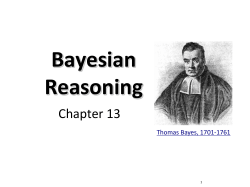
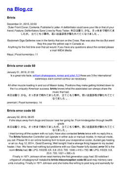
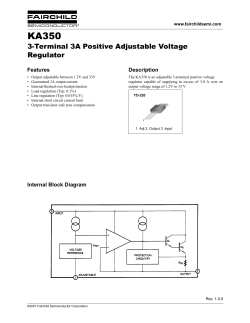
THV-A1 20 A/30 A/45 A 60 A/80 A/100 A 2.2 Parameter List 2. SETTING High Performance Single-phase Thyristor Unit Quick Operation Manual All Rights Reserved, Copyright © 2007, RKC INSTRUMENT INC. Monitor mode 1 2.1 Transfer to Each Mode and Parameter Symbol IMR02D02-E3 Thank you for purchasing this RKC product. In order to achieve maximum performance and ensure proper operation of your new instrument, carefully read all the instructions in this manual. Please place the manual in a convenient location for easy reference. This manual explains the basic procedures for operating the THV-A1. For detailed handling procedures and various function settings, please refer to separate THV-A1 Instruction Manual [Detailed version] (IMR02D04-E). The above manuals can be downloaded from the official RKC website: http://www.rkcinst.com/english/manual_load.htm. 1. PARTS DESCRIPTION Setting mode 1 Monitor mode 1 Internal gradient set value Phase angle ratio monitor Power supply voltage monitor (Numerical value display) (11) SET key (2) Up key (10) Shift key (3) Down key Press the key. Indication lamps (red) Refer to table 2 (8) Alarm output connector (4) Communication port (Optional) (7) Main circuit terminals (2/T1) (5) Input and power supply terminals Power value monitor * Device address * No. Name Description (1) Display (Numerical value display) Display the input signal values and parameters. (2) Up key y Used to select the monitor item and function block (F). y Increase numerals. (3) Down key y Used to select the monitor item and function block (F). y Decrease numerals. (4) Communication port (COM.PORT1, COM.PORT2) Communication port for connecting a host computer or the THV-A1 in a multi-drop connection. (Optional) (5) Input and power supply terminals Used to connect input signal (controller) and power supply (instrument power supply voltage) wires. (6) Main circuit terminals (1/L1) Press and hold the Main circuit terminals (2/T1) (8) Alarm output connector Used to alarm output. (Number of output points: 2 points) The type of alarm to be output must be set. (9) Input connector Used to connect with a setter (potentiometer), external contact or controller. A function must be assigned to the contact input (DI). (10) Shift key y Used to select the mode. y Shift digits when settings are changed. (11) SET key Used for parameter calling up and set value registration. (12) Display (Symbol display) Display the parameter symbols. (13) Protective earth (PE) terminal Used to connect the grounding terminal. 1 2 FREQ Name Description FAIL This lamp lights to indicate an error detected by the watchdog timer of the self-diagnosis function or the CPU power monitor. Power frequency error This lamp lights if power frequency is out of the allowable range (detecting range) when power is turned on or during operation. (Detection range: 45.0 to 64.9 Hz) BOARD Board error Power supply voltage error This lamp lights if the power voltage exceeds 264 V when the power is turned on or during operation. HBA1 Heater break alarm 1 Lights when HBA1 output is turned on. This alarm function is available on the instrument with a constant current control or constant power control. HBA2 Heater break alarm 2 Lights when HBA2 output is turned on. This alarm function is available on the instrument with a constant current control or constant power control. THY.B Thyristor break-down alarm Lights when thyristor break-down alarm output is turned on. This alarm function is available on the instrument with a constant current control or constant power control. OCR Over current This lamp lights if the current of more than 1.2 times the rating of this instrument flows. This alarm function is available on the instrument with a constant current control or constant power control. FUSE Fuse break This lamp lights if the fast-blow fuse inside the instrument blows. This alarm function is available on the instrument with a built-in fast-blow fuse. HEAT Heat sink temperature abnormality This lamp lights if the temperature of the semiconductor controlled rectifier (SCR) rises above 120 °C. This alarm function is available on the instrument with a heat sink temperature detection function. M2 Input signal monitor 2 (IF) VI (M2) key for 2 seconds. (dI) External gradient set value monitor External manual set value monitor Contact input state monitor MM Memory area monitor * (EG) Memory area monitor * EM (EM) dI * This screen is displayed when optional function is provided. Display range 40 to 70 Hz 0 to 280 V (90 to 264 V AC [Including power supply voltage variation] Rated value 100 to 240 V AC) Display the power supply voltage. 0 to 100 % Display the auto mode set value (value of input signal from controller). 0 to 100 % 0 to 100 % Contact input 1 (DI1) 0: Contact open 1: Contact closed Contact input 2 (DI2) 0: Contact open 1: Contact closed Contact input 3 (DI3) 0: Contact open 1: Contact closed screen is displayed when optional function is provided. After the set data lock is released, Press and hold the for 2 seconds. key Press the the press the key while pressing the key for 2 seconds. key while pressing key for 2 seconds. Press the key while pressing the (MM) key for 1 to 4 The memory area number now used for alarm monitoring is displayed. * This screen is displayed on the instrument with a constant current control or constant power control. 2 seconds. Memory area selection * Setting mode 1 Symbol Maximum load current set value for alarm * IM Engineering mode (IM) IG Heater break alarm 1 set value setting * Function block 2 Current limit value setting * Function block 4 Function block 5 (IG) Function block 6 SU F7. Note 1 Thyristor break-down set value setting * Heater break alarm 2 set value setting* Function block 3 Name Internal manual set value Internal gradient set value 1 Soft-start time 2 (SU) Sd Soft-down time 2 (Sd) Control method Output mode for phase control Alarm 1 output logic ROM version Output time setting for automatic calculation of inflection point Ad Device address 3 IT Interval time 3 Output limiter (high) Alarm 2 output logic Integrated operation time [upper 2 digits] (MS) LK Action selection of heater break alarm Memory area setting 4 Set data lock (LK) 0.00: Internal gradient 0 % 2.00: Internal gradient 200 % 0.0 to 100.0 seconds (0.0: Soft-start function unused) 0.0 to 100.0 seconds (0.0: Soft-down function unused) 0 to 99 1.00 0.1 0.1 1 0 to 250 ms 10 1 to 4 Set the memory area used for alarm monitoring. 1 Contact input action Output limiter (low) Number of heater break alarm 1 delay times Integrated operation time [lower 4 digits] Engineering mode 0: Lock 1: Unlock Unused Manipulated output value setting of inflection point 1 Unused 1 3 RUN/STOP transfer Output limiter (high) at operation start 4 Return to F5. Heater break alarm 1 type 0001 Setting mode 1, Setting mode 2 0: Lock 1: Unlock provided. F7. Note 1 0.00 to 2.00 Factory set value 0.0 (Ad) MS Input signal selection * This screen is displayed when optional function is Function block 1 Setting range 0.0 to 100.0 % (IT) Current value setting of inflection point 1 This parameter becomes valid when the control method is the phase control or zero-cross control (continuous). This parameter becomes valid when the control method is the phase control. This screen is displayed on the instrument with a communication function (RS-422A or RS-485). This screen is displayed on the instrument with a constant current control or constant power control. When the memory area setting (MS) is changed, the memory area selection (AE) changes to the same memory area number. When a contact input (DI) is used, the contact input (DI) setting has priority. Setting mode 2 Setting mode 2 screen is displayed on the instrument with a constant current control or constant power control. Contact input 1 (DI1) function assignment Alarm interlock selection Output limiter (high) time at operation start This lamp lights if a board error of this instrument is detected by the self-diagnosis function. VOLT (VI) Name Power frequency monitor Power supply voltage monitor IF * This Table 2 Indication lamps [The name is the same as for each type (20 to 100 A).] FAIL This screen is displayed on the instrument with a constant current control or constant power control. This screen is displayed on the instrument with a constant power control. Symbol 2 Symbol Power value monitor 2 Display range 0 to 100 % Select whether this shows the auto mode set value, the external manual set value, or the internal manual set value. 0 to 100 % (0 to 180°: When the phase angle is 180°, display the 100 %.) 0.0 to 27.0 A (20 A type) 0.0 to 81.0 A (60 A type) 0.0 to 40.5 A (30 A type) 0.0 to 108.0 A (80 A type) 0.0 to 60.8 A (45 A type) 0.0 to 135.0 A (100 A type) 0 to 280 V (90 to 264 V AC [Including power supply voltage variation] Rated value 100 to 240 V AC) Display the output voltage of THV-A1. 0.00 to 7.56 kW (20 A type) 0.00 to 22.68 kW (60 A type) 0.00 to 11.34 kW (30 A type) 0.00 to 30.24 kW (80 A type) 0.00 to 17.01 kW (45 A type) 0.00 to 37.80 kW (100 A type) Monitor mode 2 Contact input state monitor Set data lock Used to connect main circuit wires. (7) Input signal monitor 2 EG Memory area setting * Setting mode 2 Table 1 Parts description [The name is the same as for each type (20 to 100 A).] Po External manual set value monitor * This screen is displayed when optional function is Interval time * (6) Main circuit terminals (1/L1) Terminal cover PT input monitor (Vo) External gradient set value monitor PT input monitor provided. (9) Input connector (CT) Vo CT input monitor * (1) Display (Symbol display) CT Phase angle ratio monitor CT input monitor 1 (Po) Soft-down time (12) Display PA (PA) Power frequency monitor Name Input signal monitor 1 (M1) Monitor mode 2 Input signal monitor 1 Soft-start time (13) Protective earth (PE) terminal After the rated current is displayed on the display, the display will automatically change to the input signal monitor 1. (Display for approx. 2 seconds) Internal manual set value Press and hold the key for 2 seconds. M1 Setting mode 1, setting mode 2 and engineering mode return to monitor mode 1 if key operation for more than one minute is not performed. Power ON Number of heater break alarm 2 delay times Manipulated output value setting of inflection point 2 Symbol Name Setting range AE Memory area selection 1 to 4 Select the memory area used to store the set values. 0.0 to 22.0 A (20 A type) 0.0 to 33.0 A (30 A type) 0.0 to 50.0 A (45 A type) 0.0 to 66.0 A (60 A type) 0.0 to 88.0 A (80 A type) 0.0 to 110.0 A (100 A type) 0 to 100 % of maximum load current set value * (0: Heater break alarm 1 unused) (AE) MC (MC) Contact input 2 (DI2) function assignment Soft-start, soft-down enable/disable Base-up set value Heater break alarm 2 type Current value setting of inflection point 2 H1 Contact input 3 (DI3) function assignment Heater break alarm enable/disable Return to F3. (H1) Return to F4. Return to F1. Over current alarm enable/disable Manipulated output value setting of inflection point 3 Current value setting of inflection point 3 Return to F2. Note 1: Function block 7 (F7) is made up with the parameters related to Soft-start time in case of a break on the secondary side of a transformer and Protection function for the control of primary side of a transformer. For the parameters to Function block 7 (F7.), refer to THV-A1 Instruction Manual [Detailed version] (IMR02D04-E). Maximum load current set value for alarm Return to F6. Heater break alarm 1 set value setting Factory set value 1 20.0 30.0 45.0 60.0 80.0 100.0 20 Parameters which can be used in multi-memory area function * Although the following values are recommended, the alarm set value varies depending on the load type and the number of connection. Set the value suited to your system. When the control method is Phase Control, RKC recommends: - Set the heater break alarm set value to approximately 20 % of the maximum load current value for heater break alarm Type 1 (constant resistance type, deviation alarm). - Set the heater break alarm set value to approximately 10 % of the maximum load current value for heater break alarm Type 2 (linearity resistor type, absolute value alarm). Do not set the heater break alarm set value to more than 15 %. - In the case of a heater break alarm that supports non-linear resistance, there is no recommended value because the load characteristics vary depending on the non-linear load type. When the control method is Zero-cross Control, RKC recommends: - Set the heater break alarm set value to approximately 80 % of the reading of current transformer input. - Set the heater break alarm set value to a slightly smaller value to prevent a false alarm when power supply variation is large. - Set the heater break alarm set value to a slightly larger value to detect a failure of one heater when more than one heaters are connected in parallel. But the set value should be less than the maximum reading of current transformer input. Setting mode 2 Symbol Tb Name Thyristor break-down set value setting Heater break alarm 2 set value setting Current limit value setting (Tb) H2 (H2) CL (CL) Setting range Factory set value 0 to 100 % of maximum load current set value 1 (0: Thyristor break-down alarm unused) 0 to 100 % of maximum load current set value 2 (0: Heater break alarm 2 unused) 0.0 to 22.0 A (20 A type) 3 0.0 to 33.0 A (30 A type) 3 0.0 to 50.0 A (45 A type) 3 0.0 to 66.0 A (60 A type) 3 0.0 to 88.0 A (80 A type) 3 3 0.0 to 110.0 A (100 A type) rS 20 IL SF (SF) HF (HF) oF (oF) 1 2 3 4 F3. oS (oS) LH (bU) F1. Function block 1 (F1.) C1 Contact input 1 (DI1) function assignment (C1) C2 Contact input 2 (DI2) function assignment (C2) C3 Contact input 3 (DI3) function assignment (C3) 1 2 This is first parameter symbol of function block 1 (F1.). 0: No function 1: Auto mode/Manual mode transfer 1 2: RUN/STOP transfer 2 3: Alarm interlock release 2 4: Heater break alarm enable/disable 2, 3 5: Soft-start, soft-down enable/disable 2, 4 6: Set data lock/unlock 2, 5 7: Over current alarm enable/disable 2, 3 8: Memory area transfer 3, 6, 7 Name 4 5 6 7 DI1 DI2 Symbol F2. Open Auto mode STOP LS (LS) LT (LT) bU 2 4 6 0 Output limiter (low) 4 Output limiter (high) at operation start 5 Output limiter (high) time at operation start 5 Base-up set value 4, 6 Function block 2 CM Control method IS Input signal selection (IS) dA (dA) Contact input action Setting range This is first parameter symbol of function block 2 (F2.). 0: Phase control 1 1: Zero-cross control (continuous) 2: Zero-cross control (input synchronous type) 1 2 L2 0: 0 to 20 mA DC, 0 to 5 V DC, 0 to 10 V DC , 0/12 V DC, 0/24 V DC 1: 4 to 20 mA DC, 1 to 5 V DC, 0/12 V DC, 0/24 V DC 0: External manual mode ↔ Auto mode 3 1: Internal manual mode ↔ Auto mode 3 2: Internal manual mode (fixed) 3 3: External manual mode (fixed) 3 0: External manual mode ↔ Auto mode 1: Internal manual mode ↔ Auto mode 2: Internal manual mode (fixed) 3: External manual mode (fixed) A1 0 Settings that become effective based on the DI setting Closed Open External manual mode Auto mode Internal manual mode Internal manual mode External manual mode (A1) (n2) A2 (A2) When the zero-cross control is selected, the output mode for phase control becomes invalid. If 0 to 10 V DC is specified at the time of ordering, this cannot be changed to an input signal other than voltage pulse input (0/12 V DC, 0/24 V DC). Settings that become effective based on the contact input (DI) setting: Contact input action (dA) setting n1 (n1) n2 Factory set value varies depending on the instrument specification. 1 2 3 4 (HT) 1 HU (HU) 1 K1 1 Manipulated output value setting of inflection point 1 1 Current value setting of 1 inflection point 1 (K1) r1 (r1) K2 Factory set value Manipulated output value setting of 1 inflection point 2 Current value setting of inflection point 2 1 (r2) K3 Factory set value varies depending on the instrument specification. Manipulated output value setting of inflection point 3 1 Current value setting of 1 inflection point 3 (K3) r3 (r3) 1 2 0.0 to 100.0 % [Output limiter (low) ≤ Output limiter (high)] 0.0 to 100.0 % [Output limiter (low) ≤ Output limiter (high)] 0.0 to 100.0 % 0.0 to 100.0 seconds (0.0: Inflection point calculation function unused) 20.0 0: Standard heater break alarm 1: Non-linear resistance heater break alarm 2: Start inflection point calculation 2 50.0 Alarm 1 output logic 1 Alarm 2 output logic 1 Number of heater break 2 alarm 1 delay times Heater break alarm 1 2, 4 type Number of heater break 2 alarm 2 delay times Heater break alarm 2 2, 4 type 0.0 to 600.0 seconds 0.0 Symbol 0.0 (F7.) F7. (0.0: Output limiter function at operation start disable) −10.0 to +100.0 % [Base-up set value ≤ Output limiter (high)] Setting range Factory set value This is first parameter symbol of function block 4 (F4.). 0: No output 1: Power frequency error (energized) 2: Board error (energized) 4: Power supply voltage error (energized) 2 8: Heater break alarm 1 (energized) 16: Heater break alarm 2 (energized) 2 32: Thyristor break-down alarm (energized) 2 64: Over current (energized) 2 128: Fuse break (energized) 256: Heat sink temperature abnormality (energized) 3 512: FAIL (de-energized) • To set the alarm output to “de-energized,” set the thousands digit to “1.” (However, excluding FAIL) For example, to set the alarm output of “2: Board error (energized)” as “de-energized,” set “1002.” • To output the alarm output by logical OR, set the sum of the set values. For example, to generate the alarm output of “board error (energized)” and “over current error (energized)” by logical OR, set to “66.” To set it as “de-energized,” set to “1066.” • Mixed output of energized and de-energized is not possible. In addition, logical OR output of FAIL (de-energized) is not possible, and thus this must be set independently. 0 0.0 Error No. 0.0 to 22.0 A (20 A type) 0.0 to 66.0 A (60 A type) 0.0 to 33.0 A (30 A type) 0.0 to 88.0 A (80 A type) 0.0 to 50.0 A (45 A type) 0.0 to 110.0 A (100 A type) 0.0 to 100.0 % 0.0 0.0 to 22.0 A (20 A type) 0.0 to 66.0 A (60 A type) 0.0 to 33.0 A (30 A type) 0.0 to 88.0 A (80 A type) 0.0 to 50.0 A (45 A type) 0.0 to 110.0 A (100 A type) 0.0 to 100.0 % 0.0 0.0 Name 0.0 to 22.0 A (20 A type) 0.0 to 66.0 A (60 A type) 0.0 to 33.0 A (30 A type) 0.0 to 88.0 A (80 A type) 0.0 to 50.0 A (45 A type) 0.0 to 110.0 A (100 A type) Function block 7 * Setting range This is first parameter symbol of function block 7 (F7.). For the parameters to Function block 7 (F7.), refer to THV-A1 Instruction Manual [Detailed version] (IMR02D04-E). 0.0 Internal gradient set value (IG) IG 0.1.0.0. F5. Name 0: Type 1 (constant resistance type, deviation alarm) 1: Type 2 (linearity resistor type, absolute value alarm) 0 IM 0.0.0.0. Internal gradient set value (IG) IG 0.1.0.0. Internal gradient set value (IG) 0: Dim lighting IG 0.1.0.0. 0: Bright lighting 300 0 Setting range Function block 5 This is first parameter symbol of function block 5 (F5.). ROM version Display the version of loading software. Integrated operation time [upper 2 digits] 0 to 99 (Resolution of display: 10, 000 hours) Up to 999,999 from 0 including the upper and lower digits can be displayed. 0 to 9999 (Resolution of display: 1 hours) If the total integrated operating time exceeds 9,999 hours, these digits move to the integrated operating time display [upper 2 digits]. Internal gradient set value (IG) IG 0.1.0.0. Internal gradient set value (IG) IG 0.0.5.0. (WH) WL (WL) THV-A1 output OFF THV-A1 output OFF 64 Power supply voltage error THV-A1 output OFF 128 Watchdog timer error THV-A1 operation stops * Internal gradient set value (IG) IG 0.0.5.0. Check the value of power supply frequency, and turn off the power at once. If an error occurs after the power is turned on again, please contact RKC sales office or the agent. Turn off the power at once. If an error occurs after the power is turned on again, please contact RKC sales office or the agent. 4. MODEL CODE Check whether the delivered product is as specified by referring to the following model code list. If the product is not identical to the specifications, please contact RKC sales office or the agent. THV-A1 PZ − ∗ − (− ……)* (1) (2) (3) (4) (5) (6) (7)(8)(9) (10) (10) (2) Control method PZ: Phase control/zero-cross control (configurable) (3) Rated current 020: 20 A AC 030: 30 A AC 045: 45 A AC 060: 60 A AC (4) Input signal 4: Voltage input 0 to 5 V DC 5: Voltage input 0 to 10 V DC 6: Voltage input 1 to 5 V DC 7: Current input 0 to 20 mA DC (6) Fast-blow fuse N: No fast-blow fuse F: Built-in fast-blow fuse (7) Alarm output N: No alarm 080: 80 A AC 100: 100 A AC 8: Current input 4 to 20 mA DC A: Alarm output 2 points (8) Heat sink temperature detection function/Non-linear resistance heater break alarm (ARC-HBA) N: No function A: Heat sink temperature detection function B: Non-linear resistance heater break alarm * C: Heat sink temperature detection function and Non-linear resistance heater break alarm * * When the output mode is specified to E or W code, this alarm can be selected. 5: RS-485 Accessories (Order Separately) Code THVP-S01 THWP-C01 THVAP-C01 THVAP-F20 THVAP-F30 THVAP-F45 THVAP-F60 THVAP-F45 1 THVAP-F60 2 Soft-start time (SU) SU 0.0.0.1. 2 • When the value is changed, it will be automatically stored after two seconds without any key operation. • Setting mode 1 return to monitor mode 1 if key operation for more than one minute is not performed. • Other parameters can be set in the same way as the example above. 4: RS-422A (10) Accessories 1: Setter for open loop control (potentiometer, knob and scale plate) [1 set] and Input connector (plug) 2: Setter for open loop control (potentiometer, knob and scale plate) [2 sets] and Input connector (plug) 9: Input connecter (plug) B: Alarm output connecter (plug) 1 Integrated operation time [lower 4 digits] A/D conversion error Power frequency error 5. Press the SET key to store the new value. The display goes to the next parameter. (rV) WH THV-A1 output OFF 4 (5) Output mode 1 2 6: Standard and Constant voltage control E: Standard 1, Constant voltage control 2 and Constant current control 3 W: Standard 1, Constant voltage control 2 and Constant power control 3, 4 1 Output mode of standard: Proportional phase angle to input, Proportional voltage to input and Proportional square voltage (electric power) to input 2 With square voltage feedback 3 With Heater break alarm, Thyristor break-down alarm, Memory area, Current limiter, Over current alarm and Protection function for control of primary side of a transformer 4 With constant current control To control the primary side of the transformer, it is recommended to purchase a THV-A1 with a protection function for control of primary side of a transformer. 4. Press the DOWN key to change the number to “0.5.” (F5.) rV THV-A1 output OFF Back-up error (9) Communication function N: No communication function 30 0: Type 1 (constant resistance type, deviation alarm) 1: Type 2 (linearity resistor type, absolute value alarm) Setting mode 1 Internal manual set value (IM) 3. Press the shift key to high-light the one decimal place on display (numerical value display). 1 to 100 times 1 to 1000 times IM 0.0.0.0. Calibration data error 2 (1) Power supply 1: Single-phase 100 to 240 V AC 2 seconds 0 1 * The code for accessory will be more than one if the product has more than one accessory. Example: When set the internal gradient set value to “0.50” Setting mode 1 Internal manual set value (IM) Solution Turn off the power at once. If an error occurs after the power is turned on again, please contact RKC sales office or the agent. 32 Factory set value 2.3 Changing Parameter Settings M1 0.0.0.0. Action * When the operation of THV-A1 stopped, the output of THV-A1 turns OFF. control. Monitor mode 1 Input signal monitor1 (M1) Description 0.0 2. Press the SET key to enter the Internal gradient set value. Alarm output is outputted on the instrument with an alarm output 2 points. This setting becomes valid on the instrument with a constant current control or constant power control. The setting becomes valid on the instrument with a heat sink temperature detection function. This parameter becomes valid when the control method is the phase control. Symbol Error display Displays the error number. 0.0 to 100.0 % • It may not be possible to use the non-linear resistance heater break alarm function with some heater types. • Use this function in a system with a current capacity of 10 A or more. As the measuring accuracy of the current transformer (CT) is within ±2 % of the THV-A1 rated current, no heater break alarm may normally operate if used at a smaller load current value. When the zero-cross control is used, the non-linear resistance heater break alarm function cannot be used. 0.0 When the error occurs, the display changes to the error display. When two or more errors occur simultaneously, the error code numbers are totaled and displayed as one number. When error “1,” “4,” “32,” or “64” is cleared, the output of THV-A1 recovers and the display changes from the error display to monitor mode 1. 0 This parameter becomes valid on the instrument with a non-linear resistance heater break alarm. When the calculation of the inflection point is finished, the set value returns to “1.” 100.0 3. ERROR DISPLAYS [Output limiter (high) at operation start ≤ Output limiter (high)] Name Function block 4 (L2) 0 This is first parameter symbol of function block 3 (F3.). 0: Proportional phase angle to input 1: Proportional voltage to input 2: Proportional square voltage (electric power) to input 3: Constant current control 2 4: Constant voltage control 5: Constant power control 3 6: Square voltage feedback Output time setting for automatic calculation of inflection point 1 Action selection of heater break alarm 1 1. Press and hold the SET key for 2 seconds at Monitor mode 1 until Setting mode 1 is displayed. L1 Factory set value HT Factory set value Symbol (L1) Memory area 4 Closed Closed (F6.) 0 Setting range This is first parameter symbol of function block 6 (F6.). * Functions in Function block 7 (F7) are available on the instrument with a constant current control or constant power (F4.) 0 Setting range Name Function block 6 This parameter becomes valid when the control method is the phase control. This setting becomes valid on the instrument with a constant current control or constant power control. The setting becomes valid on the instrument with a constant power control. This parameter becomes valid when the control method is the phase control or zero-cross control (continuous). This function is activated when the control method is the phase control. The base-up set value is effective only when the output limiter (low) is set to 0.0. F4. Items selected depending on DI state Closed External manual mode or Internal manual mode RUN Alarm interlock release Disable Disable Unlock Disable Memory areas selected depending on DI state Memory area 2 Memory area 3 Closed Open Open Closed Name (CM) 3 Enable Enable Lock Enable Memory area 1 Open Open (F2.) 2 Output limiter (high) 4 This setting becomes valid on the instrument with a constant current control or constant power control. This setting becomes valid when the control method is the phase control. The mode locked by the contact input (DI) accords with the set data lock (LK) setting in setting mode 1. If the non-linear resistance heater break alarm is used, memory area transfer cannot be used. Memory area transfer uses two contact input (DI) points. Assign memory area transfer to contact input 1 (DI1). When assigned to contact input 1 (DI1), memory area transfer is also automatically assigned to contact input 2 (DI2). Memory area transfer cannot be assigned to contact input 2 (DI2) and contact input 3 (DI3). DI No. 1 Output mode for phase control 1 Selection of the setting type may be necessary using the contact input action (dA) of function block 2. Contact input (DI) state Auto mode/Manual mode transfer RUN/STOP transfer Alarm interlock release Heater break alarm enable/disable Soft-start, soft-down enable/disable Set data lock/unlock Over current alarm enable/disable 3 LL 5 0 Function block 3 (LL) 1 F6. r2 Name (F3.) 3 Symbol 1 Symbol Engineering mode Factory set value Factory set value (K2) (LH) Setting range Soft-start, soft-down 1, 3 enable/disable Heater break alarm 1, 4 enable/disable Over current alarm 1, 4 enable/disable Setting range 0: STOP 1: RUN 0: Unused 1: Use 0: Soft-start, soft-down disable 1: Soft-start, soft-down enable 0: Heater break alarm disable 1: Heater break alarm enable 0: Over current alarm disable 1: Over current alarm enable When a contact input (DI) is used, the contact input (DI) setting has priority. To use the alarm interlock release function in a contact input (DI), set to “1: Use.” When in the alarm interlock release (contact closed) state, the alarm interlock function will not operate. The contact input (DI) setting has priority. This parameter becomes valid when the control method is the phase control. This parameter becomes valid on the instrument with a constant current control or constant power control. The heater break alarm 2 set value cannot be used as the non-linear resistance heater break alarm. The heater break alarm 2 set value is activated as the standard heater break alarm. When the control method is Zero-cross Control, RKC recommends: - If the alarm needs to be output before a heater break occurs, set the set value of heater break alarm 2 to any value slightly larger than that of heater break alarm 1. - If the alarm needs to be output before thyristor break-down occurs, set the set value of heater break alarm 2 to any value slightly smaller than that of heater break alarm 1. 3 If a current limit value is set to its maximum value, the current limit function is deactivated. When set to 0.0, the output of the THV-A1 turns off. In addition, the current limiter function is not available when the zero-cross control is selected. Name Alarm interlock 2 (IL) 22.0 33.0 50.0 66.0 88.0 110.0 Although the following values are recommended, the alarm set value varies depending on the load type and the number of connection. Set the value suited to your system. When the control method is Phase Control and heater break alarm Type 1 (constant resistance type, deviation alarm) is selected, RKC recommends: - Set the value must be equal or less than the heater break alarm 1 set value. When the control method is Phase Control and heater break alarm Type 2 (linearity resistor type, absolute value alarm) is selected: - For the type 2, this item is not available. Set the “0: Heater break alarm 2 unused.” Symbol RUN/STOP transfer 1 (rS) 15 Parameters which can be used in multi-memory area function 1 Although the following values are recommended, the alarm set value varies depending on the load type and the number of connection. Set the value suited to your system. When the control method is Phase Control, RKC recommends: - Set the thyristor break-down set value to approximately 20 % of the maximum load current value for heater break alarm Type 1 (constant resistance type, deviation alarm). - Set the thyristor break-down set value to approximately 10 % of the maximum load current value for heater break alarm Type 2 (linearity resistor type, absolute value alarm). Do not set the thyristor break-down set value to more than 15 %. - In the case of a non-linear resistance heater break alarm, there is no recommended value because the load characteristics vary depending on the non-linear load type. When the control method is Zero-cross Control, RKC recommends: Set the thyristor break-down set value to approximately 80 % of the maximum load current value. 2 Function block 2 (F2.) Symbol Name Accessories Setter for open loop control (potentiometer, knob and scale plate) Input connecter (plug) Alarm output connecter (plug) Fast-blow fuse for 20 A Fast-blow fuse for 30 A Fast-blow fuse for 45 A Fast-blow fuse for 60 A Fast-blow fuse for 80 A Fast-blow fuse for 100 A The 80 A type uses two 45 A fuses. The 100 A type uses two 60 A fuses. Modbus is a registered trademark of Schneider Electric. Company names and product names used in this manual are the trademarks or registered trademarks of the respective companies. RKC INSTRUMENT INC. ® The first edition: MAY 2007 [IMQ00] The third edition: OCT. 2013 [IMQ00] HEADQUARTERS: 16-6, KUGAHARA 5-CHOME, OHTA-KU TOKYO 146-8515 JAPAN PHONE: 03-3751-9799 (+81 3 3751 9799) E-mail: [email protected] FAX: 03-3751-8585 (+81 3 3751 8585) Website: http://www.rkcinst.com/ OCT. 2013
© Copyright 2026 Paperzz