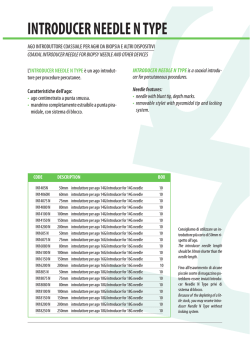
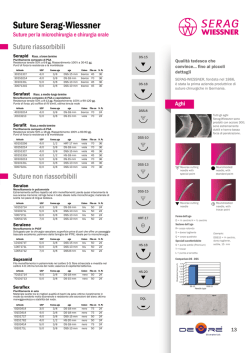
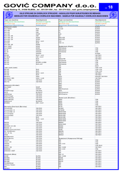
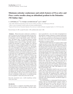
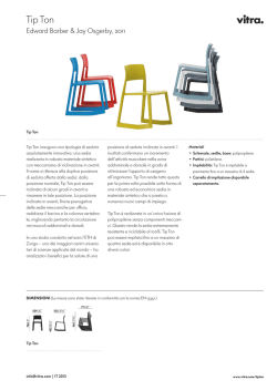
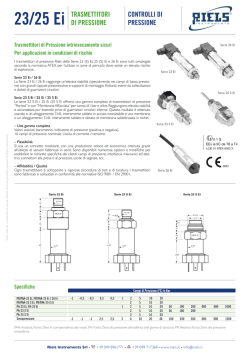
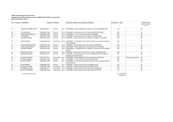
Virtually-tracked Interventional Procedures Under US Guidance: Preliminary Evaluation E. Fabbro*; G. Turtulici**; G. Ferrero*; C. Martini*; A. Corazza*; F. Nosenzo*; E. Silvestri** * Scuola di Specializzazione in Radiodiagnostica, Università degli Studi di Genova ** S.C. di Radiologia Diagnostica e Interventistica ,Ospedale Evangelico Internazionale, Genova BACKGROUND A large number of interventional procedures can be made with a percutaneous approach. The relatively recent advances in ultrasound (US) technologies and its large availability made US guidance competitive, if not superior in some cases, with other imaging techniques such as CT, MRI or fluoroscopy. The most common sites of such procedures include the liver, pancreas, kidney and pelvis, breast, thyroid and soft tissues. In some cases, the region of intervention can present some anatomical limitations affecting the US approach that can be used to reach the target and consequently the US visualization of the needle, which remains the most challenging and difficult aspect of such US-guided procedures. Recently, an electromagnetic-tracked system revealing the position of the needle according to a small sensor embedded in its tip (“needle tracking”) was presented, with good results. PURPOSE The purpose of our work is to evaluate accuracy, safety, and potential uses of a new needle tracking system when performing US-guided percutaneous procedures that is applicable to commercially available needles. MATERIALS AND METHODS An ultrasound machine (LOGIQ E9, GE Healthcare, Chalfont St Giles, UK) coupled with a low magnetic field generator was used. Two electromagnetic position sensors connected with a position sensing unit (PSU) were attached on the probe (2,8-5 MHz curvilinear C1-5 or 4-13 MHz linear ML-6-15, GE) through a bracket, and one similar sensor was placed on the needle through a disposable device (VirtuTRAX, CIVCO) and connected to the PSU. A low magnetic field generator (on the left) transmitting the electromagnetic signal is connected to the PSU (on the right) and maintained at maximum 80 cm away from the probe. Two small moveable electromagnetic sensors are attached onto the sonographic probe through a bracket. A third electromagnetic sensor (in black) is placed at the bottom of a commercially available needle through a disposable device. MATERIALS AND METHODS The needle tip position is calculated by the system according to the mutual position of the probe and the needle shaft, and of the length of the needle that is set in advance by the operator. Thus, the expected needle path is graphically superimposed on the B-mode image with a line in different colors according to its orientation with the imaging plane. When the expected needle path fully lies in the imaging plane (in-plane approach), a green line appears on the B-mode scan according to the angulation and advancement of the needle, and its tip is located with a green cross. The path that needle has traveled is represented with a dashed line, while the prospective needle path is dotted. MATERIALS AND METHODS When the needle is inserted with an out-of plane approach, the virtual path is projected and represented in red or blue, and the location where the needle will intersect the image plane is displayed in real time as a green circle. The projection of the needle tip on the US scan plane is marked as a square, which gets smaller as the needle approaches the US scan plane. When the needle tip reaches the scanning plane, the square and green circle become a green cross. Before the procedure, the patient’s imaging files were studied to localize the target lesion and to correctly plan the approach to be used. Out-of-plane approach. The needle lies in another scanning plane, its tip is graphically projected and displayed as a square. Out-of-plane approach. As the needle crosses the imaging plane, the square and the green circle become a green cross. MATERIALS AND METHODS Twenty-four percutaneous virtually-tracked US-guided fine-needle-aspirations on thyroid (n=8), breast (n=8) and liver (n=8) nodules (mean diameter: 20 mm; range: 10-40 mm, mean depth: 40 mm; range: 15-75 mm) were made, using conventional 16G to 22G needles with an out-plane approach. For each procedure we evaluated: technical success, diagnostic success, distance between needle tip position and its virtual display, number of needle redirections, procedure time and complications. All the procedures were made by two experienced radiologists in the field of US-guided percutaneous procedures. Institutional review board approval and patients’ informed consent were obtained. • Technical success was considered positive when the needle tip could be sonographically demonstrated at least in another scanning plane. • Insufficent sampling was considered when pathologist considered insufficient the amount of tissue received. • Diagnostic success was considered when pathology confirmed a malignant lesion (“true positive”) or when a benign lesion at pathology results could be demonstrated at follow-ups (“true negative”). • Diagnostic insuccess was considered in case of benign pathological result with malignant diagnosis at followup (“false negative”). • False positive results were not observed. RESULTS • • • • • • In all 24 cases, the needle tip correctly reached the target lesion, without the need to change the approach and reinsert the needle. In 6/24 patients (25%) some redirections were needed to correct the needle placement, without the need to repuncture the skin. Overall diagnostic success, considered as true positives plus true negatives, was obtained in 22/24 samples (91,7%). False negative and false positive results were not observed. Insufficient samples for pathological analysis were obtained in 2/24 cases (8,3%). The median procedure time was 30 s (10-60s). In 3/8 procedures using a 22G needle, we noticed a slight gap (5 mm) between the virtual and the real needle tip position. It was not observed a significant gap when thicker needles were used, such as 16G, 18G or 20G. Lesion size, depth and localization did not affect significantly the technical or diagnostic success of the procedure. No complications were observed. RESULTS Out-of-plane approach to a breast nodular lesion. The green cross indicates that the needle has just entered the target. The past and prospected trajectories are projected on the screen. Out-of-plane approach to a nodular lesion of the liver. The deep location of the lesion required the needle to be inserted with a very acute angle compared to the US beam (about 20-30 degrees ). DISCUSSION The basic principle about needle visualization performing US percutaneous procedures is that the reflectivity of a tissue is related to the acoustic impedance and the size of the structure, in comparison with the wavelength of the incident beam. Artificial objects, such as a needle with its smooth surface, act as specular reflectors when they lie in the US scan plane and can be easily visualized when the incident beam is perpendicular to their surface, reflecting at the maximum level the US echoes (in-plane approach). The in-plane approach can be used when the target lesion lies in a superficial location and the anatomical region allows the lateral insertion of the needle with a free-hand technique, offering the visualization of the whole needle portion under the US beam. However, it does require considerable practice and experience to master the twohanded coordination necessary for needle visualization and lesion targeting and to predict in advance the correct angle when starting to insert the needle in the skin. As the angle of incidence diminishes, a minor amount of echoes is reflected and the needle becomes visible poorer, until at angles inferior to 60° its direct visualization is not possible. IN-PLANE APPROACH DISCUSSION When the depth of the target lesion increases, the use of a needle guiding kit can be needed to plan the correct insertion of the needle at a fixed angle, at a fixed distance relative to the transducer and in the US scan plane, thus limiting the positioning of the probe and the selection of the site of needle insertion. In some cases, for example at greater depths or when the lesion has to be reached with the shortest path, the needle can be inserted parallel to the US beam (coaxial approach). With this approach, the needle tip position can only be assessed indirectly, recognizing the small movements of tissues induced by its advance and requires considerable experience COAXIAL APPROACH DISCUSSION OUT-OF-PLANE APPROACH Another US approach that can be used is the freehand out-of-plane approach. In this situation, the needle is inserted and advanced in tissues through another plane than the one of the US scan, to reach a target that lies in the scanning plane. In this way, only the needle tip is appreciable, as a hyperechoic dot crossing the scanning plane. This approach is the one selected for this study, and can be particularly difficult even for experienced operators. DISCUSSION After planning the correct orientation of the needle before entering the skin, we found essential to understand how to correctly insert and advance the needle, following a straight path to the target lesion. A correct training can be helpful in order to understand how to follow at best the projected orientation of the needle and its tip without the need of needle pulling backs and redirections. For this reason, we think that the number of redirections of the needle can decrease if a correct manuality is achieved by the operator with a short training. Technical success was achieved in 100% of cases, with the confirmation of the correct position of the needle tip in the target lesion though a different US scanning plane. It was not observed a significant gap when thick needles were used, such as 16G, 18G or 20G, also in the cases when a redirection was needed. When using 22G needles, we observed a gap between the virtual track and the real needle position of about 5 mm. This discrepancy can be due to the bending of the thin 22G needle through tissues, an effect that cannot be measured by the system since the sensor is located at the bottom of the needle. Scheme showing the relations between needle and the US beam when different approaches are used. DISCUSSION Diagnostic success achieved (91,7%) has revealed itself as comparable to reports in other published series, although our study presents a large variability due to the heterogenicity and topography of the lesions. Our results show an effective help of this tracking system when performing US-guided percutaneous procedures. The possibility to plan the most practical approach to reach the target from any angle relative to the transducer, whether in- or outof-plane, and to monitor the position and the advancing of the needle even if it does not lie in the scanning plane can be helpful in daily practice, especially for less experienced operators. Moreover, the possibility to position the needle sensor on its bottom allows for using with all commercially available needles, without the need of using expensive dedicate needles thus reducing the costs of such procedures. However, our study has some limitations such as the absence of a control group without electromagnetic guidance, the lack of less experienced operators to execute the procedure, the relatively small number of patients and the heterogeneous regions of intervention. Further studies and comparisons are needed to confirm our results on larger samples. CONCLUSIONS This new electromagnetic positioning system can help to reach with good accuracy difficult or deep targets with the most practical percutaneous approach, Target lesions can be reached even if the needle is not clearly visible (e.g. needle coaxial or out-of-plane approach), with the advantages of a free hand technique and freedom for needle placement. The possibility to position the sensor on the needle bottom allows for using all commercially available needles, without the need of using expensive dedicate needles. BIBLIOGRAPHY 1. Hakime A, Deschamps F, De Carvalho EG, Barah A, Auperin A, De Baere T. Electromagnetic-Tracked Biopsy under Ultrasound Guidance: Preliminary Results. Cardiovasc Intervent Radiol 2011 Sept. 2. Matalon T, Silver B. US guidance of interventional procedures. Radiology 1990; 174:43-47 3. Ewertsen C, Nielsen KR, Nielsen MB. Freehand biopsy guided by electromagnetic needle tracking: a phantom study. Ultraschall Med. 2011 Dec;32(6):614-8. 4. Gupta S. New techniques in image-guided percutaneous biopsy. Cardiovasc Intervent Radiol. 2004 Mar-Apr;27(2):91-104. 5. Sheafor DH, Paulson EK, Kliewer MA et al (2000) Comparison of sonographic and CT guidance techniques: does CT fluoroscopy decrease procedure time? Am J Roentgenol 174(4):939–942. 6. Howard MH, Nelson RC, Paulson EK et al (2001) An electronic device for needle placement during sonographically guided percutaneous intervention. Radiology 218(3):905–911. 7. Dodd GD III, Esola CC, Memem DS et al (1996) Sonography: the undiscovered jewel of interventional radiology. Radiographics 16:1271–1288. 8. Memel DS, Dodd GD, Esola CC (1996) Efficacy of sonography as a guidance technique for biopsy of abdominal, pelvic, and retroperitoneal lymph nodes. Am J Roentgenol 167(4):957–962. 9. Stattaus J, Kuehl H, Ladd S et al (2007) CT-guided biopsy of small liver lesions: visibility, artifacts, and corresponding diagnostic accuracy. Cardiovasc Intervent Radiol 30:928–935. 10. Cardella J, Bakal C, Bertino R, for the Society of Interventional Radiology et al (2003) Standards of Practice Committee Quality Improvement Guidelines for image-guided percutaneous biopsy in adults. J Vasc Interv Radiol 14:227–230.
© Copyright 2026 Paperzz