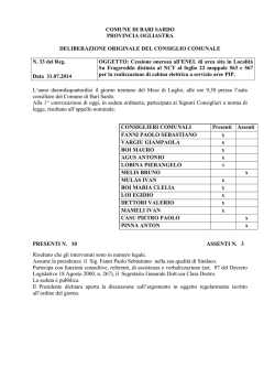
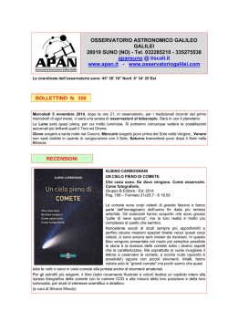
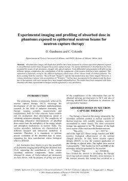
minerals
Article
Structural Characterization of Iron Meteorites
through Neutron Tomography
Stefano Caporali 1,2,†, *, Francesco Grazzi 3,† , Filomena Salvemini 3,4 , Ulf Garbe 4 ,
Steven Peetermans 5,‡ and Giovanni Pratesi 6
1
2
3
4
5
6
*
†
‡
Consorzio Interuniversitario Nazionale per la Scienza e Tecnologia di Materiali (INSTM), Firenze 50123, Italy
Dipartimento di Chimica, Università degli studi di Firenze, Sesto Fiorentino, FI 50019, Italy
Consiglio Nazionale delle Ricerche, Istituto dei Sistemi Complessi, Sesto Fiorentino, FI 50019, Italy;
[email protected] (F.G.); [email protected] (F.S.)
Bragg Insitute, Australian Nuclear Science and Technology Organisation (ANSTO), Lucas Height,
NSW 2234, Australia; [email protected]
Paul Scherrer Institut, Swiss Spallation Neutron Source (SINQ) Neutron Source, Villigen 5232, Switzerland;
[email protected]
Museo di Storia Naturale, Università degli studi di Firenze, Firenze 50123, Italy; [email protected]
Correspondence: [email protected]; Tel.: +39-055-457-3146
These authors contributed equally to this work.
Current address: AV Controlatom, Vilvoorde 1800, Belgium
Academic Editors: Jesus Martinez-Frias and Hasnaa Chennaoui
Received: 13 January 2016; Accepted: 16 February 2016; Published: 19 February 2016
Abstract: In this communication, we demonstrate the use of neutron tomography for the structural
characterization of iron meteorites. These materials prevalently consist of metallic iron with variable
nickel content. Their study and classification is traditionally based on chemical and structural
analysis. The latter requires cutting, polishing and chemical etching of large slabs of the sample
in order to determine the average width of the largest kamacite lamellae. Although this approach
is useful to infer the genetical history of these meteorites, it is not applicable to small or precious
samples. On the base of different attenuation coefficient of cold neutrons for nickel and iron, neutron
tomography allows the reconstruction of the Ni-rich (taenite) and Ni-poor (kamacite) metallic phases.
Therefore, the measure of the average width of the largest kamacite lamellae could be determined in
a non-destructive way. Furthermore, the size, shape, and spatial correlation between kamacite and
taenite crystals were obtained more efficiently and accurately than via metallographic investigation.
Keywords: iron meteorites;
non-destructive analysis
neutron imaging;
neutron tomography;
taenite;
kamacite;
1. Introduction
Iron meteorites are assumed to be the splinter portions of ancient asteroid's core that, after
extensive melting, separation of the metal from the silicate and more or less rapid crystallization,
went shattered by hypervelocity impacts. The overwhelming bulk composition of these meteorites
consists of Fe–Ni alloys; i.e., kamacite (α-(Fe,Ni), BCC structure) and taenite (γ-(Ni,Fe), FCC structure).
Minor minerals (sulphides, phosphides) may occur as accessory phases.
Traditionally, iron meteorites are classified based on their structures; i.e., the examination of the
shape and size of the kamacite lamellae formed as consequence of exsolution from the taenite phase.
The kamacite bandwidth is primarily dictated by the bulk chemical composition, i.e., nickel content,
and the cooling rate; the higher the nickel content the faster the cooling rate is, the smaller the kamacite
bandwidths are. A scheme of the structural classification is represented in Table 1.
Minerals 2016, 6, 14; doi:10.3390/min6010014
www.mdpi.com/journal/minerals
Minerals 2016, 6, 14
2 of 8
Table 1. Structural classification of iron meteorites (data from [1]).
Structural Class
Symbol
Kamacite Bandwidth (mm)
Hexahedrites
Coarsest octahedrites
Coarse octahedrites
Medium octahedrites
Fine octahedrites
Finest octahedrites
Plessitic octahedrites
Ataxites
H
Ogg
Og
Om
Of
Off
Opl
D
>50
3.3–50
1.3–3.3
0.5–1.3
0.2–0.5
<0.2
<0.2 spindles
<0.03
Even though, nowadays, the chemical classification based on Ni, Ge, Ga and Ir content is preferred
with respect to structural classification [2], the two approaches support and agree with each other.
Other than for classification purposes, the study of the meteorite micro- and macro-structure can
provide valuable information regarding the phenomena that happened after meteorite crystallization.
For instance, plastic deformation and stresses or annealing processes (reheating) caused by impact
shocks or movement of the overburden, affect the meteorite microstructure. It is well known that the
same pristine material can present different features regarding the secondary stages of metamorphism
suffered after crystallization.
Traditionally, structural data are obtained by means of metallographic investigations requiring
cutting of large parts, if not all, of the sample. That is obviously not acceptable for unique or very rare
samples. Furthermore, metallographic investigation is performed on randomly cut surfaces returning
2D images of a 3D distribution of metallic phases. Even if structural data are extracted by averaging the
bandwidths obtained from mutually perpendicular sections and correction factors for single randomly
oriented sections have been published [3,4], these methodologies invariably represent approximations
of the real 3D crystal distribution.
Computed tomography (CT) is a method to acquire volumetric maps of the beam attenuation
coefficient distribution of an object. The method has been principally developed for X-ray imaging for
probing a sample interior, but it applies to neutrons as well. It uses radiographic projection images
from many views to reconstruct the distribution of materials in the sample. Mostly, the projections are
acquired with equiangular steps over either 180˝ or 360˝ to cover the whole sample. In the last decade,
X-ray computed tomography (X-ray CT) has been successfully applied to the study of planetary
materials, such as chondrites [5–12], stardust [13,14], and tektites [15,16].
Use of neutron computed tomography (NCT) is somewhere less common since the production
of a parallel neutron beam of sufficient intensity and suitable energy range is technologically much
more complex than an X-ray beam. Beamlines suitable for neutron tomography are few and began
to appear at research facilities only in the late 1990s; thus, optimal imaging protocols are still under
development. Contrast in NCTs is generated by local differences in the neutron cross section reflecting
the elemental (and in some cases the isotopic) composition of the sample. Therefore, NCT investigations
are preferentially performed for those objects where neutrons present higher contrast or provide a
better sample penetration than conventional X-ray CT. Analogously to X-ray CT, NCT generate 3D
datasets in which the specimen is represented by an array of volume elements or voxels, each of which
is assigned a grayscale (or false color scale) that correlates with the neutron attenuation (or neutron
transmissivity). To obtain the 3D feature of the object, the measurement of neutron transmissivity
along different linear paths through the specimen are combined via a mathematical inversion process
called reconstruction.
In principle X-ray CT and NCT, can be considered two complementary techniques; NCT is
superior to X-Ray CT to study the interior of dense materials, such as large metallic items [17–20],
characterized by large and quite similar X-ray absorption coefficients, impairing the determination
of internal features. In spite of their utility to cope with problems that relate to Earth science, NCT
Minerals 2016, 6, 14
3 of 8
studies of geologic materials are few [21–23] and, to the best of our knowledge, this technique has
not been applied yet to planetary materials apart from a grain determination and phase distribution
measurement performed by the same experimental team as the Mont Dieu meteorite [24].
In this paper, we assess the suitability and usefulness of neutron computed tomography (NCT) to
characterize the structural features of five different iron meteorites. The different attenuation capability
(sum of neutron absorption and neutron scattering) of iron and nickel (see Table 2) allows to discern
within the taenite (Ni-rich) and kamacite (Ni-poor) crystals. This capability was successfully used
to reconstruct the 3D distribution, size, and shape of the kamacite lamellae. The structural data
obtained by means of NCT, in non-destructive way, fully agree with literature data obtained via
metallographic investigation.
Table 2. Neutron cross sections averaged for the natural isotopes composition for Ni and Fe [25].
Element
Scattering: Total Bound Cross
Section (barn *)
Absorption: Cross Section for
2200 m/s Neutrons (barn *)
Ni
Fe
18.5
11.62
4.49
2.56
*: 1 barn = 1.10´24 cm2
2. Materials and Methods
2.1. Materials
All the meteorite samples were provided by the Museo di Storia Naturale dell’Università degli
Studi di Firenze (Florence, Italy). In particular, the following samples have been studied: Seymchan,
Sikhote-Alin, Agoudal, Campo del Cielo, and Muonionalusta. Table 3 summarizes the data of the
investigated samples that were analyzed, as received without any pretreatment or preparation.
Table 3. Summary of the chemical and structural characteristics of the analyzed meteorites.
Catalogue Number
Meteorite Name
Chemical Group
Structural Group
MSN-RI3218
MSN-RI3219
MSN-RI3220
MSN-RI3221
MSN-RI3222
Seymchan
Sikhote-Alin
Agoudal
Campo del Cielo
Muonionalusta
Pallasite
IIAB
IIAB
IAB
IVA
Coarse octahedrite (Og)
Coarsest octahedrite (Ogg)
Coarse octahedrite (Og)
Hexahedrite (H)
Fine octahedrite (Of)
2.2. Methods
Two different experimental set-ups were tested; the Imaging with Cold Neutrons (ICON)
beamline [26] at Swiss Spallation Neutron Source (SINQ) at the Paul Scherrer Institut (Switzerland)
and the DINGO beamline [27,28] at the Australian Nuclear Science and Technology Organisation
(ANSTO, Lucas Heights, Australia). Details regarding the beamlines’ properties and set-ups are
reported below. It is important to mention here that the two beamlines use neutrons with different
energies; cold neutrons were used at ICON (average wavelength of 3.1 Å), while thermal neutrons
were employed at DINGO (wavelength distribution centered on 1.8 Å). Even if both the facilities allow
kamacite and taenite discrimination, cold neutrons (ICON beam line) provide higher differences in
signal attenuation, as the absorption cross-section scales linearly with the wavelength, resulting in
a better image contrast.
In both cases, the projection images are acquired using a combination of a scintillator to convert
the neutrons to visible light and a CCD camera and the transform of the projection data into a three
dimensional image was performed using the Octopus code [29] for tomographic reconstruction.
Minerals 2016, 6, 14
4 of 8
Voxel resolution was 13 ˆ 13 ˆ 13 µm3 in ICON and 25 ˆ 25 ˆ 25 µm3 in DINGO. The obtained slices
have been recomposed using the VGstudio code [30]. During the reconstruction process, virtual slices
perpendicular to the rotation axis are produced. When these slices are stacked in a sequence, they form
a three-dimensional volume image of the sample. The reconstructed volume data were visualized
using three-dimensional rendering graphics software. Using such tools, regions can be segmented
based on their attenuation coefficients and geometries, revealing details inside the sample in three
dimensions. The peculiar characteristics of the two instrumental set-ups are described as follows.
Investigations using neutrons generally induce some sample activation due to the generation
of radioactive nuclides from stable isotopes through neutron capture. However, neutron activation
analysis measurements were carried out on the samples after a few first radiographies to make sure no
radioactive isotopes with a long half-life would be formed during long neutron exposure times in NCT
and the sample could be returned safely to the museum.
2.2.1. ICON Experimental Set-Up
ICON beamline at the the Paul Scherrer Institut is a dedicated beamline for imaging, with cold
neutrons situated at beam port 52 around the SINQ spallation neutron source. The neutrons are
generated by spallation of a lead target impinged by a quasi-continuous proton beam of 590 MeV and
1.5 mA. They are thermalized in a surrounding D2 O tank at room temperature, with a smaller tank
of liquid D2 at 25 K. The transmitted neutron beam is converted into visible light using a scintillator,
which is then guided via a mirror to a light-sensitive optical camera. For the experiments described
above, a 100-µm thick 6 Li ZnS scintillator was used in combination with a DW434 CCD camera (Andor,
Belfast, Northern Ireland) with 1024 ˆ 1024 pixels². During the tomographic scan, projections were
acquired with an equiangular step of 0.576˝ over 360˝ and an exposure time of 100 s each.
Further details about the beamlines can be found in the literature [26].
2.2.2. DINGO Experimental Set-Up
DINGO is located on the thermal beam HB-2, tangentially facing the 20 MW Open Pool Australian
Lightwater (OPAL) reactor. A special feature of the instrument is the in-pile collimator place in front of
the main shutter. The collimator offers two configurations, one for high speed and the other for high
spatial resolution characterized by an L/D (Length to Diameter ratios) of 250 and 1000, respectively.
A selector wheel allows setting one of the two and adjusting the beams size.
The high spatial resolution configuration was used for the neutron tomography analysis.
The Andor IKON-L CCD camera (Andor, Belfast, Northern Ireland) was coupled with a 50-µm thick
ZnS/6 LiF scintillation screen and a Makro Planar 100 mm lens (Carl Zeiss, Jena, Germany) to obtain
a pixel size of 25 µm. During the tomographic scan, projections were acquired with an equiangular
step of 0.576˝ over 360˝ and an exposure time of 110 s each.
Further details about the beamlines can be found in the literature [27,28].
3. Results and Discussion
Figure 1 shows neutron transmission images of the meteorite samples investigated. Pixels of the
material, characterized by large neutron attenuation are light, while the phases characterized by lower
neutron attenuation (kamacite) are dark.
Tomographic dataset allow the 3D reconstruction of the samples. Videos of the rendered
meteorites are presented in the Supplementary Materials (Videos S1 to S5).
In accordance with literature data, Agoudal, Sikote-Alin, and Campo del Cielo, present uniform
internal structures. These meteorites are classified as coarsest or coarse octahedrites (see Table 1), which
means that the kamacite crystals are larger than the investigated specimen (see Videos S1 to S3 in the
Supplementary Materials). On the other hand, Seymchan is actually classified as pallasite (stony iron
meteorite) with a coarse octahedrite metal phase [31,32]. The volume rendered image of the kamacite
phase as determined by NCT data clearly shows two types of crystals. The larger presents an averaged
Minerals 2016, 6, 14
5 of 8
Minerals 2016, 6, 14
Minerals 2016, 6, 14
bandwidth
of 2.8 mm, in agreement with the literature data. However, tiny (averaged bandwidth of
data. However, tiny (averaged bandwidth of 0.12–0.18 mm) exsolution lamellae are also detectable
0.12–0.18
mm)
lamellae
are2A,B).
also detectable
in the
sample
in the
study
(Figure
2A,B).
Video
data.
(averaged
bandwidth
of 0.12–0.18
mm)
exsolution
lamellae
are
also
detectable
in
the However,
sampleexsolution
in tiny
the study
(Figure
Video
of the
reconstructed
axial
section
is available
in the of
theSupplementary
axial
section
is available
the Supplementary
Materials
(VideoisS4).
inreconstructed
the sample inMaterials
the study
(Figure
2A,B). in
Video
of the reconstructed
axial section
available in the
(Video
S4).
Supplementary Materials (Video S4).
Figure 1. Neutron transmission radiographies of the meteorite samples investigated: (A) Agoudal;
Figure
1. Neutron
transmission
radiographies
of
the meteorite
samplesinvestigated:
investigated:(A)
(A)
Agoudal;
Figure
1. Neutron
transmission (D)
radiographies
of the
meteorite
samples
Agoudal;
(B)
Seymchan;
(C) Sikhote-Alin;
Muonionalusta
and
(E) Campo
del Cielo.
(B)(B)
Seymchan;
(C)
Sikhote-Alin;
(D)
Muonionalusta
and
(E)
Campo
del
Cielo.
Seymchan; (C) Sikhote-Alin; (D) Muonionalusta and (E) Campo del Cielo.
Figure 2. Volume rendered NCT image (A) of the Seymchan sample and (B) false color
Figure 2. Volume
rendered NCT image (A) of the Seymchan sample and (B) false color
reconstructed
axial
section.
Figure 2. Volume
rendered
NCT image (A) of the Seymchan sample and (B) false color reconstructed
reconstructed axial section.
axial section.
Even more interesting results were obtained by the rendering of the Muonionalusta dataset.
Even more
results
obtained by
the rendering
of the Muonionalusta
The meteorite
is interesting
characterized
by awere
fine octahedral
arrangement
of kamacite
in the parent dataset.
taenite
Even
more
interesting
results
were
obtained
byarrangement
the
rendering
of the3Muonionalusta
dataset.
The
meteorite
is characterized
bythe
a fine
octahedral
of
kamacite
in the the
parent
taenite
crystal.
The
isosurface
3D plot
of
kamacite
lamellae
displayed
in Figure
shows
octahedral
The
meteorite
isVideo
characterized
by
fine
octahedral
arrangement
of
kamacite
in thethe
parent
taenite
crystal.
The isosurface
of athe
kamacite
3 shows
octahedral
arrangement.
of 3D
theplot
reconstructed
axial lamellae
section
isdisplayed
available in
in Figure
the Supplementary
Materials
crystal.
The
isosurface
3D
plot
of
the
kamacite
lamellae
displayed
in
Figure
3
shows
the
octahedral
arrangement.
Video
of
the
reconstructed
axial
section
is
available
the
Supplementary
Materials
(Video S5).
(Video S5). Video of the reconstructed axial section is available in the Supplementary Materials
arrangement.
(Video S5).
Minerals 2016, 6, 14
6 of 8
Minerals 2016, 6, 14
Figure 3. Volume rendered NCT image (A) of the Muonionalusta sample and (B) false color
Figure 3. Volume rendered NCT image (A) of the Muonionalusta sample and (B) false color
reconstructed axial section.
reconstructed axial section.
From the rendered 3D image, it is possible to determine the average bandwhidth of kamacite
From
the rendered
3D image,
it is possible
to size
determine
the average
kamacite
lamellae
that resulted
in 0.23–0.28
mm. The
and shape
of these bandwhidth
lamellae, as of
well
as their
lamellae
that resulted
in 0.23–0.28
mm. The
and shape
of these of
lamellae,
as wellas
asfine
their
octahedral
octahedral
distribution,
confirmed
the size
structural
classification
this meteorite
octahedrite.
distribution,
confirmed
the structural
classification
of to
thisdetermine
meteorite the
as fine
octahedrite.
These
data assess
the capability
of NCT
internal
structure of metallic
meteorites,
allowing
the 3D reconstruction
of kamacite
the instrumental
set-ups, the
These
data assess
the capability
of NCT to determine
thelamellae.
internal For
structure
of metallic meteorites,
applied
neutron
attenuation
coefficients
of
iron
and
nickel
results
are
different
enough,
allowing
an
allowing the 3D reconstruction of kamacite lamellae. For the instrumental set-ups, the applied neutron
unambiguous
discrimination
between
and Ni-poor
(kamacite)
attenuation
coefficients
of iron and
nickelNi-rich
results(taenite)
are different
enough,
allowingphases.
an unambiguous
discrimination between Ni-rich (taenite) and Ni-poor (kamacite) phases.
4. Conclusions
4. Conclusions
The use of neutron computer tomography (NCT) allowed the detailed characterization of the
interior
of neutron
iron meteorites,
clearly
discerning
between
Ni-rich
(taenite) characterization
and Ni-poor (Kamacite)
The
use of
computer
tomography
(NCT)
allowed
the detailed
of the
metallic
phases.
The
evaluation
of
the
size
and
shape
of
the
kamacite
lamellae
allows
the
structural
interior of iron meteorites, clearly discerning between Ni-rich (taenite) and Ni-poor (Kamacite) metallic
classification
of the
meteorite
without
any
to lamellae
the sample.
Thethe
data
obtainedclassification
by means of
phases.
The evaluation
of the
size and
shape of
thedamage
kamacite
allows
structural
NCT
agree
well
with
classical
metallographic
investigation,
demonstrating
the
capability
this
of the meteorite without any damage to the sample. The data obtained by means of NCT agreeofwell
technique to provide detailed structural information of this class of planetary materials. The
with classical metallographic investigation, demonstrating the capability of this technique to provide
capacity of NCT to cope with spatial (3D) relationships between taenite and kamacite grains would
detailed structural information of this class of planetary materials. The capacity of NCT to cope with
be potentially very profitable. This, firstly, allows the non-destructive structural classification of
spatial (3D) relationships between taenite and kamacite grains would be potentially very profitable.
iron meteorites, and, secondly, but perhaps as important, to provide information regarding the
This, firstly, allows the non-destructive structural classification of iron meteorites, and, secondly,
secondary stages of metamorphism, such as impacts and reheating, the meteorites suffered over the
but perhaps
as important, to provide information regarding the secondary stages of metamorphism,
eons of time after its formation.
such as impacts and reheating, the meteorites suffered over the eons of time after its formation.
Supplementary Materials: The following are available online at www.mdpi.com/2075-163X/6/1/14/s1, Video
Supplementary Materials: The following are available online at www.mdpi.com/2075-163X/6/1/14/s1,
S1: False colors reconstructed NCT section of the Agoudal meteorite, Video S2: False colors reconstructed NCT
Video S1:
False colors reconstructed NCT section of the Agoudal meteorite, Video S2: False colors reconstructed
section of
of the
the Sikote-Alin
Sikote-Alin meteorite,
colors
reconstructed
NCT
section
of the
del Cielo
NCT section
meteorite,Video
VideoS3:
S3:False
False
colors
reconstructed
NCT
section
of Campo
the Campo
del
Cielo meteorite,
S4: False
Falsecolors
colorsreconstructed
reconstructed
NCT
section
of the
Seymchan
meteorite,
Video
S5: False
meteorite, Video
Video S4:
NCT
section
of the
Seymchan
meteorite,
Video
S5: False
colors
colors reconstructed
NCTsection
sectionofofthe
theMuonionalusta
Muonionalusta
meteorite.
reconstructed NCT
meteorite.
Acknowledgments:
We would
like tolike
thank
SINQ SINQ
and OPAL
staff for
providing
high quality
neutron
beamsbeams
and
Acknowledgments:
We would
to thank
and OPAL
staff
for providing
high quality
neutron
support during the experiments.
and support during the experiments.
Author Contributions: S.C. and F.G. conceived and designed the experiments and analyzed the data; G.P. selected
Author
Contributions:
S.C. and F.G.
conceived
designed
the experiments
and analyzed
the data; G.P.
the samples
based
on their morphologic,
chemical,
andand
structural
properties.
S.P. performed
the experiments
of
selected
the
samples
based
on
their
morphologic,
chemical,
and
structural
properties.
S.P.
performed
the
the ICON beamline with F.S. and F.G., while F.S. performed the experiments and analyzed the data of the DINGO
experiments
of the ICON
beamline
withwriting
F.S. andofF.G.,
while F.S. performed the experiments and analyzed the
beamline.
All the authors
contributed
to the
the paper.
data of the DINGO beamline. All the authors contributed to the writing of the paper.
Conflicts of Interest: The authors declare no conflicts of interest.
Conflicts of Interest: The authors declare no conflicts of interest.
Abbreviations
The following abbreviations are used in this manuscript:
Minerals 2016, 6, 14
7 of 8
Abbreviations
The following abbreviations are used in this manuscript:
X-Ray CT
NCT
BCC
FCC
X-Ray Computed Tomography
Neutron Computed Tomography
Body centered cubic
Face centered cubic
References
1.
2.
3.
4.
5.
6.
7.
8.
9.
10.
11.
12.
13.
14.
15.
16.
17.
18.
19.
Grady, M.M.; Pratesi, G.; Cecchi, V.M. Atlas of Meteorites, 1st ed.; Cambridge University Press: Cambridge,
UK, 2014; pp. 322–329.
Wasson, J.T. Meteorites: Classification and Properties, 1st ed.; Springer-Verlag: Berlin, Germany, 1974; p. 316.
Frost, M.J. Kamacite plate width estimation in octahedrites. Mineral. Magazine 1965, 35, 640–642. [CrossRef]
Buchwald, V.F.B. Handbook of Iron Meteorites; University of California Press: Berkeley, CA, USA, 1975.
Hezel, D.C.; Friedrich, J.M.; Uesugi, M. Looking inside: 3D structures of meteorites. Geochim. Cosmochim. Acta
2013, 116, 1–4. [CrossRef]
Friedrich, J.M. Quantitative methods for three-dimensional comparison and petrographic description of
chondrites. Comput. Geosci. 2008, 34, 1926–1935. [CrossRef]
Ebel, D.S.; Rivers, M.L. Meteorite 3-D synchrotron microtomography: Methods and applications.
Meteorit. Planet. Sci. 2007, 42, 1627–1646. [CrossRef]
Hezel, D.C.; Elangovan, P.; Viehmann, S.; Howard, L.; Abel, R.L.; Armstrong, R. Visualisation and
quantification of CV chondrite petrography using micro-tomography. Geochim. Cosmochim. Acta 2012,
116, 33–40. [CrossRef]
Uesugi, M.; Uesugi, K.; Takeuchi, A.; Suzuki, Y.; Hoshino, M.; Tsuchiyama, A. Three-dimensional observation
of carbonaceous chondrites by synchrotron radiation X-ray CT—Quantitative analysis and developments
for the future sample return missions. Geochim. Cosmochim. Acta 2013, 116, 17–32. [CrossRef]
Ebel, D.S.; Weisberg, M.K.; Hertz, J.; Campbell, A.J. Shape, metal abundance, chemistry and origin of
chondrules in the Renazzo (CR) chondrite. Meteorit. Planet. Sci. 2008, 43, 1725–1740. [CrossRef]
Friedrich, J.M.; Macke, R.J.; Wignarajah, D.P.; Rivers, M.L.; Britt, D.T.; Ebel, D.S. Pore size distribution in
an uncompacted equilibrated ordinary chondrite. Planet. Space Sci. 2008, 56, 895–900. [CrossRef]
Friedrich, J.M.; Rivers, M.L. Three-dimensional imaging of ordinary chondrite microporosity at 2.6 µm
resolution. Geochim. Cosmochim. Acta 2013, 116, 63–70. [CrossRef]
Tsuchiyama, A.; Nakamura, T.; Okazaki, T.; Uesugi, K.; Nakano, T.; Sakamoto, K.; Akaki, T.; Iida, Y.;
Kadono, T.; Jogo, K.; et al. Three-dimensional structures and elemental distributions of Stardust impact
tracks using synchrotron microtomography and X-ray fluorescence analysis. Meteorit. Planet. Sci. 2009, 44,
1203–1224. [CrossRef]
Ebel, D.S.; Greenberg, M.; Rivers, M.L.; Newville, M. Three-dimensional textural and compositional analysis
of particle tracks and fragmentation history in aerogel. Meteorit. Planet. Sci. 2009, 44, 1445–1463. [CrossRef]
Rantzsch, U.; Franz, A.; Kloess, G. Moldavite porosity: A 3-D X-ray micro-tomography study. Eur. J. Mineral.
2013, 25, 705–710. [CrossRef]
Pratesi, G.; Caporali, S.; Loglio, F.; Giuli, G.; Dziková, L.; Skála, R. Quantitative Study of Porosity and Pore
Features in Moldavites by Means of X-ray Micro-CT. Materials 2014, 7, 3319–3336. [CrossRef]
Lehmann, E.; Deschler-Erb, E.; Ford, A. Neutron tomography as a valuable tool for the non-destructive
analysis of historical bronze sculptures. Archaeometry 2010, 52, 272–285. [CrossRef]
Barzagli, E.; Grazzi, F.; Salvemini, F.; Civita, F.; Scherillo, A.; Sato, H.; Shinohara, T.; Kamiyama, T.;
Kiyanagi, Y.; Tremsin, A.; et al. Determination of the metallurgical properties of four ferrous Japanese
arrow tips through Time of Flight Neutron Diffraction and Wavelength Resolved Neutron Transmission
analysis: Identification of single crystal particles in historical metallurgy. Eur. Phys. J. Plus 2014, 7, 129–158.
Fedrigo, A.; Grazzi, F.; Williams, A.; Scherillo, A.; Civita, F.; Zoppi, M. Neutron diffraction characterization
of Japanese armour components. J. Anal. Atom. Spectrom. 2013, 286, 908–915. [CrossRef]
Minerals 2016, 6, 14
20.
21.
22.
23.
24.
25.
26.
27.
28.
29.
30.
31.
32.
8 of 8
Salvemini, F.; Grazzi, F.; Peetermans, S.; Civita, F.; Franci, R.; Hartmann, S.; Lehmann, E.; Zoppi, M.
Quantitative characterization of Japanese ancient swords through energy-resolved neutron imaging. J. Anal.
Atom. Spectrom. 2012, 27, 1494. [CrossRef]
Vontobel, P.; Lehmann, E.; Carlson, W.D. Comparison of X-ray and Neutron Tomography Investigations of
Geological Materials. IEEE Trans. Nucl. Sci. 2005, 52, 338–341. [CrossRef]
Cnudde, V.; Dierick, M.; Vlassenbroeck, J.; Masschaele, B.; Lehmann, E.; Jacobs, P.; van Hoorebeke, L.
High-speed neutron radiography for monitoring the water absorption by capillarity in porous materials.
Nucl. Instrum. Meth. B 2008, 266, 155–163. [CrossRef]
Dawson, M.; Francis, J.; Carpenter, R. New views of plant fossils from Antarctica: A comparison of X-ray
and neutron imaging techniques. J. Paleontol. 2014, 88, 702–707. [CrossRef]
Peetermans, S.; Grazzi, F.; Salvemini, F.; Lehmann, E.H.; Caporali, S.; Pratesi, G. Energy-selective neutron
imaging for morphological and phase analysis of iron-nickel meteorites. Analyst 2013, 138, 5303–5308.
[CrossRef] [PubMed]
Neutron Scattering Lengths and Cross Sections. Available online: https://www.ncnr.nist.gov/resources/
n-lengths/ (accessed on 28 December 2015).
Kaestner, A.P.; Hartmann, S.; Kühne, G.; Frei, G.; Grünzweig, C.; Josic, L.; Schmid, F.; Lehmann, E.H. The
ICON beamline—A facility for cold neutron imaging at SINQ. Nucl. Instr. Meth. A 2011, 659, 387–393.
[CrossRef]
Garbe, U.; Randall, T.; Hughes, C. The new neutron radiography/tomography/imaging station DINGO at
OPAL. Nucl. Instr. Meth. A 2011, 651, 42–46. [CrossRef]
Garbe, U.; Randall, T.; Hughes, C.; Davidson, G.; Pangelis, S.; Kennedy, S.J. A new Neutron
Radiography/Tomography/Imaging Station DINGO at OPAL. Phys. Procedia 2015, 69, 27–32. [CrossRef]
Dierick, M.; Masschaele, B.; van Hoorebeke, L. Octopus, a fast and user-friendly tomographic reconstruction
package developed in LabView (R). Meas. Sci. Technol. 2004, 15, 1366–1370. [CrossRef]
VGstudio. Available online: http://www.volumegraphics.com/en/products/vgstudio/basic-functionality/
(accessed on 28 December 2015).
Van Niekerk, D.; Greenwood, R.C.; Franchi, I.A.; Scott, E.R.D.; Keil, K. Seymchan: A main group
pallasite—Not an iron meteorite. Meteorit. Planet. Sci. Suppl. 2004, 42, 5196.
Scott, E.R.D.; Wasson, J.T. Chemical classification of iron meteorites—VIII. Groups IC. IIE, IIIF and 97 other
irons. Geochim. Cosmochim. Acta 1976, 40, 103–115. [CrossRef]
© 2016 by the authors; licensee MDPI, Basel, Switzerland. This article is an open access
article distributed under the terms and conditions of the Creative Commons by Attribution
(CC-BY) license (http://creativecommons.org/licenses/by/4.0/).
© Copyright 2026 Paperzz