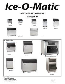
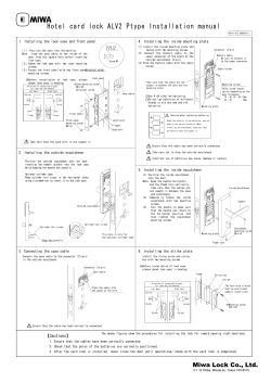
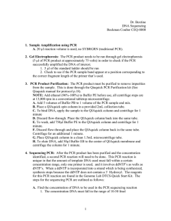
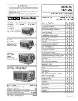
' FéB. e, 1968 � �G. J. UNDER, JR 3,367,252 PHOTOGRAPHIC APPARATUS � Filed Aug. 16, 1965 I ’ 6 Sheets-Shee't 1 40 83 INVENTOR. GEORGE J. LINDER ,JR. BY LACKENBACH 8: SIEGEL ATTORNEYS Feb. 6, 1968 ' _ G. J. LINDER, JR 3,367,252 PHOTOGRAPHIC APPARATUS Filed Aug. 16,-1965 6 Sheets-Sheet 2 IN VEN TOR. GEORGE J. LINDER,JR. BY LACKENBACH & SIEGEL ATTORNEYS Feb. 6, 1968 G. J. LINDER, Jé 3,367,252 PHOTOGRAPHIC APPARATUS Filed Aug. 16, 1965 as G0 W I 4 6 Sheets-Sheet Z 48 (as [52 ?ea “ D 1M�! 60 76 . PIC-5.6 FIG.R mo o I44 INVENTOR� f GEORGE a. LINDER,JR. Yale J I46 I BY LACKENBACH B�SIEGEL - - , ATTORNEYS Feb. 6, 1968 G. J. LINDER, JR 3,367,252 PHOTOGRAPHI C APPARATUS Filed Aug. 16, 196E ' 6 Sheets~Sheet 4 Lxii/206 $204 zl'si’ IN VENTOR. GEORGE J. LINDER,JR. BY. LACKENBACH 81 SIEGEL. ATTORNEYS Feb. 6, 1968 G.4J. LINDER, JR 3,367,252 PHOTOGRAPHIC } APPARATUS Filed Aug. 16, 196 6 Sheets-Sheét 5 PIC-5.20 INVENTOR. GEORGE J. LINDER,JR. BY LACKENBACH 8: SIEGEL ATTORNEYS Feb. 6, 1968 G. J. LINDER, JR 3,367,252 PHOTOGRAPH I C APPARATUS Filed Aug’. 16, 1965 6 Sheets-Sheet '@ HO H0 H4 H6 FIG.23 INVENTOR� GEORGE J. LINDER , JR. "BY LACKENBACH & SIEGEL ATTORNEYS lice on, an“ sass Patented Feb. 63 , i968 1 2 3,367,252 A further primary object of the present invention, in addition to each of the foregoing objects, is to provide PHOTOGRAPIHQ AKWARATUS photographic apparatus comprising an enclosure or hous George I. Linder, .lr., Mineola, N.Y., assignor to Qamera Corporation of America, Hiclrsville, tion of New York a corpora Continuationuimpart of application Ser. No. 171,988, Feb. 8, 1962. This application Aug. 16, 1965, Ser. 21 Claims. (Cl. 95--13) This application is a continuation-in-part of my co pending application Ser. No. 171,988, ?led Feb. 8, 1962, entitled “Magazine for a Camera,” and now Patent No. 3,200,725. The present invention pertains, gene-rally, to photog ing and a self-contained disposable unitary cartridge hav ing a supply of photosensitive material and a supply of developing solution or solutions disposed therewithin par ticularly adapted to be removably disposed within the housing, said housing or enclosure having a removable pivotable access door comprising a photosensitive mate rial or ?lm positioning assembly that is constructed and 10 arranged to enable a user to accurately and e'?iciently, and With maximum ease, facility and readiness, locate suc cessive portions of said photosensitive material or ?lm ?rst at an image plane of said cartridge, at which the 15 successive portions are particularly adapted to be exposed raphy, and more particularly to photographic apparatus to a subject image, thence Within a liquid-type chamber that is constructed and arranged to enable a user of the apparatus to cause the exposure of photosensitive ma within which the exposed portion of the photosensitive material or ?lm is particularly adapted to be developed before the next successive portion of the ?lm is disposed terial and its subsequent development all prior to its �re moval from said apparatus with maximum ease, facility 20 at the image plane for exposure to another subject image, and de?nably at a location in which the developed por and readiness. tion of the ?lm has been severed from the remainder of It is, therefore, a primary object of the present inven the photosensitive material, at Which latter location the tion to provide photography apparatus particularly next successive portion of the material or ?lm for expo adapted to co-onerate with a disposable unitary cartridge having a supply of photosensitive material therewithin, 25 sure to a subject image has been located at the image plane. said cartridge being constructed and arranged to enable An additional primary object of this invention, in addi a user to cause the exposure of said material and its sub tion to each of the foregoing objects, is to provide photo sequent development all prior to its removal from the graphic apparatus comprising an enclosure or housing apparatus with maximum ease, facility and readiness. Another primary object of this invention, in addition 30 and a self-contained disposable unitary cartridge having a supply of photosensitive material and a supply of de to the foregoing objects, is to provide unitary self-con veloping solution or solutions disposed therewithin par tained photographic apparatus that enables a user to cause ticularly adapted to be removably disposed within the the exposure of photosensitive material and its subse housing, said housing or enclosure having a removable quent development prior to removing the material from the apparatus with optimum e?iciency and maximum ease, 35 pivotable access door comprising a photosensitive mate rial o'r ?lm positioning assembly that is constructed and readiness and facility, said apparatus comprising a unitary arranged to enable a user to accurately and e??ciently, self-contained disposable cartridge having a supply of and with maximum ease, facility and readiness, locate said material and the requisite developing solution or successive portions of said photosensitive material or ?lm solutions therewi�thin, and an enclosure in which said cartridge is particularly adapted to be removably dis posed. 40 ?rst at an image plane of said cartridge, at which the suc cessive portions are particularly adapted 'to be exposed Yet another primary object of the present invention, in to a subject image, thence Within a liquid-type chamber addition to each of the foregoing objects, is to provide unitary self-contained disposable cartridge having a sup ply of photosensitive material and the requisite developing solution or solutions disposed therewithin particularly adapted to be removably disposed within the cartridge, Within which the exposed portion of the photosensitive material or ?lm is particularly adapted to be developed before the next successive portion of the ?lms is disposed at the image plane for exposure to another subject image, and de?nably at a location in which the developed portion of the ?lm has been severed from the remainder of the photosensitive material, at Which latter location the next said housing or enclosure comprising an image transfer successive portion of the material or ?lm for exposure to assembly for transferring a virtual image to said photo sensitive material, said image transfer assembly and said cartridge being constructed and arranged to co-operate a subject plane has been located at the image plane, said ?lm positioning assembly comprising an assembly for severing successive portions of the photosensitive mate with one another to de?ne the location of said cartridge rial or ?lm subsequent to the development of each of the unitary self-contained photographic apparatus comprising the combination of a camera housing or enclosure and a within the housing. A further primary object of this invention, in addition to each of �the foregoing objects, is to provide photography apparatus comprising an enclosure or housing and a self contained disposable unitary cartridge having a supply of photosensitivve material and a supply of developing solution or solutions in combination therewith, said hous ing or enclosure comprising an access door having a mounting assembly for removably and pivo'tally mount exposed portions. A further primary object of �this invention, in addition to each of the foregoing objects, is to provide a method for accurately locating and et?ciently �translating succes sive portions of a direct-positive type of photosensitive material or ?lm at and between an image plane, at Which the portions are particularly adapted to be exposed to a subject image, thence into a liquid-type container of a unitary self~contained disposable cartridge, Within which ing said door upon said enclosure or housing, said mount ing assembly being constructed and arranged to facilitate 65 the exposed portion of the material or ?lm is particularly adapted to be developed before the next successive por assembly and disassembly of said photographic apparatus, and the operation of said door. tion of the material or ?lm is translated to the image 3,867,252 3 ii plane, and ?nally to a location at which the developed of the �?lm positioning or locating assembly cooperate portion of the material or ?lm can be severed from the remainder thereof, in which latter location the next suc cessive portion of �the ?lm to be exposed to a subject with the access door; FIGURE 18 is an elevational view of one of the ele ments whereby the ?lm positioning or locating assembly image is located at the image plane. �Other objects and important features of the present is operatively associated with the access door; FIGURES 19 through 21 are schematic views illustrat ing the manner in which the ?lm positioning or locating assembly cooperates with the ?lm or photosensitive ma invention will be apparent from a study of the speci?ca~ tion following taken with the drawings, which together show, illustrate, describe and disclose a preferred embodi terial; ment or modi?cation of the invention and what is now 10 considered to be the best mode of practicing the principles thereof. Other embodiments or modifications may be . FIGURE 22 is a view similar to FIGURE 1, illustrat ing the assembly for pivotably removably mounting the suggested to those having the bene?t of the teachings access door upon the housing; FIGURE 23 is a plan view of one of the elements of herein, and such other embodiments or modi?cations are intended to be reserved especially as they fall within the mounting assembly shown in Fl URE 22; and 1the scope and spirit of the sub-joined claims. In the drawings: FIGURE 1 is an exploded perspective view of photo graphic apparatus constructed in accordance with the principles of the present invention, illustrating the self FIGURE 24 is an elevational view of the element shown in FIGURE 23. With reference now to the drawings, and particularly to FIGURE 1 thereof, there is illustrated therein photo~ graphic apparatus constructed in accordance with the principles of the present invention, and generally desig contained unitary disposable cartridge particularly adapted nated �by the reference character 36. The photographic to cooperate therewith for the exposure and subsequent development of photosensitive material or ?lm before the latter is removed from the apparatus; FIGURE 2 is a perspective view of an image transfer ranged to expose successive portions of photosensitive assembly for transferring a subject image to the photosen apparatus or camera 30, which is constructed and ar material or ?lm to a subject image, and to successively develop such portions before exposing the next successive portion all before they are each removed from the camera, sitive material or ?lm located at the image plane of the comprises an enclosure or housing 32 and a self~contained cartridge shown in FIGURE 1; unitary disposable cartridge 34. The cartridge 34 is shown, FIGURE 3 is a view similar to FIGURE 2, but taken illustrated and described and disclosed in the co-pending at a different angle; 30 application identi?ed above. Accordingly, since reference FIGURE 4 is a side elevational assembly view, illustrat may be had thereto for a detailed description of the car ing the manner in which the image transfer as embly tridge, it is not deemed necessary to present such a detailed shown in FIGURES 2 and 3 and the cartridge shown in FIGURE 1 cooperate with one another; FIGURE 5 is another assembly view, similar to FIG URE 4, and taken along the line 5-—5 thereof; description herein. Nevertheless, the cartridge 34 will be shown, illustrated, �described and disclosed to the extent 35 necessary to provide a clear understanding of the present invention. In this latter connection, it will �be understood tlv t the selfncontaincd unitary disposable cartridge 34 is particularly adapted to be used with conventional types of but wherein the assembly has been tilted upwardly from direct positive ?lm, such as, and by Way of example only, an horizontal plane to clearly illustrate certain details of 40 ?lms having a diazonium photosensitive layer, or having construction; two image forming �materials on a single backing web of FIGURE 7 is a rear elevational view of the photo material. A negative image will vthins be formed in one graphic apparatus, showing only the image transfer as image forming material by means of a �direct photosensitive sembly in its position therewithin; process, and a positive image formed in the second image FIGURE 8 is a side elevational view of the photo forming material by means of a diffusion transfer process, graphic apparatus, partially broken away, to further illus~ the negative image forming material and the positive image strate the manner in which the image transfer assembly forming material being either combined within a single and the self-contained unitary disposable cartridge co layer of emulsion or being in separate superposed layers operate with one another when they are positioned there of emulsion on a single web of backing material. The car FIGURE 6 is an elevational view of the image transfer assembly, viewed in the same direction as in FIGURE 5, within; tridge will also contain a suitable processing material com FIGURE 9 is a bottom plan view of the unitary self contained disposable cartridge; FIGURE 10 is an exploded perspective view of the access door for the photographic apparatus, illustrating the photosensitive material or ?lm positioning or locat prising the required solution or solutions rendering the ?lm capable of producing a positive image completely within the cartridge. The housing or enclosure 32, which is of generally rectangular construction, comprises one end or a rear end ing assembly that is operatively associated therewith; 36 that is open and substantially unobstructed. The hous FIGURE 11 is a bottom plan view of one of the ele ing or enclosure comprises another or front end 38. A ments of the ?lm positioning or locating assembly; lense and shutter system or assembly 40, which may be FIGURE 12 is a perspective view of an other element of any suitable and conventional construction, is ?xedly of the ?lm locating or positioning assembly; (50 positioned upon the housing 32 at the front end 38 thereof. FIGURE 13 is a perspective view of the photographic The housing 32 and the lensc and shutter assembly 4% apparatus, rbroken away, with the access door in a closed each comprise a top wall 42 and 44, respectively. A han position with respect thereto, and illustrating the ?lm locat ing or positioning assembly in one of its positions with respect thereto in solid lines, and in an other of its posi tions in phantom; FIGURE 14 is a plan view of the interior of the access door; FIGURE line ]l5—15 FIGURE line I6~16 15 is a ores-sectional View taken along the of FIGURE 14; 16 is a cross-sectional view taken along the of FIGURE 14; FIGURE 17 is a detailed view, drawn to an enlarged scale, illustrating the manner in which-certain elements dle 46 is mounted on the camera 30 at the top thereof, and. at one end is ?xedly positioned upon the top wall 42 of the housing 32, and at another end thereof, is ?xedly positioned on the top wall 4-4. The handle 46 is con structcd and arranged to de?ne a view-?nding assembly having a rear view ?nder 4-8 and a front view ?nder Sit in alignment with one another. An image transfer assembly, generally designated by the reference character 52, is ?xedly mounted in the hous ing or enclosure With particular reference now to FIGURES 2—4, the image transfer assembly will be seen to comprise a mounting wall that, when viewed in elevation, de?nes an opening of U-shaped con?guration. 5 3,367,252 The wall 54 comprises a plurality of mounting cars 58 and 60 each having apertures 62 to be aligned with aper tures in a wall (not shown) in the housing 32. As particu larly shown in FIGURE 6, a boss 64 aligned with one of the apertures 62, extends from each mounting ear 58, 50. One of the fasteners (not shown) for mounting the image transfer assembly 52 in the housing 32 will co-operate 6 against or engage a surface 92 of the cartridge opposite the image plane 80. The cartridge, thus, in effect, func tions as a pressure plate, and when the cars 84 abut against or engage the lugs 76, the ?lm passage 86 results and is thus de?ned. To provide optimum results, it is of course desirable that the ?lm 82 be ?at as it traverses the image plane. To this end, the side walls 74 and the image trans fer walls 66 of the assembly 52 are constructed and ar with each of the bosses 64. The latter, therefore, function ranged to de?ne a lip or ridge 94 of generally U-shaped as braces, and insures that the image transfer assembly will occupy a stable position within the housing. 10 con?guration (see FIGURES 5 and 6). Accordingly, when the resilient element or spring 90 moves the cartridge so The image transfer assembly comprises an image trans that the ears 84 engage the lugs 76, the ?lm passage 86 is fer wall 66 that extends from the mounting wall 54 at an de?ned, the extent of which is hardly more than a toler acute angle of 45 degrees with respect thereto. The wall ance. For all practical purposes, therefore, the lip 94 can 66 comprises an opening or aperture 68 of generally trape zoidal con?guration. An image transfer element "id is 15 be said to bear against the ?lm 82 to hold it ?at as it traverses the image plane 80, enabling the attainment of mounted upon the wall 66. As is considered readily ap optimum results. While no speci?c dimensions have been parent, the opening or aperture 68 will enable a substan given, it will be understood that they are of the utmost tial portion of the surface area of the element 70 to be exposed to the actinic light allowed to enter the housing importance to the extent that they must be chosen to 32 when the lense and shutter assembly 40 is operated. obtain the proper positioning and co-operation between the The image transfer element 70, by Way of example only, image transfer assembly 52 and the cartridge 34, and, in may comprise a conventional mirror. The back or rear turn, optimum results. surface of the mirror 76, as viewed in FIGURE 3, is As pointed out above, the photosensitive material or ?lm 82 is of the direct-positive-type. It will now be under? preferably covered with a backing material, for example, black paint, for a purpose that is considered readily ap stood, therefore, that the image transfer element 70 which, �by way of example only, may comprise a mirror, is an essential element of the image transfer assembly 52. That is, the conventional lens and shutter assembly 40 will, will be in a lateral direction towards a side wall '72 of the in the ordinary camera, reverse the image in transferring housing. The image transfer wall 66 therefore de?nes an 30 the latter to the ordinary negative-type of ?lm. The image acute angle of 45 degrees with a plane that is parallel with must then again be reversed in developing the positive. the front of the camera 33, and de?nes a similar angle in the present invention, since the ?lm is a direct-positive with the side wall '72. type, the subject image must be reversed in transferring The image transfer assembly 52 comprises, further, it thereto. That is, it is a virtual image that is transferred side walls 74 that are of generally triangular con?gura~ 35 to the ?lm 82, and thus the necessity for the image trans parent. With particular reference to FIGURE 1, it will be seen that the image transfer assembly 52 is positioned within the housing 32 so that any transfer of actinic light tion. Each side wall 74 comprises, in turn, locating or positioning guides or lugs 76 extending laterally outwardly therefrom. The guides or lugs 76 are particularly adapted to co-operate with the cartridge or magazine 34 in a man ner to be described more fully hereinafter. In this con fer element 70-. The particular position of the assembly 52 and the cartridge 34 within the housing 32 which transfers the subject image laterally of the housing to the ?lm 82 enables the presentation of photographic apparatus or the camera 30 that is compact and easy to handle. At this nection, and as shown, illustrated, described and dis closed in the aforesaid co-pending application, the car tridge comprises side walls 78, and is constructed and arranged to de?ne an image transfer plane 30 compris point, it will be understood that the housing 32 comprises a stop (not shown) therewithin to de?ne the innermost ing, in part, the path of travel of photosensitive material aging the element or mirror '7il. The photographic apparatus or camera 30 comprises, further, an access door, generally designated by the refer ence character 160, which is particularly adapted to be re movably and pivotaibly mounted or positioned upon the 50 enclosure 32. This is accomplished by means of a door or ?lm 82. The walls 78 each comprise locating or posi tioning ears 84 extending laterally inwardly therefrom. The ears 84, are particularly adapted to guide the ?lm' $2 and traverses the image plane 89, and in addition are particularly adapted to co-operate with the lugs '76. With particular reference now to FIGURE 5, it will be seen that the ears 84 perform a dual function. As pointed out above, they act as guides for the ?lm as it traverses the image plane $0. In addition, they function to de?ne the vertical position of the cartridge within the housing 32, to thus preclude any lateral displacement of the cartridge relative to the image transfer assembly 52. Accordingly, the transversed distance between the ears 84 is chosen to provide only a tolerance between them and the side walls 74 of the image transfer assembly, and the edges of the ?lms 82. With continued reference to that ?gure, it will be under stood that a clearance is provided between the image trans fer assembly and the image plane 80 of the cartridge 34 position of the cartridge 34, precluding the cartridge from �hitting the image transfer assembly 52 and possibly dam mounting assembly 102. The door mounting assembly comprises a boss 1% extending therefrom having a recess Hi6 at each end thereof. In the alternative, the boss 1% may simply have a passageway or bore (not shown) ex tending completely therethrough. The mounting assembly 102 further comprises a resilient element or spring 108 having a plurality of ?ngers 11% that are disposable within a corresponding one of the recesses 106. The spring 168 is of generally trapezoidal con?guration in a normal un flexed position, and de?nes a bight 112 and a plurality of legs 114. As clearly illustrated in FIGURE 24, the bight 112 is turned upwardly from the plane in which the legs 114 lie. Each of the legs 114i comprise a raised portion 116 for a purpose herein-after to be described. to provide a passage for the ?lm 82 therebetween. This 65 The mounting assembly 110 further comprises a block ?lm passage, designated by the reference character 86, is a or panel 118 which is positioned upon the other side wall function of the distance from or between the lugs �76 and 120 of the housing or enclosure 32. This side wall 120 has an edge 83 (see FIGURE 3) of the side Walls 74. This is a recess 122 which extends inwardly of the housing or particularly true since the lugs '76 are particularly adapted enclosure from the open end 36 thereof. The block or to rest upon the ears 84 when the cartridge 34 is disposed 70 panel 118 extends completely across the recess 122, in a co-operative position with the image transfer assem thus, in effect, substantially enclosing a portion thereof. bly 52. In order to ?rmly position the cartridge within the housing 32 so that the ears 84 will rest against the lugs 76, It will now be understood that the resilient element or spring 108 is insertable Within the recess 122. The legs a resilient element or spring $0 is mounted upon the side 114 thereof will engage an upper wall 124 and a lower wall 72 of the housing, and is particularly adapted to bear wall 126 of the recess, thus ?exing the legs inwardly to 7 8,367,252 8 any suitable material, and, for example, may be fabricated wards one another. The raised portions 116, which, like the bight 112, extend from the plane in which the legs 1114i lie, will abut against the block or panel 118, thus preclud ing any movement of the spring 108 between the side wall 120 of the housing 32 and the panel. A space is de or locating assembly, generally designated by the refer ?ned between the panel 118 and an end 128 of the recess ence character 174. With particular reference now to FIG 122, into which the bight 112 is insertable. In particular, the bight is particularly adapted to be snap~?tted into this URES 10-13 and 17, the assembly 174 will be seen to comprise a ?lm positioning or locating door 176 and a tear assembly 178 for severing successive portions of the of a spring steel. The photographic apparatus or camera 311 comprises, still further, a photosensitive material or ?lm positioning position, to thus preclude inadvertent movement of the resilient element along the recess. 10 photosensitive material or ?lm 82 from one another. The ?lm locating or positioning door 176 comprises a planar It will now be understood that the mounting assembly body 183* of generally rectangular con?guration, and a 192 enables the access door lltltl to be removably snap plurality of arms 182. The arms 182 each comprise an ?tted into a position with respect to the enclosure 32, in which position the door is pivotably movable between a ear 181%, each of which, in turn, is particularly adapted to be disposed within a corresponding one of the grooves closed position relative to the housing (see FIGURE 13) 156. With particular reference now to FIGURES 10 and and an opened position with respect thereto (see FIG 14, it will be understood that the height of each of the URES 1 and 22). Mounting the door is accomplished with facility by simply inserting the spring into the recess 122, arms 132 is substantially the same as the distance from the exterior surface 146 of the door 160 to the ?rst bot until the bight 112 is snap-?tted into a position within the space between the panel 118 and the end Wall 128 Of the 20 tom wall 138, so that the exterior surface of the ?lm lo cating or positioning door 1'76 will lie substantially ?ush recess. The raised portions 116 and the bight 11?. will co therewith when the latter is in the position shown in full operate with one another in retaining the spring in this lines in FlGURE 13. Similarly, the transverse dimension position, with the raised portions causing the spring to be of the door 176 is substantially the same as the distance frictionally engaged with the wall 120 of the housing and with the panel. The door is removed with equal facility 25 between the ledge 14-2 and the inside surface 136 of the wall de?ning the end 148 of the door 1%. As is clearly by simply placing a ?nger against the bight 112 and caus illustrated in FIGURE 14, a substantial portion of the ing it to enter the space between the Wall 120 and the door 1% lies within the space de?ned between the wall panel 118. This �may further be facilitated by pivoting the 158' and the inside surface 186. It is to be noted, at this end of the spring having the ?ngers 110 towards the wall point, that when the door 176 is in the position shown 72 of the housing 32. The access door 1% is particularly in full lines in FIGURE 13, the arms 132 are particularly adapted to be maintained in its closed position with re adapted to rest upon the ?rst bottom wall 13%;. As is now spect to the housing in any suitable manner, as through considered readily apparent, the door 17-2’; is particularly the medium of a conventional closure assembly 130 hav— adapted to be pivotably moved towards the position ing male and female closure elements 132 and 134, re shown in phantom in FIGURE 13. Accordingly, an edge spectively. 1%’ of the door is particularly adapted to pivot towards the With particular reference now to FIGURE 10, the door wall 151?. The door 176 comprises, further, a plurality liltl will be seen to further comprise a recess, generally of tits 190 mounted on the door along the edge 188 designated by the reference character 1%. The recess 136 thereof and, therefore, with the edge, are also particu is de?ned by a ?rst bottom wall 138, and a second bottom larly adapted to be pivoted towards the wall 1541. The wall 142%}. The bottom walls 138 and 140 lie in different spacing between the tits 1% is the same as the spacing planes, and a ?rst ledge 142 extends therebetween. A sec between the grooves 152, enabling the tits to enter a ond ledge 144 extends from the bottom wall 141} to the corresponding one of the grooves when the door is pivoted exterior surface 146 of the access door 111i). The ?rst to the position shown in phantom in FIGURE 13. It will bottom wall 1% extends towards one end 148 of the ac hereinafter be described in greater detail that each time cess door (the end upon which the male closure element the ?lm locating or positioning door 1'76 is moved to of the closure assembly 1% is mounted), and is separated the position shown in phantom in FIGURE 13, the pho therefrom by a wall 150, which comprises a plurality of vertically extending spaced apart grooves 152. One end of each of the grooves 152 de?nes a stop surface 154, the purpose of which will be described more fully hereinafter. The access door 16%, at each end of the wall 15s, is provided with a groove 15% which extends into the ?rst bottom wall 138 (see FIGURES 10 and 14). The interior surface 158 of the door is provided with a mounting boss 16% on either side of the ?rst bottom wall 138, which merges into a tapered bearing surface 162. A pair of re silient over-center ?oating assemblies generally designated by the reference character 1611, to be described more fully hereinafter, are mounted within the door, one end 166 of each such assembly being ?xedly positioned upon a cor responding one of the mounting bosses 16s in any suitable tosensitive material or ?lm 82 is positioned either to ex pose a portion thereof to a subject image, or to position a portion thereof that has been exposed to a subject image for development thereof. Accordingly, the position of the door 176 shown in phantom in FIGURE 13 can be de noted as a position for locating the photosensitive mate rial or ?lm 82. No movement of the film takes place when the door is in the position shown in full lines in that ?gure. The door 175 further comprises a camming lug 1&2 that extends laterally outwardly from each of the ears 184. The camming lugs 1% are of generally key-hole shaped con?guration, having a wide portion 194, and a narrow �portion 196, as particularly illustrated in FIG URES 19-—21. It will now be understood that the camming lugs 192 are each particularly adapted to be positioned manner, as through the medium of a fastener 168. It will now be understood that each assembly 164 is connected only at one end thereof to the door 189 and, at the other within a corresponding one of the resilient over-center end thereof, is free to move between and assume a plu 65 ?oating assemblies 164. More particularly, the wide por rality of substantially vertically spaced positions, one of tion 1% or" the lugs is disposed within the positioning loop which is illustrated in full in FIGURE 15, and the other one of which is illustrated in phantom in that ?gure. With particular reference now to FIGURE 18, each re silient over-center ?oating assembly 164 will be seen to comprise, further, a body portion 163- of curvilinear con tion 172 thereof between the positions illustrated and in phantom lines in FIGURE 18. It will be noted that the ?guration, a positioning loop 17% of substantially semi circular con?guration, and a cumming loop 172 that is in FlGURE 18, as well and the full and phantom-line also of curvilinear con?guration. Each of the resilient over-center ?oating assemblies 164 may be fabricated of with the same showings of the door 175 in FIGURE 13. 170 of the assemblies 164, while the narrow portion 196 is particularly adapted to ride along the camming por full and phantom lines showings of the cumming lug 1932, showings of the assembly 164 in FIGURE 15, correspond 3,367,252 16 an over-center spring. Thus, the inherent degree of resil iency of each of the assemblies or springs, and the normal tear strip 2% that will tend to move, or, in effect, pivot the projections 216 away from beads 218. Any other force will simply enable the projections to engage the beads 218, thus precluding the door 176 and the tearing assem position of the camming portion 172 relative to the body portion 168, is chosen to enable the camming portion to bly 178 from inadvertently being moved to that position. The teazing assembly thus performs the additional function As hereinbefore pointed out, the resilient ?oating as semblies 164 are each constructed and arranged to de?ne of locking the door 176 and the tearing assembly 178 exert a force against the narrow portion 196 of a magni in the position in which the ?lm either is being exposed tude sufficient to move the camming lugs to either of its to a subject image, or an exposed portion thereof is be positions once it has passed its center of movement. This center of movement may be de?ned by a line passed 10 ing developed. With particular reference now to FIGURES 1, 4 and through the center of the lugs and perpendicular to a 5, it will be understood that when the cartridge 34 is dis tangent of the camming portion 172. Accordingly, in mov ing the door 176 to its ?lm locating position, it is only posed within the housing 32, the photosensitive material necessary to move the door to an extent su?�icient to in or ?lm 82 will exit from the cartridge through an exit turn move the camming lugs just past their center posi 15 slot 229 which is in alignment with the space de?ned be tween the wall 159 and the inner surface 186 when the tion. The ?oating springs 164 will then take over and door 176 is in a position in which the ?lm is either being move the door 176 the rest of the way. Once the door is exposed to a subject image, or an exposed portion thereof in its ?lm locating position, it will be maintained therein is being developed (shown in full lines in FIGURE 13). by the ?oating assemblies or springs 164. The reverse is similarly true. 20 It is for this reason, that, as hereinbefore pointed out, photographic apparatus or the camera 30 constructed in As hereinbefore pointed out, the ?lm locating or posi accordance with the principles of the present invention is tioning assembly 174 comprises a tearing assembly 178 virtually self-threading. It will further be understood that, for severing successive portions of the photosensitive ma once the ?lm 82 has entered this space, it is turned so that terial or ?lm 82. With particular reference now to FIG URES 10, 12, 13 and 17, the tearing assembly or tear 25 it will traverse the bottom walls 138 and 140, and thence will exit the camera between the second ledge 144'- and strip 178 will be seen to comprise a top wall 196, a front the tear strip 200. wall 198 and a tear strip 206 having a serrated edge 202. It has hereinbefore been pointed out that the door The tearing assembly 17 8 further comprises a plurality of 176 and the tearing assembly 178 comprise a ?lm locat side walls 204 which are each of generally L-shaped con ing or positioning assembly. With particular reference ?guration. One leg 206 of each side wall is particularly now to FIGURES 19—21, and assuming that the cartridge adapted to function as a tab. More particularly, the legs 34 has been inserted within the housing 32, and the access or tabs 2&6 are insertable through slots 298 of the body door 1% moves to a closed position, as clearly illustrated portion 180 of the door 176. The legs or tabs 206 are in FIGURE 13, it is necessary to move the ?lm locating then folded towards one another, and are particularly adapted to be disposed within recesses 21% provided in 35 assembly to a ?lm locating position in order to bring the the under surface of the body portion 180. The tabs 206 ?rst portion of the ?lm to a position upon the image are not ?xed within the recesses 211), there resulting some plane 86. The door 176 is thus pivoted or moved to the play between the tearing assembly 178 and the door 176, position shown in FIGURE 19 by grasping the tearing as sembly 178 in the manner hereinbefore set forth. As the the purpose of which will be described more fully herein after. 40 door is pivoted to this position, the cam 192 will pass its center position, enabling the camming portion 172 to The other leg 212 of each of the side walls 204 de?nes bear against the narrow portion 196 and maintain the an edge 214- which, when the tabs 296 have been in door 176 in this position. In so moving the door, the tits serted through the slots 208 and turned or folded into 190 will have been pivoted to a position in which they the recesses 210, are particularly adapted to rest upon rest upon a ?lm leader that is presented when the door the surface of the body portion 1% of the door 176, as 176 is, in effect, ?rst opened. The ?lm leader can now particularly illustrated in FIGURE 13. The dimension be grasped, and the ?lm 82 pulled or moved to a position of the front wall 193 is then chosen to dispose the tear in which a ?rst pair or plurality of apertures 222 are in strip 200 substantially adjacent the second bottom wall alignment with the tits 190. Due to the tension of the 140. camming portion 172, a further movement of the door With particular reference now to FIGURES 10, 12 176 to a ?lm locating position (clockwise as viewed in and 17, the tear strip 200 will be seen to comprise a plu FIGURE 19) will take place, thus causing the tits 190 rality or pair of reverse projections 216 at each end there to pass through the apertures 222 and into the grooves of. The terminology “reverse” is intended to mean that 152 in the Wall 150, as clearly illustrated in FIGURE 20. the projections 216 extend upwardly from the plane of The user continues to pull the ?lm leader, during which the tear strip 200, at an obtuse angle with respect thereto, = movement the door 176 will move in a vertical direction towards the front wall 198. These projections are par as shown in that ?gure, and the tits 190 will ride Within ticularly adapted to engage or co-operate with a corre the grooves 152 until they engage or bottom-out upon the sponding one of a pair or plurality of beads 218 which surface 154. This movement of the door can take place extend inwardly towards one another from the walls of since the over-center assemblies 164 are inherently re the recess 136 in the door 100 (see FIGURE 10). As clearly shown in FXGURE 17, when the door 176 and the (30 silient, and are ?xedly mounted within the access door 1% only at the mounting bosses or surfaces 160. The tearing assembly 178 is in the position in which a por fasteners 168 thus, in effect, become a fulcrum point about tion of the photosensitive material or ?lm 32 is being sub which the assemblies 164 pivot when the door 17 6 is Ipulled jected to an image, or an exposed portion is being devel in the aforesaid direction by the ?lm 32. The resilient over oped (shown in full lines in FIGURE 13), the tear strip center assemblies 164 are thus ?oating assemblies, as 2-00 will be disposed or located substantially adjacent the hereinbefore pointed out, and are movable between a second bottom wall 140, as pointed out above. Accord normal position illustrated in FIGURES 19 and 20, and ingly, the projections 216 will be disposed or located in shown in phantom in FIGURE 15, and a ?exed position, a position in which they are engageable with the beads clearly illustrated in FIGURE 21. It is in this latter posi 218. It was hereinbefore pointed out that the connection between the door 176 and the tearing assembly 178 pro vides for some play therebetween. When it is desired to move the door 176 and the tearing assembly 178 to the ?lm locating position, it is necessary to grasp the tearing O tion that the door 176 has been pulled along with the ?lm 82 until the tits 1% have bottomed-out upon the surface 154 of the grooves 152. It will now be understood that the resilient ?oating assemblies 164 tend to bias the door 176 to its normal position, and must therefore be assembly in such a manner as to exert a force upon the 75 ?exed in order to allow the door 176 to be moved to the l3 3,367,252 position shown in FIGURE 21. This latter position is not only de?ned by the engagement between the tits 1M} and the surface 154 of the grooves 152, but also by en gagement of the body portion 163 of each of the ?oating assemblies 164 with the bearing surface 162 (see FIG URE 15) of the access door ll?tl. A ?rst successive portion of the photosensitive material or ?lm is now positioned at the image plane 34} of 12 tits I99 ride within the grooves 152; until they once again bottom-out upon the surface I54 thereof. At this time, the exposed portion of the ?lm will be located within the liquid-type developing chamber of the cartridge 34. It is necessary to now close the door 176. As the door is piv oted to its closed position, it will ?oat towards the bot~ tom wall 138 and return to its normal position with re spect thereto under the biasing action of the ?oating as the cartridge 34, and is particularly adapted to be ex semblies 164. The user now waits the required time for posed to a subject image in a manner that is considered 10 the exposed portion of the ?lm to be developed. It is to readily apparent to �those skilled in the art. The film lo be understood that during this time an exposable portion caring and positioning assembly 176 is now pivoted or moved to the position shown in full. lines in FIGURE 13. In this position and as hereinbcfore pointed out, the tear ing assembly 178 will lock the door 1'76 against being in advertently opened because of the engagement between of the ?lm 32 is not located upon the image plane 80 of the cartridge 34. The required time for the developing having expired, the door 176 is again moved to a ?lm lo cating position, and the tits 190 pivoted to a location just behind the set of locating apertures 222 from which they ?rst successive portion of the ?lm has been exposed, it have previously been disengaged. The ?lm is pulled by the user, and the developed portion of the~?lm severed is necessary to move it into the liquid-type chamber of by means of the tear strip 200 in a manner that is con the reverse projections 216 and the beads 218. After this the cartridge 34 that contains the requisite developing 20 sidered readily apparent to those skilled in the art. In re solution or solutions. moving the developed portion of the ?lm and severing it, The tearing assembly 178 is now grasped in the manner the next successive portion of the ?lm capable of being aforesaid (to preclude engagement between the projections exposed to a subject image is moved into position upon 216 and the beads 218 at this time), and the door 175 the image plane 80 and is properly located by means of once again moved to the position shown in FIGURE 19. 25 the next set of locating apertures 222. The door 176 is At this point, it is to be noted that when the door 17-6 again closed, and the procedure repeated until all of the was closed, the ?oating assemblies 164 moved the door available exposable portions of the ?lm 82 have been towards the bottom Wall 133 (vertically downwardly in exposed to a subject image and developed. At such time, the schematic illustrations of FIGURES l9—2l) due to the access door 100 is opened, in a manner considered the biasing force exerted thereagainst� As a result, when readily apparent to those skilled in the art, and the used the door 1% is once again moved to a ?lm locating po cartridge 34 removed from the enclosure 32. The used sition, the tits 1% will have been pivoted to a location cartridge can now be disposed, and a new cartridge po in which they once again rest upon the ?lm 82 just be sitioned in its place. hind the ?rst set of locating apertures 222. It can readily The photosensitive material or ?lm 82 will thus be be seen that in the absence of this ?oating movement of seen to comprise a plurality of sets of locating apertures the door 176 the tits 1% would tend to reenter the same 222. It can be said that two di?erent types of locating set of locating apertures 22?; from which they are dis apertures are provided. One such type is to locate an engaged each time the door is moved to its closed po exposable portion of the ?lm upon the image plane 8G. sition. This ?oating movement of the door occurs in two The other type can be said to locate the exposed portion phases: in the ?rst phase, after the tits 1% are engaged 40 of the ?lm in the liquid-type developing chamber of the within a set or pair of locating apertures 222, the door cartridge 34. It is to be remembered that when an ex is moved or floated away from the bottom Wall 138; in posed portion of the film is located in the developing the second phase, when the door is pivoted to a closed �chamber, the next successive exposable portion thereof position and the tits 1% are disengaged from the locating has not yet been located upon the image plane. Accord apertures 222, the door ?oats or moves towards the bot re 01 ingly, the next set of locating apertures 22.2 will be of tom wall 138, and thus returns to its normal position. It the ?rst type, and the following set of the second type. is emphasized that when the door is again moved or It is again emphasized that the ?oating assemblies pivoted to a ?lm locating position, the tits 1% are pivoted 154.� are not only responsible for maintaining the door to a position in which they again bear upon the ?lm 82 at 1% in each of its positions, but actually urge it to these a location just behind the set of locating apertures 222 50 positions once the cams 192 have passed their center�posi 'rom which they were previously disengaged. Such a tion. In connection with the door 176, and as hereinbefore set of apertures 222i is illustrated in FIGURE 19 in phan pointed out, it is movable to a position in which it locates tom. It is also to be noted that each set of locating aper or positions the ?lm 82 for each of the hereinbefore de— tures 222 will be positioned at the surface 154 of the scribed purposes. This position can, for purposes of sim~ grooves 152 when the door 176 is to be moved to a plicity, be described as an “open” position with respect closed position, and the tits 1% disengage therefrom. to the access door l?ll. The door 176 is also movable to The door is maintained in each of its positions by the another position in which a successive portion of the ?lm camming portion 172 of the ?oating assemblies 164, is either being exposed to a subject image, or an exposed and is actually urged to each of these positions by the portion thereof is being developed. This latter position camming portion once the cams 192 have passed their 60 of the door 176 can, for purposes of simplicity, be de center position, as hereinbefore pointed out. scribed. as a “closed” position with respect to the access A ?rst portion of the ?lm 82 has now been exposed, it door lltltl. In addition, and as hereinbefore pointed out, is ready to be moved into the liquid-type developing the resilient over-center ?oating assemblies 164 enable the chamber of the cartridge 34, and the door 176 has been door to “float” towards the bottom wall 138, or a normal pivoted or moved to a ?lm locating position ( see FIGURE 65 or operative position. In this position, the door is capable 19), in which position the tits 195) have been pivoted to of performing its function of properly locating the ?lm a location in which it bears upon the ?lm just behind the 82. The ?oating assemblies 164 also enable the door to ?rst set of locating apertures 222 which was responsible ?oat away from the bottom wall 138, towards an inopera for such ?rst portion of the ?lm at the image plane 3t)�. The tive position. During this latter movement, the door will user again pulls on the ?lm until the next set of locating 70 be performing its function. Once it has reached its in apertures 222 is in alignment with the tits 1%, whence operative position, the ?lm will have been properly the latter enter the apertures and the grooves 152. The located, and the door can be moved no further until it user continues to pull the ?lm, thus pulling the door is returned to its normal or operative position. therewith, and causing it to ?oat away from the bottom While the invention has been shown, illlustrated, de wall 138. During this ?oating movement of the door, the scribed and disclosed in terms of an embodiment or 13 8,367,252 l4 of the invention should not be deemed to be limited by the precise embodiment or modi?cation herein shown, illustrated, described or disclosed, such other embodi said resilient element is disposable, and having: top and bottom walls engageable with the legs of ments or modi?cations intended to be reserved especially as they fall within the scope of the claims here appended. What is claimed is: 1. Photographic apparatus for exposing successive por tions of a photosensitive material to a subject image, and developing each such portion prior to locating the next 10 such portion in a position for exposure to the same or another such image completely within said apparatus com prising, in combination, a housing having: said housing for transferring a virtual image to a ration having a plurality of mounting ears; a plurality of side walls of generally triangular con?guration, each of said walls having a posi thereof; said access door comprising: an internal surface and an external surface; said tioning lug extending laterally outwardly there from; internal surface having: a plurality of mounting bosses and a corre sponding number of bearing portions, each of said mounting bosses and bearing por tions being disposed adjacent a side wall 35 of said access door; a plurality of end walls; the side walls and the end walls of said access door de?ning a recess extending from the external surface towards the internal surface thereof, said recess in 40 part being de?ned by: an image transfer wall extending from said mounting wall at an acute angle of 45 degrees therewith, and having: an opening of generally trapezoidal con?guration; and - an image transfer element positioned upon said image transfer wall presenting a substantial por tion of its surface area through said opening, and having: a backing of non~re?ective material on an a ?rst bottom wall and a second bottom wall; a ?rst ledge extending between said ?rst and sec ond bottom walls, and a second ledge extending between said second bottom wall and the exter 45 other surface thereof; said side walls and said image transfer wall being con structed and arranged, along an edge thereof, to present a ledge of generally U-shaped con?gura tion; said image transfer assembly being disposed in said housing to position said image transfer wall and � nal surface of said access door; 50 element at an acute angle of 45 degrees with respect to the second wall thereof, enabling said image trans fer element to re?ect rays of actinic light transferred thereto by said lens and shutter assembly laterally said ?rst bottom wall having a lip extending along an end thereof towards the internal surface of said inter. nal surface, said lip being spaced from the adjacent 55 a plurality of grooves extending towards said ?rst bottom wall each having a stop surface; and a channel in said ?rst bottom wall at each end of the lip extending towards said ?rst ledge; a mounting assembly for removably and pivotally 60 mounting said access door on said housing, and comprising: a boss positioned on said door and extending there 65 a resilient element of generally trapezoidal con?guration in an un?exed condition, and comprising: a plurality of legs each having a ?nger at 70 one end thereof insertable within the tion extending from the plane in which said element lies; and a bight extending from the plane in which an image transfer assembly ?xedly positioned within a mounting wall of generally U-shaped con?gu an access door removably and pivotally mounted on said housing at the rear open and unobstructed end recesses of the boss, and a raised por door; and a female closure element positioned upon the ex photosensitive material, and comprising: shutter assembly; a recess at each end thereof; a male closure element positioned upon the access me; a front view ?nder in alignment with said rear-view ?nder mounted on the top of said lens and 25 from, said boss having: of, and comprising: terior surface of the second wall of said hous a rear-view ?nder mounted on the top wall of said enclosure at the rear end thereof; and end wall of said access door to de?ne a space there side wall thereof engageable with the raised portions of the legs; said panel being spaced from the end wall of the chan access door in a closed position with respect to the housing at the rear open and unobstructed end there the front end thereof having: a top wall lying in the same plane and being ?ush 20 with the top wall of said housing; a handle and view-?nding assembly comprising: between, and comprising: an end wall; a panel extending across said channel and de?ning a nel to de?ne a space within which the bight of said and at least a top wall and ?rst and second side walls; a lens and shutter system mounted on said housing at in a direction towards one another; said element to ?ex them towards one another; and element is disposable; a closure assembly for removably maintaining said a front end and a rear open end and unobstructed end; a plurality of heads extending outwardly of said second bottom wall towards the internal surface of said door substantially at said ?rst ledge and : said element lies in the same direction as said raised portions; a channel in the ?rst wall of said housing within which modi?cation which it has assumed in practice, the scope towards said second wall perpendicularly with re spect thereto, further enabling a virtual image to be transferred towards said second wall; a removable unitary self-contained disposable cartridge positioned within said housing in a cooperative re lationship with said image transfer assembly, and comprising: a supply of photosensitive material; said photosensitive material having successive sets of locating apertures of a plurality of different types, one of said types being adapted to posi tion a portion of the material at an image plane across which it is traversable for exposure to a subject image, and another type being adapted to position the exposed portion of the material in a liquid~tight developing chamber disposed between the image plane and an opposite sub stantially planar bottom surface of the cartridge before the next portion capable of being exposed is located at the image plane; a plurality of side walls each having: 8,367,252 a plurality of guiding ears extending laterally from the side Walls towards one another; said ears being adapted to guide said mate rial as it traverses the image plane, and being engageable with the side walls of said image transfer assembly when the 16 an open or ?lm locating position with respect there to; the edge of said door, as the latter is pivoted to its open position, pivotally moving towards the lip of said ?rst bottom wall, enabling the tits to enter the grooves thereof, subsequent to their engagement with said locating apertures, and as the pivoting movement of the door continues, further enabling the tits to cartridge is disposed in cooperative rela tionship therewith; the lugs of said image transfer assembly and the ears of said cartridge being engageable with one another 10 when the assembly and cartridge are disposed in said relationship with one another, and the spacing between the lugs and the edges of the side walls of said assembly being chosen to de?ne a passage for the photosensitive material between the ledge and said image plane, said ledge being in virtual contact with said material to maintain it ?at as it traverses the image plane; and an exit slot for said photosensitive material at the rear of said cartridge adapted to be disposed in alignment 20 with the. space between the lip and the end wall of said access door when the latter is in a closed posi tion with respect to said housing; the second wall of said housing having a resilient ele ment mounted thereon for bearing against the bot tom surface of said cartridge and urging the ears into engagement with said lugs, enabling the car— move along said grooves and bottom-out on the stop surface thereof; the engagement of said tits with said locating apertures as the photosensitive material is grasped and pulled from the space in said access door, and along the ?rst and second bottom walls, enabling a force to be exerted on the ?oating door of su?icient magnitude to overcome the biasing force of said resilient as semblies, further enabling the door to ?oat towards the external surface of said access door until the tits bottom-out and the body portion of said assemblies bears against the bearing portion of the internal sur face thereof; said resilient ?oating assemblies maintaining the ?oat ing door in each of its positions with respect to the access door, and urging the ?oating door towards each of such positions once the narrow portion of the camrning lugs pass their center of movement along the camming portion of said assemblies; and a tearing assembly positioned in cooperative relation— tridge to function as a pressure plate and, in con junction with the ledge, maintain said material flat 30 at it traverses the image plane; a plurality of resilient over-center ?oating assemblies mounted within said access door adjacent a corre ship with said ?oating door; and comprising: a top wall having: a plurality of side walls each being de?ned by: a tab insertable within the slots in the body of sponding one of the side walls thereof, and compris said ?oating door, and adapted to be turned mg: towards one another subsequent to inser a mounting portion ?xedly positioned upon the tion therewithin; and a leg having an edge bearing upon the bod mounting bosses; _a curvilinear body portion extending from the mounting portion towards the space in said access door; a positioning loop; and a camming portion; of said ?oating door; � a front Wall perpendicular to said top wall; and a tear strip lying in a plane parallel with the plane in 410 a ?oating photosensitive material or ?lm locating as sembly positioned to cooperate with said access door, and comprising: 45 a ?oating door having; a planar body; a plurality of tits engageable with successive sets of alternately different types of said locating apertures mounted on said body along an edge thereof at an obtuse angle with respect thereto; a plurality of slots in said body portion; a plurality of arms each having an ear of semicircular con?guration; and a camming lug extending outwardly of each of said ears of generally key-hole-shaped con?guration, said camming lugs each hav ing: which the top wall lies, said tear strip having: a serrated edge; and a reverse projection engageable with the beads on said access door when the ?oating door has been pivotally moved to a closed position with respect thereto, in which position the tear strip will be disposed substantially adjacent the sec ond bottom wall and between the ?rst and sec ond ledges; the cooperative relationship between. the tearing as sembly and said ?oating door presenting play there between, enabling said reverse projections to engage the beads and lock the door in its closed position until the tearing assembly is grasped in a manner to, in effect, pivot it in a direction to effect disengage ment therefrom. 2. Photographic apparatus for exposing successive por tions of a photosensitive material to a subject image, and developing each such portion prior to locating the next successive portion in a position for exposure to the same a wide portion particularly adapted to 60 or another such image completely within said apparatus dispose in the positioning loop of a comprising, in combination: corresponding one of said resilient over-center ?oating assemblies, and a narrow portion adapted to engage and move along the camming portion there 65 of; said ears being positionable within the chan nels in said ?rst bottom wall; said resilient ?oating assemblies exerting a biasing force against the ?oating door tending to normally dispose the door in a position in which the arms sub stantially rest upon the ?rst bottom wall; S’ild ?oating door being pivotally movable between a closed position with respect to said access door, and a housing; an access door removably and pivotally mounted on said housing; - a mounting assembly for removably and pivotally mounting said access door on said housing; an image transfer assembly ?xedly positioned within said housing for transferring a virtual image to a photosensitive material; a removable unitary self-contained disposable cartridge positioned within said housing in a cooperative re lationship with said image transfer assembly, and comprising: a supply of photosensitive material; 3,367,252 18 17 a plurality of grooves extending towards said bottom wall and having a stop surface. 10. Photographic apparatus as de?ned in claim 9, wherein said ?oating photosensitive material or ?lm locat a ?oating photosensitive material or film locating assembly positioned to cooperate with said ac cess door; a plurality of resilient over-center ?oating assem blies for mounting said ?oating door in a ?oat ing relationship with said access door; and a tearing assembly positioned in cooperative rela tionship with said ?oating door for severing the successive portions of said photosensitive mate rial subsequent to the development of each such portion. 5 ing assembly comprises: a ?oating door having a plurality of tits engageable with successive sets of alternately different type-s of said locating apertures; a plurality of arms each having an ear of semi-circular 10 3. �Photographic apparatus as de?ned in claim 2, where in said image transfer assembly comprises: ' a plurality of side walls each having a positioning lug extending therefrom; an image transfer wall having an opening; and an image transfer element positioned upon said image transfer wall presenting a substantial portion of its surface area through said opening; said side walls and said image transfer wall being con con?guration; and a camming lug extending outwardly of each of the cars. 11. Photographic apparatus as de?ned in claim 10, wherein: said access door further comprises a channel in said one bottom wall at each end of the lip; the ears of said ?oating door being positionable within the channels in said one bottom wall; wherein, said resilient over-center ?oating assemblies comprise: a positioning loop; and a camming portion; and wherein, said camming lugs comprise: a portion particularly adapted to be disposed in the positioning loop of a corresponding structed and arranged to present a ledge. 4. Photographic apparatus as de?ned in claim 3, where in said cartridge comprises: one of said resilient over-center ?oating assemblies, and another portion adapted to a plurality of side walls each having: a plurality of guiding ears extending therefrom 25 engage and move along the camming por tion thereof; said resilient ?oating assemblies exerting a biasing force against the ?oating door tending to normally towards one another; said ears being adapted to guide said material as it traverses an image plane for exposure to a subject image, and being engageable with the side walls of said image transfer assembly when 30 the cartridge is disposed in cooperative relation ship therewith; dispose it in a position in which the arms thereof substantially rest upon said one bottom wall; said ?oating door being pivotally movable between a closed position with respect to said access door, and the lugs of said image transfer assembly and the an opened or ?lm locating position with respect ears of said cartridge being engageable with one another when the assembly and cartridge are said tits, as the ?oating door is pivoted to its opened thereto; position, being pivotally moved towards the lip of disposed in their cooperative relationship�. 5. Photographic apparatus as de?ned in claim 4, where in: the spacing between the lugs and the ledge is chosen to de?ne a passage for the photosensitive material 40 between the ledge and the image plane, said ledge being in virtual contact with said material to main tain it ?at as it traverses the image plane. 6. Photographic apparatus as de?ned in claim 5, where in said photosensitive material comprises: said one bottom wall, enabling them to enter the grooves thereof subsequent to engagement with said locating apertures, and as the pivoting movement of the door continues, further enabling the tits to move along said grooves and bottom-out on the stop sur face thereof; 45 successive sets of locating apertures of a plurality of different types, one of said types being adapted to position a portion of the material at said image - the engagement of said tits with the locating apertures as the photosensitive material is grasped and pulled from the space in said �access door, and along said one bottom wall, enabling a force to be exerted on the ?oating door of su?icient magnitude to over come the biasing force of said resilient assemblies, further enabling the door to ?oat away from said plane, across which it is traversable for exposure to a subject image, and another type being adapted to 50 position the exposed portion of the material in a developing chamber of the cartridge before the next portion capable of being exposed is’located at the image plane. 7. Photographic apparatus as de?ned in claim 6, where 55 in there is provided: a resilient element for hearing against said cartridge and urging the ears into engagement with said lugs, enabling the cartridge to function as a pressure plate, and, in conjunction with the ledge, maintain said _ one bottom wall until the tits bottom-out on the stop surfaces; said resilient ?oating assemblies maintaining the ?oat ing door in each of its positions with respect to the access door, and urging the ?oating door towards each of such positions once the other portion of said camming lu-g-s pass their center of movement along the camming portion of said assemblies. 12. Photographic apparatus as de?ned in claim 11, 60 wherein said access door further comprises: 1 photosensitive material ?at as it traverses the image an internal surface and an external surface; plane. said internal surface having: a plurality of mounting bosses and a correspond ing number of bearing portions, each of said 8. �Photographic apparatus as de?ned in claim 7, where in said access door comprises: a recess being de?ned at least in part by: a plurality of bottom walls; one of said bottom walls having a lip extending along an end thereof, and being spaced from the access door to de?ne a space therebetween particularly adapted to be disposed in alignment 70 with an exit slot for the photosensitive material in the cartridge when the access door is in a closed position with respect to said housing. 9. Photographic apparatus as de?ned in claim 8, where in the lip of said one bottom wall comprises: 75 mounting bosses and bearing portions being dis posed substantially adjacent a side wall of said access door; a plurality of end walls; the side walls and the end walls of said access 'door de?ning said recess therein which extends from said external surface towards the internal surface thereof; and wherein: I said resilient over-center ?oating assemblies fur ther comprise: 3,367,252 19 29 a mounting portion ?xedly positioned upon the mounting bosses; and a curvilinear body portion extending from wherein, said mounting assembly for removably and piv otally mounting said access door on the housing corn prises: the mounting portion towards the space ’ a boss positioned� on said door having a plurality of in said access door. 5 13.. Photographic apparatus as de?ned in claim 12, vwherein: said access door further comprises a ?rst ledge extend~ ing between said plurality of bottom walls, and a second ledge extending �between another of said bot it) tom walls and the external surface of said access door; and a plurality of beads extending outwardly of said other bottom wall towards the external surface of said ac cess door substantially at said ?rst ledge and in a direction towards one another, and wherein said ?oat recesses; a resilient element comprising a plurality of lugs each having a ?nger at one end thereof insertable within the recesses of the boss, and a raised portion extend ing from the plane in which said element lies; and a bight extending from the plane in which said element lies in the same direction as said raised portions; a channel in an other wall of said housing within which said resilient element is disposable, and having: top and bottom walls engageable with the lugs of said element to ?ex them� towards one another; and ing material locating assembly further comprises: > an end wall; a tearing assembly postioned in cooperative re a panel extending across said channel and de?ning a side wall thereof engageable with the raised lationship with said ?oating door, and compris mg: 20 a top wall having a plurality of side Walls each being de?ned by a tab insertable with portions of the lugs; said panel being spaced from the end wall of said channel� to de?ne a space within which the bight in a corresponding one of a plurality of slots of said element is disposable. provided in said ?oating door, and adapted 18. In combination with a removable unitary self-con~ to be turned towards one another subse- ' quent to insertion therewithin; and a tear strip having a serrated edge; and a reverse projection engageable with the beads on said access door when the ?oating door has been pivotally moved to a closed posi 30 tion with respect thereto, in which posi tained disposable cartridge, having a supply of photosen sitive material, particularly adapted to be removably dis~ posed within the housing of a photographic apparatus for exposing successive portions of said material to a subject image, and developing each such portion prior to locating the next such portion in a position for exposure to the same or another such image completely therewithin, said tion the tear strip will be disposed substan cartridge comprising: tially adjacent said other bottom wall and an image plane particularly adapted to be traversed by between the ?rst and second ledges; said photosensitive material; and the cooperative relationship �between the tearing assem- " a plurality of side walls each having a plurality of guid - bly and said ?oating doors presenting play therebe ing ears; tween, enabling said reverse projections to engage the an image transfer assembly disposable in cooperative beads and lock the door in its closed position until relationship with said cartridge for transferring a vir the tearing assembly is grasped in a manner to, in tual image to said photosensitive material, and com effect, pivot it in a direction to effect disengagement ~10 prising: therefrom. a plurality of side walls each having a positioning 14. Photographic apparatus as de?ned in claim 13, 111a; wherein said image transfer assembly further comprises: an image transfer wall having an opening; and a mounting wall; and wherein: an image transfer element positioned upon said said image transfer wall extends from said mount image transfer wall presenting a substantial por ing wall at an acute angle with respect thereto; tion of its surface area through said opening; said image transfer assembly being disposed in said said ears being adapted to guide said material as it housing to position said image transfer wall and traverses the image plane, and being engageable element at an acute angle with respect to a wall With the side walls of said image transfer assem of said housing, enabling said image transfer bly when the cartridge is disposed in cooperative element to re?ect rays of actinic light trans relationship therewith; ferred thereto laterally towards the said wall, the lugs of said image transfer assembly and the further enabling a virtual image to be trans ears of said cartridge being engageable with one another when the assembly and cartridge are ferred thereto, 15. Photographic apparatus as de?ned in claim 14, wherein said ?oating door comprises: disposed in said cooperative relationship. 19. The combination as de?ned in claim 18, wherein: an edge of the side walls and an edge of said image trans fer wall being constructed and arranged to de?ne a ledge; and wherein: a body having an edge along which said tits are dis posed at an obtuse angle with respect thereto. 16. Photographic apparatus as de?ned in claim 15, wherein said housing comprises: the spacing between the lugs and the edge of the side: a front end and a rear opened and unobstructed end at which said access door is removably and pivotally walls is chosen to de?ne a passage for the photosen mounted; plane; at least a top wall; a lens and shutter system mounted on said housing at the front end thereof having; . sitive material between the ledge and said image: 65 a top wall lying in substantially the same plane as the top wall of said housing; a handle and view-?nding assembly comprising: ' a rear view-?nder mounted on the top wall of said 70 enclosure at the rear end thereof; and a front view-?nder in alignment with said rear view-?nder mounted on the top wall of said lens and shutter assembly. 17. Photographic apparatus as de?ned in claim 16, 7’_0 said ledge being in virtual contact with said material tov maintain it ?at as it traverses the image plane. 20. The combination as de?ned in claim 19, wherein: said image transfer assembly further comprises: a mounting wall; wherein: the side walls thereof are of generally triangular con?guration; and wherein: said image transfer wall extends from said mount ing wall at an acute angle therewith; enabling said image transfer assembly to re?ect raysv of actinic light transferred thereto generally lateral 1y towards the image plane of said cartridge, fur 3,867,252 21 ther enabling a virtual image to be transferred hthereto._ . . _ _ th 212:1“; tilombmatlgndf�s de?ned 1“ clam� 20" Where�“ em 1° “r er Pro“ 8 - 22 References Cited UNITED STATES PATENTS 3,053,160 3,113,497 9/1962 Bachelder et a1. ____ 95_13 XR 12/1963 Eloranta ____________ __ 95-43 a resilient element bearing against said cartridge for 5 urging the ears into engagement with said lugs, enNORTON ANSHER, primary Examiner_ abling the cartridge to function as a vpressure plate, 1 . and in conjunction with the ledge, maintain said ma- JOHN M’ HOR'AN’ Exammer� terial ?at as it traverses the image plane. G� M- HOFFMAN. Assistant Exammer .
© Copyright 2026 Paperzz