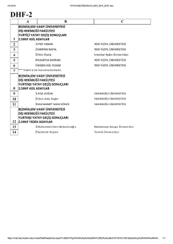
Dr. Müştak Erhan Yalçın
Emre Göncü
May 16, 2014
Circuit and System Analysis
Homework II
1)
a) Find the y- parameters in s- domain for the circuit given in Figure 1.
b) Obtain the Norton equivalent circuit with respect to terminals 2 and 2’ while connecting a current
source = sin(2 + 30°) across the terminals 1 and 1’.
c) Let an admittance = −5 + 2 mho be connected across terminals 2 and 2’. Determine the
active, reactive and average powers absorbed by the 2- terminal.
2) Determine the transfer function, / , for circuit given in Figure 2.
3)
a) Find the h- parameters in s- domain for the circuit given in Figure 3.
b) When
=
=
= 1 and
=
= 1Ω, across terminals 2
, and connecting a resistance,
and 2’, determine the input impedance,
( ).
4)
a) Using the block diagram given in Figure 4.b, obtain a block diagram for the circuit shown in
Figure 4.a.
b) Reducing the block diagram obtained in part 4-a, find the transfer function, ( )/ ( ).
3VR
+
1H
1 i1
i2
2
+
+
V1
-
VR
1/2F
1Ω
-
V2
2'
1'
Figure 1
YA
Y2
-µ
1+α
I1
YB
Y1
Figure 2
I0
Dr. Müştak Erhan Yalçın
Emre Göncü
+
1
May 16, 2014
I2 2
I1
Z4
Z1
+
V2
∞
+
+
2' -
∞
Z2
- 1'
Z3
Figure 3
3I0
Ikd
V1
2
+
Ik
1F
1Ω
I0
Figure 4.a
Ik
-
Ikd
V1
-
Figure 4.b
I0
© Copyright 2026 Paperzz