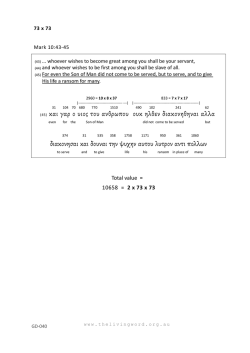
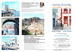
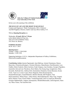
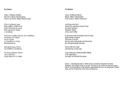
Τα Νέα
της Ε Ε Ε Ε Γ Μ
Αρ. 70 – ΟΚΤΩΒΡΙΟΣ 2014
70
ΠΕΡΙΕΧΟΜΕΝΑ
Άρθρα
3
- The Crossrail Project - Questions and Answers
3
- Choosing an Excavation Method Drilling Dilemmas
7
Νέα από τις Ελληνικές και Διεθνείς Γεωτεχνικές
Ενώσεις
13
- ISSMGE : TC308 - Energy Geotechnics
13
- EEΣYE : Δελτίο Τύπου
13
Διεθνείς Διαγωνισμοί : ΣΥΝΔΕΣΜΟΣ ΕΛΛΗΝΙΚΩΝ ΕΤΑΙΡΕΙΩΝ - ΓΡΑΦΕΙΩΝ ΜΕΛΕΤΩΝ Announcement of the
EFCA Young Professionals Competition 2015
15
Προσεχείς Γεωτεχνικές Εκδηλώσεις:
16
- Second International Course on Geotechnical and
Structural Monitoring
16
Ενδιαφέροντα Γεωτεχνικά Νέα
21
- 3-D printing of rocks and fossils
21
Ενδιαφέροντα – Σεισμοί
22
- New explanation for origin of plate tectonics: What
set Earth's plates in motion?
22
- Signs in groundwater may help predict earthquakes
six months in advance
22
- Earth's water is older than the sun: Likely originated
as ices that formed in interstellar space
23
Ενδιαφέροντα – Περιβάλλον
25
- Απολιθώματα γιγάντιας αρκούδας βρέθηκαν στα
Γρεβενά
25
Ενδιαφέροντα – Λοιπά
26
- 7 Most Dangerous Places on Earth
26
- Οι 23 φωτογραφίες από δορυφόρο που μοιάζουν με
έργα τέχνης
28
- Μαγικοί κύκλοι της Αφρικής: Νεράιδες-Επιστήμη 1-0
32
Νέες Εκδόσεις στις Γεωτεχνικές Επιστήμες
35
Ηλεκτρονικά Περιοδικά
36
ΤΑ ΝΕΑ ΤΗΣ ΕΕΕΕΓΜ – Αρ. 67 – ΙΟΥΛΙΟΣ 2014
Σελίδα 2
ΑΡΘΡΑ
imity to sensitive structures and services on several contracts.
The Crossrail Project
Questions and Answers
With a marathon’s worth of tunnels under one of the most
densely populated and complex cities in Europe, the sheer
scale of London’s new railway line is overwhelmingly impressive.
26 miles of tunnels are being built beneath London
•
For both TBM and SCL tunnels, controlling ground movements where protection of third-party assets was reliant
on controlled settlement as the main method of protection This has been further complicated where multiple
contracts have affected the same asset, where tunnels
have been constructed in close proximity to each other
and when tunnelling at shallow depth, close to third-party
assets.
Completed construction of the east-bound cavern at Stepney Green
•
The £15bn Crossrail project needs to accommodate 200
million passengers a year across a total of 100km of track
with 40 stations (including 10 new ones).
Regional dewatering of the deep aquifer to assist in the
construction of some of the cross-passages and deep
shafts.
•
On the Thames tunnel section (Plumstead to North Woolwich), the TBM drives and SCL cross-passages had to
cope with high water pressures, including a tidal variation
of 8m in very permeable strata.
Work began back in 2008 and most of the tunnelling is now
complete — but services won’t start running until 2018 so
there’s still plenty to do.
For the latest in our series of reader Q&As, members of the
engineering team behind Crossrail have answered your
questions on the difficulties and innovation of the project.
Which were the trickiest parts of London to tunnel
underneath and why?
Mike Black, Crossrail head of geotechnics, and Mike
King, Crossrail head of underground construction:
Crossrail is among the most ambitious infrastructure projects undertaken in the UK and will dramatically change
how people travel across London.
A total of 26 miles of train tunnels are being built beneath
the streets of London by eight tunnelling machines. The
tunnels are now more than 80 per cent complete and five
of the machines have completed their drives.
The project teams specified and procured machines and
equipment appropriate for the anticipated ground and
groundwater conditions, and have employed construction
methods suited to the ground and equipment chosen. As a
result the general tunnelling has been completed as
planned and as expected.
However, different areas have presented different challenges, based on the geology, groundwater conditions and
the local built environment. Some worthy of particular note
include:
•
Launching and completing TBM drives with only shallow
ground cover, in non-cohesive material and in close prox-
ΤΑ ΝΕΑ ΤΗΣ ΕΕΕΕΓΜ – Αρ. 67 – ΙΟΥΛΙΟΣ 2014
Why was it necessary for Crossrail to pass so close to
existing Tube lines? Couldn’t it have ‘dived’ underneath them?
Mike Black, Crossrail head of geotechnics: Crossrail
was designed to provide direct connections to London Underground and National Rail. Constructing Crossrail with
deeper tunnels and stations would have required an increased number of escalators and passageways to enable
passengers to not only access Crossrail services but also
interchange with the existing transport network. Not only
would this have cost implications but deeper tunnels and
stations would increase the time it took for passengers to
access and exit Crossrail platforms. Additionally, in the
event of an emergency, deeper stations would result in
longer evacuation times.
The project is using eight Tunnel Boring Machines (TBMs)
A further potential issue resulting from deeper tunnels
would be a wider zone of surface settlement. While the
magnitude of the vertical movement within this zone would
be less than for shallow tunnels, potentially more buildings
and utilities would be affected.
The Crossrail stations are situated as high points relative to
the running tunnels to allow for more energy-efficient brak-
Σελίδα 3
ing and acceleration of the trains when entering and leaving
stations.
less than 3mm, well within predictions, and a remarkable
feat given that the 1,000t TBM passed only 800mm above.
The current methods of station construction would become
very inefficient if the tunnels were deeper. The current configuration of open boxes at either end of the tunnelled stations would become impractical and stations would most
likely be limited to tunnel-only access to the platform levels. The ground loads and consideration of long-term design
loading for groundwater would also result in significantly
more robust structures and foundations.
What was the technical process used in ‘threading
the eye of the needle’ — tunnelling between the very
tight clearances between the escalators and the
Northern line at Tottenham Court Road?
Andy Alder, Crossrail project manager, western tunnels: Crossrail used an earth pressure balance (EPB) tunnel-boring machine (TBM) to mine the western-running
tunnels between Royal Oak and Farringdon. The EPB TBM
mined the section of tunnel directly above the operational
Northern line platform tunnels at Tottenham Court Road,
directly below the London Underground station structures,
with less than 800mm clearance to each.
The EPB TBM controls ground movement during the tunnel
mining by maintaining pressure on the clay being excavated
within the cutting face. The cutterhead rotates as the TBM
advances, cutting the clay with tungsten carbide cutting
tools. There is a steel bulkhead that creates the cutterhead
chamber, separating the cutting face from the inside of the
TBM. A screw conveyor removes the excavated clay from
the cutterhead chamber, and the speed of rotation of the
screw conveyor controls the clay pressure at the cutterhead. In this way the ground movement is controlled and
minimised. Foam is mixed with the clay to create the right
consistency of spoil to use the screw conveyor to maintain
pressure. Pressure in the TBM is monitored in real time to
allow it to be controlled.
A TBM is lowered into position
Behind the TBM, precast concrete segments are erected to
create the tunnel lining. Cement grout is injected around
the segments under pressure to lock the segments in the
ground, and to ensure that all voids are filled.
A laser guidance system is used on the TBM, to ensure that
its position is accurately known. Variable pressure on the
TBM shove rams around the circumference of the TBM is
used to control the TBM position to within ±50mm.
Automatic monitoring was undertaken in the Northern line
platform tunnels. This used an automatic theodolite to record the position of a number of prisms fixed to the existing
tunnel lining and record any movement. This data was analysed in real time to monitor the effect of the mining on
London Underground’s assets. Recorded movements were
ΤΑ ΝΕΑ ΤΗΣ ΕΕΕΕΓΜ – Αρ. 67 – ΙΟΥΛΙΟΣ 2014
TBM Victoria breaks through into Stepney Green cavern
Crossrail is routinely described as ‘Europe’s biggest
archaeology project’ as well as Europe’s biggest construction project. To what degree have archaeological
concerns hindered the progress of the project and
how have you dealt with them?
Jay Carver, Crossrail lead archaeologist: Archaeological
finds have tremendous potential to affect a construction
schedule. Unexpected finds are the key risk alongside access problems and logistics that in urban environments
often prevent an early start on the archaeology works. To
address this, we started at detailed design with a very
thorough research phase to understand the historic land
use at each of the 40 or so work sites. That allowed us to
assess what the actual quality of archaeological remains
was likely to be, and grade the programme risk — for example, the impact that archaeology delays could have on
subsequent works.
The Chaterhouse plague pit is one of Crossrail’s many archaeological finds
Combining those issues allowed us to assign each site a
critical, high, medium or low rating. Critical programme
sites included, for example, Liverpool Street ticket hall,
where the quality of the predicted archaeology (a deep sequence of Roman remains and a 16th century burial
ground) indicated that early site access was essential even
though it would not be easy. In that case, a road closure
and excavations to a depth of 6m was needed to fully quantify the risk.
Although we have had the occasional last-minute find, such
as the large haul of ice-age finds, right at the place where
the western tunnels were to start at Royal Oak Portal, a
daily working relationship with colleagues in construction
Σελίδα 4
management has meant that solutions have been found.
This includes acceleration of the work with increased resources and extended hours and carefully agreed work
stages to allow both construction and archaeology to continue concurrently.
Will there be any significant differences between the
engineering techniques used on Crossrail and Crossrail 2, if it happens?
for either ourselves or our contractors. The Crossrail Technical Assurance Plan (TAP) outlines how we manage and
accept designs from both our FDCs and contractors. The
TAP specifies a gated acceptance process, which incorporates single-discipline and inter-discipline reviews and gains
the concurrence of our infrastructure maintainers, London
Underground and Rail for London.
Chris Dulake, Crossrail chief engineer: It is envisaged
that the design and construction techniques for implementing Crossrail 2 main infrastructure will be very similar to
that deployed for Crossrail.
Crossrail 2 has a deeper alignment in parts through the
central area and will therefore present slightly different
challenges in terms of structural loading, and constructing
structures at depth. Potentially different predicted ridership
and passenger demands on Crossrail 2 may also determine
changes in station geometry and train lengths. However,
design and construction techniques are not expected to be
significantly different.
Achieving the acceptance gates for our contractors’ detailed
design is important to maintaining our critical path programme. Managing the contractors’ design in a manner that
considers the complexity of these interfaces is a top priority
of our project teams and chief engineer’s group every day.
What would the Crossrail team do differently in the
processes they adopted to manage the design and
other activities of their project that was done before
they started construction knowing what they do now
as they come to the end of their programme?
Patrick ten Have, Crossrail chief engineer’s group:
There are many opportunities to do things differently; the
question is always what would have made a difference?
An engineer checks on a TBM’s progress
Following on from experience gained on Crossrail and potential technological advances in the next few years, it is
possible that some of the ground movement monitoring
techniques and approaches will be different for Crossrail 2,
taking more advantage of fibre-optical systems, satellite
GPS technology and automated systems using analytical
techniques on real-time ground movement data.
What was the biggest engineering challenge that you
have encountered since starting the project and what
steps have you taken to overcome this?
Bill Tucker, Crossrail central section delivery director: The biggest engineering challenge on Crossrail, in my
opinion, is management of interfaces. The original design,
which carried the programme through the Crossrail Act,
was the product of three multi-discipline consultants
(MDCs). Framework design consultants (FDCs) were then
engaged back in 2009 to progress the design of the bored
tunnels, SCL tunnels, stations, portals and shafts to the
point that we could tender for construction contracts.
Now, we have our civil contractors performing temporary
works design and detailed design for mechanical, electrical
and architectural/fit-out of our stations, portals and shafts
using standard specifications developed by our FDCs. Other
FDCs also developed the conceptual design of our rail systems (track, traction power, HV power, signalling and
communications) that our rail systems design-build contractors are now taking through detailed design.
In total, approximately 30 design consultant companies
have been engaged in some aspect of the Crossrail design
ΤΑ ΝΕΑ ΤΗΣ ΕΕΕΕΓΜ – Αρ. 67 – ΙΟΥΛΙΟΣ 2014
Perhaps one area we would adopt for future programmes
like Crossrail would be to better understand the linkages,
constraints and interfaces between the design of the underground structures and the actual construction methodology
and timing thereof. This would involve completing the design to a greater level of detail prior to the award of the
construction contracts so as to avoid change and the knockon effect on other disciplines. Another consideration would
be reducing the overall number of interfaces between contracts by grouping the asset base into larger packages of
work and aligning the designers in the same fashion.
Have you been working with HS2 or any of the other
rail infrastructure improvement projects going on,
and how? What advice would you have for these
teams?
Chris Sexton, Crossrail technical director: Crossrail has
regular liaison with HS2, Thames Tideway Tunnel and
Thameslink, and works very closely with Network Rail and
London Underground as delivery partners for Crossrail.
It is always a challenge to offer relevant advice to another
project which is invariably facing similar but slightly different challenges. Apart from the number one priority of
safety, I would offer three areas of focus: design accountability; management of interfaces and integration; and
stakeholder engagement.
For design, ensure that accountabilities are clearly understood, BIM is fully adopted by all designers from the start
and sufficient time is allowed for a mature design to be
issued for construction.
Σελίδα 5
On a large programme the packaging and sequence of design contracts contributes to the complexity of the challenge and due weight needs to be given to how the design
will be assured and how the works are intended to be
handed over. Accountability for integration and managing
interfaces also need to be clear — not just on paper but
actively managed and rigorously and regularly checked.
Time spent on engaging stakeholders is never wasted; respect people who are affected by the works by minimising
the impacts of construction and being as good as you can
be in keeping promises and communicating what is happening in good time.
How well have the Crossrail tunnelling academies
helped fill your recruitment needs? What will all
those tunnellers do with their skills once the project
is over?
Valerie Todd, Crossrail talent and resources director: From the outset we identified that there was a shortage of talent in the labour market. We wanted to do something to re-energise the skills base within tunnelling and
underground construction particularly, but in rail engineering and infrastructure generally.
The Tunnelling and Underground Construction Academy
(TUCA) established by Crossrail in 2011 has been a huge
success. This has supported employers looking for workers
by providing pre-employment training, tunnel safety training, apprenticeships and advice and guidance to those
seeking work.
It was more cost-effective to leave the 2 TBMs Phyllis and
Ada buried in the ground
(Stephen Harris / theengineer, 27 October 2014,
http://www.theengineer.co.uk/your-questions-answeredcrossrail/1019411.article?cmpid=tenews_627713)
The first of Farringdon’s tunnels was completed in November 2013
Approximately 7,000 people have received some form of
training at TUCA, which has enhanced their employability
by equipping them with skills and experience valued by
employers.
New apprenticeships developed by Crossrail specifically for
the project include tunnel operations, gantry crane operations, locomotive operations and spray concrete lining;
while existing apprenticeships on offer include business
administration, procurement, document administration,
finance, HR, IT and accounting. Apprentices receive both
training in a college environment and hands-on application
in the workplace, and are employed by Crossrail itself, or
one of the programme’s numerous partners and contractors. Nearly 400 apprentices have worked on Crossrail to
date.
Following Crossrail there will be Thames Tideway, the
Northern line extension, HS2 and Crossrail 2, which will all
require tunnelling expertise, as will the next generation of
nuclear power stations.
ΤΑ ΝΕΑ ΤΗΣ ΕΕΕΕΓΜ – Αρ. 67 – ΙΟΥΛΙΟΣ 2014
Σελίδα 6
Choosing an Excavation Method
Drilling Dilemmas
S. Paul Singh and Derek Zoldy
degree of accuracy. However with the drill and blast system, the tunnel cross-section can be driven to any required
size or shape and most importantly the tunnel size and
shape can be changed along the length of the drive.
The choice between TBM and drill and blast is an oftenfaced dilemma as the two methods have been competing
for more than 30 years. S. Paul Singh, Mining Engineering
Department - Laurentian University, Sudbury, Ontario, and
Derek Zoldy, AECOM, Markham, Ontario, discuss the conditions for the judicious selection of excavation method
Traditionally, tunnels have been excavated by drilling and
blasting method (DBM), but now with the advent of road
headers and TBMs, there has been a significant increase in
the rate of excavation and improved safety record. Often in
problematic reaches, drill and blast methods come to the
rescue and are handy (Ramamurthy, 2008). When unfavourable or changed conditions are encountered without
warning, it has a far greater impact on the rate of advance,
construction costs and schedule delays in a TBM driven
tunnel than in a drill and blast tunnelling.
It appears that TBMs and DBM are expected to provide constructability options for contractors to be competitive. In
the tunneling industry, where market conditions continue to
demand higher advance rates and lower costs, TBMs offer
numerous benefits, including higher advance rates, continuous operation, less rock damage, uniform muck characteristics, greater safety and potential for remote automated
operation.
Diameter of the tunnel vs average advance / month
Length
Since the mobilization cost, of TBM is high, it requires a
long tunnel to justify a large capital investment. Therefore
TBMs will be used where tunnels are to be long and of uniform cross-section and profile.
On the other hand the DBM is very flexible and adaptable.
The definite answer to which tunneling method should be
chosen is always a tough question.
The conventional DBM is therefore most often used on
shorter tunnels.
Proper choice of the tunneling method is crucial for the engineers and contractors, as mistakes or misjudgments can
have serious consequences, both for the economic viability
and the overall success of the project.
In the case of long tunnels with favourable geology, relatively high advance rates can be achieved with a TBM.
However as soon as the geology becomes complex and
there are zones of disturbance, drill and blast performance
can become significantly better as compared with a TBM.
Tunnelling engineers have to make judicious choices on a
case-by-case basis considering the site conditions and expected outcome. When both TBM and DBM are feasible, a
careful assessment of the risks must be made, particularly,
in terms of safety, economy and productivity.
Factors affecting the choice of tunnel method:
A.
B.
C.
D.
Tunnel design parameters
Rock mass characteristics
Performance factors
Contract related factors
TUNNEL PARAMETERS
Diameter
Although TBMs have excavated tunnels more than 15m
diameter, yet it is better to limit the size of the tunnel due
to the following reasons:
•
The success potential of a TBM in hard rock decreases
with increasing diameter (Kovari et al., 1993; Bruland,
1998).
•
There are technological limits for the maximum dimensions of some major TBM component e.g. the bearing
and the head (Nord, 2006).
•
The intensities of both the instability phenomena and
the induced convergence also increase with increasing
diameter of excavation (Tseng et al; Barla G. and Barla
M., 1998).
A TBM drive requires a pre-determined (fixed) tunnel diameter but it can excavate a circular profile with a high
ΤΑ ΝΕΑ ΤΗΣ ΕΕΕΕΓΜ – Αρ. 67 – ΙΟΥΛΙΟΣ 2014
A simple indicator on when a TBM solution might be suitable is to make a simple estimate as shown below. The
formula simply says;
Tunnel length (m) / Tunnel diameter (m) x (UCS in Pascals)1/3 > 1.5 (Nord, 2006)
That if the tunnel length divided by the tunnel diameter and
the unconfined compressive strength of the rock at power
of the third and the result is larger than 1.5 might be
worthwhile to check the TBM alternative. The trigger value
of 1.5 using the above formula is not as accurate as it
might seem and perhaps it would be better to say that
when the result is 3, the TBM option is definitely a viable
solution and when the value is less than 1, the TBM option
should be considered less favourable than the DBM. Please
note that this expression has no scientific back up. Poor
ground conditions are not foreseen here and nor is abrasive
rock considered (Nord, 2006).
Based on the research at the Swiss Federal institute of
Technology, TBM technology shows excellent cost efficiency
in the case of tunnels longer than approximately 3 km. The
exact length depends upon the rock mass characteristics,
tunnel parameters, labour cost and utilization factor.
Shape
DBM is very adaptable and flexible in regards to the excavation of any tunnel cross-section (Grimscheid and Schennayder, 2002). A circular profile can be excavated with a
high degree of accuracy by a TBM. However, with drill and
blast system the tunnel cross-section can be created to any
required shape or size and most importantly the
Σελίδα 7
tunnel shape awl size can be changed along the length of
the drive.
The suggestions for choice between tunnel boring machine
and drill and blast system have been presented in Table 1.
Table 1. – Preference of the tunneling method based
upon the tunnel parameters
PARAMETER
Length (km)
Diameter (m)
Inclination in
degrees
The opinion is that drill and blast method offers a higher
flexibility and consequently better opportunities to cope up
with unforeseen conditions. According to Nord and Stille
(1988), variable rock conditions favour the choice of the
blasting method. Water conditions affect both methods but
the TBM is mote hampered than the drill and blast system if
pre-grouting has to be done. The variation in tunnelling
speed when excavating in favourable versus unfavourable
ground conditions is also less for the drill and blast than the
TBM method.
RANGE
METHOD
REMARKS
<0.5
DBM
Strongly
recommended
In the case of TBM, massive rock is unfavourable for fast
penetration, while for DBM, it is obviously favourable due to
the lack of tunnel support needs and can be drilled at reasonable speed despite the lack of jointing.
0.5-1.0
DBM
Recommended
Rock type
1.0-2.0
DBM
Preferred
2.0-3.0
DBM or TBM
>3.0
TBM
Preferred
<3.0
DBM
Preferred
3-10
TBM
Preferred
>10
DBM
Preferred
<6
TBM or DBM
>6<30
DBM
<30m
radius
DBM
>30m
radius
TBM or DBM
Circular
TBM
Preferred
Non-circular
DBM
Strongly
recommended
Uniform
TBM or DBM
Recommended
Cross-section
Variable
DBM
Abrasiveness
The abrasiveness of a rock or soil is its potential to cause
wear on a tool. It is an important parameter to assess the
technical and economical aspects of a tunnelling method.
Rock mass rating
Nick Barton (2000) found that the TBM technique is most
competitive time-wise versus drill and blast when rock conditions ate in the Q-range 0.1 to 10 on his rock quality
scale (Figure 2).
Curvature
Shape
The overall composition of the rock mass holds a first order
control on TBM penetration. The more mafic (iron and magnesium rich) the rock mass the lower the penetration.
Some rock types (such as fine grained or glassy dike rods,
amphibolites, pegmatite, intrusive, garnetiferous zones
quartz veins) have important bearing on IBM penetration
and these should be identified and categorised accurately.
Unique igneous and metamorphic textures can make or
break a contract (Merguerian. 2005).
Strongly
recommended
Source: Authors
ROCK MASS CHARACTERISTICS
Strength
The TBM excavation with respect to advance rate is by far
much more depending on the strength characteristics of the
rock than drill and blast.
Geological features
Geological conditions to be encountered such as faults and
groundwater can have a major impact on machine performance, application, operation and the production rate. These
parameters must be accounted for when estimating the
machine utilisation, which is a key parameter in scheduling.
Analysis of field performance of different TBM projects is
the foundation for estimating the effect of these geological
features in the rock mass.
ΤΑ ΝΕΑ ΤΗΣ ΕΕΕΕΓΜ – Αρ. 67 – ΙΟΥΛΙΟΣ 2014
Figure 2. Comparison of advance rates for TBM and DBM
(After Barton, 2000)
It should be pointed out that this is a hypothetical statement but it does points on to the difficulties the TBM excavation faces when entering into a very poor ground. Many
cases have been recorded where TBM technique has to be
abandoned in favour of the drill and blast technique. But
also on the very end of the quality scale the TBM excavation will be difficult due to monolithic character of the rock
yielding only few joints.
In low quality rock, the penetration rate can be potentially
very high but the support needs, rock jams and gripper
bearing failure result in «low advance rate, with utilisation
coefficient as low as five to 10 per cent or less (Barla and
Pelizza,2000).
Grandori (1995) correlated the advance rate of the TBM
with RMR value. It showed that RMR class III provided a
peak in production for a double shield TBMs, while they
Σελίδα 8
would not be recommended for neither class V (very poor)
nor class I (very good rock masses).
The choice between TBM and DBM on the basis of geological and hydrogeological considerations have been suggested in Table 2.
Table 2. Preference of rhe tunnelling method
bosed upon geological ond hydrologicat
conditions
PARAMETER
RANGE
MEΤHOD
Geology
Variable
DBM
<300
TBM or DBM
>300
DBM
Compressive
strength. ΜPa
Strength and
hardness
Rock qυality
designation
Variable
DBΜ
30-80
TBM Preferred
<30 or <80
DBM Preferred
<0.1
DBM Preferred
0.1-0
TBM most
competitive
10-15
TBM preferred
100-1,000
DBM recommended
40-80
TBM Preferred
<40 or >80
DBM Preferred
Severe
DBM Preferred
“Q” System
creased the equipment efficiencies and as such the relationship between Rock Quality and advance rate for TBM
and DBM should be updated.
Boreability
When the TBM cannot penetrate the face to a sufficient rate
and or the wear of cutting tools exceeds an acceptable
limit, it is an indication that rock is not borable. The penetration rate per revolution of the cutter head that can be
achieved under the maximum thrust is the main index describing the capacity of a TBM to excavate a given rock. A
limit of penetration per revolution below which a rock shall
be considered non-borable is influenced by the abrasivity of
the rock, the diameter of the tunnel and the geology of the
rock formation. The high abrasivity associated with low
penetration dictates frequent changes of cutters, increases
the cost of excavation per unit of rock, in addition to the
time lost in replacing the cutters.
The penetration rates below 2 to 2.5mm/rev of the cutter
head is a signal of boreability problems. An excavation
process starts to be efficient when the penetration rate
crosses 3 to 4mm/rev.
When the diameter of the tunnel increases, three different
effects make the situation worse [Barla and Pelizza
(2000)]:
•
The rotational speed of the cutter head should decrease
for an equal penetration per revolution, because the
bearings and seals of the disc cutters permit only a
maximum speed equivalent to 150 m/min.
•
The number of cutters to be changed per meter of tunnel advance increases, therefore increasing the stopping
time required for such operations.
•
The state of average wear of the cutters mounted on
the head increases, thus decreasing the penetration per
revolution.
RMR system
Ground water
problems
Source: Authors
Under extreme conditions, each one of the above three
factors excites the other one bringing the progress rate
down to unacceptable values. For these reasons, a rock
type may be borable for a TBM of small diameter, but not
for a TBM of large diameter.
•
If ROP is the average rate of penetration, then
PERFORMANCE FACTORS
•
ROP = boring length in meters/boring time in hours
Rate of advance
•
Penetration per revolution. Pr = (ROPx1000)/(RPMx60)
mm/rev.
•
RPM is cutter head revolutions per minute.
•
Field Penetration Index. FPI = Fn/Pr kN/cutter/mm/rev.
•
Fn is the cutter head load or normal force in kN.
In the case of drill and blast system, equipment is available
in various sizes and is selected to fit the actual tunnel size.
In a larger tunnel, more drilling machines can operate in
parallel and larger units can be deployed for mucking and
hewing. Therefore, there is no direct relationship between
tunnel size and advance rate for drill and blast operations.
Barton analysed a large number of TBM driven tunnels
and has concluded that there is a major variation in the
rate of advance and penetration rate depending on the rock
quality. He suggested a tunnel stability relationship based
on Penetration Rates vs. Rock Quality Designation for TBMs
(Barton, 2000). Since the time that this was developed, we
have not seen any recent research to suggest that the TBM
technology has advanced in terms of penetration rates
based on Barton’s work.
Barton (2000) also made a comparison between advance
rates of TBMs and DBM as shown in Figure 2.
Although this relationship suggests a relationship based on
project-based information. That being said, TBM and DBM
equipment improvements over the past decade have in-
ΤΑ ΝΕΑ ΤΗΣ ΕΕΕΕΓΜ – Αρ. 67 – ΙΟΥΛΙΟΣ 2014
The choice between TBM and DBM on the basis of work
done by Barla and Pelizza (2000) and Hasanpour et al,
(2011) is given In Table 3.
Support requirements
Most tunnels will require support to ensure its long-term
stability. The type and magnitude of the support is determined by the rock mass characteristics, water conditions
and state of stress.
In general, less support is needed for a TBM than a drill and
blast operation. In cases where drill and blast requires little
support, the TBM in similar conditions may require no support. In cases where heavy support is needed for drill and
Σελίδα 9
blast operations, the support measures and stabilisation
ahead of the face will not be less for TBM technology.
Table 3 Preferred tunnelling method based upon on
the boreality of rocks
PARAMETER
RANGE
METHOD
Field Penetration Index
(FPI)
(kN/cutter/mm/revolution)
7-70
TBM
>70 and <7
DBM
<3
DBM
>3
TBM
Penetration per revolution
(mm)
Source: Authors
In fact, they may be even larger and certainly take much
mote time due to the difficulties with installations of supports right behind and ahead of the cutter head.
When heavy support is needed, TBM operations wll provide
lower advance rates than the DBM system (Barla and Pelizza, 2000)
Equipment utilisation
The TBM operations experience downtime due to changes of
cutters, regripping, maintenance and downtime, etc. All this
down time adds up to 40 to 60 per cent of available operating time.
Skilled labour
One crew is required for a single TBM working face but a
TBM crew will be larger. Crew needs higher skill level, but
are easily trainable because operations are more consistent
and continuous.
The suggestions for the choice between TBM and DBM on
the basis of operating requirements are given in Table 4.
Table 4 Preferred tunnelling method based upon the
operating requirements
PARAMETER
RANGE
Equipment mobility
DBM
Easy housekeeping
TBM
Short lead time
DBM
Almost uniform
muck size
TBM
METHOD
Overbreak caused by geological instabilities is generally
larger when tunneling by drill and blast than TBM.
In some cases, however, it is more complicated during TBM
excavation to support ahead and right behind the tunnel
face and as a result of that support is installed al a very late
stage resulting in larger collapses. These collapses have
sometimes led to the complete burial of the TBM.
Out fall behind the gripper pads of the TBM is another form
of geological overbreak linked lo the TBM operation. The
overall experience is that TBM excavation will generate less
geological overbreak (Nord, 2006).
Vibrations
This is a major concern when tunnelling by DBM in an
urban environment. If the surroundings are highly sensitive
to vibrations, there may be constraints in the amount of
explosives that can be used per delay. This may limit the
progress of the DBM.
However the problem is alleviated with latest advances
in drill and blast technology. In case of TBMs there are
significantly less disturbances to the surroundings.
Safety and environmental risks
Tunnelling is not a risk free technology. Drilling and blasting
system is quite challenging when tunneling in populated
areas. Not only is the work closer lo people, structures and
utilities, but environmental concerns about blasting effects
on flora, fauna and water resources need to be considered.
In addition, government scrutiny of commercial explosives
activities due to terrorist incidents and continuing threats
have increased public fears regarding the applications of
explosives in urban environment.
On the other hand, premature surrender to TBMs sometimes becomes a costly decision. The sensitivity of TBMs to
changes in actual conditions increases the probability of
involved risks.
During excavation, the situation can become critical at any
minute, meter and under any circumstance. In some cases,
the failure of a TBM necessitates the last minute switch to
DBM. When blasting methods are introduced at the last
minute without having proper planning and controls in
place, the risks of blasting problems are increased. During
TBM excavation, the rock support in general is installed
from within the protected and shielded areas. Absence of
blasting fumes and related problems inside the tunnel provides improved working environment.
Suggestions for the choice between TBM and DBM on the
basis of environmental and safety requirements have been
given in Table 5.
Cost
Crushed fines and
chips
Source: Authors
A TBM tunnel project requires more demanding infrastructure in terms of roads, power supply, muck handling, work
areas for storage and robust transportation needs, there
are normally higher costs and longer times required for
TBM mobilization.
ENVIRONMENTAL AND SAFETY CONSTRAINTS
Transporting of the equipment to the site also needs additional time and cost. TBM tunnel projects require more electric power than DBM projects.
Overbreak
Tunnel quality
Overbreak is the excavation of the rock beyond the designed profile. Overbreak increases the cost of mucking,
support and concrete lining. Overbreak is generally influenced by the lithology, rock mass properties and quality of
blasting.
During TBM excavation, it may be easier to ensure accurate
alignment. The periphery of a TBM tunnel is smooth and
usually has less overbreak. As, such, it is possible to maintain excavation preciseness with TBMs.
ΤΑ ΝΕΑ ΤΗΣ ΕΕΕΕΓΜ – Αρ. 67 – ΙΟΥΛΙΟΣ 2014
Σελίδα 10
Based upon cost and quality requirements, suggestions for
the choice between a TBM or a DBM tunnel are given in
Table 6.
Table 5 Preferred tunnelling method based upon
environmental and safety constraints
REQUIREMENT
METHOD
Low vibrations
TBM
Minimum overbreak
TBM
Low accidental risks
TBM
Low ventilation costs
TBM
Tunnel stability
TBM (except in
very poor rocks)
Short lead times
DBM
Skill of the work
force
Semi-skilled
Highly skilled
TBM
In this study, the suggestions for the selection of a tunnelling method base upon tunnel parameters, boreability, geological conditions, equipment operating requirements,
power needs, environmental and safety constraints, costs
and tunnel quality requirements have been made.
The suggestions made in this paper may help facilitate the
selection of the tunnelling method for a project or produce
further investigation into the selection criteria and viability
for each method during the design and contract bidding
stages.
Further research and review of project specific case studies
in North America should be investigated to determine the
validity of the penetration rates when rock quality has been
a factor in the tunnel equipment selection decision making
process.
References
1. Barla, G. and Barla, M., 1998, ”Tunnelling in difficult
conditions”, International conference on Hydro power development in Himalayas, April 20-22, Shimla, India, 19
pages.
2. Barla, G. and Pelliza, S., 2000, TBM tunnelling in difficult ground conditions” GeoEngineering 2000, International
conference on Geotechnical and geological engineering,
Melbourne, Australia, pp. 1-20.
Source: Authors
Table 6 Preferred tunnelling method based upon the
costs and tunnel quality requirements
3. Burton, N., 2000, “Rock mass classification for choosing
between TBM and drill and blast system or a hybrid solution”, Tunnels and underground structures, Ed. Zhao, Shirlaw and Krishnan, pp. 35-50.
PREFERRED
METHOD
REMARKS
Low capital cost
DBM
Mobilisation for
DBM is much
faster than TBM
tunnels
Low supporting
cost
TBM
Except in very
poor rocks
5. Grandori, R., Jager, M., Antonini, F., Vigl, L., 1995,
“Evinos-Mornos Tunnel – Greece. Construction of a 30 km
long hydraulic tunnel in less than three years under the
most adverse geological conditions”, Rapid Excavation and
Tunnelling Conference, San Francisco, pp. 747-767.
Accurate alignment
TBM
DBM can be accurate with survey
QA/QC
6. Grimscheid, G. and Schennayder, C., 2002, “Drill and
blast tunnelling practice”, Practice periodical on structural
design and construction, August 2002, pp.125-133.
Smooth tunnel
TBM
Excavation preciseness
TBM
REQUIREMENT
Generally less
overbreak with
TBM drive
Source: Authors
CONCLUSIONS
TBM tunnel excavation represents a large investment in the
decision making process with inflexibility with regard to
changes in diameter and small radius curves and challenging vertical and horizontal alignments. As such, the use of
TBMs for near horizontal excavation alignments can be a
potential rapid excavation and rock support method for rock
tunnels.
On the other hand, DBM is very flexible and adaptable with
comparatively lower advance rates. That being said, there
is a need for careful planning for the optimum selection of
tunnelling alternatives, because a wrong choice can lead to
costly and time consuming consequences.
ΤΑ ΝΕΑ ΤΗΣ ΕΕΕΕΓΜ – Αρ. 67 – ΙΟΥΛΙΟΣ 2014
4. Bruland, A., 1998, “Future demands and development
trends”, Norwegian TBM tunnelling, publication no. 11, NFF,
Oslo, pp. 99-103.
7. Hassanpour, J., Rostami, J. and Zhao, J., 2011, “A
new hard rock TBM performance prediction model for project planning”, Tunnelling and underground space technology, 26 (2011), pp. 595-603.
8. Kovari, K., Fechtig, R., Amstad, Ch., 1993, “Experience with large diameter tunnel boring machines in Switzerland”, International congress, Option for tunnelling, ITA,
Amsterdam, 14 pages.
9. Merguerian, Charles, 2005, “Lithologic and structural
constraints on TBM tunnelling in New York City”, Rapid Excavation and Tunnelling Conference, 2005, Proceedings
Society of Mining, Metallurgy and Exploration, Seattle, USA,
pp. 704-724.
10. Nord, Gunnar, 2006, “TBM Vs drill and blast, the
choice of tunnelling method”, International conference and
exhibition on tunnelling and trenchless technology, March
7-9, Malaysia, pp.205-218.
11. Nord, G. and Stille, H., 1988, “Bore and blast techniques in different types of rocks. Sweden’s Experience”,
Tunnelling and underground space technology, Vol. 3, no.
1, pp. 45-50.
Σελίδα 11
12. Ramamurthy, T., 2008, “Penetration rates of TBMs”,
World tunnelling conference 2008 – Underground facilities
and better environment and safety, India, pp. 1552-1563.
13. Tseng, Y., Wong, S., Chu, B., Wong, C., 1998, “The
Pinglin mechanized tunnelling in difficult ground”, 8th congress of IAEG, September 21-25, Vancouver Canada, 6
pages.
(Tunnel and Tunnelling International, October 2014, pp. 4651)
ΤΑ ΝΕΑ ΤΗΣ ΕΕΕΕΓΜ – Αρ. 67 – ΙΟΥΛΙΟΣ 2014
Σελίδα 12
ΝΕΑ ΑΠΟ ΤΙΣ
ΕΛΛΗΝΙΚΕΣ ΚΑΙ
ΔΙΕΘΝΕΙΣ
ΓΕΩΤΕΧΝΙΚΕΣ ΕΝΩΣΕΙΣ
μα» λόγω των δύο στομίων του από τον Ηρόδοτο, στον οποίο οφείλεται και η αναζήτηση του ορύγματος κατά τους
νεότερους χρόνους και ο εντοπισμός του το 19ο αιώνα. Η
σήραγγα είναι έργο του Μηχανικού Ευπαλίνου, υιού του
Ναυστρόφου από τα Μέγαρα και αποτελεί το κεντρικό τμήμα του υδραγωγείου. Έχει μήκος 1036m και εσωτερικές
διαστάσεις 1,80x1,80m, ενώ το ένα τοίχωμά της διατρέχεται
από τάφρο πλάτους 0,60m και κυμαινόμενου βάθους από
4.0 έως 8.90m, εντός της οποία εξασφαλιζόταν η φυσική
ροή του νερού εντός πήλινων σωλήνων από την πηγή των
Αγιάδων. Το εκπληκτικό στην κατασκευή της σήραγγας είναι
ότι η διάνοιξή της, εντός κυρίως ασβεστολίθων, έγινε ταυτόχρονα και από τα δύο στόμια, με δύο συνεργεία λιθοξόων –
που δούλευαν με σφυρί και καλέμι – ενώ τα δύο μέτωπα
συναντήθηκαν με ελάχιστη απόκλιση από την ευθεία. Υπολογίζεται ότι χρειάστηκαν περί τα 8 – 10 χρόνια για να ολοκληρωθεί το έργο, στο οποίο χρησιμοποιήθηκαν μαθηματικοί
υπολογισμοί που εφαρμόσθηκαν στην πράξη με απλά όργανα μέτρησης (σταδίες επάνω από την κορυφογραμμή και
οριζόντιες οριοθετήσεις στην περιφέρεια του λόφου).
International Society for Soil Mechanics and
Geotechnical Engineering
TC308 - Energy Geotechnics
This is a brief note to remind you of the creation of a new
TC on Energy Geotechnics (TC308), and if you have interested individuals, I would ask you to enter your society’s
nomination directly into the ISSMGE TC database on the
website, if you have not done so already.
(For a full list of the ISSMGE TCs, please see
http://www.issmge.org/en/committees/technicalcommittees)
DE
Στο πλαίσιο λοιπόν της προσπάθειας ανάδειξης του Ευπαλινείου Ορύγματος, πραγματοποιήθηκε το διήμερο 25 – 26
Σεπτεμβρίου 2014, προ της έναρξης των εργασιών του συνεδρίου EETC 2014 - 2nd Eastern European Tunnelling
Conference που διεξήχθη στην Αθήνα, επιτόπου επίσκεψη
στο Ευπαλίνειο Όρυγμα στο Πυθαγόρειο της Σάμο.
ΕΛΛΗΝΙΚΗ ΕΠΙΤΡΟΠΗ ΣΗΡΑΓΓΩΝ και
ΥΠΟΓΕΙΩΝ ΕΡΓΩΝ (Ε.Ε.Σ.Υ.Ε.)
ΔΕΛΤΙΟ ΤΥΠΟΥ
Ημερ.: 30.10.2014
Η Ελληνική Επιτροπή Σηράγγων & Υπογείων Έργων (ΕΕΣΥΕ)
στο πλαίσιο των επιστημονικών δραστηριοτήτων της επιχειρεί την προβολή και την ανάδειξη του Ευπαλινείου ορύγματος στη Σάμο ως διεθνές ”Σηραγγολογικό Τοπόσημο”. Στην
προσπάθεια αυτή έχει τεθεί και ως στόχος η αναγνώριση του
μοναδικού αυτού μνημείου και από την Διεθνή Επιτροπή
Σηράγγων και Υπογείων Έργων (ITA-AITES). Η πρωτοβουλία αυτή ξεκίνησε κατόπιν υποβολής στο Δ.Σ. της ΕΕΣΥΕ
σχετικής πρότασης του Καθ. Θ. Τάσιου.
Το Ευπαλίνειο Όρυγμα, χαρακτηρισμένο και ως Μνημείο
Παγκόσμιας Κληρονομιάς από την UNESCO, αποτελεί το
μεσαίο τμήμα του υδραγωγείου της αρχαίας πόλης της Σάμου. Κατασκευάσθηκε στα μέσα του 6ου αιώνα π.Χ. και συγκαταλέγεται στα σημαντικότερα Τεχνικά Έργα της αρχαιότητας. Περιγράφεται με θαυμασμό ως το «αμφίστομον όρυγ-
ΤΑ ΝΕΑ ΤΗΣ ΕΕΕΕΓΜ – Αρ. 67 – ΙΟΥΛΙΟΣ 2014
Βασικός σκοπός της επίσκεψης ήταν η παρουσίαση της σήραγγας του Ευπαλίνου και των εν εξελίξει εργασιών συντήρησης και ανάδειξης, στα μέλη του Εκτελεστικού Συμβουλίου (Ε.Σ.) της Διεθνούς Επιτροπής Σηράγγων και Υπογείων
Έργων (ITA-AITES). Στην επίσκεψη συμμετείχαν οι Tarcisio
B. Celestino (Βραζιλία) α’ Αντιπρόεδρος ΙΤΑ, Daniele Peila
(Ιταλία) β’ Αντιπρόεδρος ΙΤΑ και τα μέλη της ΙΤΑ Καζίλης
Νίκος (Ελλάς), Alexandre Gomes (Χιλή), Ruth Haug (Νορβηγία), Anna Sieminska – Lewandowska (Πολωνία) καθώς
και ο Εκτελεστικός Διευθυντής της ΙΤΑ Olivier Vion.
Τα μέλη του Ε.Σ. της ΙΤΑ- συνοδεύτηκαν από τον καθ. Θ.
Τάσιο, από τα μέλη του Δ.Σ. της ΕΕΣΥΕ Σ. Ραπτόπουλο
(Πρόεδρο) και Γ. Φίκιρη (Ταμία), από τον εκπρόσωπο της
ΕΟΑΕ (φορέα ανάθεσης των μελετών του έργου, σε συνεργασία με το ΥΠ.ΠΟ, για την προστασία και ανάδειξη του
Μνημείου) κ. Γ. Αγγίσταλη, από τον Γεωτεχνικό Μελετητή
του έργου κ. Γ. Ντουνιά (ΕΔΑΦΟΣ Α.Ε.) και από τους εκπροσώπους της αναδόχου εταιρείας των εργασιών συντήρησης κ.κ. Κ. Ψαλλίδα και Α. Ταμπακόπουλο (ΕΔΡΑΤΕΚ Ενεργειακή ΑΒΕΤΕ).
Η επίσκεψη της 25-9-2014 περιλάμβανε ξενάγηση στο Αρχαιολογικό Μουσείο Σάμου από τη Αναπληρώτρια Προϊσταμένη της ΚΑ΄ Εφορείας Προϊστορικών και Κλασικών Αρχαιοτήτων κα Μ. Βιγλάκη–Σοφιανού, παρουσίαση της εικονοκι-
Σελίδα 13
νητικής ταινίας1 της Εταιρείας Μελέτης Αρχαίας Ελληνικής
Τεχνολογίας (ΕΜΑΕΤ) των Θ. Π. Τάσιου, Ν. Μήκα και Γ. Πολύζου, που χρηματοδοτήθηκε από τον Σύνδεσμο Τεχνικών
Εταιριών Ανωτέρων Τάξεων (ΣΤΕΑΤ) και εν συνεχεία ομιλίες
για το Ευπαλίνειο Όρυγμα από εκπροσώπους των Υπηρεσιών, των Μελετητών και των Κατασκευαστών.
•
Το Πνευματικό Ίδρυμα Σάμου “Νικόλαος Δημητρίου»
•
Την ΕΔΡΑΤΕΚ Ενεργειακή ΑΒΕΤΕ
Για το Δ.Σ. της Ελληνικής Επιτροπής Σηράγγων & Υπογείων
Έργων
Σταύρος Ραπτόπουλος (Πρόεδρος)
Γιάννης Φίκιρης
(Ταμίας)
Την Παρασκευή 26-9-2014 έγινε επίσκεψη στο Ευπαλίνειο
όρυγμα όπου πραγματοποιήθηκε και διέλευση κατά μήκος όλου του υπογείου τμήματος.
Οι εντυπώσεις των εκπροσώπων της ITA-AITES ήταν, όπως
άλλωστε αναμενόταν, άριστες. Το Δ.Σ. της ΕΕΣΥΕ προετοιμάζει προς υποβολή στην ΙΤΑ φάκελο πρότασης καθιέρωσης
του Ευπαλινείου Ορύγματος ως διεθνές ”Σηραγγολογικό
τοπόσημο”, ενώ όλες οι διαθέσιμες επιστημονικές πληροφορίες συγκεντρώνονται αυτή τη στιγμή σε ειδική ιστοσελίδα
που αναμένεται να δημοσιοποιηθεί εντός των επόμενων ημερών.
Το Δ.Σ. της ΕΕΣΥΕ ευχαριστεί για την υποστήριξη:
•
Την (πρώην) ΚΑ΄ Εφορεία Προϊστορικών και Κλασικών
Αρχαιοτήτων του Υπ. ΠΟ
•
Την ΕΓΝΑΤΙΑ ΟΔΟ Α.Ε.
•
Τους Μελετητές που εκπροσωπήθηκαν από τον κ. Γ.
Ντουνιά (ΕΔΑΦΟΣ Α.Ε.)
1
Σύνδεσμος για την εικονοκινητική ταινία:
http://www.youtube.com/watch?v=AJTwxCaOODM
ΤΑ ΝΕΑ ΤΗΣ ΕΕΕΕΓΜ – Αρ. 67 – ΙΟΥΛΙΟΣ 2014
Σελίδα 14
ΔΙΕΘΝΕΙΣ
ΔΙΑΓΩΝΙΣΜΟΙ
The jury will also select a number of candidates to receive
an honourable mention.
The award ceremony will take place during the EFCA Conference, at which certificates will be presented to the winners and honourable mentions. The winner will be invited to
make a brief presentation of his or her project.
ΣΥΝΔΕΣΜΟΣ ΕΛΛΗΝΙΚΩΝ ΕΤΑΙΡΕΙΩΝ - ΓΡΑΦΕΙΩΝ
ΜΕΛΕΤΩΝ
Σας ενημερώνουμε ότι ξεκίνησε ο 6ος διαγωνισμός EFCA
Young Professionals. Ο διαγωνισμός απευθύνεται σε νέους
επαγγελματίες έως 35 ετών που εργάζονται σε εταιρείες/γραφεία μέλη του ΣΕΓΜ και στοχεύει στην ανάδειξη του
ταλέντου των νέων ηγετών της Ευρώπης στο μελετητικό
κλάδο.
Η διαδικασία συμμετοχής είναι η ακόλουθη:
- Οι νέοι επαγγελματίες συμπληρώνουν την αίτησή τους
σύμφωνα με τους κανόνες του διαγωνισμού, εδώ
(http://segm.gr/wp-content/uploads/2014/10/YPCompetition-Application-form-2015.doc) θα βρείτε τη σχετική φόρμα
- Στη συνέχεια αποστέλλουν την αίτηση τους στον ΣΕΓΜ
στην ηλεκτρονική διεύθυνση [email protected]
Η καταλυτική ημερομηνίας υποβολής των αιτήσεων είναι η
31η Μαρτίου 2015.
European Federation of
Engineering Consultancy Associations
Announcement of the EFCA Young Professionals
Competition 2015
Dear Directors and Secretaries-General,
We are delighted to launch herewith the sixth edition of the
EFCA Young Professionals competition. This event, which is
open to all professionals aged 35 and under and working for
firms in the membership of your national association, aims
at highlighting the talent of Europe’s next generation of
leaders in our sector, and at demonstrating the diversity
and attractiveness of a career in our sector.
The competition also presents the opportunity for you, the
Member Associations, to reach the YP population in your
membership, and promote the added value of your national
association and the EFCA network to both YPs and their
managers.
The competition is enriched by the quality and quantity of
entrants, and for 2015, we aim to make this event even
more popular. We would like to see at least one entry
from each of the national member associations, and we
count on your support to reach this target.
Prize
The winner will be invited to Oslo on 28 - 30 May 2015 to
participate in the EFCA GAM, conference and YP meeting at
EFCA’s cost, including travel and accommodation expenses.
The second and third prize winners will be awarded a support of €500, to be used for participation in the event.
ΤΑ ΝΕΑ ΤΗΣ ΕΕΕΕΓΜ – Αρ. 67 – ΙΟΥΛΙΟΣ 2014
Σελίδα 15
ΠΡΟΣΕΧΕΙΣ
ΓΕΩΤΕΧΝΙΚΕΣ
ΕΚΔΗΛΩΣΕΙΣ
sity of Warwick, UK and Stuart Haigh, University of Cambridge, UK, [email protected]
IGS Chennai 2015 6th International Geotechnical Symposium on Disaster Mitigation in Special Geoenvironmental
Conditions, January 21-23, 2015, IIT Mandras, Chennai,
India, http://igschennai.in/6igschennai2015
Spritzbeton - Tagung 2015 / Shotcrete Conference and Exhibition, January 29-30, 2015, Congress Centre Alpbach,
Austria, http://www.spritzbeton-tagung.com
Για τις παλαιότερες καταχωρήσεις περισσότερες πληροφορίες μπορούν να αναζητηθούν στα προηγούμενα τεύχη του
«περιοδικού» και στις παρατιθέμενες ιστοσελίδες.
Geosynthetics 2015, February 15 – 18, 2015, Portland,
Oregon, USA, http://geosyntheticsconference.com
12th Australia New Zealand Conference on Geomechanics
(ANZ 2015), 22-25 February 2015, Wellington, New Zealand, http://www.anz2015.com
AusRock 2014 - 3rd Australasian Ground Control in Mining
Conference - an ISRM Specialized Conference, 5 – 6 November
2014,
Sydney,
Australia
www.groundcontrol2014.ausimm.com.au
3rd ISRM International Young Scholars' Symposium on
Rock mechanics - an ISRM Specialized Conference, 8 – 10
November
2014,
Xi’an,
China
http://www.isrm.net/fotos/editor2/Nl26/sysrock2014_copy.
pdf
JTC-1's First International Landslide Workshop on Physical
Processes and Mechanisms of Precipitation-Induced Landslides, November 2014, Seoul, Korea, http://2014jtc1workshop.org
7th International Congress on Environmental Geotechnics,
10-14
November
2014,
Melbourne,
Australia,
www.7iceg2014.com
Waterproof Membranes 2014, 17 - 19 November 2014,
Bonn,
Germany,
http://www.amiplastics.com/events/event?Code=C628#44
23
GeoProc2015: International Conference on Coupled THMC
Processes in Geosystems, 25-27 February 2015, Salt Lake
City, USA, https://secureweb.inl.gov/geoproc2015
International Conference & Exhibition on Tunnelling & Underground Space 2015 (ICETUS 2015) Sustainable Transportation in Underground Space Development, 3 – 5 March
2015,
Kuala
Lumpur,
Malaysia,
http://icetus2015.iemtc.com
AFRICA 2015 - Water Storage and Hydropower Development for Africa, 10 to 12 March 2015, Marrakesh, Morocco
http://www.hydropower-dams.com/AFRICA2015.php?c_id=89
Third United Nations World Conference on Disaster Risk
Reduction, 14 -18 March 2015, Sendai City Miyagi Prefecture Japan, http://www.wcdrr.org
16th African Regional Conference on Soil Mechanics and
Geotechnical Engineering, April 27 to 30, 2015 in Hammamet, Tunisia, http://www.cramsg2015.org
ISP7-PRESSIO2015 1 to 2 May 2015, Hammamet, Tunisia,
http://www.cramsg2015.org/isp7-pressio2015
GEOMATE 2014 Fourth International Conference on Geotechnique, Construction Materials + Environment, 19 - 21
Nov. 2014, Brisbane, Australia, www.geomate.org
13th ISRM International Congress on Rock Mechanics Innovations in Applied and Theoretical Rock Mechanics
10–13 May 2015, Montreal, Canada, www.isrm2015.com
International Symposium “Geohazards” Science, Engineering & Management, 20-21 November 2014, Kathmandu,
Nepal, www.ngeotechs.org/ngs/index.php/geohazards-2014
Shale and Rock Mechanics as Applied to Slopes, Tunnels,
Mines and Hydrocarbon Extraction, Special One day Symposium, May 12, 2015, Montreal, Quebec, Canada,
www.isrm2015.com/Page/PageContent/ShaleSymposium
6ο Πανελλήνιο Συνέδριο «Διαχείριση και Βελτίωση Παρακτίων Ζωνών», 24-27 Νοεμβρίου 2014, Αθήνα, Ίδρυμα Ευγενίδου, [email protected]
7th International Conference on Scour and Erosion (ICSE7), 2nd – 4th December 2014, Perth, Western Australia,
http://www.2014icse.com
Underground Infrastructure & Deep Foundations UAE, 7-10
December
2014,
Dubai,
United
Arab
Emirates,
[email protected], [email protected], www.iqpc.com
World Tunnel Congress 2015 and 41st ITA General Assembly: Promoting Tunnelling in South East European (SEE)
Region, 22 - 28 May 2015, Dubrovnik, Croatia,
http://wtc15.com
DE
2nd Arabian Tunnelling Conference and Exhibition Abu
Dhabi, United Arab Emirates, 9-10 December 2014,
www.atc2014.ae
Third Australasian Ground Control in Mining Conference
2014,
Sydney,
Australia,
www.mining.unsw.edu.au/node/608
Proceedings of the Institution of Civil Engineers, Geotechnical Engineering, THEMED ISSUE 2015, Construction processes and installation effects, Editors: Benoît Jones, Univer-
ΤΑ ΝΕΑ ΤΗΣ ΕΕΕΕΓΜ – Αρ. 67 – ΙΟΥΛΙΟΣ 2014
www.geotechnicalmonitoring.com/en/home-2
Σελίδα 16
“Following the great success of the first edition of this
course in 2014, sold out two months before the beginning
of the course, with 100 participants from 27 countries and
24 partners, we are now pleased to announce the second
edition of the “International Course on Geotechnical and
Structural Monitoring” that will be held from 4th to 6th June
2015, again in the beautiful Tuscany. Based on our evaluations of the first edition, the course will include some new
topics and new speakers, and more time for networking.
The last day will be a workshop with lecturers given by
leading experts from industry and academia, including John
Burland, Michele Jamiolkowski and Elmo DiBiagio, and with
interactive sessions. The workshop is intended to reinforce
the vital contribution of monitoring to the success of engineering projects.”
(John Dunnicliff & Paolo Mazzanti)
Geological processes and exploitation of our planet’s resources continuously lead to potentially dangerous interactions with our lives. Monitoring the behaviour of the ground
and of structures and infrastructure is essential for safety
reasons, quality control, optimization of construction and
reduction of costs and time in engineering practice. Geotechnical and structural monitoring is crucial
for a sustainable development.
The course will focus on the words of wisdom by Dr. Ralph
B. Peck “We need to carry out a vast amount of observational work, but what we do should be done for a purpose
and done well.”
Attendance at the course will be a great opportunity to establish a valuable network with colleagues from all over
the world, to meet manufacturers and see displays of
the most recent and innovative instrumentation.
The course will focus on the following main topics:
•
•
•
•
•
•
Basic concepts of monitoring and planning
Contact Monitoring methods
Remote Monitoring methods
Vibration Monitoring
Offshore Monitoring
Management, analysis and interpretation of data
A final workshop will be held the last day of the course
with:
•
•
•
Interactive sessions
Case-histories, given by international leading experts
Open forum
The course is intended for project managers and other decision-makers who are concerned with management of
RISK during construction, geotechnical and structural engineers, end users, consultants, service providers, manufacturers and researchers working in following sectors:
•
•
•
•
•
•
Large infrastructures
Transportation
Mining
Oil and gas
Land and water management
Sensor and equipment manufacturers
For additional information contact:
[email protected]
[email protected]
or visit our website at:
www.geotechnicalmonitoring.com
DE
83rd ICOLD Annual Meeting & Congress Hydropower’ 15,
June 2015, Stavanger, Norway, www.icoldnorway2015.org
ISFOG 2015 3rd International Symposium on Frontiers in
Offshore Geotechnics, Oslo, Norway, 10-12 June 2015,
www.isfog2015.no
DMT 15 The 3rd International Conference on the Flat Dilatometer, Rome 15-17 June 2015, www.dmt15.com
ICGE 2015 International Conference in Geotechnical Engineering – Colombo-2015, 10 - 11 August 2015, Colombo,
Colombo, Sri Lanka, http://www.slgs.lk/?p=564
China Shale Gas 2015 - an ISRM Specialized Conference, 68
September
2015,
Wuhan,
China,
http://english.whrsm.cas.cn/ic/ic/201405/t20140509_1206
92.html
16th European Conference on Soil Mechanics and Geotechnical Engineering “Geotechnical Engineering for Infrastructure
and Development”, 13 - 17 September 2015, Edinburgh,
UK, www.xvi-ecsmge-2015.org.uk
Workshop on Volcanic Rocks & Soils, 24 - 25 September
2015, Isle of Ischia, Italy, www.associazionegeotecnica.it
EUROCK 15 ISRM European Regional Symposium & 64th
Geomechanics Colloquy, 7 – 9 October 2015, Salzburg,
Austria, www.eurock2015.com
Environmental Connection Conference, February 15–18,
2015,
Portland,
Oregon,
USA,
www.ieca.org/conference/annual/ec.asp
European Conference in Geo-Environment and Construction, 26-28 November 2015, Tirana, Albania, Prof. Dr. Luljeta Bozo, [email protected];
[email protected]
International Conference on Engineering Geology in New
Millennium, 26-31 October 2015, New Delhi, India,
http://isegindia.org/pdfs/1st%20circular-internationalIAEG.pdf
6th International Conference on Earthquake Geotechnical
Engineering, 2-4 November 2015, Christchurch, New Zealand, www.6icege.com
SEOUL 2015 - 25th World Road Congress Roads and Mobility – Creating New Value from Transport, 2–6 November,
2015,
Seoul,
Republic
of
Korea,
http://www.aipcrseoul2015.org
The 15th Asian Regional Conference on Soil Mechanics and
Geotechnical Engineering, 9-13 November 2015, Fukuoka,
Japan, http://www.15arc.org
15th Pan-American Conference on Soil Mechanics and Geotechnical Engineering, 15 - 18 November 2015, Buenos
Aires, Argentina, http://conferencesba2015.com.ar
VIII South American Congress on Rocks Mechanics, 15 - 18
November
2015,
Buenos
Aires,
Argentina,
http://conferencesba2015.com.ar
Sixth International Conference on Deformation Characteristics of Geomaterials IS Buenos Aires 2015, November 15th
to 18th 2015, www.saig.org.ar/ISDCG2015
2015 6th International Conference Recent Advances in Geotechnical Engineering and Soil Dynamics, December 7-11,
ΤΑ ΝΕΑ ΤΗΣ ΕΕΕΕΓΜ – Αρ. 67 – ΙΟΥΛΙΟΣ 2014
Σελίδα 17
2015, New Delhi (NCR), India, [email protected];
[email protected], [email protected];
[email protected], [email protected],
[email protected]
DE
call is made for proposals for technical sessions, short
courses & training lectures. A call for Abstracts and Student
Papers will be issued in early January 2015.
Contact us at:
GeoAmericas 2016
1934 Commerce Lane #4
Jupiter, FL 33458, USA
Phone: +1.561.768.9487
Email: [email protected]
Website: GeoAmericas2016.org
Southern African Rock Engineering Symposium
an ISRM Regional Symposium
5 January 2016, Cape Town, South Africa
http://10times.com/southern-african-rock
DE
The Southern African Rock Engineering Symposium, organized by the International society for rock mechanics will
take place on 5th January 2016 in Cape Town, South Africa.
The conference will cover areas like Interdisciplinary Course
Encompasses the Fields of Rock Mechanics, Structural Geology, Earthquake Seismology and Petroleum Engineering
to Address a Wide Range of Geomechanical Problems That
Arise During the Exploitation of Oil and Gas Reservoirs.
Contact Person: William Joughin
SRK Consulting SA. PTY LDA
Tel. +27-11-441-1214
[email protected]
DE
World Tunnel Congress 2016
Uniting the Industry
April 22-28, 2016, San Francisco, USA
http://www.wtc2016.us
Contact
www.geoamericas2016.org
GeoAmericas 2016, the 3rd Pan-American Conference on
Geosynthetics, will be held at the Lowes Hotel on South
Beach in Miami, Florida. The 3rd Pan-American conference
will continue the GeoAmericas tradition of excellence, providing a forum for engineers, practitioners and academe
from the Americas to explore current and future potential
applications for geosynthetics. It also offers an active marketplace for the promotion of geosynthetic products and
technologies to users throughout the Americas.
GeoAmericas 2016 is developing a program to advance the
knowledge and understanding of geosynthetics at every
level, from novice to expert. All will be provided with an
opportunity to gain and share knowledge. Considering the
diverse range of interests and applications, the conference
has chosen not to isolate a theme; rather, the event will
facilitate learning and dialogue on the key issues faced by
geosynthetic communities throughout the Pan-American
region. We welcome transportation, mining, infrastructure,
waste, water, and other relevant discussions with a focus
on improving the quality and durability of our works
through the application of geosynthetics.
To address the critical issues facing our industry from all
perspectives, GeoAmericas 2016 will continue the tradition
of making its calls in a somewhat unique format. This first
ΤΑ ΝΕΑ ΤΗΣ ΕΕΕΕΓΜ – Αρ. 67 – ΙΟΥΛΙΟΣ 2014
John Hayden
Deputy Executive Director
Public Affairs and Government Relations
12999 E. Adam Aircraft Cir
Englewood, CO 80112
Tel. (303) 948-4250
Email [email protected]
Website www.smenet.org
DE
Southern African Rock Engineering Symposium
- an ISRM Regional Symposium
May 2016, Cape Town, South Africa
Contact Person: William Joughin
Telephone:
+27-11-441-1214
E-mail:
[email protected]
Σελίδα 18
DE
84th ICOLD Annual Meeting, 16-20 May 2016, Johannesburg,
South
Africa,
www.sancold.org.za/index.php/activities/icold-annualmeeting-2016
7th In-Situ Rock Stress Symposium 2016 - An ISRM Specialised Conference, 10-12 May 2016, Tampere, Finland,
www.rs2016.org
DE
GEOSAFE: 1st International Symposium on
Reducing Risks in Site Investigation, Modelling
and Construction for Rock Engineering an ISRM Specialized Conference
continue the successful of these conferences and the output
of ISSMGE-TC-202, the 3rd was scheduled for 2016, at
Guimarães, Portugal. Following the previous one, the challenges addressed by this conference will include a better
understanding of the interactions of geotechnics on roads,
rails, airports, harbours and other ground transportation
infrastructure with the goal of providing safe, economic,
environmental, reliable and sustainable infrastructures. The
3rd ICTG will be composed of workshops and several types
of sessions, as well as a technical exhibition, to better disseminations of findings and best practices. A special attention will be paid to the publication of all the peer review
papers, some of them in specialised international journals.
On behalf of the organizing committee I am honoured to
invite you to the 3rd ICTG in the City of Guimarães, UNESCO
World Heritage (September 4-7, 2016).
Contact person: Prof. A. Gomes Correia (Chair)
Address: University of Minho, School of Engineering
Campus de Azurém
4800-058, Guimarães, Portugal
Phone: +351253510200, +351253510218
Fax:
+351253510217
E-mail: [email protected], [email protected]
25 – 27 May 2016, Xi’an, China
Contact
DE
Telephone: 0086 27 87198913
Fax: 0086 27 87198413
E-mail: [email protected]
DE
NGM 2016 - The Nordic Geotechnical Meeting, 25 - 28 May
2016, Reykjavik, Iceland, www.ngm2016.com
EUROC 2016 - ISRM European Regional Symposium Rock
Mechanics & Rock Engineering: From Past to the Future,
29-31 August 2016, Ürgüp-Nevşehir, Cappadocia, Turkey
http://eurock2016.org
EuroGeo 6 – European Regional Conference
on Geosynthetics
25 – 29 Sep 2016, Istanbul, Turkey
www.eurogeo6.org
[email protected]
DE
DE
ARMS 9
9th Asian Rock Mechanics Symposium
ISRM Regional Symposium
October 2016, Bali, Indonesia
[email protected]
4 - 7 September 2016, Guimaraes, Portugal
www.spgeotecnia.pt/cpgt
The Transportation Geotechnics International Conference
series began under the auspices of ISSMGE-TC 3 and was
initiated in 2008 at the University of Nottingham, UK, as an
International event designed to address the growing requirements of infrastructure for societies. The 2nd International Conference on Transportation Geotechnics took place
in 2012, at Sapporo, Japan, under the ISSMGE-TC202 that
follows the TC-3 activities for the period 2009-2013. To
ΤΑ ΝΕΑ ΤΗΣ ΕΕΕΕΓΜ – Αρ. 67 – ΙΟΥΛΙΟΣ 2014
Contact Person: Dr Ridho Wattimena
Indonesian Rock Mechanics Society (IRMS)
Telephone:
+22 250 2239
DE
Σελίδα 19
GeoAsia 6
6th Asian Regional Conference on Geosynthetics, 8-11 November 2016, New Delhi, India, [email protected]
DE
GeoAfrica 2017
The 3rd African Regional Conference on Geosynthetics, 9 –
13 October 2017, Morocco
DE
11th International Conference on Geosynthetics
(11ICG)
16 - 20 Sep 2018, Seoul South Korea
[email protected]
ΤΑ ΝΕΑ ΤΗΣ ΕΕΕΕΓΜ – Αρ. 67 – ΙΟΥΛΙΟΣ 2014
Σελίδα 20
ΕΝΔΙΑΦΕΡΟΝΤΑ
ΓΕΩΤΕΧΝΙΚΑ ΝΕΑ
3-D printing of rocks and fossils
Summary
Geologists are using 3-D printing to study the pores within
limestone reservoir rocks. A better understanding of the
pore networks within the rocks could help industry get at
more oil.
"We're taking really small holes in rock and then printing
them at magnification," Hasiuk said. "We're not getting
perfect photocopying yet, but we're getting there."
With better scans, data management and 3-D prints, "We
can make models of pore networks and see how fluids flow
through them," he said. "Eventually, we'll get to the point
of making predictions and increasing the accuracy of predictions. What geology does for the economy is reduce uncertainty when you need to get something from underground -- like oil and gas."
Hasiuk said the oil and gas industry is showing significant
interest in the research project.
Communicating geology While printing the reservoir rocks,
Hasiuk discovered something about the tools he was using:
"3-D printing is a great communication tool," he said. "You
don't have to teach someone a shape. You can understand
by touching."
And so he's also using the GeoFabLab's scanner and two 3D printers (purchased with his faculty startup package and
student computer fees) to print materials for geology
classes.
As he wrote in a paper ("Making Things Geological: 3-D
Printing in the Geosciences") published this summer by the
Geological Society of America, "Geoscientists are some of
the most prolific producers of three-dimensional (3-D) data.
These data do not belong in our computers -- they belong
in our hands."
"Importantly," he wrote, "3-D printing produces tangible
objects that are obviously intuitive to students, nongeoscientists, and decision makers."
Iowa State University's Franek Hasiuk uses his GeoFabLab
to print 3-D models for his geoscience research and teaching. Here, he shows a 3-D printed reservoir rock (left) and
an idealized model of rock porosity.
Franek Hasiuk grabbed a little red ball and said it's not
every day you pick up Mars.
But there it was, a Mars model about the size of a golf ball
and just detailed enough to show Olympus Mons, a Martian
volcano nearly 14 miles high and three times the height of
Mt. Everest.
"You get a sense of how high it sticks up from the rest of
the planet," said Hasiuk, an Iowa State University assistant
professor of geological and atmospheric sciences and David
Morehouse Faculty Fellow. "It's just spectacular."
That little globe is just one product of Hasiuk's Geological
Fabrication Laboratory (or GeoFabLab), a narrow corner
room in the basement of Iowa State's Science Hall. The lab
specializes in 3-D scanning and printing -- as it says on the
lab website, it's all about "making things geological!"
Hasiuk, who came to Iowa State two years ago from the oil
and gas industry, said a research and teaching goal has
been to find "projects that students could work on that
would make them interesting to industry -- and employable."
In his own classes, Hasiuk has printed plastic fossils, crystals, dinosaur bones and even the topography of Ames
south of campus, including Jack Trice Stadium. To spread
the word about 3-D printing for classrooms, he's made the
data for about 100 of his 3-D models available on the
Internet. And he's collaborated with the Science Education
Resource Center at Carleton College in Northfield, Minn.
Hasiuk notes that it makes a lot of sense to replace fragile,
$10 to $50 classroom specimens with 25-cent pieces of
printed plastic. But that's not the first point he makes about
the advantages of printing 3-D models for the classroom.
"These sort of things get people engaged," said Hasiuk,
pointing to a T. rex skull with a moving jawbone that he
printed in Iowa State cardinal and gold. "These are chompable, flexible fossils. Using this technology, the GeoFabLab
can bring dead things to life."
Journal Reference
Franciszek Hasiuk. Making things geological: 3-D printing in the geosciences. GSA Today, 2014; 28 DOI:
10.1130/GSATG211GW.1
(Science Daily, September 15, 2014, Source: Iowa State
University,
http://www.sciencedaily.com/releases/2014/09/140915202
814.htm)
When he worked in industry, Hasiuk used 2-D CT scans to
study the pores within limestone reservoir rocks. It's a major industry challenge to understand fluid flow through the
pore networks of rocks so oil can be extracted from the
smallest pores.
When Hasiuk arrived on campus, he found researcher Joseph Gray and the CT tools at the Center for Nondestructive
Evaluation. That led to 3-D scans and then 3-D prints of
rock porosity.
ΤΑ ΝΕΑ ΤΗΣ ΕΕΕΕΓΜ – Αρ. 67 – ΙΟΥΛΙΟΣ 2014
Σελίδα 21
ΕΝΔΙΑΦΕΡΟΝΤΑ ΣΕΙΣΜΟΙ
New explanation for origin of plate tectonics:
What set Earth's plates in motion?
Summary
Geologists have a new explanation for the origin of plate
tectonics. Researchers suggest it was triggered by the
spreading of early continents then it eventually became a
self-sustaining process.
"Instead, thick and buoyant early continents erupted in the
middle of immobile plates. Our modelling shows that these
early continents could have placed major stress on the surrounding plates. Because they were buoyant they spread
horizontally, forcing adjacent plates to be pushed under at
their edges."
"This spreading of the early continents could have produced
intermittent episodes of plate tectonics until, as the Earth's
interior cooled and its crust and plate mantle became heavier, plate tectonics became a self-sustaining process which
has never ceased and has shaped the face of our modern
planet."
The new model also makes a number of predictions explaining features that have long puzzled the geoscience community.
Journal Reference
Patrice F. Rey, Nicolas Coltice, Nicolas Flament. Spreading
continents kick-started plate tectonics. Nature, 2014;
513 (7518): 405 DOI: 10.1038/nature13728
The image shows a snapshot from the film after 45 million
years of spreading. The pink is the region where the mantle
underneath the early continent has melted, facilitating its
spreading, and the initiation of the plate tectonic process.
The mystery of what kick-started the motion of our earth's
massive tectonic plates across its surface has been explained by researchers at the University of Sydney.
"Earth is the only planet in our solar system where the
process of plate tectonics occurs," said Professor Patrice
Rey, from the University of Sydney's School of Geosciences.
"The geological record suggests that until three billion years
ago the Earth's crust was immobile so what sparked this
unique phenomenon has fascinated geoscientists for decades. We suggest it was triggered by the spreading of early
continents then eventually became a self-sustaining process."
(Science Daily, September 17, 2014, Source: University of
Sydney,
http://www.sciencedaily.com/releases/2014/09/140917131
814.htm)
DE
Signs in groundwater may help predict earthquakes six months in advance
Chemical spikes in water due to stress building up in the
rocks could hold clues to forecasting tremors, scientists say.
Professor Rey is lead author of an article on the findings
published in Nature on Wednesday, 17 September.
The other authors on the paper are Nicolas Flament, also
from the School of Geosciences and Nicolas Coltice, from
the University of Lyon.
There are eight major tectonic plates that move above
Earth's mantle at rates up to 150 millimetres every year.
In simple terms the process involves plates being dragged
into the mantle at certain points and moving away from
each other at others, in what has been dubbed 'the conveyor belt'.
Plate tectonics depends on the inverse relationship between
density of rocks and temperature.
At mid-oceanic ridges, rocks are hot and their density is
low, making them buoyant or more able to float. As they
move away from those ridges they cool down and their
density increases until, where they become denser than the
underlying hot mantle, they sink and are 'dragged' under.
But three to four billion years ago, Earth's interior was hotter, volcanic activity was more prominent and tectonic
plates did not become cold and dense enough to spontaneously sank.
"So the driving engine for plate tectonics didn't exist," said
Professor Rey said.
ΤΑ ΝΕΑ ΤΗΣ ΕΕΕΕΓΜ – Αρ. 67 – ΙΟΥΛΙΟΣ 2014
In 1995, a power earthquake measuring 7.2 on the Richter
scale devastated the city of Kobe, Japan, killing 6,430 people. Predicting earthquakes remains an inaccurate science. Photograph: Reuters/Corbis
Scientists searching for a way to predict earthquakes have
uncovered the most promising lead yet, after uncovering
tell-tale chemical spikes in groundwater up to six months
before tremors struck.
Major earthquakes can kill hundreds of thousands of people, as in Haiti in 2010, but they are the only natural disaster that cannot currently be forecast. Some experts think a
useful prediction of time, place and magnitude may be an
impossible dream. Previously, scientists have examined
radon gas leaks, heat maps and even unusual animal behaviour as possible earthquake indicators, without success
(Operational Earthquake Forecasting / State of Knowledge
and Guidelines for Utilization,
Σελίδα 22
http://www.geos.ed.ac.uk/homes/imain/igmpapers/LAquila.
pdf).
“In terms of what the public would understand by an earthquake prediction, the jury is still out,” Main said.
But now geologists taking weekly measurements of
groundwater chemistry in northern Iceland over five years
have discovered big shifts four to six months before two
separate earthquakes in 2012 and 2013. The quakes were
both significant in size – over magnitude five – and 47
miles from the sampling site.
(Damian Carrington / theguardian.com, Sunday 21 September 2014,
http://www.theguardian.com/environment/2014/sep/21/sci
entists-predicting-earthquakes-advance)
“This does not mean we can predict earthquakes yet, but at
the least we have shown something happens before earthquakes,” said Prof Alasdair Skelton, at Stockholm University, Sweden, who led the research published in Nature
Geoscience (Changes in groundwater chemistry before two
consecutive
earthquakes
in
Iceland,
http://www.nature.com/ngeo/journal/v7/n10/full/ngeo2250
.html). That is tantalising, as it means something is happening to the rocks before the earthquakes. We are highlighting groundwater chemistry as a promising target for
future earthquake prediction studies.”
The fact the chemical spikes were identified before two different earthquakes is significant, said Skelton, because it
indicates they are not a mere coincidence. He said the
chances of that were a hundred-thousand to one. The previous best evidence for groundwater changes was an analysis of Japanese spring water bottled before and after the
huge 1995 Kobe earthquake, which killed 6,400 people. The
Kobe water also revealed a chemical spike, but there was
too little data to make a link to the tremor statistically convincing. The chemical changes are thought to occur as
stress builds on the rocks before the earthquakes and creates small fractures which connect up different acquifers
allowing them to mix.
DE
Earth's water is older than the sun: Likely
originated as ices that formed in interstellar
space
Summary
Water was crucial to the rise of life on Earth and is also
important to evaluating the possibility of life on other planets. Identifying the original source of Earth's water is key to
understanding how life-fostering environments come into
being and how likely they are to be found elsewhere. New
work found that much of our solar system's water likely
originated as ices that formed in interstellar space.
Skelton said the next steps are to understand better exactly
how the chemical spikes occur and then to see if these can
be observed in other parts of the world. The rock in Iceland
is of only one type, basalt, and it may be that in places
where there is a mix of rock types the chemical changes
will be even more marked, he said.
The new work was praised by other geologists. “The potential for predicting earthquakes has great importance, and
great claims require strong evidence,” writes Steven
Ingebritsen, at the US Geological Survey and Michael
Manga, at University of California, Berkeley, in a commentary in Nature Geoscience. “The new observations are sufficiently compelling to prompt further investigation.”
Professor Ian Main, at the University of Edinburgh, Scotland, said caution was needed and the influence of other
possible factors, such as shifting magma below the ground,
needed to be assessed. “There is a long way to go (The
IASPEI procedure for the evaluation of earthquake precursors,
http://onlinelibrary.wiley.com/doi/10.1111/j.1365246X.1997.tb06587.x/abstract) before observations such
as these could be turned into operational tools for forecasting earthquake probabilities,” he said. “Most geophysical
and geochemical signals fluctuate all the time, so it is virtually inevitable that some areas will have signals coincident
with earthquakes.” The proof will be in making a successful
future prediction, he said: “[Otherwise], this process is a bit
like going into the bookies after a race and claiming you
would have bet on the winning horse.”
Main added: “Earthquake prediction, sufficiently reliable
and accurate to justify an evacuation, has long been the
‘holy grail’ of seismology and it is likely to be difficult, if not
impossible, to achieve.” There are strong theoretical reasons why earthquakes may be inherently unpredictable,
because large tremors can set off by relatively tiny – and
therefore hard to distinguish – stresses in the rocks. But
these reasons do not rule out the possibility that some reliable precursor signals may be found.
ΤΑ ΝΕΑ ΤΗΣ ΕΕΕΕΓΜ – Αρ. 67 – ΙΟΥΛΙΟΣ 2014
This is an illustration of water in our Solar System through
time from before the Sun's birth through the creation of the
planets.
Water was crucial to the rise of life on Earth and is also
important to evaluating the possibility of life on other planets. Identifying the original source of Earth's water is key to
understanding how life-fostering environments come into
being and how likely they are to be found elsewhere. New
work from a team including Carnegie's Conel Alexander
found that much of our Solar System's water likely originated as ices that formed in interstellar space. Their work is
published in Science.
Water is found throughout our Solar System. Not just on
Earth, but on icy comets and moons, and in the shadowed
basins of Mercury. Water has been found included in mineral samples from meteorites, the Moon, and Mars.
Comets and asteroids in particular, being primitive objects,
provide a natural "time capsule" of the conditions during
the early days of our Solar System. Their ices can tell scientists about the ice that encircled the Sun after its birth, the
origin of which was an unanswered question until now.
In its youth, the Sun was surrounded by a protoplanetary
disk, the so-called solar nebula, from which the planets
Σελίδα 23
were born. But it was unclear to researchers whether the
ice in this disk originated from the Sun's own parental interstellar molecular cloud, from which it was created, or
whether this interstellar water had been destroyed and was
re-formed by the chemical reactions taking place in the
solar nebula.
"Why this is important? If water in the early Solar System
was primarily inherited as ice from interstellar space, then
it is likely that similar ices, along with the prebiotic organic
matter that they contain, are abundant in most or all protoplanetary disks around forming stars," Alexander explained.
"But if the early Solar System's water was largely the result
of local chemical processing during the Sun's birth, then it
is possible that the abundance of water varies considerably
in forming planetary systems, which would obviously have
implications for the potential for the emergence of life elsewhere."
In studying the history of our Solar System's ices, the team
-- led by L. Ilsedore Cleeves from the University of Michigan
-- focused on hydrogen and its heavier isotope deuterium.
Isotopes are atoms of the same element that have the
same number of protons but a different number of neutrons. The difference in masses between isotopes results in
subtle differences in their behavior during chemical reactions. As a result, the ratio of hydrogen to deuterium in
water molecules can tell scientists about the conditions under which the molecules formed.
For example, interstellar water-ice has a high ratio of deuterium to hydrogen because of the very low temperatures
at which it forms. Until now, it was unknown how much of
this deuterium enrichment was removed by chemical processing during the Sun's birth, or how much deuterium-rich
water-ice the newborn Solar System was capable of producing on its own.
So the team created models that simulated a protoplanetary disk in which all the deuterium from space ice has already been eliminated by chemical processing, and the system has to start over "from scratch" at producing ice with
deuterium in it during a million-year period. They did this in
order to see if the system can reach the ratios of deuterium
to hydrogen that are found in meteorite samples, Earth's
ocean water, and "time capsule" comets. They found that it
could not do so, which told them that at least some of the
water in our own Solar System has an origin in interstellar
space and pre-dates the birth of the Sun.
"Our findings show that a significant fraction of our Solar
System's water, the most-fundamental ingredient to fostering life, is older than the Sun, which indicates that abundant, organic-rich interstellar ices should probably be found
in all young planetary systems," Alexander said.
Journal Reference
L. Ilsedore Cleeves, Edwin A. Bergin, Conel M. O’D. Alexander, Fujun Du, Dawn Graninger, Karin I. Öberg, and Tim J.
Harries. The ancient heritage of water ice in the solar
system. Science, 26 September 2014: 1590-1593 DOI:
10.1126/science.1258055
(Science Daily, September 25, 2014, Source: Carnegie Institution,
http://www.sciencedaily.com/releases/2014/09/140925141
226.htm)
ΤΑ ΝΕΑ ΤΗΣ ΕΕΕΕΓΜ – Αρ. 67 – ΙΟΥΛΙΟΣ 2014
Σελίδα 24
ΕΝΔΙΑΦΕΡΟΝΤΑ ΠΕΡΙΒΑΛΛΟΝ
Απολιθώματα γιγάντιας αρκούδας βρέθηκαν στα
Γρεβενά
Γιγαντιαία αρκούδα ζούσε πριν από τρία εκατομμύρια χρόνια
στα Γρεβενά, όπου το παλαιοπεριβάλλον ήταν ευνοϊκό για
την ανάπτυξη τέτοιων, τεράστιων σε μέγεθος, μορφών.
Άλλωστε, στη Μηλιά Γρεβενών έχουν βρεθεί και οι μεγαλύτεροι χαυλιόδοντες του κόσμου (5.02μ.) του μαστόδοντα
Mammut borsoni, που καταχωρήθηκαν στο βιβλίο των ρεκόρ Γκίνες.
Αγριοθήριο (Agriotherium) είναι το επιστημονικό όνομα της
γιγαντιαίας αρκούδας που ζούσε στην περιοχή, σύμφωνα με
την αναπληρώτρια καθηγήτρια Παλαιοντολογίας του Τμήματος Γεωλογίας του Αριστοτέλειου Πανεπιστημίου Θεσσαλονίκης (Α.Π.Θ.) Ευαγγελία Τσουκαλά, η οποία μίλησε στο Διεθνές Συνέδριο για τη μελέτη της αρκούδας που διεξάγεται
στη Θεσσαλονίκη. Η κα. Τσουκαλά αναφέρθηκε στην ανακάλυψη μίας πτέρνας από τον αριστερό ταρσό μιας γιγαντιαίας αρκούδας 3.000.000 ετών που βρέθηκε στην περιοχή.
«Ενδεικτικό του μεγέθους του ζώου είναι ότι η πτέρνα του
που βρέθηκε είναι κατά 25% μεγαλύτερη από την αντίστοιχη μιας μεγάλης καφέ αρκούδας» επεσήμανε η καθηγήτρια,
συμπληρώνοντας ότι, με την ανασκαφή, το αγριοθήριο εντοπίζεται για πρώτη φορά στην Ελλάδα. Όπως προέκυψε
από τις επιστημονικές μελέτες, το συγκεκριμένο ζώο έζησε
μαζί με τη μικρότερη αρχαϊκή αρκούδα (Ursus etruscus,
κοινή προγονική μορφή της αρκούδας των σπηλαίων και της
καφετιάς αρκούδας 1,5 εκατομμύρια χρόνια πριν) σε συνθήκες περιβάλλοντος πυκνής βλάστησης και πολλών νερών, με
μεγαλύτερη θερμοκρασία από τη σημερινή.
(ΑΜΠΕ, 7 Οκτωβρίου, 2014)
ΤΑ ΝΕΑ ΤΗΣ ΕΕΕΕΓΜ – Αρ. 67 – ΙΟΥΛΙΟΣ 2014
Σελίδα 25
ΕΝΔΙΑΦΕΡΟΝΤΑ ΛΟΙΠΑ
7 Most Dangerous Places on Earth
From its churning, sometimes stormy atmosphere to its
shifting tectonic plates, Earth can be a dangerous place.
Earthquakes, floods and other natural disasters killed more
than 780,000 people between 2009 and 2009, according to
the UN International Strategy for Disaster Reduction Secretariat. Millions more were injured or displaced. No one
knows how the next decade will shape out, but some areas
have more reason to worry than others.
7 - Lake Nyos, Cameroon
Vesuvius isn't the only active volcano threatening this
densely-populated area. The Mediterranean Sea off the
coast of Italy is littered with volcanoes. The most worrisome, according to Bertolaso, is the resort island of Ischia.
An eruption there would affect Naples and "could be worse
than a hypothetical Vesuvius eruption," Bertolaso said.
5- Miami, Florida
A silent killer lurks beneath the surface of this West African
lake. A pocket of magma deep below the lake bed leaks
carbon dioxide into the lake above. Under the pressure of
650 feet (200 meters) of water, this carbon dioxide stays
dissolved, much like the carbonation in a bottle of soda.
But on the night of August 21, 1986, the water in the lake
abruptly turned over, and the now-depressurized carbon
dioxide exploded upward like a shaken soft drink. The resulting carbon dioxide cloud rushed downhill, asphyxiating
1,700 people and thousands more animals. In the 15 miles
(24 kilometers) of valleys below the lake, almost nothing
survived.
Today, pipes are used to siphon carbon dioxide-rich water
from the bottom of Lake Nyos. The pipes prevent carbon
dioxide buildup, but that doesn't make Lake Nyos entirely
safe, said George Kling, a University of Michigan geochemist who was on the team that originally investigated the
1986 disaster.
"We're keeping ahead of the game, but we're not drawing
the gas down very quickly," Kling said. "That means that it
still is a very dangerous lake."
6 - Naples, Italy
In 79 A.D., Mount Vesuvius blew its top, burying the ancient cities of Pompeii and Herculaneum. More than 50 subsequent eruptions and the eerie human-shaped cavities left
behind in the volcano's ash haven't dissuaded people from
populating the slopes of this volcano by the sea. The city of
Naples lies at its base, and up to 650,000 people may live
on its slopes, according to Guido Bertolaso, the head of
Italy's civil protection agency. An impending eruption could
force the evacuation of more than a million people.
ΤΑ ΝΕΑ ΤΗΣ ΕΕΕΕΓΜ – Αρ. 67 – ΙΟΥΛΙΟΣ 2014
No one can predict where a hurricane will hit next, but
south Florida is always a reasonable bet. The U.S. Geological Survey estimates the southern tip of Florida can expect
more than 60 hurricanes over a 100-year period. And in
2008, sustainability company Sustain Lane ranked Miami as
the most risky city for natural disasters in the United
States.
Hurricane destruction in Miami and the nearby Florida Keys
is nothing new. In 1926, the Great Miami Hurricane destroyed or damaged every building in downtown Miami and
killed at least 373 people, according to the Red Cross. Less
than 10 years later, the Labor Day hurricane of 1935 killed
408 people in the Florida Keys. In 1960, Hurricane Donna
roared through the Keys and South Florida, bringing with it
11 to 15-foot storm surges.
Perhaps the most famous hurricane to hit south Florida
was 1992's Hurricane Andrew . Andrew blasted through
Florida as a Category 4 storm with winds so high they broke
measurement instruments. According to the National Oceanic and Atmospheric Administration, Andrew killed 23
people in the United States. The destruction totaled more
than $26.5 billion.
4 - The Sahel region of Africa
Drought often doesn't get as much attention as other natural disasters, but it can be a killer. According to the United
Nations Environmental Programme, more than 100,000
people died because of drought in the Sahel region of Africa
from 1972 to 1984. Another 750,000 were unable to grow
Σελίδα 26
their own crops and were completely dependent on food
aid.
The arid Sahel region borders the Sahara Desert , stretching across northern Africa through Mauritania, Senegal,
Mali, Niger, Burkina Faso, Nigeria, Chad, Sudan, Algeria,
Ethiopia and Eritrea. According to the U.N., human exploitation of the area's limited water is causing desertification,
raising the risk of future drought and famine.
3 - Guatemala
risk, according to the Center for Hazards and Risk Research
at Columbia University.
The most famous disaster to hit Indonesia is the 2004 Indian Ocean tsunami , which killed an estimated 227,898
people after a 9.1-magnitude earthquake triggered the
enormous wave. Indonesia was hardest hit among the affected Southeast Asian countries, with over 130,000 people
confirmed dead.
But smaller disasters cause more regular suffering. Between 1907 and 2004 (before the tsunami), droughts killed
9,329 Indonesians, according to the Columbia University
group. Volcanoes killed 17,945 people in the same time
period, and earthquakes killed 21,856. One of the most
famous eruptions in history, of the volcano Krakatoa, occurred in the Sunda Strait between the two islands. And as
recently as this February, floods drove thousands of west
Java residents from their homes, and a landslide in the village of Tenjolaya killed dozens.
1 - Istanbul, Turkey
No one knows when the North Anatolian Fault will rupture,
but one thing is certain: It will rupture. The resulting earthquake could be very bad news for the 12.8 million people in
Istanbul.
Central America gets hit by a triple threat of natural disasters: earthquakes, hurricanes and mudslides.
Along with the western coast of North and South America,
Central America lies on the Ring of Fire, a seismically active
loop that encircles the Pacific Ocean. Guatemala isn't the
only country affected, but it's been hit hard: In 1976, a
7.5-magnitude earthquake killed 23,000 people, according
to the USGS. Thanks to the country's mountainous terrain,
landslides hampered transportation and rescue efforts.
The combination of topography and weather can be deadly
as well. Heavy rains can saturate hillsides, leading to devastating mudslides. In 2005, the remnants of Hurricane
Stan soaked Guatemala, El Salvador and southern Mexico,
causing more than 900 mudslides. Entire villages were buried; one, Panabaj, was declared a cemetery after officials
gave up hope of excavating the bodies of 300 missing villagers. The exact death toll is unknown, but some estimates suggest that up to 2,000 people lost their lives.
2 - Java and Sumatra, Indonesia
These two Indonesia islands face perhaps more natural
disaster hazards than anywhere else. Droughts, floods,
earthquakes, landslides, volcanoes and tsunamis all
threaten Indonesia, and Java and Sumatra have the highest
ΤΑ ΝΕΑ ΤΗΣ ΕΕΕΕΓΜ – Αρ. 67 – ΙΟΥΛΙΟΣ 2014
For the past century, earthquakes on the North Anatolian
Fault in northern Turkey have been creeping westward. The
last big quake happened in 1999, when a 7.6magnitude temblor devastated the city of Izmit . The official
death toll was around 17,000, but a 2004 estimate by Uni-
Σελίδα 27
versity of Brasilia researcher Vasile Marza put the number
at 45,000.
The next time the ground shakes, scientists expect that it
will be even further west, just south Istanbul. A January
2010 study in the journal Nature Geosciences found that
tensions along the fault are building and could trigger multiple small-to-moderate quakes. Or the fault could go all at
once. In March, USGS geophysicist Tom Parsons told Nature that the chances of Istanbul being hit by a magnitude
7 or greater quake in the next 25 years are between 30 and
60 percent.
5/12/2014
Our Lady of Almudena Cemetery
Madrid, Spain
40°25′10″N 3°38′26″W
(Stephanie Pappas / OurAmazing Planet Contributor, July
18, 2011, http://www.livescience.com/30602-7-mostdangerous-places-earth-natural-disasters.html)
DE
Οι 23 φωτογραφίες από δορυφόρο που μοιάζουν με έργα τέχνης
4/12/2014
Residential development
Killeen, Texas, USA
31.079844, -97.80145
1/1/2014
Tulip Fields of Keukenhof
Lisse, Netherlands
52.271256°N 4.546365°E
6/15/2014
Pinecastle Bombing Range
Ocala National Forest, Florida, USA
29°10′25″N 81°49′18″W
3/15/2014
Vineyards Huelva, Spain
37°42′12″N 6°36′10″W
ΤΑ ΝΕΑ ΤΗΣ ΕΕΕΕΓΜ – Αρ. 67 – ΙΟΥΛΙΟΣ 2014
Σελίδα 28
9/18/2014
Davis-Monthan Air Force Base
Tucson, Arizona, USA
32°09′59″N 110°52′59″W
10/6/2014
Brighton Pier
Brighton, England, UK
50°48′59″N 0°08′14″W
8/22/2014
Ivanpah Solar Power Facility
Ivanpah, California, USA
35.57°N 115.47°W
9/30/2014
Erosion
Betsiboka River, Madagascar
15°48′55″S 46°16′13″E
10/13/2014
Mount Taranaki
North Island, New Zealand
39°17′47″S 174°03′53″E
ΤΑ ΝΕΑ ΤΗΣ ΕΕΕΕΓΜ – Αρ. 67 – ΙΟΥΛΙΟΣ 2014
Σελίδα 29
6/17/2014
Cranberry Bogs
Carver, Massachusetts, USA
41°53′00″N 70°45′47″W
5/21/2014
Seaweed Farms
Nusa Lembongan, Indonesia
8°40.906′S 115°27.067′E
9/22/2014
Turbine Interchange
Jacksonville, Florida, USA
30.253047949°, -81.516204357°
ΤΑ ΝΕΑ ΤΗΣ ΕΕΕΕΓΜ – Αρ. 67 – ΙΟΥΛΙΟΣ 2014
9/4/2014
Vineyards
Weinstadt, Germany
48°47’20.9″N 9°22’11.7″E
2/20/2014
Tent City
Mina, Saudi Arabia
21°24′48″N 39°53′36″E
7/5/2014
Cadiz Ranch
Essex, California, USA
34.494638, -115.500469
Σελίδα 30
9/19/2014
Mir Mine
Mirny, Eastern Siberia, Russia
62°31′45.92″N 113°59′36.74″E
3/3/2014
Terraced rice paddies
Yuanyang County, Yunnan, China
23°09′32″N 102°44′41″E
10/15/2014
Zaatari Refugee Camp
Mafraq, Jordan
32°17′44.4″N 36°19′25.5″E
ΤΑ ΝΕΑ ΤΗΣ ΕΕΕΕΓΜ – Αρ. 67 – ΙΟΥΛΙΟΣ 2014
3/13/2014
Ciudad Nezahualcóyotl
Mexico City, Mexico
19°24′00″N 98°59′20″W
3/9/2014
Settling ponds of Intrepid Potash mine
Moab, Utah
38°29’0.16″N 109°40’52.80″W
4/28/2014
Port of Los Angeles
Los Angeles, California, USA
33°43′45″N 118°15′43″W
Σελίδα 31
5/14/2014
Spreckles Beet Sugar Factory
Brawley, California, USA
32.905407, -115.565693
πάνω να παραμένει υγρό ακόμα και κάτω από τις ξηρότερες
συνθήκες.
Τα αγρωστώδη που αναπτύσσονται στις άκρες του κύκλου
οφείλουν την ανάπτυξή τους στα αποθηκευμένα υπόγεια
ύδατα. Οι τερμίτες τρώνε σιγά-σιγά τα αγρωστώδη με απότέλεσμα να αυξάνεται σταδιακά το μέγεθος του κύκλου.
Με άλλα λόγια, οι τερμίτες της άμμου καλλιεργούν τις δικές
τους πηγές τροφής και νερού, δημιουργώντας ένα τοπικό
οικοσύστημα κατά τρόπο παρόμοιο με τον κοινό κάστορα.
Η περίπλοκη αυτή θεωρία φάνηκε να εξηγεί το γιατί μερικοί
από αυτούς τους κυκλικούς θύλακες είναι μικροί, ενώ άλλοι
φτάνουν σε διάμετρο τα 20 μέτρα, δεν εξηγούσε όμως την
παρουσία των αινιγματικών κυκλικών σχηματισμών σε τελείως άγονο έδαφος.
Κατέρρευσε άδοξα
http://techit.gr/2014/10/oi-23-fotografies-apo-doruforopou-moiazoun-me-erga-technhs-eikones
Η θεωρία του Γιούργκενς δεν ευδοκίμησε πολύ, καθώς αντιτάχθηκε σε αυτήν ο Γουόλτερ Τισίνκελ, βιολόγος του Πανεπιστημίου της Φλόριδας. Ο Τισίνκελ, που ερεύνησε επιτόπου
τους κύκλους, αμφισβήτησε τα πορίσματα του Γιούργκενς,
καθώς δεν εντόπισε πουθενά αποικίες τερμιτών.
DE
Μαγικοί κύκλοι της Αφρικής:
Νεράιδες-Επιστήμη 1-0
Αν και επιστρατεύθηκαν ακόμα και δορυφόροι, οι επιστήμονες αδυνατούν να λύσουν το αίνιγμα των μυστηριωδών κύκλων της Ναμίμπια.
Ο καθηγητής Γουόλτερ Τισίνκελ επιθεωρεί έναν από τους
κύκλους των νεράιδων, αναζητώντας την αιτία του παράξενου αυτού φαινομένου. Photo: Walter Tschinkel.
Ο Γιούργκενς αντέδρασε λέγοντας ότι ο Τισίνκελ έψαχνε
λάθος τερμίτες. Το είδος Psammotermes allocerus, είπε ο
Γερμανός καθηγητής, δεν δημιουργεί αναχώματα ή φωλιές
πάνω από το έδαφος, αλλά αντίθετα κρύβεται βαθιά μέσα σε
αυτό χωρίς να αφήνει ίχνη στην άμμο.
Επειδή όμως δεν κατάφερε να την στηρίξει με αποδείξεις, η
θεωρία του κατέρρευσε.
Αεροφωτογραφία με τους μυστηριώδεις κύκλους των νεράιδων της Ναμίμπια. Εκατομμύρια τέτοια αινιγματικά μπαλώματα υπάρχουν σε ερημικές εκτάσεις ή σε λιβάδια με ποώδη
βλάστηση. Photo: Dr. Stephan Getzin/UFZ.
ΟΙ ΜΥΣΤΗΡΙΩΔΕΙΣ κύκλοι που εμφανίζονται εδώ και καιρό
στα εδάφη της Ναμίμπια, στη ΝΔ Αφρική, επανήλθαν στο
προσκήνιο καθώς η εξήγηση που είχε δοθεί, ότι δηλαδή ήταν σχηματισμοί από υπόγειες αποικίες τερμιτών, κατέρρευσε, όταν διαπιστώθηκε ότι κάτι τέτοιο δεν ευσταθεί.
Πιο συγκεκριμένα, ο καθηγητής βιολογίας Νόρμπερτ Γιούργκενς, του Πανεπιστημίου του Αμβούργου, πρότεινε ότι οι
μυστηριώδεις κύκλοι είναι στην πραγματικότητα το αποτέλεσμα της εξελιγμένης οικολογικής μηχανικής των τερμιτών
Psammotermes allocerus.
Οι τερμίτες αυτοί τρώνε το γρασίδι και κατόπιν τρυπώνουν
μέσα στη γη δημιουργώντας έναν κύκλο. Ο χωρίς βλάστηση
κύκλος δεν μπορεί να συγκρατήσει το νερό, το οποίο διηθείται μέσα από το αμμώδες έδαφος και συσσωρεύεται σε υπόγειες δεξαμενές, επιτρέποντας στο έδαφος που είναι από
ΤΑ ΝΕΑ ΤΗΣ ΕΕΕΕΓΜ – Αρ. 67 – ΙΟΥΛΙΟΣ 2014
Την ίδια τύχη είχε και η θεωρία που έλεγε ότι δημιουργούνται από ανεμοστρόβιλους, καθώς το πλήθος, η διάταξη και
το σχήμα τους δεν επιτρέπει κάτι τέτοιο.
Έτσι, η μόνη ονομασία που τους ταιριάζει είναι αυτή που
έχουν δώσει οι ντόπιοι που τους αποκαλούν “αποτυπώματα
των θεών” ή “κύκλους των νεράιδων”.
Οι κύκλοι, που όπως είπαμε έχουν διάμετρο από 2 έως 20
μέτρα, βρίσκονται σε μια ζώνη της ενδοχώρας με έκταση
160 χιλιομέτρων, η οποία βρίσκεται νότια της Αγκόλας σε
απόσταση περίπου 2.400 χιλιόμετρα. Το κοντινότερο χωριό
απέχει πάνω από εκατό μίλια.
Οι κύκλοι αναφέρθηκαν για πρώτη φορά το 1971 και έκτοτε
έχουν μελετηθεί από διάφορες αποστολές, χωρίς όμως να
έχει βρεθεί έως τώρα η αιτία που τους δημιουργεί.
Οι φυλή των Χίμπα, που ζει κοντά στο μέρος αυτό, πιστεύει
ότι τους κύκλους τους δημιουργεί η φλογερή ανάσα ενός
δράκου που ζει στα έγκατα της γης. Η ανάσα του δημιουργεί
πύρινες φυσαλίδες που καίνε τη βλάστηση μέσα στους σχεδόν τέλειους κύκλους.
Σελίδα 32
Άλλοι, με πιο περιορισμένη φαντασία, λένε ότι τους κύκλους
τους δημιουργούν τα ραδιενεργά υλικά που υπάρχουν στο
χώμα ή οι τοξικές ουσίες που εκκρίνονται από την Euphorbia
Damara, ένα δηλητηριώδες ενδημικό φυτό.
Η εμφάνιση των κύκλων των νεράιδων σε ερημικές περιοχές
της Ναμίμπια προβληματίζει τους επιστήμονες εδώ και χρόνια. Photo: Flickr.
Κυκλικοί σχηματισμοί στην έρημο της Ναμίμπια. Photo:
George Steinmetz.
Κοντινή άποψη ενός κύκλου των νεράιδων. Photo: Hennie
Rautenbach/Flickr.
Χιλιάδες κύκλοι νεράιδων στο NamibRand Nature Reserve.
Photo: AAAS/Science.
(21 Μαΐου 2014,
www.youmagazine.gr/wordpress/2014/05/mysterious-fairycircles-of-namibia-28187)
Οι μυστήριοι κύκλοι Νεραϊδών της Ναμίμπια
Στρουθοκάμηλοι σε περιοχή της ερήμου Καλαχάρι στη Ναμίμπια. Photo: BBC.
Στο ανατολικό άκρο της Ναμίμπια ερήμου της νοτιοδυτικής
Αφρικής υπάρχει ένα μυστηριώδες φαινόμενο που ονομάζεται "κύκλοι νεράιδων" σχεδόν κυκλικά άγονα μπαλώματα
μέσα σε μια αραιή μήτρα μικρών βραχύβιων ειδών χλόης...Στη Ναμίμπια της νοτιοδυτικής Αφρικής, τα αραιά λιβάδια που αναπτύσσονται στα βαθιά αμμώδη χώματα κάτω από
τις βροχοπτώσεις μεταξύ 50 και 100 χιλ. το χρόνο από χιλιάδες σχεδόν-κυκλικά γυμνά σημεία, συνήθως περιβάλλονται από ένα ψηλότερο γρασίδι. Οι αιτίες αυτών των λεγόμενων «κύκλων νεραϊδών» είναι άγνωστη, αν και ένας αριθμός υποθέσεων έχουν προταθεί.
ΤΑ ΝΕΑ ΤΗΣ ΕΕΕΕΓΜ – Αρ. 67 – ΙΟΥΛΙΟΣ 2014
Σελίδα 33
Ο Walter Tschinkel, ένας κρατικός καθηγητής Πανεπιστημίου
της Φλώριδας της βιολογικής επιστήμης, πρόσφατα δημοσίευσε ένα έγγραφο που δημοσιεύτηκε στο έγκυρο περιοδικό
PLoS One για τούς λεγόμενους « κύκλους νεραϊδών," παράξένες κυκλικές κηλίδες που συνήθως περιβάλλονται από
έναν δαχτυλίδι πιο ψηλής χλόης στο τοπίο της Ναμίμπια.
Το Google Earth δείχνει τη θέση των χρησιμοποιούμενων
φωτογραφιών το 2004 και 2008 από δορυφόρο.
Η εμφάνιση και εξαφάνιση των κύκλων επιβεβαιώθηκε από
δορυφορικές εικόνες που ελήφθησαν 4 χρόνια (2004,
2008). Η συχνότητα των γεννήσεων και των θανάτων ως
μέρος του συνολικού πληθυσμού των κύκλων επέτρεψε
στον υπολογισμό ενός κατά προσέγγιση ποσοστού κύκλου
εργασιών, και από αυτό, μια εκτίμηση της διάρκειας ζωής
κύκλων. Η διάρκεια ζωής εμφανίστηκε να ποικίλλει με το
μέγεθος κύκλων, με τους μικρούς κύκλους που υπολογίζουν
κατά μέσο όρο περίπου 24 έτη, και οι μεγαλύτεροι από 43
ως 75 έτη.
Οι κύκλοι εμφανίζονται σε διάφορα μεγέθη από μικροί ως
και μεγάλοι. Ο Tschinkel διαπίστωσε ότι οι μικρότεροι κύκλοι, περίπου 2 μέτρα πλάτος, προκύπτουν και εξαφανίζονται κατά τη διάρκεια ενός 24-ετή κύκλου, και οι μεγαλύτερα, περίπου 12 μέτρα πλάτος, θα εξαφανιστούν σε περίπου
75 χρόνια. Κατέληξε στα συμπεράσματά του μετά από τέσσερα έτη δορυφορικών εικόνων και να παρεκτείνει τις διάρκειες ζωής των κύκλων από τα στοιχεία.
ΤΑ ΝΕΑ ΤΗΣ ΕΕΕΕΓΜ – Αρ. 67 – ΙΟΥΛΙΟΣ 2014
(http://anekshghta.blogspot.gr/2013/04/blogpost_8214.html)
Σελίδα 34
ΝΕΕΣ ΕΚΔΟΣΕΙΣ ΣΤΙΣ
ΓΕΩΤΕΧΝΙΚΕΣ
ΕΠΙΣΤΗΜΕΣ
Engineering the Panama Canal
A Centennial Retrospective
Edited by Bernard G. Dennis, Jr.
Proceedings of sessions honoring
the 100th anniversary of the Panama Canal at the ASCE Global Engineering Conference 2014, held in
Panama City, Panama, October 7-11, 2014. Sponsored by
the History and Heritage Committee of ASCE
The history of the Panama Canal began nearly 500 years
ago with the discovery by the Spanish of the isthmus between the oceans. Almost 400 years with several failed
attempts would pass before the canal finally opened to boat
traffic in August, 1914. This collection of nine papers presents the lives and experiences of the engineers and planners who struggled for decades to get the canal accepted,
funded, built, and launched in order to ensure its successful
operation during the last 100 years.
Topics include: early British and French efforts to construct
a canal; building the canal and the Gatun Dam; lives of the
engineers who worked on the canal; and the 1915 PanamaPacific Exposition celebrating the completion of the canal.
This collection will be of interest to engineers, students,
historians, and anyone interested in the building of this
engineering landmark.
(ASCE, 2014)
ΤΑ ΝΕΑ ΤΗΣ ΕΕΕΕΓΜ – Αρ. 67 – ΙΟΥΛΙΟΣ 2014
Σελίδα 35
DE
ΗΛΕΚΤΡΟΝΙΚΑ
ΠΕΡΙΟΔΙΚΑ
International Society for Soil Mechanics and
Geotechnical Engineering
http://www.itaaites.org/en/component/acymailing/archive/view/
mailid-93?key=BKpPWOQX&subid=189474d7627ed3e51b67271afdd9255b5891&tmpl=compo
nent
Κυκλοφόρησε το Τεύχος 55 (Οκτωβρίου 2014) με τα παρακάτω περιεχόμενα:
• Message from SØREN DEGN ESKESEN, ITA President
• ITA at the UN climate change summit in New York
• Development of the ITA Young Members Group
http://www.issmge.org/en/resources/issmgebulletin/676-vol-8-issue-5-october-2014
• WTC 2015 preparation is in full swing
• Visit to ITA Prime Sponsors
Κυκλοφόρησε το Τεύχος 5 του 8ου Τόμου του ISSMGE Bulletin (Οκτωβρίου 2014) με τα παρακάτω περιεχόμενα:
• Photos of WTC 2014 are available
•
• Preparation for WTC 2016
•
•
•
•
•
•
•
•
•
•
•
•
•
Research Highlights : The GeoEngineering Centre at
Queen’s - RMC
Report from Board-level Committee : Awards Committee (AWAC)
Report from Member Society : New Zealand Geotechnical Society
TC Corner : TC106 Unsaturated Soils
Young Members’ Arena : Geothermal Energy for Heating
and Cooling: Full-Scale Testing and Numerical Modelling
Major Project – Design and Construction of a Cement
Stabilised-Shored Reinforced Soil Wall
Conference Report : All-Russian Conference with International Participations
NEWS
Obituary - Prof. Dr. Nguyen Truong Tien
The XV PanAmerican Conference on Soil Mechanics and
Geotechnical Engineering
Event Diary
Corporate Associates
News from Corporate Associates : Projects from Hayward Baker
Foundation Donors
• Obituaries
• 2014 International Tunnelling Awards
• TAC Conference in Vancouver
• Success for the Tunnel Expo Turkey
• Arabian Tunnelling Conference and Exhibition
• Expo Tunnel," Innovation in the construction of underground works", 23-24 October 2014, Bologna, Italy
DE
DE
www.geojournal.com.au
Κυκλοφόρησε το Σεπτεμβρίου 2014 του Geofabrics Journal
(semi-annual publication providing case studies, technical
articles, testing updates, and more) με τα παρακάτω περιεχόμενα:
www.geoengineer.org
Κυκλοφόρησε το Τεύχος #116 του Newsletter του Geoengineer.org (Οκτωβρίου 2014) με πολλές χρήσιμες πληροφορίες για όλα τα θέματα της γεωμηχανικής. Υπενθυμίζεται ότι το Newsletter εκδίδεται από τον συνάδελφο και μέλος
της ΕΕΕΕΓΜ Δημήτρη Ζέκκο ([email protected]).
ΤΑ ΝΕΑ ΤΗΣ ΕΕΕΕΓΜ – Αρ. 67 – ΙΟΥΛΙΟΣ 2014
•
Marc Amtsberg, John Buckley and Chris Lane “Research
and Analysis of Geosynthetics For a Tailings Storage
Application”.
•
Preston Kendall, Charmaine Y T Cheah and Richard Austin “Installation Durability of Revetment Geotextiles”.
•
Daniel Gibbs and Richard Austin “Durability of Polyester
Geotextiles Subjected To Outdoor and Accelerated
Weathering”.
•
Richard Austin, Daniel Gibbs and Preston Kendall “Geomembrane Protection Using Cushioning Geotextiles”.
Σελίδα 36
•
Daniel Gibbs and Will Gates “A Test Method To Determine Expected GCL Porosity Under Specific Site Conditions”.
•
Preston Kendall, John Buckley and Richard Austin “Geosynthetic Clay Liner Overlap Performance and Testing”.
•
What is the Geosynthetic Centre of Excellence?
ΤΑ ΝΕΑ ΤΗΣ ΕΕΕΕΓΜ – Αρ. 67 – ΙΟΥΛΙΟΣ 2014
Σελίδα 37
ΕΚΤΕΛΕΣΤΙΚΗ ΕΠΙΤΡΟΠΗ ΕΕΕΕΓΜ (2012 – 2015)
Πρόεδρος
:
Χρήστος ΤΣΑΤΣΑΝΙΦΟΣ, Δρ. Πολιτικός Μηχανικός, ΠΑΝΓΑΙΑ ΣΥΜΒΟΥΛΟΙ ΜΗΧΑΝΙΚΟΙ Ε.Π.Ε.
[email protected], [email protected], [email protected]
Α’ Αντιπρόεδρος
:
Παναγιώτης ΒΕΤΤΑΣ, Πολιτικός Μηχανικός, ΟΜΙΛΟΣ ΤΕΧΝΙΚΩΝ ΜΕΛΕΤΩΝ Α.Ε.
[email protected]
Β’ Αντιπρόεδρος
:
Μιχάλης ΠΑΧΑΚΗΣ, Πολιτικός Μηχανικός
[email protected]
Γενικός Γραμματέας :
Μαρίνα ΠΑΝΤΑΖΙΔΟΥ, Δρ. Πολιτικός Μηχανικός, Αναπληρώτρια Καθηγήτρια Ε.Μ.Π.
[email protected], [email protected]
Ταμίας
:
Γιώργος ΝΤΟΥΛΗΣ, Πολιτικός Μηχανικός, ΕΔΑΦΟΜΗΧΑΝΙΚΗ A.E.- ΓΕΩΤΕΧΝΙΚΕΣ ΜΕΛΕΤΕΣ Α.Ε.
[email protected]
Έφορος
:
Γιώργος ΜΠΕΛΟΚΑΣ, Δρ. Πολιτικός Μηχανικός, Επίκουρος Καθηγητής ΤΕΙ Αθήνας
[email protected], [email protected]
Μέλη
:
Ανδρέας ΑΝΑΓΝΩΣΤΟΠΟΥΛΟΣ, Δρ. Πολιτικός Μηχανικός, Ομότιμος Καθηγητής ΕΜΠ
[email protected]
Μανώλης ΒΟΥΖΑΡΑΣ, Πολιτικός Μηχανικός
[email protected]
Μιχάλης ΚΑΒΒΑΔΑΣ, Δρ. Πολιτκός Μηχανικός, Αναπληρωτής Καθηγητής ΕΜΠ
[email protected]
Αναπληρωματικά
Μέλη
:
Χρήστος ΑΝΑΓΝΩΣΤΟΠΟΥΛΟΣ, Δρ. Πολιτικός Μηχανικός, Καθηγητής Πολυτεχνικής Σχολής ΑΠΘ
[email protected], [email protected]
Σπύρος ΚΑΒΟΥΝΙΔΗΣ, Δρ. Πολιτικός Μηχανικός, ΕΔΑΦΟΣ ΣΥΜΒΟΥΛΟΙ ΜΗΧΑΝΙΚΟΙ Α.Ε.
[email protected]
Δημήτρης ΚΟΥΜΟΥΛΟΣ, Δρ. Πολιτικός Μηχανικός, ΚΑΣΤΩΡ Ε.Π.Ε.
[email protected]
Μιχάλης ΜΠΑΡΔΑΝΗΣ, Πολιτικός Μηχανικός, ΕΔΑΦΟΣ ΣΥΜΒΟΥΛΟΙ ΜΗΧΑΝΙΚΟΙ Α.Ε.
[email protected], [email protected]
ΕΕΕΕΓΜ
Τομέας Γεωτεχνικής
ΣΧΟΛΗ ΠΟΛΙΤΙΚΩΝ ΜΗΧΑΝΙΚΩΝ
ΕΘΝΙΚΟΥ ΜΕΤΣΟΒΙΟΥ ΠΟΛΥΤΕΧΝΕΙΟΥ
Πολυτεχνειούπολη Ζωγράφου
15780 ΖΩΓΡΑΦΟΥ
Τηλ. 210.7723434
Τοτ. 210.7723428
Ηλ-Δι. [email protected] ,
[email protected]
Ιστοσελίδα www.hssmge.org (υπό κατασκευή)
«ΤΑ ΝΕΑ ΤΗΣ ΕΕΕΕΓΜ» Εκδότης: Χρήστος Τσατσανίφος, τηλ. 210.6929484, τοτ. 210.6928137, ηλ-δι. [email protected],
[email protected], [email protected]
«ΤΑ ΝΕΑ ΤΗΣ ΕΕΕΕΓΜ» «αναρτώνται» και στην ιστοσελίδα www.hssmge.gr
ΤΑ ΝΕΑ ΤΗΣ ΕΕΕΕΓΜ – Αρ. 67 – ΙΟΥΛΙΟΣ 2014
Σελίδα 38
© Copyright 2026 Paperzz