5IN1218 C
NL
ES
TR
MT
SL
RO
LU
SE
BG
PT
GB
NO
DK
GR
LT
FCC ID: JE4CSMDT
FCC Warning:
The manufacturer is not responsible for any radio or TV interference
FDXVHG E\ XQDXWKRUL]HG PRGL¿FDWLRQV WR WKLV HTXLSPHQW 6XFK PRGL¿FDWLRQV
could void the user's authority to operate the equipment.
FCC Part 15 Note:
This equipment has been tested and found to comply with the limits for a
Class B digital device, pursuant to Part 15 of the FCC rules. These limits
are designed to provide reasonable protection against harmful interference
in a residential installation. This equipment generates, uses and can radiate
radio frequency energy and, if not installed and used in accordance with
the instructions, may cause harmful interference to radio communications.
However, there is no guarantee that interference will not occur in a particular
installation. If this equipment does cause harmful interference to radio or
television reception, which can be determined by turning the equipment off
and on, the user is encouraged to try to correct the interference by one or
more of the following measures:
5HRULHQW RU UHORFDWH WKH UHFHLYLQJ DQWHQQD
,QFUHDVH WKH VHSDUDWLRQ EHWZHHQ WKH HTXLSPHQW DQG UHFHLYHU
&onnect the equipment to an outlet on a circuit different from that to which
the receiver is connected.
&RQVXOW WKH GHDOHU RU DQ H[SHULHQFHG UDGLR79 WHFKQLFLDQ
iWISE 811DTPT FCC compliance Section (US version):
iWISE 811DTPT applicable countries (German Version):
AT, CZ, SL, DE, TR, RU, EE
CZ
DE
LV
PL
SK
CH
CY
FR
IT
BE
FI
IE
AT
EE
HU
iWISE 811DTPT applicable countries (European version):
ETL UL639 Compliance:
Connect the detector to a power source capable of supplying at
connect to ,For bank vaults installation .least 4h of Standby powera
power source capable of supplying at least 72h of standby power.
CE Compliance Section (European and German versions):
Risco Ltd. hereby declares that this equipment is in compliance
with the essential requirements and other relevant provisions of
Directive 1999/5/EC. For the CE Declaration of Conformity
please refer to our website: www.riscogroup.com
U.S. Patent Number:
This product is protected under Patent No. US 7,126,476 B2.
Other patents pending.
© RISCO Group 1/2011
Model: iWISE 811DTPT
iWISETM
12VDC Input
N.C. Relay
N.C. Tamper switch
- 12 +
ALARM
TAMPER
Low sensitivity
High sensitivity
Used to determine the sensitivity of the PIR
channel
LEDs are disabled
LEDs are enabled
Used to determine the operation of the
detector’s LEDs
Function
On
On
On
Yellow
Green
Red
All LEDs Flashing
(consecutively)
State
LED
LEDs Display
MIN MAX
$W SRZHUXS WKH /('V ZLOO ÀDVK
consecutively until the end of the
warm-up period (2-3 minutes).
ALARM
MW detection
PIR detection
Description
B Corridor
2 Under power
3 Correct adjustment
A Detector
1 Over power
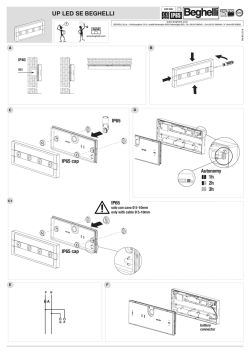
MW range adjustment (Figure 5)
7KH 0: UDQJH FDQ EH DGMXVWHG E\ XVLQJ WKH SRWHQWLRPHWHU ORFDWHG
on the PCB. It is important to set the potentiometer to the lowest
possible setting that will still provide enough coverage for the inner
ERXQGDU\ SURWHFWHG DUHD VHH )LJXUH 7ZR PLQXWHV DIWHU DSSO\LQJ SRZHU ZDUPXS SHULRG ZDON WHVW WKH
Detector over the entire protected area to verify proper operation
RI WKH XQLW VHH )LJXUH Walk Test
OFF
(Default)
ON
SW1-2: Sens
OFF
ON
(Default)
SW1-1: LED
Jumper
DIP switch Settings
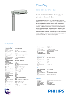
Description
Terminal
Terminal Wiring (Figure 3)
3. Verity the vertical position of the PCB on “L” (on the bottom left
side of the PCB).
6HW ',3 VZLWFK VHH ',3 VZLWFK VHWWLQJV
,QVWDOO WKH IURQW FRYHU EDFN WR LWV SODFH LQ D UHYHUVH VHTXHQFH RI
the removal).
3HUIRUP D :DON WHVW VHH :DON 7HVW VHFWLRQ
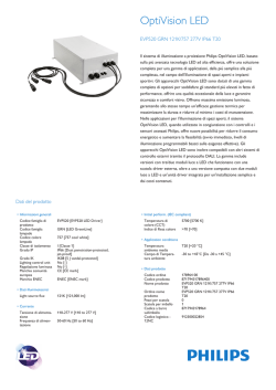
&KDQJLQJ /HQVHV VHH )LJXUH Note: %DFN WDPSHU ³%UHDNDEOH SODWH´ QRW DSSOLFDEOH LQ WKLV YHUVLRQ
0RXQWLQJ 7KH L:,6( '737 FDQ EH PRXQWHG HLWKHU RQ D ÀDW
surface or on a wall corner (corner mounting). In order to optimize
pet immunity the following guide lines are recommended:
0RXQW WKH GHWHFWRU YHUWLFDOO\ DW ULJKW DQJOHV WR WKH ÀRRU
)RU RSWLPDO SHW LPPXQLW\ PRXQW WKH GHWHFWRU DW D KHLJKW RI P
¶ ZLWK WKH 5/+ /HQV DQG P ¶ ZLWK WKH 5/37+ /HQV
0DNH VXUH DQ DQLPDO FDQQRW JHW DERYH KHLJKW RI P E\
jumping on furniture or shelving.
'R QRW PRXQW XQLW RSSRVLWH VWDLUZD\V ZKHUH DQLPDOV KDYH DFFHVV
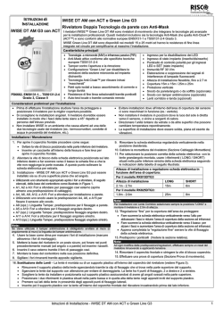
8VLQJ D VXLWDEOH WRRO RSHQ WKH IROORZLQJ NQRFNRXWV RQ WKH GHWHFWRU¶V
EDVH VHH )LJXUH Installation / Maintenance
The iWISE 811DPTP provides full pet immunity with no loss of
catch performance. The iWISE 811DTPT model easily distinguishes
between intruders and pets, allowing complete pet freedom of
movement without false alarms.
iWISE 811DTPT
E N GLIS H
Storage temperature
120 gr. (4.2 oz.)
127.6 x 64.2 x 46.6 mm
(5 x 2.5 x 1.84 in.)
Relais d'alarme N.F., 24VCC, 0,1A
ALARM
Les indicateurs LED sont activés.
Les indicateurs LED sont désactivés.
SW1-1: LED
Marche (ON)
(Défaut)
Arrêt (OFF)
Fonction
'p¿QLW OH IRQFWLRQQHPHQW GHV LQGLFDWHXUV /('
du détecteur.
Cavalier
Paramètres des DIP switch
Relais d'AP N.F., 24VCC, 0,1A
Entrée 12VCC
- 12 +
TAMPER
Description
Bornier
Câblage du Bornier (cf. Figure 3)
9pUL¿HU TXH OD SRVLWLRQ YHUWLFDOH GX 3&% HVW VXU / VXU OH F{Wp
gauche de la partie inférieure du PCB).
3DUDPpWUHU OHV ',3 VZLWFK YRLU 3DUDPqWUHV GHV ',3 VZLWFK
5HSODFH] OH FRXYHUFOH IURQWDO HQ LQYHUVDQW SRXU FHOD O
RUGUH GHV
étapes de la procédure de retrait).
6. Exécutez un test de passage (cf. Test de passage).
5HPDUTXH /D SDUWLH DPRYLEOH GX ERvWLHU DUULqUH SRXU O
$3 j
O
DUUDFKHPHQW Q
HVW SDV DSSOLFDEOH GDQV FHWWH YHUVLRQ
0RQWDJH ± O
L:,6( '737 SHXW rWUH LQVWDOOp VRLW VXU XQH VXUIDFH
plane soit en coin (gauche ou droit).
$¿Q G
RSWLPLVHU O
LPPXQLWp DX[ DQLPDX[ GRPHVWLTXHV LO HVW
recommandé de suivre les directives suivantes:
,QVWDOOH] OH GpWHFWHXU j OD YHUWLFDOH HW HQ DQJOH GURLW SDU UDSSRUW
au sol.
Pour une immunité aux animaux optimale, positionner le détecteur
j XQH KDXWHXU GH P DYHF OD OHQWLOOH 5/+ HW P DYHF OD
OHQWLOOH 5/37+
$VVXUH]YRXV TX
DXFXQ DQLPDO QH SHXW GpSDVVHU XQH KDXWHXU GH
P SDU H[HPSOH HQ VDXWDQW VXU XQ PHXEOH RX XQH pWDJqUH
1H SODFH] SDV YRWUH DSSDUHLO IDFH j GHV HVFDOLHUV DX[TXHOV GHV
DQLPDX[ GRPHVWLTXHV DXUDLHQW DFFqV
$ O¶DLGH G¶XQ RXWLO DGHTXDW RXYUH] OHV SDVWLOOHV SUé-percées
FRUUHVSRQGDQWHV VXU OD EDVH GX GpWHFWHXU FI )LJXUH Installation
Le détecteur iWISE 811DTPT procure une immunité totale aux
DQLPDX[ GRPHVWLTXHV VDQV ULHQ SHUGUH GHV SHUIRUPDQFHV GH GpWHFWLRQ
Le modèle iWISE 811DTPT fait très nettement la distinction entre les
LQWUXV HW OHV DQLPDX[ GRPHVWLTXHV SHUPHWWDQW DLQVL j FHV GHUQLHUV XQH
DEVROXH OLEHUWp GH PRXYHPHQWV VDQV SURYRTXHU GH IDXVVHV DODUPHV
iWISE 811DTPT
FRA NÇ AI S
3RZHU WR EH VXSSOLHG E\ $ PD[ 3RZHU 6RXUFH XVLQJ VDIHW\
DSSURYHG ZLUHV ZLWK D PLQ *DXJH RI $:*
Weight
Size
Physical
Filtering
White Light Protection
-10C to 55C (14F to 131F)
-20C to 60C (-4F to 140F)
Operating temperature
Optical
According to EN50130-4
24VDC, 0.1A
RF immunity
Environmental
Tamper contacts
24VDC, 0.1A
9 -16VDC***
Voltage requirements
Alarm contacts
16mA at 12VDC (Typical)
41mA at 12VDC (max.)
Current consumption
Electrical
7HFKQLFDO 6SHFL¿FDWLRQ
Fonction
Sensibilité basse.
Clignotante
(les unes après
les autres)
Allumée (ON)
Allumée (ON)
Allumée (ON)
Etat
24VCC, 0,1A
Contacts d'alarme
24VCC, 0,1A
Etat ouvert: plus de 10 ohms
Etat fermé: moins de 18 ohm
120g
127.6 x 64.2 x 46.6 mm
(5 x2.5 x 1.84 in.)
Protection anti-lumière blanche
El iWISE 811DTPT proporciona una inmunidad total frente a
animales domésticos sin perder prestaciones de detección.
(O PRGHOR L:,6( '737 GLVWLQJXH IiFLOPHQWH HQWUH LQWUXVRV
y animales domésticos, permitiendo al animal completa libertad
de movimiento, sin falsas alarmas.
iWISE 811DTPT
E S P A ÑO L
Poids
Dimensions
3K\VLTXHV
Filtrage
2SWLTXHV
Fil de diamétre au moins 0.5 mm
pour une longueur ne dépassant
pas 300 métres
Taille du càble à utiliser:
Température de stockage
IP 31/IK 02
De -10ºC à 55ºC (14ºF à 131ºF)
De -20ºC à 60ºC (-4ºF à 140ºF)
Température de fonctionnement
Indice de protection:
Selon EN50130-4
Immunité RF
Environnementales
Ondulations résiduelles maximales 0.25 créte à créte
admissibles:
Résistance de la boucle de
détection:
Contacts d'autoprotection
2.2 seconds
9 -16VCC
Tension requise
Temps minimal de changement
d'état
14.8 mA à 12VCC (en utilisation
typique)
39.5 mA à 12VCC (max. avec
tous les voyants LED allumés)
A la mise sous tension, les LEDs
clignotent les unes après les autres
MXVTX
j OD ¿Q GH OD VpTXHQFH
d'initialisation (2 à 3 min).
Indique une ALARME
Consommation électrique
(OHFWULTXHV
MIN MAX
Détection HF (hyperfréquence)
Détection IRP
Description
A Détecteur
B Couloir
6SpFL¿FDWLRQV WHFKQLTXHV
Toutes les
LEDs
Rouge
Verte
Jaune
LED
$I¿FKDJH /('
3 Réglage correct
1 Trop puissant
2 Pas assez puissant
Réglage de la portée HF (cf. Figure 5)
/H SRWHQWLRPqWUH VLWXp VXU OD FDUWH 3&% SHUPHW GH UpJOHU OD SRUWpH
GH GpWHFWLRQ K\SHUIUpTXHQFH ,O HVW LPSRUWDQW GH UpJOHU OH
SRWHQWLRPqWUH VXU OH QLYHDX OH SOXV EDV SRVVLEOH TXL IRXUQLUD
FHSHQGDQW XQH FRXYHUWXUH VXI¿VDQWH VXU OD WRWDOLWp GH OD ]RQH j
protéger.
'HX[ PLQXWHV DSUqV DYRLU UpDOLVp OD PLVH VRXV WHQVLRQ VpTXHQFH
G
LQLWLDOLVDWLRQ HIIHFWXH] XQ WHVW GH SDVVDJH SRXU YpUL¿HU O
HI¿FDFLWp
GX GpWHFWHXU VXU OD WRWDOLWp GH OD ]RQH j SURWpJHU FI )LJXUH Test de passage
Sensibilité élevée.
Arrêt (OFF)
(Défaut)
8WLOLVp SRXU Gp¿QLU OD VHQVLELOLWp GX FDQDO ,53
Marche (ON)
SW1-2: Sens
Cavalier
Descripción
Interruptor Tamper N.C.
Relé N.C.
Entrada de 12VCC
Función
LEDs apagados
LEDs encendidos
Sensibilidad Alta
Sensibilidad Baja
ON
OFF
SUHGH¿QLGR
'H¿QH OD VHQVLELOLGDG GHO FDQDO 3,5
OFF
ON
SUHGH¿QLGR
'H¿QH HO IXQFLRQDPLHQWR GH ORV /('V
B Pasillo
Encendido
Parpadeando
(sucesivamente)
Todos los
LEDs
Encendido
Encendido
Estado
Rojo
Verde
Amarillo
LED
MIN MAX
Al poner en marcha, los LEDs
parpadearán consecutivamente
KDVWD TXH ¿QDOLFH HO SHULRGR GH
calentamiento (2-3 minutos).
ALARMA
Detección MW
Detección PIR
Descripción
A Detector
Visualización de los LEDs
1 Potencia excesiva
2 3RWHQFLD ,QVX¿FLHQWH
3 Ajuste correcto
Ajuste del alcance del MW (ver Figura 5)
(O DOFDQFH GHO 0: SXHGH DMXVWDUVH PHGLDQWH HO SRWHQFLyPHWUR
situado en el PCB (placa de circuito impreso). Es importante
DMXVWDU HO SRWHQFLyPHWUR D OD FRQ¿JXUDFLyQ PiV EDMD SRVLEOH TXH
D~Q SXHGD SURSRUFLRQDU VX¿FLHQWH FREHUWXUD DO OtPLWH LQWHUQR GHO
iUHD SURWHJLGD
1. Dos minutos después de la puesta en marcha (periodo de
calentamiento), haga la prueba de movimiento al detector en
WRGD HO iUHD SURWHJLGD SDUD YHUL¿FDU HO FRUUHFWR IXQFLRQDPLHQWR
GH OD XQLGDG YpDVH )LJXUD Prueba de Movimiento
2
1
DIP
&RQ¿JXUDFLyQ GH ORV LQWHUUXSWRUHV ',3 6:
TAMPER
ALARM
- 12 +
Terminal
Cableado del Terminal (ver Figura 3)
&DPELR GH ODV /HQWHV YHU )LJXUD 6. Realice una prueba de Movimiento (ver el apartado Prueba de
Movimiento).
&LHUUH HO GHWHFWRU FRORFDQGR GH QXHYR OD WDSD GHODQWHUD
&RQ¿JXUDU ORV LQWHUUXSWRUHV ',3 YHU WDEOD PiV DEDMR
9HUL¿TXH TXH OD SRVLFLyQ YHUWLFDO GH OD 3&% HVWi SXHVWD HQ ³/´ HQ
OD SDUWH LQIHULRU L]TXLHUGD GHO FLUFXLWR LPSUHVR.
Nota: La “placa rompible” para el tamper trasero no es aplicable en
este modelo.
Usando una herramienta apropiada, abra los siguientes agujeros
SUHPDUFDGRV HQ OD EDVH GHO GHWHFWRU YHU )LJXUD 1R PRQWDU HO GHWHFWRU DSXQWDQGR KDFLD HVFDOHUDV SRU GRQGH
puedan subir los animales.
$VHJ~UHVH GH TXH XQ DQLPDO QR SXHGH VXSHUDU OD DOWXUD GH P
saltando sobre los muebles o estanterías.
3DUD XQD ySWLPD LQPXQLGDG D PDVFRWDV PRQWDU HO GHWHFWRU D
XQD DOWXUD GH P ¶ FRQ OD OHQWH 5/+ \ D P ¶ FRQ
OD OHQWH 5/37+
0RQWDU HO GHWHFWRU YHUWLFDOPHQWH HQ iQJXOR UHFWR FRQ UHVSHFWR
al suelo.
1. Montaje - El iWISE 811DTPT puede montarse HQ XQD VXSHU¿FLH
plana o en un rincón de pared (montaje en rincón).
$ ¿Q GH RSWLPL]DU OD LQPXQLGDG D DQLPDOHV GRPpVWLFRV VH
recomiendan las siguientes normas:
Instalación / Mantenimiento
9 -16VCC
24VCC, 0.1A
24VCC, 0.1A
Requisitos de voltaje
Contactos de Alarma
Contactos de Tamper
-20ºC a 60ºC (-4F a 140F)
Temperatura de almacenamiento
120 gr. (4.2 oz.)
Peso
Ingresso di alimentazione 12V
Relé N.C.
Interruttore N.C.
- 12 +
ALARM
TAMPER
ON (Default)
SW1-1: LEDS
Microint./Pontic.
I LED sono abilitati
Usato per abilitare o disabilitare il
funzionamento dei LED.
Funzione
Predisposizione Microinterruttori e Ponticelli
Descrizione
Morsetto
Cablaggio Morsettiera (vedere Figura 3)
9HUL¿FDUH OD SRVL]LRQH YHUWLFDOH GHOOD VFKHGD HOHWWURQLFD VX /
(sul lato sinistro in basso della scheda elettronica).
,PSRVWDUH L PLFURLQWHUUXWWRUL YHGL LPSRVWD]LRQH GHL
microinterruttori).
5LPRQWDUH LO FRSHUFKLR IURQWDOH H VWULQJHUH OD YLWH GL EORFFR
coperchio.
6. Effettuare una prova di copertura (Sezione Prova di movimento).
6RVWLWX]LRQH GHOOH /HQWL YHGHUH )LJXUD Nota: 1RQ q DSSOLFDELOH LQ TXHVWD YHUVLRQH LO WDPSHU DQWLULPR]LRQH
WUDPLWH OD OLQJXHWWD SRVWD VXOOD EDVH GHO FRQWHQLWRUH
1. Installazione - iWISE 811DTPT può essere installato sia su di
XQD VXSHU¿FLH SLDQD FKH DG DQJROR
Per ottimizzare la discriminazione degli animali seguire
rigorosamente le seguenti regole:
,QVWDOODUH LO ULYHODWRUH YHUWLFDOPHQWH DOOD FRUUHWWD angolazione
riferita al pavimento.
Per una corretta immunità agli animali montare il rivelatore
DG XQ DOWH]]D GL P FRQ OD OHQWH 5/+ H P FRQ OD
OHQWH 5/37+
$VVLFXUDUVL FKH O
DQLPDOH QRQ SRVVD VXSHUDUH O
DOWH]]D GL
P VDOWDQGR VX PRELOL R PHQVROH
1RQ PRQWDUH O
XQLWj GL IURQWH D VFDOH LQWHUQH DFFHVVLELOL
GDOO
DQLPDOH
Utilizzando uno strumento appropriato aprire i fori a sfondare, di
seguito elencati, della base del contenitore come illustrato in
)LJXUD Installazione / Manutenzione
iWISE 811DTPT è un rivelatore che discrimina gli animali domestici
garantendo una ottima rilevazione degli intrusi. Tramite algoritmi
proprietari e lenti appositamente progettate iWISE 811DTPT
discrimina gli impulsi infrarossi generati dagli animali domestici
LJQRUDQGR TXHVWL VHJQDOL H JHQHUDQGR O
DOODUPH VROR LQ FDVR LQ FXL
O
DUHD SURWHWWD VLD VWDWD YLRODWD GD XQ LQWUXVR 4XHVWR ULYHODWRUH
SHUPHWWH GL LQVHULUH O
LPSLDQWR G
DOODUPH SXU DYHQGR XQ DQLPDOH
domestico in casa evitando di generare allarmi impropri.
iWISE 811DTPT
I TA LI A N O
127.6 x 64.2 x 46.6 mm
(5 x 2.5 x 1.84 pul)
Tamaño
Físicas
Filtrado
Protección contra luz blanca
-10ºC a 55ºC (14F a 131F)
Temperatura de funcionamiento
Óptica
Según EN50130-4
Inmunidad a RF
Ambientales
16mA a 12VCC (Típico)
41mA a 12VCC (Máx.)
Consumo de corriente
Eléctricas
(VSHFL¿FDFLRQHV 7pFQLFDV
Funzione
Bassa sensibilità
Alta sensibilità
Utilizzati per determinare la sensibilità del
Canale PIR
I LED sono disabilitati. Non è possibile
alcun controllo remoto.
24V−, 0.1A
24V−, 0.1A
Secondo EN50130-4
da -10ºC a 55ºC
da -20ºC a 60ºC
Contatti Tamper
Immunità RF
Temp. funzionamento
Temp. stoccaggio
120 gr.
Peso
0RQWDJHP 2 L:,6( '737 &RP $&7 *UHHQ /LQH SRGH VHU
montado numa superfície plana ou num canto da parede
(montagem de canto).
$ ¿P GH RSWLPL]DU D LPXQLGDGH D DQLPDLV GH SHTXHQR SRUWH DV
VHJXLQWHV GLUHWLYDV VmR UHFRPHQGDGDV
0RQWH R GHWHFWRU YHUWLFDOPHQWH HP kQJXORV UHWRV HP UHODomR
DR FKmR
3DUD RWLPL]DU D LPXQLGDGH D DQLPDLV GH SHTXHQR SRUWH PRQWH
R VHQVRU D XPD DOWXUD GH P ¶´ FRP D OHQWH 5/+ H
P FRP D OHQWH 5/37+
,QVWDODomR 0DQXWHQomR
2 L:,6( '737 SURSRUFLRQD FRPSOHWD LPXQLGDGH D DQLPDLV GH
SHTXHQR SRUWH VHP SUHMXt]R QR GHVHPSHQKR GH FDSWXUD 2 PRGHOR
iWISE 811DTPT distingue facilmente entre intrusos e animais de
SHTXHQR SRUWH SHUPLWLQGR DRV DQLPDLV FRPSOHWD OLEHUGDGH GH
movimento, sem falsos alarmes.
iWISE 811DTPT
P ORTUG UÊ S
127.6 x 64.2 x 46.6 mm
Dimensioni
Fisiche
Filtro
Ottica
Protezione contro le luci bianche
da 9V− a 16V−
Alimentazione richiesta
Contatti di allarme
Ambientali
16mA a 12V− (Nominale)
41mA at 12V− (Massimo)
All’alimentazione tutti i LED
ODPSHJJLDQR LQ VHTXHQ]D ¿QR
DOOD ¿QH GHO SHULRGR GL
preriscaldamento (2-3 minuti).
ALLARME
Rilevazione del canale MW
Assorbimento di corrente
Elettriche
MIN MAX
Rilevazione del canale PIR
Descrizione
A Rivelatore
B Corridoio
Lampeggiante
(consecutivamente)
Illuminato
6SHFL¿FKH 7HFQLFKH
Tutti i
LED
Rosso
Illuminato
Illuminato
Giallo
Verde
Stato
LED
LED Stato Descrizione
1 Regolazione Bassa
2 Regolazione corretta
3 Regolazione Alta
Regolazione Portata MW (vedere Figura 5)
/D SRUWDWD GHOOD PLFURRQGD YD UHJRODWD WUDPLWH O¶DSSRVLWR
potenziometro situato sulla scheda elettronica. Regolare il
potenziometro della microonda al minimo possibile riferito
all’area da proteggere.
1. Due o tre minuti dopo aver alimentato il rivelatore
(preriscaldamento) effettuare la prova di copertura dell’area da
SURWHJJHUH YHUL¿FDQGR OD ULVSRVWD GHO ULYHODWRUH WUDPLWH
O¶DFFHQVLRQH GHL /(' YHGHUH )LJXUD Prova di movimento (Walk Test)
OFF (Default)
ON
SW1-2 sens
OFF
Microint./Pontic.
LEDs estão desativados.
LEDs estão habilitados, permitindo o controle do
LED através do Terminal de Entrada do LED
Usado para determinar a operação dos LEDs do
detector.
Baixa sensibilidade
OFF
(Predeterm.)
Aceso
Aceso
Aceso
Piscando
(sucessivamente)
Verde
Vermelho
Todos os
LEDs
'HVFULomR
24VDC, 0.1A
Contatos de alarme
-10C a 55C (14F a 131F)
-20C a 60C (-4F a 140F)
Temperatura de operação
Temperatura de armazenamento
Filtragem
Proteção contra luz branca
De acordo com EN50130-4
Imunidade a RF
Ótica
24VDC, 0.1A
Contatos de Tamper
Ambientais
Consumo de Corrente
16mA a 12VDC (Típico)
41mA a 12VDC (Máx.)
9 -16VDC
Ao conectar, os LEDs piscarão
FRQVHFXWLYDPHQWH DWp R ¿QDO GR
período de aquecimento (2-3
PLQXWRV $R ¿QDO GR SHUtRGR GH
aquecimento, o LED VERMELHO
FRQWLQXDUi SLVFDQGR DWp R ¿QDO
da iniciação do AM.
ALARME
Detecção no Microondas
Detecção de Infravermelho
Passivo
MIN MAX
Requisitos de voltagem
Elétricas
(VSHFL¿FDo}HV 7pFQLFDV
Estado
Amarelo
A Detector
B Corredor
LED
9LVXDOL]DomR GRV /('V
1 Energia em excesso
2 Energia fraca
3 Ajuste correto
Ajuste do Alcance do Microondas (ver Figura 5)
120 gr. (4.2 oz.)
Peso
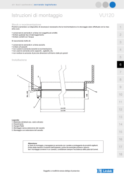
Figure 1.
Back cover - Knockouts
U.S.A Tel: +1-631-719-4400
E-mail: [email protected]
BELGIUM Tel: +32-2522-7622
E-mail: [email protected]
FRANCE Tel: +33-164-73-28-50
E-mail: [email protected]
SPAIN Tel: +34-91-490-2133
E-mail: [email protected]
ITALY Tel: +39-02-66590054
E-mail: [email protected]
UK Tel: +44-161-655-5500
E-mail: [email protected]
Range
Adjustment Bolt
Thread
ISRAEL Tel: +972-3-963-7777
E-mail: [email protected]
POLAND Tel: +48-22-500-28-40
E-mail: [email protected]
SINGAPORE Tel: + 65-66222388
E-mail: [email protected]
CHINA (Shenzhen)
Tel: +86-755-82789285
E-mail: [email protected]
CHINA (Shanghai)
Tel: +86-21-52-39-0066
E-mail: [email protected]
BRAZIL Tel: +55-11-3661-8767
E-mail: [email protected]
RISCO Group is committed to customer service and product support. You can
contact us through our website (www.riscogroup.com) or at the following telephone
and fax numbers:
RISCO Group Contacting Info
CAUTION: risk of explosion if battery is replaced by an incorrect type.
Dispose of used batteriess according to local regulations.
WARNING: This product should be tested at least once a week.
5,6&2 *URXS DQG LWV VXEVLGLDULHV DQG DI¿OLDWHV ("Seller") warrants its products to
be free from defects in materials and workmanship under normal use for 24
months from the date of production. Because Seller does not install or connect the
product and because the product may be used in conjunction with products not
manufactured by the Seller, Seller cannot guarantee the performance of the
security system which uses this product. Seller's obligation and liability under this
warranty is expressly limited to repairing and replacing, at Seller's option, within a
reasonable time after the date of delivery, any product not meeting the
VSHFL¿FDWLRQV 6HOOHU PDNHV QR RWKHU ZDUUDQW\ H[SUHVVHG RU LPSOLHG DQG PDNHV
QR ZDUUDQW\ RI PHUFKDQWDELOLW\ RU RI ¿WQHVV IRU DQ\ SDUWLFXODU SXUSRVH ,Q QR FDVH
shall seller be liable for any consequential or incidental damages for breach of this
or any other warranty, expressed or implied, or upon any other basis of liability
whatsoever.
Seller's obligation under this warranty shall not include any transportation charges
or costs of installation or any liability for direct, indirect, or consequential damages
or delay. Seller does not represent that its product may not be compromised or
circumvented; that the product will prevent any personal injury or property loss by
EXUJODU\ UREEHU\ ¿UH RU RWKHUZLVH RU WKDW WKH SURGXFW ZLOO LQ DOO FDVHV SURYLGH
adequate warning or protection. Seller, in no event shall be liable for any direct or
indirect damages or any other losses occurred due to any type of tampering,
whether intentional or unintentional such as masking, painting or spraying on the
lenses, mirrors or any other part of the detector. Buyer understands that a
properly installed and maintained alarm may only reduce the risk of burglary,
UREEHU\ RU ¿UH ZLWKRXW ZDUQLQJ EXW LV QRW LQVXUDQFH RU D JXDUDQW\ WKDW VXFK HYHQW
will not occur or that there will be no personal injury or property loss as a result
thereof. Consequently seller shall have no liability for any personal injury, property
damage or loss based on a claim that the product fails to give warning. However,
if seller is held liable, whether directly or indirectly, for any loss or damage arising
under this limited warranty or otherwise, regardless of cause or origin, seller's
maximum liability shall not exceed the purchase price of the product, which shall
be complete and exclusive remedy against seller. No employee or representative
of Seller is authorized to change this warranty in any way or grant any other
warranty.
RISCO Group Limited Warranty
127.6 x 64.2 x 46.6 mm
(5 x 2.5 x 1.84 pol.)
Tamanho
Físicas
Back tamper
“Breakable” plate Not applicable in this version
'RLV PLQXWRV GHSRLV GH DWLYDU SHUtRGR GH DTXHFLPHQWR
FDPLQKH SDUD WHVWDU R 'HWHFWRU DWUDYpV GH WRGD D iUHD SURWHJLGD
SDUD YHUL¿FDU D FRUUHWD RSHUDomR GD XQLGDGH YHU )LJXUD 2 DOFDQFH GH 0LFURRQGDV GHYH VHU DMXVWDGR XVDQGRVH R
SRWHQFL{PHWUR TXH HVWi ORFDOL]DGR QR 3&% e LPSRUWDQWH FRORFDU
R SRWHQFL{PHWUR QD FRQ¿JXUDomR PDLV EDL[D SRVVtYHO TXH DLQGD
SRVVD SURSRUFLRQDU VX¿FLHQWH FREHUWXUD SDUD WRGD D iUHD SURWHJLGD
Importante: $V GLVWkQFLDV SRGHP YDULDU GH DFRUGR FRP DV
FRQGLo}HV WpUPLFDV DPELHQWDLV
Prova de Movimento
Alta sensibilidade
ON
SW1-2
'H¿QH D VHQVLELOLGDGH GR GHWHFWRU
Sensibilidade Infravermelho Passivo
OFF
ON
(Predeterm.)
SW1-1: LED
Jumper
)XQomR
Chave do tamper N.F.
Relé N.F.
Entrada de 12VDC
'HVFULomR
Ajustes dos Dipswitch’s
TAMPER
ALARME
- 12 +
Terminal
7HUPLQDLV GH )LDomR YHU )LJXUD $VVHJXUH TXH D SRVLomR YHUWLFDO GD 3&% HVWi QD PDUFD ³/´ QD
SDUWH LQIHULRU HVTXHUGR GD 3&%
$MXVWH DV FKDYLQKDV GR ',3 VZLWFK REVHUYH R $MXVWH GRV ',3 VZLWFK
5HFRORTXH D WDPSD GLDQWHLUD HP VHX OXJDU QD VHTrQFLD FRQWUiULD
j GD UHPRomR
5HDOL]H XPD SURYD GH &DPLQKDGD YHU D VHomR 3URYD GH &DPLQKDGD
7URFD GH /HQWHV YHU )LJXUD Nota: 9ROWDU DGXOWHUDU TXHEUiYHO FKDSD QmR VH DSOLFD D HVWD YHUVmR
$VVHJXUH VH GH TXH XP DQLPDO QmR SRVVD FKHJDU DFLPD GD
DOWXUD GH P ¶ VDOWDQGR HP PyYHLV RX SUDWHOHLUDV
1mR PRQWH R DSDUHOKR HP IUHQWH D GHJUDXV DRV TXDLV R DQLPDO
pode ter acesso.
Usando uma ferramenta apropriada, abra os seguintes furos
SUpPDUFDGRV QD EDVH GR GHWHFWRU YHU )LJXUD TAMPER
Cut
Corners
Lens
8
6
4
2
0
2
4
6
8
0
0
10
2
1
4
2
10
4
A
20
6
TOP VIEW
2
TOP VIEW
Figure 5.
MW range adjustment
Meters 0
Feet
0
30
20
10
0
10
20
6
4
2
0
2
4
6
Meters
Feet
Fe e t
30
20
10
0
10
Fe e t
20
8
30
3
30
40
90°
8 10 11
20
6
90°
0
0
2
4
2
B
0
0
Meters
Feet 0
0
10
4
Meters 0
Feet
0
Fe e t
20
10
Fe e t
20
10
4
2
10
4
20
6
SIDE VIEW
2
SIDE VIEW
8
20
6
30
10 11
8
Short Pin
(Facing upwards)
Figure 4.
iWISE 811DTPT Lenses and Microwave Range
+ 12 -
12VDC
ALARM
Sleeve
Figure 2.
Lens Replacement
Figure 3.
Terminal Wiring
RL 108PTH
RL 111H
40
30
© Copyright 2026 Paperzz