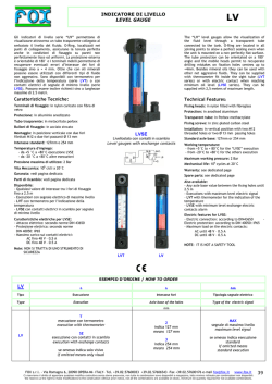
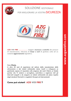
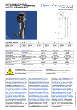
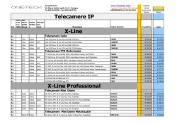
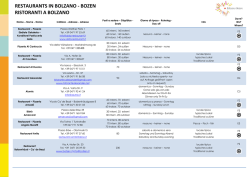
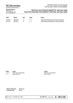
DC Inverter R410A
Sistemi per la climatizzazione
MANUALE D’USO
FreeDom OUTDOOR
D.24M2INViFeel - D.32M3INViFeel
D.34M4INViFeel - D.46M5INViFeel
D.24M2INViFeel - D.32M3INViFeel - D.34M4INViFeel - D.46M5INViFeel
FreeDom
D.24M2INViFeel - D.32M3INViFeel
D.34M4INViFeel - D.46M5INViFeel
DC Inverter R410A
Leggere questo manuale prima di procedere all’uso, e conservarlo con cura come riferimento.
In linea con la politica aziendale di continuo miglioramento dei prodotti, le caratteristiche estetiche, le dimensioni, i dati tecnici
e gli accessori di queste apparecchiature potrebbero cambiare senza preavviso.
1 - CONFORMITA’
Il condizionatore che avete acquistato è conforme alle seguenti direttive europee:
•
Basso voltaggio 73/26/EEC
•
Compatibilità elettromagnetica 89/336/EEC
Prima di procedere con qualsiasi operazione, leggere attentamente questo manuale e conservarlo con cura per consultazioni.
THE INSTRUCTIONS BEFORE USE
Usare il condizionatore solo come indicato in questo libretto di istruzioni. Queste istruzioni non coprono ogni possibile
condizione e situazione. Buon senso e cautela sono sempre raccomandati per l’installazione, uso e manutenzione,
come per ogni applicazione elettrica casalinga.
2 - ISTRUZIONI PRIMA DELL’USO
WARNING
When
having
a burning smell BEFORE USE
THE
INSTRUCTIONS
The power supply must adopt
.
1
In caso di odore di bruciato
o fumo, please
togliere turn
l’alimentazione
e contattarethe
il centro
servizi.
or smoke,
off the power
special
circuit that with air switch
Se l’anomalia persiste, l’unità potrebbe essere danneggiata e potrebbe causare corto circuiti o incendi.
supply and contact with the service
center .
protection and assure it has enough
capacity. The unit will be turned on or
WARNING
N
cables
cable a
damage
off according to your requirement
When having a burning smell
The power
supply
automatically, please
do not
turn must
on adopt
or smoke, please turn off the power
the
special
circuit
that
with
or turn off the unit frequently, otherwiseair switch
protection
it has enough
supply and contact with the service
disadvantage
effect and
mayassure
be caused
2.
L’alimentazione deve prevedere
un switch di
protezione
perunit
isolare l’impianto
elettrico
assicurandosi
abba-on or
capacity.
The unitche
will abbia
be turned
to
the
unit.
If the abnormity
still
exists,
the
center del
. prodotto.
stanza capacitàBEFORE
per supportare
i consumi
THE INSTRUCTIONS
USE
GENERAL
INFORMATION
off
according
to
your
requirement
mayo be
damaged,
may cause
L’unità potrà essere accesa
spenta
in base and
alle vostre
richieste; non spegnere e accendere l’unità frequentemente,
automatically, please do not turn on
altrimenti essa subirà danneggiamenti.
electric shock or fire.
.
3
WARNING
or turn off the unit frequently, otherwise
Mai scollegare o tagliare i caviPower
elettricimust
di potenza
e di
controllo.
adopts
the
special
Disconnect
the power
if caused
★ Ne
disadvantage
effectsupply
may be
Nel caso in cui fossero danneggiati, sarà necessario farli riparare da professionisti.
circuit to Ifprevent
fire.
long putting
air conditioner out of
use th
to thethe
unit.
the abnormity
still exists, the unit
Never cut off or damage power
The power supply must adopt
may be damaged, and may causeuse.
appoin
or smoke, please turn off the power
cables and control wires. If the power
the special circuit that with air switch
electric shock or fire.
protection and assure it has enough
cable and signal control wire were
supply and contact with the service
capacity.
The must
unit will
be turned
on or
damaged,
change them
by professional
Power
adopts
the
special
Disconnect
the power
supply if
center .
4.
L’alimentazione deve prevedere off
circuiti
specifici per
incendi.
according
to prevenire
your requirement
circuit
to oprevent
long putting the air conditioner out of
Altrimenti potrebbero verificarsi corto
circuiti
incendi.fire.
automatically, please do not turn on
use.
or turn off the unit frequently, otherwise
When having a burning smell
disadvantage effect may be caused
Otherwise, it can cause electric
Otherwise, the accumulated dusts
to the unit.
If the abnormity still exists, the unit
may cause overheating or fire.
shock or fire.
may be damaged, and may cause
★ When cleaning, it is necessary
electric shock or fire.
Rated voltage of this airconditioner
2
Otherw
fire.
D
to stop driving and turn off the
by yo
220-240V~50Hz,The compressor
Power must adopts the special
Disconnect the power supply if
★ Never damage the electric wire or
power supply.
Otherwise, it can cause electric will vibrate
Otherwise,
sharply ifthe
theaccumulated
voltage is dusts
5.to prevent
Togliere
l’alimentazione nel caso long
in cui putting
il condizionatore
non venga utilizzato
lungothe
tempo.
circuit
fire.
the air conditioner
out of per use
electric wire which is not
too low,may
resulting
damage to or fire.
causeinoverheating
shock causare
or fire. surriscaldamento
Altrimenti l’accumulo di polvere potrebbe
o incendio.
Cut off power supply
use.
appointed.
refrigerating system. Electrical
★ When cleaning, it is necessary
Rated
of this ifairconditioner
component are
easyvoltage
to damage
to stop driving and turn off the
220-240V~50Hz,The compressor
the voltage is too high.
power supply.
will vibrate sharply if the voltage is
The w
too low, resulting in damage to
Cut off power supply
shock
refrigerating system. Electrical
Otherwise, it may cause electric
servic
shock or damage.
component are easy to damage if
Otherwise, it can cause electric
Otherwise, the accumulated dusts
Otherwise, it will cause overheating or
the voltage is too high.
maynote
cause
overheating
fire.
Don't
step on the top of the outdoor unit
shock or fire.
Please
whether
the installed or fire.
or place something on it.
eart
★ When cleaning, it is necessarystand is firm enough or not.
Don't attempt to repair the air conditioner
disadvantage effect may be caused
to the unit.
WARNING
The power supply must adopt
electric
shock
or fire. with the service
supply
and contact
center
Power. must adopts the special
cut offfire.
or damage power
circuitNever
to prevent
THE
INSTRUCTIONS
cables and control wires. If the power
the
special
circuit that with BEFORE
air switch USE
protection
and the
assure
it has
enough
cable
and
signal the
control
wirewire
were
Disconnect
power
supply
if
Never
damage
electric
or
★
capacity. The unit will be turned on or
damaged,
change
them
by
professional
long putting
the
conditioner
outelettrici
of
use the
wireadatti.
which
is not
6.
Mai air
danneggiare
i cavi
o usare
elettrici
non
Ifcavi
theelectric
abnormity
still
exists,
the unit
off according
to your
requirement
Altrimenti
questo
causerebbe surriscaldamento o incendi.
may be damaged, and may cause
use.
appointed.
automatically, please do not turn on
electric
shock or
fire. must adopt
When having a burning smell
The power
supply
or turn off the unit frequently, otherwise
or smoke, please turn off the power
the special circuit that with air switch
disadvantage effect may be caused
Power must adopts the special
protection
and assure it has enough
and contact with the service
tosupply
the unit.
Otherwise,
can cause
circuit toitprevent
fire. electric
capacity. The unit will be turned on or
center .
shock or fire.
off according to your requirement
WARNING
protection and assure it has enough
cable and signal contro
capacity. The unit will be turned on or
damaged, change them by
D’USO
Disconnect the power supply if
Never damage
the elec
★MANUALE
off according to your requirement
FreeDom
long
putting the air
conditioner
automatically,
please
do notout
turnof on use the electric wire which
GENERAL INFORMATION
use.
or turn off the unit frequently, otherwise appointed.
disadvantage effect may be caused
to the unit.
Never cut off or damage power
cables and control wires. If the power
Disconnect the power supply if
cable and signal
control wire
were
Otherwise,
the the
accumulated
dusts
long putting
air conditioner
out of
damaged, change them by professional
may
cause
overheating
or
fire.
use.
★ Never damage the e
Otherwise,
will cause
use the itelectric
wireove
w
fire.appointed.
automatically,
please itdois necessary
not turn on
★ When cleaning,
Rated voltage of this airconditioner
Otherwise, the accumulated dusts
Otherwise, it will cause overheating or
powerlasupply
if
Never
damage
the
or
or
off
the
frequently,
to
stop
driving
and
turnelectric
offotherwise
thewire
★turn
7. Disconnect
Mentrethe
si effettua
pulizia dell’apparecchiatura,
èunit
necessario
togliere
l’alimentazione
al prodotto.
220-240V~50Hz,The
compressor
may cause
overheating
or fire.
fire.
Altrimenti
potrebbero
verificarsi
circuiti
oelectric
danni
similari.
disadvantage
effect
be is
caused
power
supply.
long putting
the air conditioner
out of corto
use
the
wiremay
which
not
will vibrate sharply if the voltage is
to
the unit.
If the abnormity still exists, the unit
too low, resulting in damage to
use.
appointed.
Don't attempt to repair theCutair
conditioner
Rated voltage of this airconditioner
off power
supply
may be damaged, and may cause
refrigerating system. Electrical
by yourself.
220-240V~50Hz,The compressor
electric shock or fire.
component
are
easy
to damagedusts
if
Otherwise,
it
can
cause
electric
Otherwise,
the
accumulated
will vibrate sharply if the voltage is
Don't attempt to repair the
by yourself.
too low,
resulting
in damage
to
Power
must adopts
the special
refrigerating
system.
Electrical
circuit to prevent fire.
fire.
The wrong repair will lead to a
Don't
to repairc
shock or
fire, attempt
so you should
by yourself.
service center to repair.
Disconnect
shock
or fire. the power supply if
the
voltage
is too
high.
cause
overheating
or wire
fire. or
Never
damage
the electric
★may
long putting the air conditioner out of
electric wire which is not
★ When cleaning, it is necessary use theRated
voltage of this airconditioner
use.
to220-240V
stop driving
and
turn off
thevibrerà inappointed.
8.
Il voltaggio di questo condizionatoreOtherwise,
è
il cause
compressore
caso
di voltaggio troppo basso,
it50Hz,
may
electric
220-240V~50Hz,The
compressor
the
voltage is
toorefrigerando
high.
non
l’ambiente
elettrici
si danneggiano
facilmente se il voltaggio è troppo
Otherwise,
the
accumulated
dusts correttamente.
Otherwise,
it will cause
overheating
or
power
supply.
shock
orI componenti
damage.
will vibrate sharply if the voltage is
elevato.
The wrong repair will lead to an electric
may cause overheating or fire.
fire.
too low, resulting in damage to
Cut off the
power supply
shockPlease
or fire,
so you
shouldthe
contact
Don't step on the top of the outdoor unit
whether
installed
9.
Non cercare di riparare il condizionatore
da
soli.note
refrigerating
system.
Electrical
RatedUn’errata
può causare service
un
corto
o un
incendio,
quindi
è necessario
contattare
il centro
per
Don't
attempt
to repair
the air
conditioner
or place
something
on servizi
it.
center
to
repair.
voltage ofriparazione
this airconditioner
stand
iscircuito
firm
enough
or not.
una corretta riparazione.
component
are
easy
to
damage if
by yourself.
220-240V~50Hz,The compressor
the voltage is too high.
will
vibrate
sharply
voltageunit
is
Don't
step on
the top ifofthe
the outdoor
Earthing:the
Theaccumulated
unit must be reliably
Otherwise,
it
can
cause
electric
Otherwise,
dusts
Otherwise,
it will cause overheating or
too low,
resulting
in damage to
or place
something
on it.
earthed. The earthing cable shall
may cause overheating or fire.
fire.
shock or fire. system. Electrical
refrigerating
Otherwise,
it special
may cause
be connected
to the
earthingelectric
component
are easy to
if
it isdamage
necessary
shock
orvoltage
damage.
★ When cleaning,
device
in the
construction.
Don't attempt to repair the air conditioner
Rated
of this airconditioner
thestop
voltage
is too
high.
to
driving
and
turn off the
by yourself.
220-240V~50Hz,The compressor
Don't step on the top of the outdoor unit
The wrong
repair
lead tothe
an installed
electric
Please
notewill
whether
power
supply.
will
vibrate
sharply
if
the
voltage
is
10.
Verificare che la base di appoggio sia stabile.
or
place
something on it.
stand
is
firm
enough
or
not.
shock
or
fire, soitlamay
you
should
Nel caso in cui fosse danneggiata, potrebbe
causare
caduta
dell’
unità the
causando lesioni
o altri
alle unit
persone.
As falling
off incidenti
the outdoor
can be
Iftoo
it is damaged,
lead
tocontact
the
low,
resulting
in damage
to
Cut off power supply
service
center
to
repair.
dangerous.
fall
of the unit andsystem.
cause the
injury.
refrigerating
Electrical
component are easy to damage if
Don't
the top
ofcan
the outdoor
unit
As falling
offstep
the on
outdoor
unit
be
or place something on it.
dangerous.
Otherwise, it may cause electric
shock or damage.
component are easy to damage if
Earthing:
must be reliably
the voltage
is The
too unit
high.
earthed. The earthing cable shall
2 be connected to the special earthing
device in the construction.
If it is damaged, it may lead to the
Otherwise, it will cause o
Earthing: The unit must b
earthed. The earthing cab
be connected to the special
device in the construction
The wrong repair will lead
shock or fire, so you shou
service center to repair.
Earthing: The unit mu
earthed. The earthing
be connected to the spe
device in the construc
The wrong repair will lead to an electric
shock or fire, so you should contact the
service center to repair.
As falling off the outdoor unit can be
Don't step on the top of the outdoor unit
PleaseNon
notesedersi
whether
the installed oggetti sull’unità
1.
1
o appoggiare
dangerous.
Earthing: The unit must be reliably
fall ofesterna.
the unit and cause the injury.
or
place
something
on it. causare lesioni o altri incidenti alle persone
is firm
La caduta
potrebbero
stand
enoughdell’unità
or not. o di oggetti posti su di questa
earthed. The earthing cable shall
be connected to the special earthing
device in the construction.
As falling off the outdoor unit can be
dangerous.
2
falling offtramite
the outdoor
can bead un affidabile dispositivo di messa a terra.
If it1is
lead
to the deve essereAs
2.damaged,
Messait may
a terra:
il prodotto
collegato
il cavo unit
specifico
dangerous.
fall of the unit and cause the injury.
2
3
z Be sure to cut off the power supply before cleaning the air conditioner; otherwise electric
shock might happen.
z Wetting of- air
conditioner may
cause the risk of -electric
shock. Make sure not to wash
D.24M2INViFeel
D.32M3INViFeel
- D.34M4INViFeel
D.46M5INViFeel
your
air
conditioner
in
any
case.
FreeDom
z Volatile liquids such as thinner or gasoline will cause damage to the appearance of
air conditioner. (Only use soft dry cloth moist cloth clean the air conditioner cabinet).
z This product must not be disposed together with the domestic waste.
This product has to be disposed at an authorized place for recycling
of electrical and electronic appliances.
3 - NOMI DELLE PARTI
z
The temperature of refrigerant circuit will be high,please keep the interconnection cable away
from the copper tube.
Attenzione:
MOD GWHD(18)NK3AO
1
•
Assicurarsi di staccare l’alimentazione prima di pulire il condizionatore altrimenti potrebbero verificarsi
corto circuiti.
2
No. Description
1
2
3
Air outlet grille
Handle
Valve
•
Bagnare il condizionatore potrebbe causare il rischio di corto circuito. Non lavare il vostro condizionatore in alcun
caso.
•
Liquidi evaporanti come diluenti o benzina causano danni all’estetica dell’apparecchiatura. Usare solo panni morbidi
e asciutti per pulire la carcassa del condizionatore.
•
Il prodotto non dovrà essere smaltito insieme ai rifiuti domestici.
Il prodotto deve essere smaltito in un luogo autorizzato per il riciclaggio delle apparecchiature elettriche.
3
•
La temperatura del circuito refrigerante può raggiungere temperature molto elevate, si prega ti tenere lontani i cavi di
collegamenti elettrici dai tubi di rame.
1
MOD GWHD(21)NK3AO; GWHD(24)NK3AO
No. Description
1 Air outlet grille
2 Front side panel
3 Valve
N.
Descrizione
1
griglia d’aerazione
2
pannello frontale
3
rubinetti
2
3
Note: the above figures are only intended to be a simple
diagram of the appliance and may not correspond to the
appearance of the units that have been purchased.
GENERAL
INFORMATION
TECHNICAL DATA
Nota: le figure sono solo un semplice raffigurazione e potrebbero non corrispondere
alle unità
che sono state acquistate.
MOD
Electrical data
Electricity supply
GWHD(18)NK3AO GWHD(21)NK3AO GWHD(24)NK3AO
Fuse or air switch
Minimum power cord section
Refrigerant gas(R410A)
Size and clearance
4 - CONNESSIONI ELETTRICHE
.
1
2.
L
25
2.5
1600
220-240V~,50Hz
25
2.5
2400
25
2.5
2500
A
mm2
g
Rimuovere la copertura posta sul lato destro dell’unità esterna.
L
846
950
950
mm
Connettere i cavi sulla morsettiera come da figura assicurandosi che le linee di connessione corrispondano a quelle
P
mm
riportate sulle unità interne .
300
400
420
P
H
OUTDOOR
685
3.
Fissare il cavo di alimentazione. H
4.
Assicurarsi che i cavi siano ben fissati.
Rimettere laTEMPERATURE
copertura dei collegamenti RANGE
sul lato destro dell’unità.
UNIT5.WORKING
Maximum cooling
Minimum cooling
Maximum heating
Minimum heating
Outdoor side DB/WB(
43/26(T1)
840
840
mm
GENERAL INFORMATION
)
Lasciare almeno 3mm di distanza tra i fili di collegamento
Una connessione errata dei cavi può causare il malfunzionamento di alcuni componenti elettrici. Dopo il fissaggio
24/18
assicurarsi che
ogni singolo filo non sia in contatto con altri
18/-
-7/-8
Le tubazioni e le connessioni elettriche sull’unità esterna devono corrispondere con le rispettive unità interne
Il prodotto deve essere elettricamente installato secondo le leggi nazionali vigenti.
3
4
MANUALE D’USO
FreeDom
NECTIONS
INSTALLER
、GWHD(24)NK3FO:
D24M2INViFeel
t the right side plate of the outdoor
GWHD(18)NK3FO
Handle
ELECTRICAL CONNECTIONS
mp, connect the power connection
al at the row of connection and fix
GWHD(24)NK3GO:
tting line distributing must be
door1.unit.
terminal
line bank.
Remove
the of
handle
at the right side plate of the
at of indoor
unit.
outdoor
unit (one screw).
An all-pole disconnection switch having a contact
separation of at least 3mm in all pole should be
connected in fixed wiring.
wire
clamp.
3.by
Fixwire
power
connection wire by wire clamp.
fixed
well.
2. Remove
the cable clamp, connect the power
connection cable with the terminal at the row of
L
connection and fix the connection. The fitting line
distributing must be consistent with the indoor
unit.
terminal
of line bank. Wiring should meet
tch with
suitable
capacity,
of indoor
unit.
owingthat
table.
Air switch
Power cord
magnet
buckle
and
heating
4. Ensure
wire
has
been fixed well.
an protect the circuit-short
5. please
Install the
handle.
tion:
do not
use the
t the circuit)
Including an air switch with suitable
capacity,
L
Air switch
pleasecapacity
note the following table. Air switch
N
should
O
20A be included magnet buckle and heating
L
buckle
O
25A function, it can protect the circuit-short
and overload. (Caution: please do not use the
fuse only for protect the circuit)
nection switch having a contact
ast 3mm in Air-conditioner
all pole should be Air switch capacity
wiring. GWHD(24)NK3GO
25A
INSTALLER
To unit B
To unit A
Wrong wire connection may cause malfunction of
some electric components.After fixing cable, ensure
that leads between connection to fixed point have
some space.
connecting
The connection
pipes and the connectiong wirings
cable
of the unit A ,unit B and unit C must be corresponding to
each
To the
powerother
supply respective.
connecting
cable
The appliance shall be installed in accordance with
national wiring regulations.
Note: The above figures are only intended to be a simple
diagram of the appliance and may not correspond to the
appearance of the units that have been purchased.
GWHD(24)NK3FO
ction may cause malfunction of
D32M3INViFeel
ponents.After
fixing cable, ensure
n connection to fixed point have
Handle
Handle
pes and the connectiong wirings
nit B must be corresponding to
ive.
To unit A
ll be installed in accordance with
ulations.
To unit B
L
To unit A
are only intended to be a simple
L
e and may not correspond to the
that have been purchased.
To unit B
connecting
cable
Power cord
To unit C
connecting
cable
To the power supply
Power cord
connecting
cable
connecting
cable
L
N
L
To the power supply
connecting
cable
Outdoor unit
L
Indoor unit
5
6
5
The appliance shall be installed in accordance with
national wiring regulations.
Including an air switch with suitable capacity,
please note the following table. Air switch
D.24M2INViFeel - D.32M3INViFeel -should
D.34M4INViFeel
be included- D.46M5INViFeel
magnet buckle and heating
FreeDom
buckle function, it can protect the circuit-short
and overload. (Caution: please do not use the
fuse only for protect the circuit)
Air-conditioner
Note: The above figures are only intended to be a simple
diagram of the appliance and may not correspond to the
appearance of the units that have been purchased.
Air switch capacity
GWHD(28)NK3FO
D34M4INViFeel
25A
Handle
To unit B
To unit A
To unit C
To unit D
L
Free Match D.C.inverter Muti-variable Air Conditioner Outdoor Unit
Power cord
connecting
To the power supply
connecting
cable
connecting
cable
cable
GWHD(36)NK3AO,GWHD(36)NK3BO
connecting
cable
OUTDOOR UNIT
Outdoor unit
L
Indoor unit
HANDLING
INDOOR UNIT D
INDOOR UNIT C
INDOOR UNIT B
After having removed the packaging, check that the
D46M5INViFeel
Fig.1
GWHD(42)NK3AO
contents are
intact and complete.
The outdoor unit must always be kept upright.
OUTDOOR UNIT
INDOOR UNIT A
USER
Handling must be done by suitably equipped qualified
technical personnel using equipment that is for suitable
the weight of the appliance.
7
INDOOR UNIT E
5 INDOOR UNIT D
INDOOR UNIT C
INDOOR UNIT B
Fig.2
(5) Noise Precautions
1) The air conditioning unit should be installed where ventilation is in good condition, otherwise
the working capability of the unit would be reduced or working noise would be increased.
2) The air conditioning unit should be installed on the base frame which is stable and secure
uncouth to withstand the weight of the unit; otherwise it would incur vibration and noise.
PRIMA DELL’UTILIZZO
3) During the installation, a consideration should be taken that the produced hot air or noise
should not affect neighbors or surroundings.
Dopo aver rimosso l’imballo, controllare che i contenuti siano intatti e completi.
4) Do not stack obstacles near the air outlet of the outdoor unit; otherwise it would reduce the
working capability of the unit or increase the working noise.
L’unità 5)
esterna
essere mantenuta
in posizione
nelthe
trasporto.
In thedeve
eventsempre
of the occurrence
of abnormal
noise,idonea
pleaseanche
contact
sales agent as soon as
possible.
Accessories
for Installation
L’unità(6)
deve
essere maneggiata
da personale tecnico qualificato che usi strumenti adatti al peso dell’applicazione.
Refer to the packing list for the accessories of the indoor and outdoor units respectively.
2.2 Installation of the Outdoor Unit
(1) Precautions for the Installation of the Outdoor Unit
4
6
INDOOR UNIT A
MANUALE D’USO
FreeDom
6 - INSTALLAZIONE DELL’UNITA’ ESTERNA
6.1 - Posizione
Fissare fermamente l’unità sui relativi supporti se l’installazione è a pavimento. Se il fissaggio dovrà essere eseguito a
parete o a soffitto, assicurarsi che i relativi supporti siano ben fermi in maniera che l’unità non possa muoversi in caso
di vibrazioni o forti raffiche di vento.
TDOOR UNIT
INSTALLER
Evitare di installare l’unità esterna in luoghi poco arieggiati quindi limitati.
Evitare di installare l’unità esterna in luoghi troppo esposti alla luce del sole.
t to a flat, solid floor.
Do not install the outdoor unit where it is exposed
wall or the roof, make
6.2 - Installazione delle tubazioni
to sunlight.
ured so that it cannot
vibrations or a strong
Usare solo tubazioni adatte per la connessione dei climatizzatori con refrigerante R410A.
t in pits or air vents
Le tubazioni refrigeranti non devono superare la massima lunghezza espressa nella tabella dati.
Rivestire le tubazioni refrigeranti e i rispettivi giunti con del materiale isolante.
Stringere le connessioni utilizzando chiavi dinamometriche appropiate.
and equipment for the
t exceed the maximum
ata table.
6.3 - Installazione della pipetta di fuga per il condotto di drenaggio della condensa (per mo- delli che dispongono della pompa di calore)
d joints.
La condensa fuoriesce dall’unità esterna quando l’apparecchiatura sta operando nella modalità riscaldamento. Per non
two wrenches
disturbareworking
i vicini e per rispettare l’ambiente, è necessario installare una pipetta di fuga per con il rispettivo condotto per incanalare la condensa come dimostrato nell’immagine.
he drain hose (for
from the outdoor unit
e heating mode. In order
spect the environment,
to channel the condend rubber washer on the
rain hose to it as shown
INSTALLER
circuit can cause comconnected the indoor
nd humidity from the
mp.
rom the 2-way and 3-
m the service valve.
to the service valve.
10-15 minutes until an
as been reached.
n operation, close the
m pump coupling. Stop
urn and then close it
joints for leaks using
device.
3-way valves. Discon-
Vacuum pump
INDOOR
UNITA’
INTERNA
UNIT
Refrigerant
direction
of flow
Direzionefluid
del fluido
refrigerante
Pompa a vuoto
2-way valve
Valvola
a 2 vie
3-way valve
Valvola
a 3 vie
(6) Open
Aprirebydi1/4
1/4turn
di giro
(6)
7
Use suitable connecting pipes and equipment for the
e the unit to a flat, solid floor.
Do not R410A.
install the outdoor unit where it is exposed
refrigerant
unit on a wall or the roof, make
to sunlight.
- D.34M4INViFeel
- D.46M5INViFeel
firmly D.24M2INViFeel
secured so that -itD.32M3INViFeel
cannot
The refrigerant pipes must not exceed the maximum
of intense
vibrations or a strong
FreeDom
lengths given in the technical data table.
Lag all the refrigerant pipes and joints.
tdoor unit in pits or air vents
the connections using two wrenches working
7 - Tighten
PERDITE
in opposite directions.
L’aria umida
che rimane
nel circuito
refrigerante
può causare
Install
the drain
fitting
and the
drain hose
(for il malfunzionamento del prodotto.
Dopo with
aver connesso
l’unità
esterna ed interna, bisogna assolutamente espellere l’aria e l’umidità dal circuito refrigerante
model
heat pump
only)
usando una pompa
per il and
vuoto.
Condensation
is produced
flows from the outdoor unit
when
the
appliance
is
operating
in the heatingesterni
mode.aiInrubinetti
order
1.
Svitare e rimuovere i bocchettoni
not
to disturb neighbours and to respect the environment,
install
fitting
and a drainil bocchettone
hose to channel
thevalvola
conden2. a drain
Svitare
e rimuovere
dalla
di servizio
sate
water. Install the drain fitting and rubber washer on the
outdoor
unit
chassis
and
connect
a
drain
hose
to
it
as
shown
3.
Connettere il tubo della pompa alla valvola di servizio
in the figure.
ting pipes and equipment for the
s must not exceed the maximum
echnical data table.
t pipes and joints.
ons using two wrenches working
s.
4.
ng and the drain hose (for
only)
and flows from the outdoor unit
ating in the heating mode. In order
and to respect the environment,
drain hose to channel the condenfitting and rubber washer on the
onnect a drain hose to it as shown
5.BLEEDING
Una volta spenta la pompa del vuoto, verificare la tenuta dell’impianto tramite vacuometro, dopodiché
chiudere la
INSTALLER
manopola di collegamento isolando il vacuometro.
Humid
airAprire
left inside
refrigerant
can incause
com6.
solo athe
questo
puntocircuit
i rubinetti
senso
orario tramite una chiave a brugola verificando le tenute dei giunti trapressor malfunction.
having
connected
the indoor
mite liquidi oAfter
dispositivi
elettronici
specifici.
Si consiglia, una volta aperti completamente i rubinetti di effettuare ½ giro
and outdoor
units,anti-orario
bleed theutile
air aand
humidity from
the
in senso
salvaguardare
le guarnizioni
dei rubinetti stessi.
refrigerant
circuit using a vacuum pump.
7.
Rimettere e avvitare i bocchettoni dei rubinetti. Disconnettere il tubo della pompa vuoto
(1)
Unscrew and remove the caps from the 2-way and 38.way valves.
Rimettere e avvitare il bocchettone della valvola di servizio
(2) Unscrew and remove the cap from the service valve.
(3) Connect the vacuum pump hose to the service valve.
(4) Operate the vacuum pump for 10-15 minutes
until an
INSTALLER
absolute vacuum of 10 mm Hg has been reached.
(5) With the vacuum pump still in operation, close the
low-pressure knob on the vacuum pump coupling. Stop
the vacuum pump.
INDOOR
UNITA’
INTERNA
UNIT
(6) Open the 2-way valve by 1/4 turn and then close it
Refrigerant
direction
of flow
Direzionefluid
del fluido
refrigerante
after 10 seconds. Check all the joints for leaks using
3-way valve
Valvola
a 3 vie
liquid soap or an electronic leak device.
(7) Turn the body of the 2-way and 3-way valves. Disconnect the vacuum pump hose.
(7) Girare per
(7) Turn to open fully
Entrata
Service
aprire completamente
inlet
(8) Replace and tighten all the caps on the valves.
utile
efrigerant circuit can cause comr having connected the indoor
the air and humidity from the
vacuum pump.
the caps from the 2-way and 3-
he cap from the service valve.
ump hose to the service valve.
pump for 10-15 minutes until an
mm Hg has been reached.
mp still in operation, close the
the vacuum pump coupling. Stop
e by 1/4 turn and then close it
ck all the joints for leaks using
ronic leak device.
2-way and 3-way valves. Disconhose.
the caps on the valves.
ENANCE
Azionare la pompa fino al raggiungimento del vuoto all’interno dell’impianto (misurazione visibile sul vacuometro in
dotazione sulla pompa). Maggiore è il tempo che la pompa rimane in funzione migliore sarà l’espulsione di polveri,
umidità e aria presenti nell’impianto
(2)
(2)Turn
Girare
(8)
(8)Secure
Fissare
Pompa a vuoto
INDOOR
UNITA’
INTERNA
UNIT
8 - MANUTENZIONE
Refrigerant
direction
of flow
Direzionefluid
del fluido
refrigerante
2-way valve
Valvola
a 2 vie
3-way valve
Valvola
a 3 vie
Usare strumenti adatti per il refrigeratore
(6) Open
Aprirebydi1/4
1/4R410A
di giro
(6)
turn
Entrata
Service
inlet
utile
(7)
aprire
(7)Girare
Turn toper
open
fully
completamente
Valve cap della valvola
Cappuccio
altro refrigerante oltre al R410A
(1)Turn
Girare
(2)
(8) Secure
Fissare
(8)
(2)
(1) Turn
Girare
(7) Girare per
(7) Turn to open fully
aprire completamente
Non usare nessun
(2)
(2)Turn
Girare
(8)
(8)Secure
Fissare
Valve
cap
Cappuccio
Secure
(8) Fissare
Non usare
oli minerali per pulire l’unità
della valvola
Connect
to the
Connettere
all’
indoor
unit
unità
interna
INSTALLER
Use suitable instruments for the refrigerant R410A.
Do not use any other refrigerant than R410A.
Do not use mineral oils to clean the unit.
LATION DIMENSION DIAGRAM
8
allation must be done by trained and qualified service personnel
Pompa a vuoto
2-way valve
Valvola
a 2 vie
(6) Open
Aprirebydi1/4
1/4turn
di giro
(6)
(2)
(1) Turn
Girare
Valve
cap
Cappuccio
della valvola
Vacuum pump
6
Vacuum pump
INSTALLER
Secure
(8) Fissare
(7)
aprire
(7)Girare
Turn toper
open
fully
completamente
Valve cap della valvola
Cappuccio
(1)Turn
Girare
(2)
(8) Secure
Fissare
(8)
Connect
to the
Connettere
all’
indoor
unit
unità
interna
Do not use any other refrigerant than R410A.
MANUALE D’USO
FreeDom
Do not use mineral oils to clean the unit.
9 - DIAGRAMMA DELLE DIMENSIONI PER L’INSTALLAZIONE
ALLATION DIMENSION DIAGRAM
INSTALLER
L’installazione deve essere eseguita da personale qualificato ed affidabile seguendo le istruzioni riportate su questo
manuale.
he installation
must be done by trained and qualified service personnel with reliability according to this
manual. Contattare il centro servizi prima dell’installazione per evitare il malfunzionamento causato da un’installazione non
professionale.
ontact service center before installation to avoid the malfunction due to unprofessional installation.
Durante la movimentazione dell’unità, è necessario essere aiutati da personale qualificato.
When picking up and moving the units, you must be guidedby trained and qualified person.
Assicurarsi che rimanga lo spazio necessario intorno all’apparecchiatura.
nsure that the recommende dspace is left around the appliance.
50cm or more
Space to the cover
GWHD(18)NK3FO
30cm or above
Space to the cover
30cm or above
(Air inlet side)
200cm or above
(Air outlet side)
50cm or above
Space to the wall
10 - CONTROLLO DOPO L’INSTALLAZIONE
50cm or more
Space to the cover
GWHD(24)NK3FO
GWHD(24)NK3GO
Controllo dei prodotti.
GWHD(28)NK3FO
È l’installazione affidabile?
Problemi inerenti ad un’installazione scorretta
30cm or above
Space to the cover
30cm or o
above
L’unità potrebbe gocciolare, vibrare
fare rumore
(Air inlet side)
È stato controllata la carica del
gas?
200cm or above
(Air outlet side)
È sufficiente l’isolamento termico delle unità?
È fluido il drenaggio?
La tensione d’alimentazione coincide con i dati di targa?
Sono state installate correttamente le tubazioni?
È stata fissata in modo sicuro la messa a terra?
I modelli delle linee sono conformi alle richieste?
Potrebbe causare spiacevoli effetti di riscaldamento/raffreddamento
Potrebbe causare condensazione e gocciolamento di acqua
Potrebbe causare condensazione e gocciolamento di acqua
L’unità potrebbe rompersi o i componenti potrebbero bru50 cm or
ciarsi
ab ov e
Sp ac e to
the wa ll
L’unità potrebbe rompersi o i componenti
potrebbero bruciarsi.
Rischio di scariche elettriche
9
Ci sono ostacoli vicino all’entrata e all’uscita dell’aria delle
unità esterne e interne?
La lunghezza delle tubazioni sono idonee alla carica di gas
refrigerante?
L’unità potrebbe rompersi o i componenti potrebbero bruciarsi.
L’unità potrebbe rompersi o i componenti potrebbero bruciarsi.
Non è facile decidere la quantità di carica del refrigerante.
9
D.24M2INViFeel - D.32M3INViFeel - D.34M4INViFeel - D.46M5INViFeel
FreeDom
11 - GARANZIA
Gentile Cliente,
La ringraziamo per aver acquistato un prodotto Diloc certi che ne rimarrà soddisfatto. Qualora il prodotto necessiti di interventi
in garanzia, La invitiamo a rivolgersi al rivenditore presso il quale ha effettuato l’acquisto oppure ad uno dei nostri centri di
assistenza autorizzati dislocati nella CEE e riportati sugli elenchi telefonici e sui cataloghi dei nostri prodotti. Prima di rivolgersi
al rivenditore o alla rete di assistenza autorizzata, Le consigliamo di leggere attentamente il manuale d’uso e manutenzione.
Garanzia.
Con la presente, Diloc garantisce il prodotto da eventuali difetti di materiali o di fabbricazione per la durata di 24 mesi e copre
le sole parti di ricambio e la manodopera compreso il diritto di chiamata del tecnico dei primi 12 mesi.
Qualora durante il periodo di garanzia si riscontrassero difetti di materiali o di fabbricazione, le consociate Diloc, i Centri di
assistenza Autorizzati o i Rivenditori autorizzati situati nella CEE, provvederanno a riparare o (a discrezione della Diloc) a sostituire il prodotto o i suoi componenti difettosi, nei termini ed alle condizioni sotto indicate, senza alcun addebito per i costi di
manodopera o delle parti di ricambio. Diloc si riserva il diritto (a sua unica discrezione) di sostituire i componenti dei prodotti
difettosi o prodotti a basso costo con parti assemblate o prodotti nuovi o revisionati.
ATTENZIONE
L’intervento sarà effettuato solo in luoghi di facile e sicuro accesso, in caso contrario verranno addebitati i costi relativi. Leggere attentamente i casi di decadenza garanzia sotto riportati.
ondizioni.
C
1.
Questa garanzia avrà valore solo se il prodotto difettoso verrà presentato unitamente alla fattura di vendita o di un’attestazione del rivenditore (riportante la data di acquisto, il tipo di prodotto e il nominativo del rivenditore) accompagnata dallo scontrino fiscale.
Diloc si riserva il diritto di rifiutare gli interventi in garanzia in assenza dei suddetti documenti o nel caso in cui le informazioni ivi contenute siano incomplete o illeggibili.
2.
La presente garanzia non copre i costi e/o gli eventuali danni e/o difetti conseguenti a modifiche o adattamenti apportati al prodotto, senza previa autorizzazione scritta rilasciata da Diloc, al fine di conformarlo a norme tecniche o di
sicurezza nazionali o locali in vigore in Paesi diversi da quelli per i quali il prodotto era stato originariamente progettato
e fabbricato.
3.
La presente garanzia decadrà qualora l’indicazione del modello o del numero di matricola riportata sul prodotto siano
stati modificati, cancellati, asportati o comunque resi illeggibili.
.
4
Sono esclusi dalla garanzia:
a. Gli interventi di manutenzione periodica e la riparazione o sostituzione di parti soggette a normale usura e logorio;
b. Qualsiasi adattamento o modifica apportati al prodotto, senza previa autorizzazione scritta da parte di Diloc per potenziare le prestazioni rispetto a quelle descritte nel manuale d’uso e manutenzione;
c. Tutti i costi dell’uscita del personale tecnico e dell’eventuale trasporto dal domicilio del Cliente al laboratorio del Centro di Assistenza e viceversa, nonché tutti i relativi rischi;
d. Danni conseguenti a:
- Uso improprio, compreso ma non limitato a: (a) l’impiego del prodotto per fini diversi da quelli previsti oppure l’inosservanza delle istruzioni Diloc sull’uso e manutenzione corretti del prodotto, (b) installazione o utilizzo del prodotto non conformi alle norme tecniche o di sicurezza vigenti nel Paese nel quale viene utilizzato;
- Interventi di riparazione da parte di personale non autorizzato o da parte del Cliente stesso;
- Eventi fortuiti, fulmini, allagamenti, incendi, errata ventilazione o altre cause non imputabili alla Diloc;
- Difetti degli impianti o delle apparecchiature ai quali il prodotto fosse stato collegato.
5.
Questa garanzia non pregiudica i diritti dell’acquirente stabiliti dalle vigenti leggi nazionali applicabili, né i diritti del
Cliente nei confronti del rivenditore derivanti dal contratto di compravendita.
Servizio Assistenza Tecnica
In caso di guasto sul prodotto, fare richiesta d’intervento solo ed esclusivamente alla Naicon srl, compilando l’apposito modulo in allegato al presente manuale oppure scaricandolo direttamente dal nostro sito internet www.naicon.com all’interno
della pagina riguardante i prodotti del Brand Diloc nella sezione Service. I riferimenti per l’invio della richiesta d’intervento si
trovano all’interno del modulo stesso.
Si richiede gentilmente la compilazione del modulo in ogni suo campo per riuscire così a garantire tempistiche di intervento
sicure e veloci. In caso di errori di compilazione l’azienda Naicon non si farà carico dei costi del Servizio Tecnico non preventivati quali uscite superflue dovute a modelli, numeri di serie, errori o quanto d’altro trascritto in maniera non corretta sullo
stesso modulo.
10
MANUALE D’USO
FreeDom
INDICE
1 - CONFORMITA’
2
2 - ISTRUZIONI PRIMA DELL’USO
2
3 - NOMI DELLE PARTI
4
4 - CONNESSIONI ELETTRICHE
4
5 - PRIMA DELL’UTILIZZO
6
6 - INSTALLAZIONE DELL’UNITA’ ESTERNA
7
7
7
7
6.1 - Posizione
6.2 - Installazione delle tubazioni
6.3 - Installazione della pipetta di fuga per il condotto di drenaggio della condensa (per modelli che dispongono della pompa di calore)
7 - PERDITE
8
8 - MANUTENZIONE
8
9 - DIAGRAMMA DELLE DIMENSIONI PER L’INSTALLAZIONE
9
10 - CONTROLLO DOPO L’INSTALLAZIONE
9
11 - GARANZIA
10
11
Naicon srl Via il Caravaggio, 25 Trecella
I-20060 Pozzuolo Martesana - Milano (Italy)
Tel. +39 02 95.003.1 Fax +39 02 95.003.313
www.naicon.com e-mail: [email protected]
© Copyright 2026 Paperzz