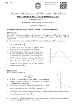
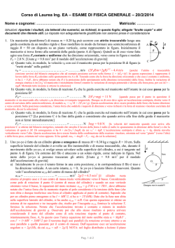
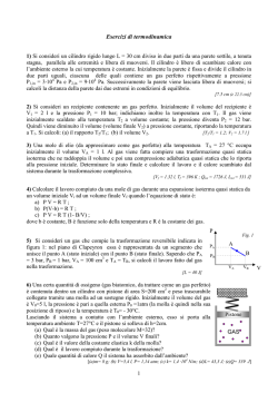
13.6
SCHEDA TECNICA/ TECHNICAL DATASHEET
VALVOLE DI RIBALTAMENTO ARATRO CON ALLINEAMENTO
DEL CARICO CON TRATTORE NEL SOLCO A DOPPIO E
SEMPLICE EFFETTO (Brevetto 2013)
TIPO / TYPE
VRAP SV
SCHEMA IDRAULICO
HYDRAULIC DIAGRAM
IMPIEGO:
Valvola realizzata per l’impiego di due cilindri in sequenza
per aratri reversibili, in modo da ottenere automaticamente
l’allineamento del carico e il suo ribaltamento. La rotazione
avviene con versoi sopra dando la possibilità di dotare l’aratro di una ruota per il traino su strada. Sono state studiate 2
differenti calibrature di passaggio in funzione del diametro
del cilindro su cui andranno montate. Per una rotazione dolce si consiglia di utilizzare sul cilindro di rotazione la valvola
a semplice effetto; se si necessita di fermare l’aratro a 90°
(punto morto), si deve utilizzare la doppio effetto.
Funzionamento: a inizio manovra parte il cilindro B di allineamento. Una volta arrivato a fine corsa parte il cilindro A
di rovesciamento e completa la rotazione. Arrivato a questo
punto il cilindro B riporta l’aratro in posizione di lavoro.
MATERIALI E CARATTERISTICHE:
Corpo: acciaio zincato
Componenti interni: acciaio temprato termicamente e rettificato
Guarnizioni: BUNA N standard
Tenuta: a cono guidato. Non ammette trafilamenti
Le valvole vengono fornite con pressione di scambio di 150
Bar: a seconda delle varie esigenze la pressione di scambio
può essere variata agendo sul regolatore di pressione.
MONTAGGIO:
Collegare C1 allo stelo e C2 al fondello del cilindro A, U1
al fondello e U2 allo stelo del cilindro B di allineamento e P
e T alle prese macchina. Data la particolare configurazione,
queste valvole possono essere montate in linea sul cilindro
idraulico o fissate direttamente alla struttura dell’aratro tramite
il foro filettato ricavato nel corpo.
REGOLAZIONI:
Le valvole vengono fornite già regolate, pertanto non devono
essere toccate. Nel caso raro se ne presentasse la necessità,
le regolazioni da eseguire sono:
•REGOLAZIONE 1: se il cilindro di allineamento (B) torna
indietro, avvitare il grano di regolazione. Se il cilindro arriva
a fine corsa e non inizia il ribaltamento, svitare il grano.
•REGOLAZIONE 2: se la valvola del cilindro A non riesce a
portare la rotazione a 90°, avvitare il grano; se la rotazione
si ferma nel punto morto (90°), svitare il grano.
•REGOLAZIONE 3: se il cilindro di allineamento (B) parte
prima che il cilindro A finisca la corsa, svitare il cappuccio e
mettere una rondella spessore 0,8 (per vite diam.5) così da
aumentare la pressione.
DOUBLE ACTING PLOUGH
OVERTURNING VALVE BY UP
MOULDBOARD LOAD SHIFTING
(Patent 2013)
USE AND OPERATION:
This valve has been designed for use on two cylinders in sequence
for reversible plough to obtain the automatic alignment of load
and its overturning. The rotation occurs with up mouldboards,
given the possibility to equip the plough of a wheel for towing on
the road. Two different passing calibrations have been studied,
depending on diameter of the cylinder, which valves will be
assembled on. For a smooth rotation is recommended to use a
single-acting valve on the cylinder used for overturning; whether it
is necessary to stop the plough at 90° (dead point), it is recommended to use the double acting one.
Operating instructions: first cylinder B starts lining up the load.
Once it got the end stroke, cylinder A starts overturning and complete the rotation. At this point cylinder B takes back the plough in
working position.
MATERIALS AND FEATURES:
Body: zinc-plated steel
Internal parts: hardened and ground steel
Seals: BUNA N standard - Poppet type: any leakage
These valves are supplied with exchange pressure at 150 bar:
according to your requirements, pressure setting can be modified
by acting on the pressure regulator.
APPLICATIONS:
Connect C1 to the stem, C2 to the cylinder’s block A, U1 to the
block and U2 to the stem of the lining up cylinder’s B; P and T to
the machine inlet. Thanks to its shape, it can be in-line assembled
on a hydraulic cylinder or directly fixed on the plough through the
threaded hole made on the body.
SETTING:
These valves are supplied already settled, therefore, should not be
touched. Nevertheless, in case of needs, settings to carry out are
as follow:
•SETTING 1: If lining up cylinder (B) comes back, screw the setting nut. If cylinder got the end stroke without starting the rotation,
unscrew the nut.
•SETTING 2: if the valve on cylinder A does not carry out the rotation at 90°, screw the nut; if rotation stops at dead point (90°),
unscrew the nut.
•SETTING 3: if lining up cylinder (B) starts before than cylinder A
got the end stoke, unscrew the cap and put a washer 0,8 mm thick
(suitable for screws with 5 mm diameter) in order to increase the
pressure.
SCHEDA TECNICA/ TECHNICAL DATASHEET
CODICE
CODE
PRESSIONE MASSIMA
DI SCAMBIO
MAX EXCHANGE
PRESSURE
Bar
SIGLA
TYPE
PRESSIONE MAX
MAX PRESSURE
Bar
V0339
VRAP 70/80 SE SV
230
400
V0340
VRAP 80/100 SE SV
230
400
V0345
VRAP 70/80 DE SV
230
400
V0346
VRAP 80/100 DE SV
230
400
13
N°1
N°1
N°2
N°2
C1 - C2
CODICE
CODE
SIGLA
TYPE
PESO
V1 - V2
L
L1
L2
L3
H
S
WEIGHT
GAS
mm
mm
mm
mm
mm
mm
Kg.
V0339
VRAP 70/80 SE SV
G 3/8”
94
58
30
142
80
80
4,760
V0340
VRAP 80/100 SE SV
G 3/8”
94
58
30
142
80
80
4,760
V0345
VRAP 70/80 DE SV
G 3/8”
94
58
30
176
80
80
4,800
V0346
VRAP 80/100 DE SV
G 3/8”
94
58
30
176
80
80
4,800
254
© Copyright 2026 Paperzz