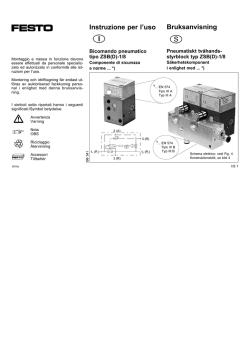
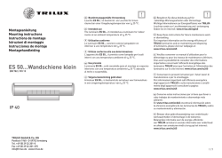
7747661 10-2011 (Tab 7) Einbauanleitung Monteringsanvisning Montering av propeller för segelbåtsdrev Montering av propeller för axel Montage des hélices sur une transmission pour voilier Montage des hélices pour arbre Istruzioni di montaggio Montaggio elica per trasmissione per barche a vela Montaggio elica per albero Einbau des Propellers für Segelbootantrieb Einbau des Propellers für Wellenantrieb Instructions de montage Instrucciones de montaje Montaje de hélice de transmisión para veleros Montaje de hélice en eje Installation of propeller for sailboat drive Installation of propeller for shaft Installation Instructions INSTALLATION INSTRUCTIONS Plus d'informations sur : www.dbmoteurs.fr VIGTIGT! IMPORTANT! Dette sæt med tilhørende monteringsvejledning er blevet udviklet for Volvo Pentas serviceværksteder, bådebyggere, maskinproducenter og andre autoriserede værksteder, som har medarbejdere med kvalificeret, faglig uddannelse. The installation instructions are only produced for professional use and are not intended for non-professional use. Volvo Penta will not assume any liability whatsoever for damage incurred, either damage to materials or personal injury, which may result if the installation instructions are not followed or if the work is carried out by non-professional personnel. Monteringsvejledningen er udelukkende beregnet til professionel anvendelse og ikke til hobby- eller fritidsbrug. Volvo Penta påtager sig intet som helst ansvar for eventuelle skader på såvel materiel som personer, som kan være en følge af at monteringsvejledningens anvisninger ikke blev overholdt, eller hvis arbejdet blev udført af ikke-professionelt personale. TÄRKEÄÄ! WICHTIG! This batch with its accompanying instructions is produced for Volvo Penta’s service workshops, boat-builders, machine manufacturers and other authorized workshops which have personnel with qualified professional training. Die Einbauanleitung ist nur für den berufsmäßigen Gebrauch vorgesehen und nicht für unprofessionelle Anwendung gedacht. Volvo Penta übernimmt nicht die geringste Haftung für irgendwelchen Schäden an Personen oder Sachen, die als Folge einer Nichtbefolgung der Einbauanleitung oder wegen Ausführung der darin beschriebenen Arbeiten durch nicht beruflich geschulte Personen entstehen. Asennusohje on tarkoitettu ainoastaan ammattikäyttöön. Volvo Penta ei vastaa mahdollisista materiaali- tai henkilövahingoista, joita asennusohjeen laiminlyöminen tai ammattitaidottoman henkilökunnan suorittama asennustyö voi aiheuttaa. Ce kit, avec instructions de montage, est destiné aux ateliers de service Volvo Penta, aux constructeurs de bateaux et autres ateliers de construction agréés avec un personnel qualifié. Les instructions de montage sont exclusivement conçues pour une utilisation professionnelle. Volvo Penta se dégage de toute responsabilité pour d’éventuels endommagements, corporels ou matériels, résultant du non respect des instructions ou d’un travail effectué par un personnel non compétent. IMPORTANTE! De montage-aanwijzing is alleen ontwikkeld voor professioneel gebruik en is niet bedoeld voor niet-professioneel gebruik. Volvo Penta neemt geen enkele verantwoordelijkheid op zich voor eventuele schade, zowel materiële schade als persoonlijk letsel, die het gevolg kan zijn als de montage-aanwijzing niet wordt gevolgd, of als het werk wordt uitgevoerd door niet-vakkundig personeel. BELANGRIJK! Deze set met de bijgevoegde montage-aanwijzing is ontwikkeld voor de werkplaatsen van Volvo Penta, botenbouwers, machinefabrikanten en overige bevoegde werkplaatsen, die personeel hebben met een gekwalificeerde vakopleiding. IMPORTANT! Tämä sarja ja asennusohje on tarkoitettu Volvo Pentan huoltokorjaamoille, veneenrakentajille, konevalmistajille ja muille valtuutetuille korjaamoille, joiden henkilökunta on saanut pätevän ammattikoulutuksen. Dieser Satz mit vorliegender Einbauanleitung ist für Volvo Penta Kundendienst-werkstätten, Werften, Maschinenbauer und für andere ermächtigte Werkstätten mit beruflich geschultem Personal vorgesehen. IMPORTANTE! Este jogo, juntamente com as respectivas instruções de montagem, foi concebido para as oficinas de serviço da Volvo Penta, construtores navais, construtores de máquinas e outras oficinas autorizadas, com pessoal devidamente formado. Las instrucciones de montaje están destinadas únicamente para uso profesional, por lo que Volvo Penta no aceptará responsabilidad alguna por cualquier daño, tanto personal como material, resultado de no haber seguido las instrucciones de montaje o de haber sido efectuado el trabajo por personal que no está debidamente capacitado. As instruções de montagem foram concebidas unicamente para utilização profissional e não se destinam a utilização não profissional. A Volvo Penta não se responsabiliza por quaisquer danos eventuais, tanto materiais como pessoais, que possam resultar no caso de as instruções de montagem não serem seguidas, ou se os trabalhos forem executados por pessoal não profissional. El presente juego con las instrucciones de montaje se destina a los talleres de servicio Volvo Penta, constructores de embarcaciones y máquinas y a otros talleres autorizados que cuentan con personal capacitado. IMPORTANTE! Questo kit e le relative istruzioni di montaggio sono stati realizzati per le officine di servizio Volvo Penta, i cantieri, i fabbricanti di macchine e tutte le altre officine autorizzate il cui personale ha ricevuto un addestramento qualificato e specializzato. VIKTIGT! Le istruzioni di montaggio sono state redatte esclusivamente per uso professionale e non sono adatte all’uso non professionale. La Volvo Penta non si assume alcuna responsabilità per eventuali danni alle cose o alle persone, derivanti da trascuratezza nel seguire le istruzioni di montaggio oppure dall’esecuzione dei lavori da parte di personale non qualificato. Denna sats med föreliggande monteringsanvisning är framtagen för Volvo Pentas serviceverkstäder, båtbyggare, maskintillverkare och övriga auktoriserade verkstäder som har personal med kvalificerad fackutbildning. ÓHMANTIKO! Ç ðáñôßäá áõôÞ ìáæß ìå ôéò ïäçãßåò ðïõ ôç óõíïäåýïõí, ðáñÜãåôáé ãéá ôá óõíåñãåßá ôçò Volvo Penta, ãéá êáôáóêåõáóôÝò óêáöþí, êáôáóêåõáóôÝò ìç÷áíçìÜôùí êáé Üëëá åîïõóéïäïôçìÝíá óõíåñãåßá ôá ïðïßá áðáó÷ïëïýí åîåéäéêåõìÝíï, êáôÜëëçëá åêðáéäåõìÝíï ðñïóùðéêü. Ïé ïäçãßåò åãêáôÜóôáóçò ðáñÜãïíôáé ìüíï ãéá åðáããåëìáôéêÞ ÷ñÞóç êáé äåí ðñïïñßæïíôáé ãéá ÷ñÞóç áðü åñáóéôÝ÷íåò. Ç Volvo Penta äåí áíáëáìâÜíåé êáìßá åõèýíç ãéá æçìßåò, åßôå óå õëéêÜ åßôå óå Üôïìá, ç ïðïßá ìðïñåß íá óõìâåß åÜí äåí ôçñçèïýí ïé ïäçãßåò åãêáôÜóôáóçò, Þ åÜí ïé åñãáóßåò äåí ãßíïõí áðü åðáããåëìáôßåò. Monteringsanvisningen är enbart framtagen för yrkesbruk och är inte avsedd för icke yrkesmässig användning. Volvo Penta påtager sig inget som helst ansvar för eventuella skador, såväl materiella som personskador, som kan bli följden om monteringsanvisningen ej följs, eller om arbetet utförs av icke yrkeskunnig personal. © Copyright 2011 AB Volvo Penta Plus d'informations sur : www.dbmoteurs.fr This page has been left blank intentionally. Diese Seite ist absichtlich leer. Ce côté est prévu pour rester vierge. Esta página se dejado en blanco intencionadamente. Pagina lasciata intenzionalmente in bianco. Denna sida är avsiktligt lämnad blank. Plus d'informations sur : www.dbmoteurs.fr General information regarding folding propellers Corrosion protection. Inspection Check the sacrificial anodes. Change the anodes when 50 % has been eroded away, or otherwise at least once per season. Remedy any lacquer damage on the drive. Replacing sacrificial anodes Folding propellers have, according to model, two or three sacrificial anodes mounted on the propeller hub. Remove the sacrificial anodes. Scrape the contact surfaces thoroughly clean. Attach the sacrificial anodes and tighten them so that a good mechanical contact is achieved. Contact with air causes oxides to form on the sacrificial anodes which impair galvanic protection. Even on brand-new sacrificial anodes an oxide layer can be present. Care of folding propellers For problem-free function and long propeller life it is important to follow these instructions carefully. Ensure that the stated tightening torques are complied with. When removing/installing it is advantageous to use a C-style wrench (fig. A 1) as a counterhold. After each season the propeller should be removed from the boat, dismantled and cleaned thouroughly. When re-installing, brush waterproof grease on all gearwheels and bearing surfaces. Check that the propeller blades can be folded easily. Important! Use zinc anodes for seawater and magnesium anodes for freshwater. Important! Always clean the sacrificial anodes before launching. Tools which contain iron, e.g. files or emery cloth, must not be used as they may impair the galvanic protection. Clean with sandpaper. A Attachment of folding propeller for sailboat drives (Figure page A) Important! Use a torque wrench and an impact hex socket. Tightening torque: 70 Nm (52 lb.ft.). Socket size = 24 mm. 2. Position the tab washer (b) on the nut so that the tabs to be folded are easily accessible. 3. Screw in the lock bolt (c). Tightening torque: 20 Nm (15 lb.ft.). 4. . Fold the three tabs on the tab washer up against the screw head so that the screw is locked in the position it is in (refer to figure). (Not all of the tabs will fit perfectly against the screw head, but they must be folded up anyway). Important! Inspect the tab washer carefully after folding to ensure no fractures have occurred. Change as necessary. 5. Brush waterproof grease on the shaft journals (d) and on the propeller blade gearwheels (e). An Allen key (6 mm), waterproof grease 828250 and assembly instructions (in plastic bag) are delivered together with the propeller. Note: Tab washer (b), see fig. A, should not be reused. Save the assembly instructions for future assembly work on the propeller. Attach the propeller according to figure page A: Fig. A:2 applies to two-bladed propellers. Fig. A:3, a:3 applies to three-bladed propellers. Fig. A:4, a:4 applies to four-bladed propellers. 1. Apply grease to the propeller shaft. Grease the shaft thoroughly. Slide the propeller boss onto the shaft. Tighten the lock nut (a). Plus d'informations sur : www.dbmoteurs.fr 7. Apply thread lock (1161053, included in hub kit) on the lock bolts (f). Screw in and tighten the lock bolts (f) with a 6 mm Allen key. Tightening torque: 10 Nm (7 lb.ft.). 8. Check that the blades have the same angle to the propeller shaft. Note! Dismantling takes place in reverse order. Important! The order is very important as the blades are balanced against each other. Incorrect assembly can lead to imbalance and vibration. 6. On three- and four-bladed propellers the blades are marked with a number; refer to figures a:3, a:4. Install the propeller blades in the propeller hub in the correct order according to fig. a, clockwise in numerical order, and push in the shaft journals (d). B Attachment of folding propeller for shaft (Figure page B) Important! Important! No grease may be used on the propeller shaft or hub when installing the shaft. 3. Apply thread lock (1161053, included in hub kit) on the lock bolts (4) and tighten them into the hub. Then apply thread lock to the lock bolt heads. 4. Brush waterproof grease on the shaft journals (5) and on the propeller blade gearwheels (6). 5. On three- and four-bladed propellers the blades are marked with a number; refer to figures a:3, a:4. Install the propeller blades in the propeller hub in the correct order according to fig. a, clockwise in numerical order, and push in the shaft journals (5). An Allen key (6 mm), waterproof grease 828250 and assembly instructions (in plastic bag) are delivered together with the propeller. Save the assembly instructions for future assembly work on the propeller. Attach the propeller according to figure page B: Fig. B:2 applies to two-bladed propellers. Fig. B:3, b:3 applies to three-bladed propellers. Fig. B:4, b:4 applies to four-bladed propellers. 1. Thoroughly wipe the propeller shaft and the hub dry. Important! Counterhold the propeller shaft with the key grip and a strong monkey-wrench and tighten the nut (3). Use a torque wrench and an impact hex socket. 6. Apply thread lock to the lock bolts (7). Screw in and tighten the lock bolts (7) with a 6 mm Allen key. Tightening torque: 10 Nm (7 lb.ft.). 7. Check that the blades have the same angle to the propeller shaft. Note: Dismantling takes place in reverse order. In order to free the propeller from the shaft a soft wooden or rubber mallet may be used. If the propeller is dificult to remove, a puller will be necessary. 2. Place the wedge (1) in the propeller shaft and then push the propeller hub onto the shaft. Install the washer (2). Important! The order is very important as the blades are balanced against each other. Incorrect assembly can lead to imbalance and vibration. Important! Tightening torque for the nut (3) is determined by by engine power, as indicated in table B:1. In column I engine power is indicated in hp(kW), and in column II the corresponding tightening torque in Nm(lb.ft.). Plus d'informations sur : www.dbmoteurs.fr Allgemeine Hinweise zu Faltpropellern Schutzanoden, auswechseln Bei Faltpropellern sind, je nach Modell, zwei oder drei Schutzanoden auf der Propellernabe angebracht. Schutzanoden ausbauen. Anliegeflächen sorgfältig abschaben. Neue Schutzanoden anbauen und so anziehen, dass guter Metallkontakt hergestellt wird. In Kontakt mit Luft bildet sich Oxid an den Schutzanoden, wodurch der galvanische Schutz verschlechtert wird. Auch auf vollkommenneuen Schutzanoden kann eine Oxidschicht vorhanden sein. Wartung von Faltpropellern Damit die Propeller störungsfrei und lange funktionieren, müssen die Anweisungen genau befolgt werden. Angegebene Anziehdrehmomente beachten. Für den Aus-/Einbau wird am besten ein ZugHakenschlüssel (Bild A:1) als Gegenhalter verwendet. Am Ende jeder Saison muss der Propeller vom Boot abgebaut, zerlegt und gründlich gereinigt werden. Beim erneuten Einbau sind alle Zähne und Lagerflächen mit wasserfestem Fett zu bestreichen. Prüfen, dass sich die Propellerflügel leicht ausklappen lassen. Korrosionsschutz. Prüfen Schutzanoden prüfen. Auswechseln, wenn 50 % des Materials zersetzt sind beziehungsweise mindestens einmal pro Saison. Etwaige Lackschäden am Antrieb beheben. Wichtig! Vor dem Zu-Wasser-Lassen stets alle Schutzanoden reinigen. Um den galvanischen Schutz nicht zu verschlechtern, keine metallhaltigen Werkzeuge wie Feile, Schmirgeltuch verwenden. Mit Sandpapier reinigen. Wichtig! In Salzwasser Schutzanoden aus Zink, in Süßwasser aus Magnesium verwenden. A Einbau des Faltpropellers eines Segelbootsantriebes (Bildseite A) 2. Faltscheibe (b) auf die Mutter setzen, sodass die Laschen, die sich falten lassen sollen, gut zugänglich sind. 3. Sicherungsschraube (c) einbauen. Anziehdrehmoment: 20 Nm. 4. Die drei Zacken der Zackenscheibe über den Schraubenkopf biegen, so dass die Schraube in ihrer befindlichen Lage festgesetzt wird, siehe Bild. (Alle Zacken passen nicht genau auf den Schraubenkopf, sind aber trotzdem aufzubiegen.) Wichtig! Drehmomentschlüssel und Sechskant-Drehmomentsteckschlüsseleinsatz verwenden. Anziehdrehmoment: 70 Nm. Schlüsselbreite = 24 mm. Zusammen mit dem Propeller werden ein Innensechskantschraubenschlüssel (6 mm), wasserfestes Fett 828250 und eine Einbauanleitung (im Kunststoffbeutel) geliefert. Achtung! Faltscheibe (b), siehe Bild A darf nicht wiederverwendet werden. Einbauanleitung aufbewahren für zukünftige Einbauarbeiten am Propeller. Propeller gemäß Bildseite A einbauen: Bild A:2 gilt für zweiflügelige Propeller. Bild A:3, a:3 gilt für dreiflügelige Propeller. Bild A:4, a:4 gilt für vierflügelige Propeller. 1. Fett auf die Propellerwelle drücken. Propellerwelle sorgfältig schmieren. Anschließend die Propellernabe auf die Welle schieben. Anschließend Sicherungsmutter (a) anziehen. Wichtig! Nach dem Falten Faltscheibe sorgfältig auf Risse prüfen. Bei Bedarf auswechseln. 5. Wasserfestes Fett auftragen auf die Lagerzapfen (d) und auf die Zähne der Propellerflügel (e). Plus d'informations sur : www.dbmoteurs.fr 7. Gewindesicherung (1161053, im Nabensatz enthalten) auf Sicherungsschrauben auftragen (f). Hineinschrauben und Sicherungsschrauben (f) mithilfe eines 6-mm-Innensechskantschlüssels anziehen. Anziehdrehmoment: 10 Nm. 8. Prüfen, dass die Flügel denselben Winkel bilden zur Propellerwelle. Achtung! Das Zerlegen verläuft in ungekehrter Reihenfolge. Wichtig! Die Reihenfolge ist sehr wichtig, da die Flügel miteinander ausgewuchtet sind. Falscher Einbau kann zu Unwuchten und Vibrationen führen 6. Bei Drei- und Vierblatt-Propellern sind die Propellerblätter mit einer Ziffer gekennzeichnet, siehe Bilder a:3, a:4. Propellerblätter in der richtigen Reihefolge in die Propellernabe einbauen, siehe Bild a, im Uhrzeigersinn ihrer Nummer nach, und Achsbolzen (d) hinein schieben. B Einbau des Faltpropellers auf einer Welle (Bildseite B) �������������������������������������������� Wichtig! Beim Einbau der Propellerwelle müssen Welle und Nabe völlig frei von Fett sein. 3. Gewindesicherung (1161053, im Nabensatz enthalten) auf Sicherungsschrauben auftragen (4). Diese in der Nabe anziehen. Anschließend Gewindesicherung auf dem Kopf der Sicherungsschrauben auftragen. 4. Wasserfestes Fett auftragen auf die Lagerzapfen (5) und auf die Zähne der Propellerflügel (6). 5. Bei Drei- und Vierblatt-Propellern sind die Propellerblätter mit einer Ziffer gekennzeichnet, siehe Bilder a:3, a:4. Propellerblätter in der richtigen Reihefolge in die Propellernabe einbauen, siehe Bild a, im Uhrzeigersinn ihrer Nummer nach, und Achsbolzen (5) hinein schieben. Zusammen mit dem Propeller werden ein Innensechskantschraubenschlüssel (6 mm), wasserfestes Fett 828250 und eine Einbauanleitung (im Kunststoffbeutel) geliefert. Einbauanleitung aufbewahren für zukünftige Einbauarbeiten am Propeller. Propeller gemäß Bildseite B einbauen: Bild B:2 gilt für zweiflügelige Propeller. Bild B:3, b:3 gilt für dreiflügelige Propeller. Bild B:4, b:4 gilt für vierflügelige Propeller. 1. Propellerwelle und Nabe gut abtrocknen. 6. Gewindesicherung auf den Sicherungsschrauben auftragen (7). Sicherungsschrauben (7) einschrauben und mithilfe eines 6-mm-Innensechskantschlüssels anziehen. Anziehdrehmoment: 10 Nm. 7. Prüfen, dass die Flügel denselben Winkel bilden zur Propellerwelle. Achtung! Das Zerlegen verläuft in ungekehrter Reihenfolge. Zum Lösen des Propellers von der Welle weichen Gummi- oder Holzschlägel verwenden. Bei festsitzendem Propeller Abzieher verwenden. Wichtig! Mit Schlüsselgriffe und kräftigem Schraubenschlüssel Propellerwelle dagegen halten. Mutter (3) mit einem Anziehdrehmoment anziehen. Drehmomentschlüssel und Sechskant-Drehmomentsteckschlüsseleinsatz verwenden. Wichtig! Die Reihenfolge ist sehr wichtig, da die Flügel miteinander ausgewuchtet sind. Falscher Einbau kann zu Unwuchten und Vibrationen führen. Wichtig! Das Anziehdrehmoment der Mutter (3) wird von der Motorleistung bestimmt und geht aus der Tabelle B:1 hervor. In Spalte I ist die Motorleistung in PS (kW) angegeben, in Spalte II das entsprechende Drehmoment in Nm (lb.ft.). Plus d'informations sur : www.dbmoteurs.fr 2. Keil (1) in die Propellerwelle setzen. Dann Propellernabe auf die Welle schieben. Scheibe (2) einbauen. Informations générales relatives aux hélices repliables Protection contre la corrosion. Contrôle Contrôler l'état des anodes sacrificielles. Remplacer les anodes si elles sont usées à plus de 50 % de leur volume d’origine, ou au moins une fois par saison. Réparer / retoucher également les dommages sur la peinture de l'embase. Important ! Par conséquent, toujours nettoyer les anodes sacrificielles avant la mise à l'eau. Ne pas utiliser d'outil en acier (par ex. lime, toile émeri ou brosse métallique), ceci risquant d'affecter la protection galvanique. Nettoyer à l'aide de papier abrasif. Remplacement des anodes sacrificielles Les hélices repliables comportent, en fonction du modèle, deux ou trois anodes sacrificielles montées sur le moyeu d’hélice. Déposer les anodes sacrificielles. Gratter et nettoyer minutieusement les surfaces de contact. Monter les nouvelles anodes sacrificielles et les serrer de manière à obtenir un bon contact mécanique. Les anodes sacrificielles s'oxydent au contact de l'air, ce qui a pour effet d'altérer la protection galvanique. Même les anodes neuves peuvent être couvertes d'une couche d'oxyde. Entretien de l'hélice repliable Il est essentiel d'observer minutieusement les instructions, afin d'assurer une fiabilité et une durée de vie optimales de l'hélice. Lors de montage/démontage, il est recommandé d’utiliser une clé à ergots (fig. A:1) comme contre-appui. Après chaque saison, il convient de déposer l'hélice du bateau, de la désassembler et la nettoyer minutieusement. Lors du remontage, appliquer de la graisse hydrofuge sur tous les engrenages et les surfaces de palier. Vérifier que les pales d'hélice se replient aisément. Important ! Utiliser des anodes sacrificielles en zinc en eau salée et des anodes au magnésium en eau douce. A Montage d'hélice repliable sur embase de voilier (page d'illustrations A) Important ! Utiliser une clé dynamométrique et la douille à six pans. Couple de serrage : 70 Nm (52 lb. pi). Pas de clé = 24 mm. 2. Placer la rondelle-frein (2) sur l'écrou, de manière à pouvoir aisément accéder aux languettes rabattables. 3. Monter la vis de blocage (3). Couple de serrage : 20 Nm (15 lb.pi). 4. Rabattre les trois languettes sur la tête de vis, de manière à bloquer le boulon dans la position où il se trouve, voir la figure. (Même si toutes les languettes ne correspondent pas parfaitement à la tête de vis, elles devront toutefois être rabattues.) Important ! Contrôle la rondelle-frein après cette opération pour vérifier qu'il n'y a pas de traces de fissures. Remplacer le cas échéant. 5. Appliquer de la graisse hydrofuge sur les axes (d) et sur les dentures des pales d'hélice (e). L'hélice est livrée avec une clé à 6 pans creux (6 mm), de la graisse hydrofuge 828250 et la notice de montage (dans le sac en plastique). N.B. La rondelle-frein (b), voir la fig. A, ne doit pas être réutilisée. Conserver la notice de montage pour toute intervention ultérieure sur l'hélice. Monter l'hélice selon la page d'illustrations A: Fig. A:2 concerne l'hélice à deux pales. Fig. A:3, a:3 concernent l'hélice à trois pales. Fig. A:4, a:4 concernent l'hélice à quatre pales. 1. Appliquer de la graisse sur le moyeu d'hélice. Graisser minutieusement l'arbre porte-hélice. Emmancher ensuite le moyeu d'hélice sur l'arbre. Serrer ensuite l'écrou de blocage (1). Plus d'informations sur : www.dbmoteurs.fr 7. Appliquer du liquide frein-filet (1161053, inclus dans le kit de moyeu) sur les vis de serrage (f). Visser et serrer les vis (f) à l'aide de la douille six pans de 6 mm. Couple de serrage : 10 Nm (7 lb.pi). 8. Vérifier que les pales forment un angle identique par rapport à l’arbre porte-hélice. N.B. La dépose s'effectue dans l’ordre inverse. 6. Sur les hélices à 3 ou 4 pales, les pales sont marquées d’un chiffre. Monter les pales d’hélice sur le moyeu d’hélice dans le sens horaire et dans l’ordre numérique, voir la fig. a, puis insérer les axes de verrouillage (d). Important ! L'ordre de montage est essentiel du fait que les pales sont équilibrées l'une par rapport à l'autre. Un ordre de montage erroné peut engendrer un déséquilibre et des vibrations. B Montage d'hélice repliable sur arbre (page d'illustrations B) Important ! Important ! Ne pas appliquer de graisse sur l’arbre porte-hélice ou sur le moyeu lors du montage de l’arbre. Important ! L'ordre de montage est essentiel du fait que les pales sont équilibrées l'une par rapport à l'autre. Un ordre de montage erroné peut engendrer un déséquilibre et des vibrations. 2. Positionner la clavette (1) dans l'arbre porte-hélice puis emmancher ensuite le moyeu d'hélice sur l'arbre. Monter la rondelle (2). 3. Appliquer du liquide frein-filet (1161053, inclus dans le kit de moyeu) sur les vis de serrage (4) puis les serrer sur le moyeu. Appliquer ensuite du liquide frein-filet sur les vis de serrage. 4. Appliquer de la graisse hydrofuge sur les axes (5) et sur les dentures des pales d'hélice (6). 5. Sur les hélices à 3 ou 4 pales, les pales sont marquées d’un chiffre. Monter les pales d’hélice sur le moyeu d’hélice dans le sens horaire et dans l’ordre numérique, voir la fig. a, puis insérer les axes de verrouillage (5). L'hélice est livrée avec une clé à 6 pans creux (6 mm), de la graisse hydrofuge 828250 et la notice de montage (dans le sac en plastique). Conserver la notice de montage pour toute intervention ultérieure sur l'hélice. Monter l'hélice selon la page d'illustrations B: Fig. B:2 concerne l'hélice à deux pales. Fig. B:3, b:3 concerne l'hélice à trois pales. Fig. B:4, b:4 concernent l'hélice à quatre pales. 1. Essuyer minutieusement l’arbre porte-hélice et le moyeu. 6. Appliquer du liquide frein-filet sur les vis de serrage (7). Visser et serrer les vis de blocage (7) à l'aide de la douille six pans de 6 mm. Couple de serrage : 10 Nm (7 lb.pi). 7. Vérifier que les pales forment un angle identique par rapport à l’arbre porte-hélice. N.B. La dépose s'effectue dans l’ordre inverse. Pour détacher l'hélice, utiliser un maillet souple en caoutchouc ou en bois. Un extracteur peut s'avérer nécessaire si l'hélice est bloquée sur son axe. Important ! Le couple de serrage de l’écrou (3) est déterminé par la puissance du moteur ; il est indiqué dans le tableau B:1. La puissance du moteur est indiquée en chevaux (kW) dans la colonne I et le couple de serrage correspondant en Nm (lb.ft.) dans la colonne II. Important ! Retenir l'arbre porte-hélice avec une robuste clé à molette et serrer l'écrou (3). Utiliser une clé dynamométrique et la douille à six pans. Plus d'informations sur : www.dbmoteurs.fr Información general sobre hélices abatibles Cambio de ánodos protectores Independientemente del modelo las hélices plegables tienen dos o tres ánodos protectores montados sobre el cubo de la hélice. Desmontar los ánodos protectores. Limpiar rascando las superficies de contacto minuciosamente. Montar los nuevos ánodos protectores y apretarlos hasta obtener un buen contacto metálico. En contacto con el aire se forma óxido en los ánodos protectores, lo que empeora la protección galvánica. En los ánodos protectores nuevos puede haber también una capa de óxido. Cuidados de la hélice abatible Para un funcionamiento óptimo y una larga vida útil de la hélice es importante seguir minuciosamente las instrucciones. Asegurarse de que se respeten los pares de apriete indicados. Como apoyo en el montaje/desmontaje puede utilizarse ventajosamente una llave fija (fig. A:1). Una vez finalizada la temporada, se deberá desmontar la hélice de la embarcación, desarmarla y limpiarla minuciosamente. Al volver a montar, aplicar grasa insoluble en todos los dientes y en todas las superficies de cojinete. Comprobar que las aspas de hélice puedan abatirse fácilmente. Anticorrosivo. Control Controlar los ánodos protectores. Sustituirlos por nuevos si el 50 % del material ha quedado eliminado, o una vez por temporada como mínimo. Corregir también los posibles daños en la pintura de la cola. Importante: Limpiar siempre antes de la botadura los ánodos protectores. No hay que utilizar herramientas que contengan acero, p. ej. limas o tela de esmeril, pues ello podría empeorar la protección galvánica. Limpiar con papel de estraza. Importante: Usar ánodos protectores de zinc para agua salada y de magnesio para agua dulce. A Montaje de hélices abatibles en colas de embarcaciones de vela (Figura A) Importante: Inspeccionar minuciosamente la arandela después de haber doblado la orejeta, para comprobar que no haya fisuras. Cambiar si es necesario. 5. Aplicar grasa hidrófuga en los muñones de eje (d) y los engranajes de las aspas de hélice (e). Plus d'informations sur : www.dbmoteurs.fr Importante: Usar una llave dinamométrica y un casquillo de fuerza hexagonal. Par de apriete: 70 Nm. Anchura de llave = 24mm. 2. Colocar la arandela (b) en la tuerca de forma que se pueda acceder fácilmente a las orejetas que deban doblarse. 3. Montar la tuerca de seguridad (c). Par de apriete: 20 Nm. 4. Doblar las tres lengüetas de la arandela de seguridad contra la cabeza del tornillo de manera que éste quede asegurado en la posición en la que se encuentra, ver figura. (No todas las lengüetas encajan perfectamente sobre la cabeza del tornillo pero, pese a ello, han de doblarse.) Juntamente con la hélice se entregan una llave Allen (6 mm), grasa hidrófuga 828250 y las instrucciones de montaje (en una bolsa de plástico). Nota: La arandela (b), ver la fig. A no debe reutilizarse. Guardar las instrucciones de montaje para futuros trabajos de montaje con la hélice. Montar la hélice según la figura A: Fig. A:2 rige para hélices de dos aspas. Fig. A:3, a:3 rige para hélices de tres aspas. Fig. A:4, a:4 rige para hélices de cuatro aspas. 1. Sacar a presión la grasa del eje de hélice. Lubricar minuciosamente el eje de hélice. Seguidamente, encajar el cubo de hélice en el eje. Seguidamente apretar la tuerca de seguridad (a). 7. Aplicar sellante bloqueador (1161053, se incluye en el kit de cubo) en los tornillos de seguridad (f). Atornillar y apretar los tornillos de seguridad (f) con una llave Allen de 6 mm. Par de apriete: 10 Nm. 8. Controlar que las aspas configuren el mismo ángulo en relación al eje de hélice. Atención: El desmontaje debe realizarse en el orden opuesto. 6. En las hélices de tres y cuatro palas estas están marcadas con una cifra, ver figuras a:3 y a:4. Montar las palas en el cubo en el orden correcto según la figura a, en sentido horario en orden numérico, e introducir los muñones de eje (d). Importante: Es muy importante el orden a seguir ya que las aspas están equilibradas entre sí. Un montaje incorrecto puede causar desequilibrio y vibraciones. B Montaje de hélices abatibles para ejes (Figura B) 2. Colocar la chaveta (1) en el eje de hélice y, a continuación, insertar el cubo de hélice en el eje. Montar la arandela (2). Importante: Es muy importante el orden a seguir ya que las aspas están equilibradas entre sí. Un montaje incorrecto puede causar desequilibrio y vibraciones. 6. Aplicar sellante bloqueador en los tornillos de seguridad (7). Atornillar y apretar los tornillos de seguridad (7) con una llave Allen de 6 mm. Par de apriete: 10 Nm. 7. Controlar que las aspas configuren el mismo ángulo en relación al eje de hélice. Nota: El desmontaje debe realizarse en el orden opuesto. Para soltar la hélice del eje, se puede usar un martillo con cabeza de goma blanda o de madera. Si la hélice está fuertemente montada, quizás deba usarse un extractor. Importante: Hacer presión sobre el eje de hélice con el agarre de llave y una llave inglesa grande y apretar la tuerca (3). Usar una llave dinamométrica y un casquillo de fuerza hexagonal. Importante: El par de apriete de la tuerca (3) viene determinado por la potencia del motor y se indica en la tabla B:1. En la columna I la potencia del motor se indica en CV (kW) y en la columna II aparece el par de apriete correspondiente en Nm (lb.ft.). Plus d'informations sur : www.dbmoteurs.fr Importante: Al montar el eje de la hélice no hay que utilizar grasa en éste y tampoco en el cubo. 3. Aplicar sellante bloqueador (1161053, se incluye en el kit de cubo) en los tornillos de seguridad (4) y apretarlos en el cubo. A continuación, aplicar sellante bloqueador en la cabeza de las tuercas de seguridad. 4. Aplicar grasa hidrófuga en los muñones de eje (5) y los engranajes de las aspas de hélice (6). 5. En las hélices de tres y cuatro palas estas están marcadas con una cifra, ver figuras a:3 y a:4. Montar las palas en el cubo en el orden correcto según la figura a, en sentido horario en orden numérico, e introducir los muñones de eje (5). Juntamente con la hélice se entregan una llave Allen (6 mm), grasa hidrófuga 828250 y las instrucciones de montaje (en una bolsa de plástico). Guardar las instrucciones de montaje para futuros trabajos con la hélice. Montar la hélice según la figura B: Fig. B:2 rige para hélices de dos aspas. Fig. B:3, b:3 rige para hélices de tres aspas. Fig. B:4, b:4 rige para hélices de cuatro aspas. 1. Limpiar minuciosamente el eje de la hélice y su cubo. Informazioni di carattere generale sulle eliche a pale abbattibili Sostituzione degli anodi sacrificali A seconda del modello, le eliche ripiegabili hanno due o tre anodi di protezione montati sul mozzo dell’elica. Controllare gli anodi sacrificali. Pulire accuratamente le superfici di contatto. Installare i nuovi anodi sacrificali e serrarli accuratamente, in modo che un buon contatto metallico sia assicurato. A contatto con l'aria si forma ossido sugli anodi sacrificali, che ne peggiore la protezione galvanica. Anche su anodi sacrificali nuovi lo strato superficiale può essere ossidato. Manutenzione dell’elica a pale abbattibili Per un funzionamento privo di problemi e una lunga durata dell'elica, è necessario seguire accuratamente le istruzioni. Accertarsi che siano rispettate le coppie di serraggio prescritte. Per il montaggio/ smontaggio è opportuno fare uso di una chiave a gancio (fig. A:1) come attrezzo di ritegno. Dopo ogni stagione estiva è consigliabile smontare l’elica dall’imbarcazione, disassemblarla e pulirla accuratamente. Al rimontaggio, spalmare uno strato di grasso su tutti gli ingranaggi e i cuscinetti. Controllare che le pale dell’elica siano facilmente abbattibili. Protezione anticorrosione. Controllo Controllare gli anodi sacrificali. Sostituirli quando il 50 % del materiale si è consumato o almeno una volta per stagione. Ritoccare anche eventuali danni alla verniciatura della trasmissione. Importante! Pulire sempre gli anodi sacrificali prima del varo dell'imbarcazione. Non utilizzare utensili che contengono ferro, come lime, tela smerigli, ecc., perché questo peggiora la protezione galvanica. Pulire con carta vetrata. Importante! Usare anodi sacrificali di zinco per l'acqua marina e di magnesio per l'acqua dolce. A Installazione dell'elica a pale abbattibili su trasmissioni per barche a vela (Lato A dell'immagine) 2. Disporre la rondella pieghevole (b) sul dado in modo da poter raggiungere facilmente le linguette che devono essere ripiegate. 3. Applicare la vite di bloccaggio (c). Coppia di serraggio: 20 Nm. 4. Sollevare le tre linguette della rondella sulla testa della vite, in modo da bloccare quest’ultima nella posizione in cui si trova; ved. fig. (Non tutte le linguette si adattano perfettamente sulla testa della vite, ma vanno comunque sollevate.) Importante! Usare la chiave dinamometrica e la bussola esagonale. Coppia di serraggio: 70 Nm. Apertura della chiave = 24 mm. Importante! Ispezionare accuratamente la rondella pieghevole dopo la piegatura, per accertarsi che non si sia spezzata. Sostituirla se necessario. 5. Spalmare grasso idrorepellente sui perni assiali (d) e sui denti delle pale abbattibili (e). Assieme all'elica vengono consegnati una chiave a brugola (6 mm), grasso idrorepellente 828250 e le istruzioni di montaggio. Nota! La rondella pieghevole (b), vedere figura A, non va riutilizzata. Conservare le istruzioni di montaggio per per i successivi lavori di montaggio dell'elica. Installare l'elica come descritto nella parte A: Fig. A:2 vale per eliche a due pale abbattibili. Fig. A:3, a:3 vale per eliche a tre pale abbattibili. Fig. A:4, a:4 vale per eliche a quattro pale abbattibili. 1. Spremere il grasso sull'albero dell'elica. Ingrassare accuratamente l’albero dell’elica. Inserire poi il mozzo nell’albero dell’elica. Serrare poi il controdado (a). Plus d'informations sur : www.dbmoteurs.fr 7. Applicare sigillante per filettature (1161053, compreso nel kit del mozzo) sulle viti di bloccaggio (f). Avvitare e serrare le viti (f) con una chiave a brugola da 6 mm. Coppia di serraggio: 10 Nm. 8. Controllare che le pale siano tutte alla stessa angolazione rispetto all'albero dell'elica. Nota! Smontare le parti in ordine inverso. 6. Le pale delle eliche a tre e a quattro pale sono marcate con una cifra; ved. fig. a:3, a:4. Montare le pale dell’elica nel mozzo secondo l’ordine corretto come da fig a, in senso orario e per ordine numerico, e spingere in dentro i perni dell’asse (d). Importante! L'ordine è molto importante perché ogni pala è bilanciata rispetto a quella successiva. Un montaggio errato potrebbe causare squilibri e vibrazioni . B Installazione dell'elica a pale abbattibili sull'albero (Lato B dell'immagine) Importante! Quando si monta l’asse dell’elica, controllare che non ci sia alcuna traccia di grasso sull’asse o sul mozzo. Importante! L'ordine è molto importante perché ogni pala è bilanciata rispetto a quella successiva. Un montaggio errato potrebbe causare squilibri e vibrazioni. Importante! Tenere fermo l'albero dell'elica con una chiave, mentre con una grossa chiave inglese si serra il dado (3). Usare la chiave dinamometricae la bussola esagonale. Importante! La coppia di serraggio del dado (3) viene definita in bse alla potenza del motore ed è riferita nella tabella B:1. Nella colonna l la potenza del motore è espressa in CV (kW) e nella colonna ll è indicata la rispettiva coppia di serraggio in Nm (lb.ft). 6. Applicare sigillante per filettature sulle viti di bloccaggio (7). Avvitare e serrare le viti (7) con una chiave a brugola da 6 mm. Coppia di serraggio: 10 Nm. 7. Controllare che le pale siano tutte alla stessa angolazione rispetto all'albero dell'elica. Nota! Smontare le parti in ordine inverso. Per distaccare l'elica dall'albero, usare un martello di gomma o di legno. Se l'elica risulta difficile da estrarre, usare un estrattore. 2. Disporre la chiavetta (1) nell'albero dell'elica e inserire il mozzo dell'elica sull'albero. Montare la rondella (2). 3. Applicare sigillante per filettature (1161053, compreso nel kit del mozzo) sulle viti di bloccaggio (4) e serrarle sul mozzo. Applicare poi il sigillante per filettature sulla testa delle viti di bloccaggio. 4. Spalmare grasso idrorepellente sui perni assiali (5) e sui denti dell'elica a pale abbattibili (6). 5. Le pale delle eliche a tre e a quattro pale sono marcate con una cifra; ved. fig. a:3, a:4. Montare le pale dell’elica nel mozzo secondo l’ordine corretto come da fig a, in senso orario e per ordine numerico, e spingere in dentro i perni dell’asse (5). Assieme all'elica vengono consegnati una chiave a brugola (6 mm), grasso idrorepellente 828250 e le istruzioni di montaggio. Conservare le istruzioni di montaggio per i successivi lavori con l'elica. Installare l'elica come descritto nella parte B: Fig. B:2 vale per eliche a due pale abbattibili. Fig. B:3, b:3 vale per eliche a tre pale abbattibili. Fig. B:4, b:4 vale per eliche a quattro pale abbattibili. 1. Asciugare con cura l’asse dell’elica e il mozzo. Plus d'informations sur : www.dbmoteurs.fr Allmän information om foldingpropellrar Byte av skyddsanoder För problemfri funktion och lång livslängd på propellern är det viktigt att följa anvisningen noggrant. Tillse att åtdragningsmomenten som uppges efterföljs. Vid montering/demontering kan med fördel en draghaknyckel (fig. A:1) användas för att hålla emot. Foldingpropellrar har, beroende på modell, två eller tre skyddsanoder monterade på propellernavet. Demontera skyddsanoderna och skrapa anliggningsytorna ordentligt rena. Montera de nya skyddsanoderna och dra fast dem så att god metallisk kontakt erhålles. I kontakt med luft bildas det oxid på skyddsanoderna, vilket försämrar det galvaniska skyddet. Även på helt nya skyddsanoder kan det finnas ett oxidskikt. Efter varje säsong bör propellern demonteras från båten, tas isär och rengöras noga. Vid återmonteringen skall vattenfast fett strykas på alla kuggar och lagerytor. Kontrollera att propellerbladen kan fällas lätt. Skötsel av foldingpropellern Kontroll av korrosionsskydd Kontrollera skyddsanoderna. Byt till nya när 50 % av materialet har frätts bort eller minst en gång per säsong. Åtgärda även eventuella lackskador på drevet. Viktigt! Använd skyddsanoder av zink för saltvatten och av magnesium för sötvatten. Viktigt! Rengör alltid skyddsanoderna före sjösättningen. Verktyg som innehåller järn (ex. fil, smärgelduk) får ej användas, då detta kan försämra det galvaniska skyddet. Rengör med sandpapper. A Montering av foldingpropeller för segelbåtsdrev (Bildsida A) Viktigt! Inspektera vikbrickan noggrant efter vikning, så ingen sprickbildning uppstått. Byt vid behov. 5. Stryk vattenfast fett på axeltapparna (d) och propellerbladens kuggar (e). Viktigt! Använd momentnyckel och sexkants krafthylsa. Åtdragningsmoment 70 Nm. Nyckelvidd = 24 mm. 2. Placera vikbrickan (b) på muttern så att man lätt kommer åt flikarna som skall vikas. 3. Montera låsskruven (c). Åtdragningsmoment: 20 Nm. 4. Vik upp de tre flikarna på vikbrickan mot skruvskallen, så att skruven låses fast i den position den befinner sig i, se figur. (Alla flikar kommer inte att passa perfekt mot skruvskallen, men skall ändå vikas upp.) Tillsammans med propellern levereras insexnyckel (6 mm), vattenfast fett 828250 och monteringsanvisning (i plastpåse). Obs! Vikbrickan (b), se fig. A, bör ej återanvändas. Spara monteringsanvisningen för kommande monteringsarbete med propellern. Montera propellern enligt bildsida A: Fig. A:2 gäller för tvåbladig propeller. Fig. A:3, a:3 gäller för trebladig propeller. Fig. A:4, a:4 gäller för fyrbladig propeller. 1. Tryck ut fett på propelleraxeln. Smörj propelleraxeln noggrant. Skjut därefter på propellernavet på axeln. Dra därefter åt låsmuttern (a). Plus d'informations sur : www.dbmoteurs.fr 7. Applicera gängsäkring (1161053, ingår i navsatsen) på låsskruvarna (f). Skruva in och dra åt låsskruvarna (f) med en 6 mm insexnyckel. Åtdragningsmoment: 10 Nm. 8. Kontrollera att bladen bildar samma vinkel mot propelleraxeln. Obs! Demontering sker i omvänd ordning. Viktigt! Ordningen är mycket viktig eftersom bladen är balanserade mot varandra. Felaktig montering kan leda till obalans och vibrationer. 6. För tre- och fyrbladiga propellrar är bladen märkta med en siffra, se figur a:3, a:4. Montera propellerbladen i propellernavet i rätt ordning enligt fig a, medurs i nummerordning, och skjut in axeltapparna (d). B Montering av foldingpropeller för axel (Bildsida B) Viktigt! Inget fett får användas på propelleraxeln eller navet vid axelmontering. 3. Applicera gängsäkring (1161053, ingår i navsatsen) på låsskruvarna (4) och drag fast dom i navet. Applicera därefter gängsäkring på låsskruvarnas huvud. 4. Stryk vattenfast fett på axeltapparna (5) och propellerbladens kuggar (6). 5. För tre- och fyrbladiga propellrar är bladen märkta med en siffra, se figur b:3, b:4. Montera propellerbladen i propellernavet i rätt ordning enligt fig b, medurs i nummerordning, och skjut in axeltapparna (5). Tillsammans med propellern levereras insexnyckel (6 mm), vattenfast fett 828250 och monteringsanvisning (i plastpåse). Spara monteringsanvisningen för kommande monteringsarbete med propellern. Montera propellern enligt bildsida B: Fig. B:2 gäller för tvåbladig propeller. Fig. B:3, b:3 gäller för trebladig propeller. Fig. B:4, b:4 gäller för fyrbladig propeller. 1. Torka av propelleraxeln och navet noggrant. 2. Placera kilen (1) i propelleraxeln och skjut därefter propellernavet på axeln. Montera brickan (2). Viktigt! Ordningen är mycket viktig eftersom bladen är balanserade mot varandra. Felaktig montering kan leda till obalans och vibrationer. Viktigt! Håll emot propelleraxeln med nyckelgreppet och en kraftig skiftnyckel och drag åt muttern (3). Använd momentnyckel och sexkants krafthylsa. 6. Applicera gängsäkring på låsskruvarna (7). Skruva in och dra åt låsskruvarna (7) med en 6 mm insexnyckel. Åtdragningsmoment: 10 Nm (7 lb.ft.). 7. Kontrollera att bladen bildar samma vinkel mot propelleraxeln. Obs! Demontering sker i omvänd ordning. För att lossa propellern från axeln kan en mjuk klubba av gummi eller trä användas. Sitter propellern hårt kan en avdragare behöva användas. . Viktigt! Åtdragningsmomentet för muttern (3) bestäms av motorns effekt, och anges i tabell B:1. I kolumn I anges motoreffekten i hk(kW), och i kolumn II anges motsvarande åtdragningsmoment i Nm(lb.ft.). Plus d'informations sur : www.dbmoteurs.fr A A:2 A:1 d e b c a f a: 70 Nm (52 lb.ft.) c: 20 Nm (15 lb.ft.) f: 10 Nm (7 lb.ft.) A:3 a:3 d e b a c f a: 70 Nm (52 lb.ft.) c: 20 Nm (15 lb.ft.) f: 10 Nm (7 lb.ft.) A:4 a:4 d e b c a f a: 70 Nm (52 lb.ft.) c: 20 Nm (15 lb.ft.) f: 10 Nm (7 lb.ft.) Plus d'informations sur : www.dbmoteurs.fr B B:2 B:1 I II hk (kW) Nm (lb.ft.) 0–15 (0–11.0) 30 (22.2) 16–30 (11.1–22.1) 70 (51.7) 31–40 (22.2–29.4) 100 (73.8) 41–75 (29.5–55.1) 200 (147.6) 76–110 (55.2–80.9) 250 (184.5) 111–180 (81.0–132.3) 350 (258.3) 3: B:1 7: 10 Nm (7 lb.ft.) b:3 B:3 3: B:1 7: 10 Nm (7 lb.ft.) B:4 b:4 3: B:1 7: 10 Nm (7 lb.ft.) Plus d'informations sur : www.dbmoteurs.fr . Plus d'informations sur : www.dbmoteurs.fr . Plus d'informations sur : www.dbmoteurs.fr 7747661 10-2011 (Tab 7) AB Volvo Penta SE-405 08 Göteborg, Sweden Plus d'informations sur : www.dbmoteurs.fr
© Copyright 2026 Paperzz