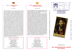
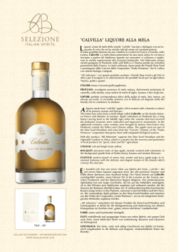
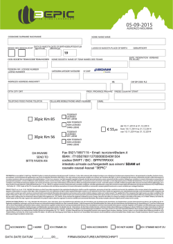
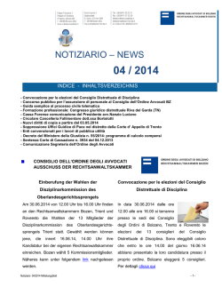
Technology to Create
TECHNICAL
AREA
AVENUE
XXL
METAL
XXL
RIVESTIMENTI VENTILATI
VENTILATED FACADES - HINTERLÜFTETE FASSADE
FACADES VENTILÉES - FACHADA VENTILADA
HILITE resta “Maxi” anche per i rivestimenti ventilati: le caratteristiche morfologiche delle lastre infatti consentono applicazioni in parete che sfruttano
leggerezza e dimensioni, permettendo di “cucire” una pelle a misura su ogni possibile edificio.
Si può quindi rivestire un edificio modulare che fa della ripetitività dei moduli la propria peculiarità e caratteristica vincente per l’utilizzo di formati “pieni”
(3000x1500-1200x1000 mm), così come un edificio che richieda elementi multipli, ma differenziati in dimensione e forme, all’interno delle dimensioni
HILITE.
L’applicazione delle lastre in facciata ventilata utilizza la tecnologia, consolidata a livello tecnico e normativo da oltre 30 anni di realizzazioni, dell’assemblaggio
tra elemento di rivestimento ed elementi portanti in alluminio mediante giunti strutturali realizzati in stabilimento, seguendo una rigorosa e meticolosa
procedura.
Lo studio pre-progetto, l’adeguamento degli standard del sistema al singolo edificio, unitamente al controllo sistematico dei materiali e delle superfici
di aggrappaggio del giunto strutturale, consentono infatti di sfruttare appieno le proprietà complementari di HILITE e della struttura in alluminio, ma
soprattutto di eliminare dal cantiere qualsiasi operazione che non sia un semplice ancoraggio meccanico: HILITE per i sistemi di rivestimento, si presenta
quindi preparata ad essere “semplicemente” agganciata e serrata in cantiere alla muratura esistente, con una garanzia dell’assiemaggio in atmosfera
controllata dello stabilimento di produzione.
HILITE stays “maxi” also for ventilated facades: indeed the morphological features of the slabs allow for wall applications that benefit from its lightweight
design and size and allow to “fit” a tailor-made panelling on any building.
It is possible to cover modular buildings, whose distinguishing and successful feature is the repetitivity of its modules to use full-size formats (3000x15001200x1000 mm), as well as buildings that require multiple elements with different sizes and shapes, as part of HILITE’s dimensions.
The application of slabs on ventilated facades employs a well-consolidated technology from a technical and normative point of view in over 30 years of
manufacturing.
This is based on the assembly of the panels and load-bearing aluminium elements by means of structural joints made in our plant according with a rigorous
and meticulous procedure. Indeed the study conducted before developing the project and adjusting the system’s standards to the individual building together with a systematic control of materials and gripping surfaces of the structural joint - allows to fully exploit HILITE’s complementary properties and
its aluminium structure and, in particular, to eliminate any operation other than simple mechanical anchoring at the building site: HILITE for panelling
systems is therefore ready to be “simply” anchored and fastened to existing masonry on site, with the assurance of an assembly conducted in the controlled
environment of the manufacturing plant.
HILITE bleibt auch für hinterlüftete Fassadenverkleidungen “maxi“: die morphologischen Eigenschaften der Platten erlauben Anwendungen an Wänden,
die sich die Leichtigkeit und die Größen zu Nutze machen, und es somit ermöglichen, jedes mögliche Gebäude mit einer auf Maß angefertigten „Haut“ zu
versehen.
Man kann somit ein Modulargebäude verkleiden, das die Eintönigkeit der Module zur eigenen Besonderheit und Gewinneigenschaft macht, dank der
Verwendung der “vollen“ Formate (3000x1500-1200x1000 mm), genau wie ein Gebäude, das zahlreiche Elemente fordert, die jedoch, innerhalb der
Formate HILITE, in Größe und Form variieren.
Die Anwendung der Platten an hinterlüfteten Fassaden basiert auf der, seit über 30 Jahren auf technischem und normativem Niveau erprobten Technologie
des Zusammensetzens des Verkleidungselements und der Tragelemente aus Aluminium, mittels struktureller Verbindungen, die im Werk, einer strengen und
minuziösen Vorgehensweise folgend, hergestellt werden. Die Vorplanung, die Angleichung der Systemstandards an das einzelne Gebäude, zusammen mit
der systematischen Kontrolle der Materialien und der Oberflächen, an die die strukturelle Verbindung angebracht wird, ermöglichen es, die komplementären
Eigenschaften von HILITE und von der Aluminiumstruktur vollständig zu nutzen, und vor allem, jegliche Arbeit, die keine einfache mechanische Verankerung
ist, von der Baustelle fernzuhalten: HILITE für Verkleidungssysteme präsentiert sich also so vorbereitet, dass es, auf der Baustelle, “einfach“ aufgehängt und
mit dem existierenden Mauerwerk verbunden werden kann, mit einer Montage - Garantie im kontrollierten Ambiente des Produktionswerks.
HILITE reste “maxi” même pour les façades ventilées : les caractéristiques morphologiques des dalles permettent des applications murales qui exploitent
la légèreté et les dimensions, permettant de « coudre », sur tout éventuel bâtiment, une peau sur mesure.
Un bâtiment modulaire peut donc être revêtu et faire de la répétitivité des modules sa particularité et son atout pour l’utilisation de formats pleins
(3000x1500-1200x1000 mm), tout comme un bâtiment exigeant des éléments multiples, mais différenciés quant aux formes et aux dimensions, dans
les limites des formats de HILITE.
L’application des dalles pour réaliser une façade ventilée exploite la technologie, aux normes et consolidée du point de vue technique par plus de 30 ans
de réalisations, qui consiste à assembler l’élément de revêtement et les éléments portants en aluminium au moyen de joints structuraux fabriqués en usine
suivant une méthode rigoureuse et méticuleuse. L’avant-projet, l’adaptation des standards du système à chaque bâtiment et le contrôle systématique des
matériaux et des surfaces d’accrochage du joint structural permettent d’exploiter pleinement les propriétés complémentaires de HILITE et de la structure en
aluminium, mais surtout d’éliminer du chantier toute opération autre qu’un simple ancrage mécanique : par conséquent, pour les systèmes de revêtement,
HILITE est prête à être tout simplement accrochée, sur le chantier, et fixée sur la maçonnerie existante, l’usine de production garantissant l’assemblage
sous atmosphère contrôlée.
HILITE sigue siendo “maxi” también para las fachadas ventiladas: las características morfológicas de las losas hacen posible la aplicación en paredes que
aprovechan la ligereza y las dimensiones, para poder “coser” una piel a medida en cada edificio posible.
Se puede, por tanto, revestir un edificio modular que hace de la repetitividad de los módulos su rasgo distintivo y la característica ganadora para el uso
de formatos “llenos” (3000x1500-1200x1000 mm), al igual que un edificio que requiera elementos múltiples, pero diferenciados en cuanto a tamaños
y formas, dentro de las dimensiones HILITE.
La aplicación de las losas en la fachada ventilada emplea la tecnología, consolidada a nivel técnico y normativo desde hace más de 30 años de
realizaciones, del ensamblaje entre el elemento de revestimiento y los elementos portantes de aluminio, mediante juntas estructurales realizadas en el
establecimiento, siguiendo un procedimiento riguroso y meticuloso. El estudio preliminar, la adaptación de los estándares del sistema a cada edificio,
junto con el control sistemático de los materiales y de las superficies de sujeción de la junta estructural, permiten aprovechar plenamente las propiedades
complementarias de HILITE y de la estructura de aluminio, pero sobre todo eliminar de la obra cualquier operación que no se trate de una simple sujeción
mecánica: HILITE para los sistemas de revestimiento, se presenta, pues, lista para ser “sencillamente” enganchada y sellada en la obra a los muros
existentes, con la garantía de ensamblaje en la atmósfera controlada del establecimiento de producción.
104
105
AVENUE
XXL
METAL
XXL
RIVESTIMENTI VENTILATI
VENTILATED FACADES - HINTERLÜFTETE FASSADE
FACADES VENTILÉES - FACHADA VENTILADA
Maxi Ventilated è stata sviluppata proprio per consentire la massima flessibilità per il progettista utilizzando due sottofamiglie di sistemi, che hanno in
comune l’assemblaggio struttura/lastra tramite giunto strutturale, ma che si differenziano nella tipologia di struttura che consente di ancorare HILITE alla
parete dell’edificio:
- Maxi Frame, che utilizza un telaio perimetrale autoportante disegnato per essere direttamente appeso a staffe modulari ancorate alla parete dell’edificio;
- Maxi Light, che utilizza invece profili di raccordo verticali sagomanti per essere fissati ad un tradizionale reticolo montanti e traversi pre-fissato alla parete.
Maxi Ventilated has been developed precisely to allow HILITE flexibility for the designer using two system sub-groups with the same assembly procedure of
the structure/slab by means of a structural joint, but a different structure to anchor HILITE to the building’s wall:
- Maxi Frame, which employs a self-supporting perimeter frame designed to be hanged on to modular brackets anchored to the building’s wall;
- Maxi Light, which instead employs vertical shaped connecting profiles that are fixed to a traditional grid of uprights and crossbeams pre-fixed to the wall.
Maxi Ventilated ist genau dafür entwickelt worden, um dem Planer die maximale Flexibilität zu bieten, indem zwei Untergruppen von Systemen verwendet
werden, die das Zusammensetzen von Struktur und Platte mittels struktureller Verbindung gemeinsam haben, sich jedoch in der Typologie der Struktur
unterscheiden, die es ermöglicht, HILITE an die Gebäudewand anzubringen:
- Maxi Frame, das ein selbsttragendes Außengestell verwendet, vorgesehen für direkte Anhängung an Modularklammern, die in der Gebäudewand
verankert sind
- Maxi Light, das, hingegen, senkrechte Verbindungsprofile verwendet, geformt für Fixierung an traditionellen Rahmengitter, die an der Wand vormontiert werden
Maxi Ventilated a été développé justement pour offrir au concepteur la flexibilité maximale en utilisant deux sous-familles de systèmes qui ont en commun
l’assemblage structure/dalle au moyen d’un joint structural, mais qui se différencient dans le type de structure permettant de fixer HILITE sur le mur du
bâtiment :
- Maxi Frame, qui utilise un châssis périmétrique autoporteur conçu pour être directement accroché à des brides modulaires fixées sur le mur du bâtiment
- Maxi Light, qui utilise en revanche des profilés de raccordement verticaux modelés pour être fixés sur un treillis traditionnel, de montants et de travers,
préfixé sur le mur.
Maxi Ventilated se ha desarrollado precisamente para ofrecer la máxima flexibilidad al proyectista utilizando dos subfamilias de sistemas, que tienen en
común el ensamblaje estructura/losa mediante junta estructural, pero que se diferencian en cuanto al tipo de estructura que permite fijar HILITE a la
pared del edificio:
- Maxi Frame, que hace uso de un bastidor perimetral autoportante diseñado para suspenderse directamente sobre soportes modulares fijados
a la pared del edificio;
- Maxi Light, que utiliza, en cambio, perfiles de unión verticales, perfilados para ser fijados a una estructura reticular de largueros y vigas fijada
previamente a la pared.
106
MAXI FRAME
MAXI LIGHT
107
AVENUE
XXL
METAL
XXL
RIVESTIMENTI VENTILATI
VENTILATED FACADES - HINTERLÜFTETE FASSADE
FACADES VENTILÉES - FACHADA VENTILADA
La scelta per definire quale dei due sistemi sia il più appropriato all’edificio da rivestire risulta essere in funzione di vari parametri:
- Dimensione del progetto
- Modularità del disegno di facciata
- Dimensione del modulo
- Ripetitività del modulo
- Altezza dell’edificio
- Forometria di finestre
- Presenza di aggetti e balconi
- Quantità di elementi speciali
- Organizzazione e logistica di cantiere
Quale indicazione generica, Maxi Frame sarà prevalentemente utilizzato per progetti con elevata magnitudine, sistematica ripetitività del modulo e rilevante
altezza dell’edificio; Maxi Light quando saranno presenti una irregolare forometria di finestre e numerosi aggetti e balconi.
Comunque i due sistemi sono in grado di soddisfare le necessità di qualsiasi edificio, mantenendo altresì un altissimo valore di resistenza ai carichi di vento,
in linea con i valori raggiunti dai migliori rivestimenti ventilati tradizionali con lastre ceramiche.
Nei sistemi Maxi Ventilata infatti, le lastre continuano ad avere mera funzione di elemento “portato”, lasciando alle strutture di alluminio il compito di
sopportare i carichi, limitare le flessioni degli elementi e di trasferire quindi detti carichi alla struttura muraria: l’appropriato studio del posizionamento degli
elementi di alluminio e dei giunti strutturali, eseguito per singolo progetto, consente di dissipare carichi eccessivi per la lastra e garantirne quindi l’integrità
e la longevità. L’opportunità di scegliere tra due sistemi suggerisce quindi di analizzare in fase preliminare di progetto dell’edificio l’intreccio dei parametri
sopraindicati, al fine di massimizzare resa tecnica ed economica, individuando il sistema più adatto e/o quello più facilmente mediabile.
Nella progettazione preliminare del rivestimento si dovrà ovviamente considerare che, se il “cucire addosso all’edificio una pelle” genererà dei tagli sartoriali
del tessuto (alias ceramica), tali sfridi andranno a gravare sull’onere della realizzazione.
Identificare una complementarietà tra le dimensioni del modulo HILITE e quelle dell’edificio da rivestire permette di conseguenza di ottimizzare la
realizzazione: in un edificio di nuova costruzione ciò può avvenire coordinando la progettazione, mentre in caso di ristrutturazione di un edificio esistente
l’adeguarsi alle dimensioni e alle caratteristiche architettoniche di quanto già realizzato potrebbe rendere oneroso l’utilizzo del Maxi Frame a vantaggio della
maggior flessibilità Maxi Light.
Maxi Frame e Maxi Light sono sviluppabili all’interno dei limiti dimensionali riportati in tabella. (pag. 51)
Identifying which of the two systems is the most suitable one for the building to be covered depends on various parameters:
- Extent of the project
- Modularity of the facade’s design
- Size of the module
- Repetitivity of the module
- Height of the building
- Size of the windows
- If there are any projecting elements or balconies
- Amount of special elements
- Organisation and logistics of the building site.
As a generic indication, Maxi Frame is mostly used for large projects with a regular repetitivity of the modules and a relevant building height, while Maxi Light
is used with irregular window sizes and numerous projecting elements and balconies.
However, the two systems can meet the needs of any building, whilst also maintaining very high resilience to wind loads, in line with the values attained by
top traditional ventilated panelling systems with ceramic slabs.
Indeed, in Maxi Ventilated systems, the slabs still act only as a “supported” element and let the aluminium structures support the loads, limiting the
elements’ flexure and therefore transferring these loads to the wall structure: a suitable study of the positioning of the aluminium elements and structural
joints - conducted for each project - allows to dissipate excessive loads for the slab and therefore ensure its integrity and longevity.
So the opportunity of choosing between two systems indicates the need to analyse - when the preliminary design of the building is conducted - the links
between the parameters mentioned above, in order to maximise the technical performance and economic return by identifying the best-suited system and/
or the one that is easier to implement.
During the preliminary design of the panelling system, it is clearly necessary to consider that, while fitting a tailor-made structure on the building means the
“fabric” (i.e. ceramic) needs to be cut, these “scraps” will have a strong impact on the cost to manufacture the system.
Identifying a complementarity between the size of the HILITE module and that of the building to cover allows to optimise the manufacturing process: in a
new building, this can be done by co-ordinating the design process, while in renovations of existing buildings, adjusting the size and architectural features of
what has already been created could mean the Maxi Frame would be expensive to use, to the benefit of the greater flexibility of Maxi Light.
Maxi Frame and Maxi Light can be installed inside the limits in terms of size reported in the table.
Die Entscheidung, letztendlich, welches der beiden Systeme für das Gebäude, das verkleidet werden soll geeigneter erscheint, hängt von verschiedenen
Parametern ab:
- Größe / Komplexität des Projekts
- Modularität des Fassadenbilds
- Größe des Moduls
- Wiederholung des Moduls
- Höhe des Gebäudes
- Anordnung der Fensteröffnungen
- Vorhandene Vorbauten und Balkone
- Anzahl spezieller Elemente
- Organisation und Logistik auf der Baustelle
Als genereller Vorschlag wird Maxi Frame vorwiegend bei Projekten angewendet mit hoher Größe / Komplexität, systematischer Wiederholung des Moduls
und einer bedeutenden Höhe des Gebäudes; Maxi Light, hingegen, bei unregelmäßiger Fensteranordnung und zahlreichen Vorbauten und Balkonen.
Auf alle Fälle sind beide Systeme fähig, den Notwendigkeiten eines jeden Gebäudes zu entsprechen, da sie ebenfalls eine Hohe Widerstandskraft bei
Windstößen aufweisen, im Einklang mit den hinzukommenden Werten bester, traditioneller hinterlüfteter Fassadenverkleidungen mit Keramikplatten.
In den Systemen Maxi Ventilata behalten die Platten die pure Funktion des “getragenen“ Elements und überlassen den Aluminiumstrukturen die Aufgabe,
Belastungen abzuwenden, die Biegung der Elemente in Grenzen zu halten und die eben genannten Belastungen an die Mauerstruktur weiterzuleiten: die
angemessene Untersuchung der Positionierung der Aluminiumelemente und der strukturellen Vebindungen, die für jedes Projekt separat ausgeführt wird,
ermöglicht es, übermäßige Belastungen für die Platten zu vermeiden, und somit Intaktheit und Langlebigkeit zu garantieren.
Die Möglichkeit zwischen zwei Systemen zu wählen legt es nahe, in der Vorplanungsphase des Gebäudes die Reihe der oben genannten Parameter zu
analysieren, mit dem Ziel, die technische und wirtschaftliche Leistung zu maximieren, indem das geeigneteste System und/oder das am einfachsten zu
handhaben ist, bestimmt wird.
In der Vorplanung der Verkleidung muss somit ganz offensichtlich betrachtet werden, dass, falls “das Annähen der Haut ans Gebäude“ zu Bekleidungsschnitten des Stoffes (alias Keramik) führt, Abfallsschnitte die Ausgaben für die Realisierung in die Höhe treiben.
Beobachtet man eine Komplementarität zwischen der Größe des Moduls HILITE und der Größe des zu verkleidenden Gebäudes, so erlaubt dies in der
Folge die Realisierung zu optimieren: bei einem Neubaugebäude kann dies der Fall sein, wenn man die Planung koordiniert, bei der Restauration eines
bestehenden Gebäudes hingegen, könnte die Anpassung an die Größen und architektonischen Eigenschaften des bereits Bestehenden den Gebrauch von
Maxi Frame erschweren, zum Vorteil der höheren Flexibilität von Maxi Light.
Maxi Frame und Maxi Light sind innerhalb der Größengrenzen, die in der Tabelle wiedergegeben sind, entwickelt.
108
109
AVENUE
XXL
METAL
XXL
RIVESTIMENTI VENTILATI
VENTILATED FACADES - HINTERLÜFTETE FASSADE
FACADES VENTILÉES - FACHADA VENTILADA
Le système le plus approprié au bâtiment à revêtir sera choisi en fonction de plusieurs paramètres :
- Ampleur du projet
- Modularité du plan de façade
- Dimension du module
- Répétitivité du module
- Hauteur du bâtiment
- Plan des ouvertures fenêtres
- Présence d’encorbellements et de
balcons
- Quantité d’éléments spéciaux
- Organisation et logistique de chantier
À titre indicatif, Maxi Frame sera essentiellement utilisé pour des projets de grande ampleur, avec une répétitivité systématique du module et un bâtiment
très haut et Maxi Light lorsque le plan des ouvertures fenêtres sera irrégulier et qu’il y aura de nombreux encorbellements et balcons.
Les deux systèmes sont toujours capables de répondre aux besoins des bâtiments quels qu’ils soient, tout en gardant une très grande résistance aux
charges de vent, en ligne avec les valeurs atteintes par les meilleurs revêtements ventilés traditionnels en dalles céramiques.
Dans les systèmes Maxi Ventilata, les dalles maintiennent leur simple fonction d’élément porté, laissant aux structures en aluminium la tâche de supporter
les charges, de limiter les flexions des éléments et de transférer lesdites charges sur la structure de maçonnerie : effectuée pour chaque projet, l’étude
appropriée du positionnement des éléments en aluminium et des joints structuraux permet de dissiper les charges excessives pour la dalle et de garantir
ainsi son intégrité et sa longévité.
Ayant la possibilité de choisir entre deux systèmes, il est conseillé d’analyser l’ensemble des paramètres susmentionnés pendant la phase préliminaire de
projet du bâtiment afin de maximiser le rendement technique et économique et d’opter pour le système adéquat ou le plus facile à adapter.
Dans la conception préliminaire du revêtement, il faudra évidemment considérer que si le fait de coudre une peau sur le bâtiment signifie couper le tissu
(= céramique) sur mesure, les déchets alourdiront le coût de réalisation.
Trouver une complémentarité entre Ies dimensions du module HILITE et celles du bâtiment à revêtir permet par conséquent d’optimiser la réalisation :
dans un bâtiment nouvellement construit, cela peut se produire en coordonnant la conception, tandis que dans le cas de rénovation d’un bâtiment existant,
l’adaptation aux dimensions et aux caractéristiques architecturales de ce qui est déjà réalisé rendrait l’utilisation du Maxi Frame onéreuse, à l’avantage de
Maxi Light qui est plus flexible.
Maxi Frame et Maxi Light sont développables dans les limites dimensionnelles indiquées dans le tableau.
El criterio para determinar cuál de los dos sistemas es el más adecuado para el edificio en cuestión, depende de varios parámetros:
- Extensión del proyecto
- Modularidad del diseño de la fachada
- Dimensiones del módulo
- Repetitividad del módulo
- Altura del edificio
- Tamaño de las ventanas
- Presencia de voladizos y balcones
- Cantidad de elementos especiales
- Organización y logística de la obra
Como indicación general, Maxi Frame se utilizará primordialmente en proyectos de gran magnitud, con repetitividad sistemática del módulo y altura
relevante del edificio; Maxi Light cuando se presente irregularidad en el tamaño de las ventanas y haya numerosos voladizos y balcones.
Sin embargo, los dos sistemas tienen la capacidad de satisfacer las necesidades de cualquier edificio, manteniendo en todo caso un altísimo valor de
resistencia a las cargas de viento, en línea con los valores que ofrecen las mejores fachadas ventiladas tradicionales con losas cerámicas.
En los sistemas Maxi Ventilata, de hecho, las losas siguen teniendo una función de elemento puramente “suspendido”, dejando a las estructuras de
aluminio la tarea de soportar las cargas, limitar las flexiones de los elementos y transferir dichas cargas a la estructura de los muros: el estudio apropiado
de la colocación de los elementos de aluminio y de las juntas estructurales, realizado para cada proyecto, permite eliminar las cargas excesivas para la
losa y garantizar así la integridad y la durabilidad de las mismas.
La oportunidad de elegir entre dos sistemas sugiere por tanto analizar en la fase preliminar de proyecto del edificio la serie de parámetros arriba
mencionados, para maximizar el rendimiento técnico y económico, y determinar así cuál es el sistema más adecuado o el más fácil de implementar.
En el diseño preliminar del revestimiento, se debe considerar naturalmente que si la “costura de una piel sobre el edificio” genera cortes a medida del tejido
(alias cerámica), dichos recortes pesarán sobre los costes de la realización.
Identificar un carácter complementario entre las dimensiones del módulo HILITE y las del edificio que se ha de revestir, permite por consiguiente optimizar
la realización: en un edificio de nueva construcción esto puede hacerse coordinando el diseño, mientras que en caso de reforma de un edificio ya existente,
la adaptación a las dimensiones y a las características arquitectónicas de lo que ya se ha realizado, podría aumentar los costes del uso del Maxi Frame y
hacer resultar más conveniente la mayor flexibilidad del Maxi Light.
Maxi Frame y Maxi Light se han desarrollado dentro de los límites de dimensiones expuestos en la tabla.
110
111
AVENUE
XXL
METAL
XXL
RIVESTIMENTI VENTILATI
VENTILATED FACADES - HINTERLÜFTETE FASSADE
FACADES VENTILÉES - FACHADA VENTILADA
Maxi Frame e Maxi Light sono ovviamente compatibili: ciò consente, in funzione dell’edificio o del progetto, di utilizzare eventualmente entrambi i sistemi,
differenziandone l’utilizzo in zone omogenee: ovviamente Maxi Frame per le zone a modulo costante, Maxi Light per i sottomultipli ed elementi speciali.
Il dimensionamento delle fughe tra le singole lastre HILITE dovrà essere accuratamente determinato per consentire la dilatazione termica degli elementi ed
evitare che gli stessi sottopongano la lastra ceramica a carichi non appropriati. La dilatazione termica è un fenomeno naturale, tipico di ciascun materiale
ed è in funzione della lunghezza dell’elemento in considerazione: più un elemento è lungo, maggiore sarà a livello assoluto il suo allungamento.
Un valido parametro progettuale da utilizzare per costruzioni in alluminio e ceramica nelle zone temperate del globo terrestre varia da 1,5 a 2 mm per
metro lineare.
Aggiungendo a tale parametro la tolleranza di sistema necessaria per i corretti assemblaggio e montaggio dei componenti di un sistema a secco con lastre
di 3000 mm, la fuga necessita di una dimensione minima teorica di 6 mm.
Entrambi i sistemi, seppur con valenze economiche diverse posso essere dotati di:
- Rete di sicurezza capace di limitare la caduta di frammenti di lastra frantumata per impatto anomalo;
- Ritegno meccanico continuo, bilaterale o puntuale;
- Chiusura delle fughe tra le lastre onde creare una prima barriera all’acqua, capace di limitare la quantità della stessa all’interno dell’intercapedine ventilata.
Maxi Frame and Maxi Light are of course compatible: in relation to the building or project, this allows to use both systems – if necessary – in different areas
with similar features: clearly Maxi Frame is employed in areas with constant modules and Maxi Light for sub-modules and special elements.
The size of the joints between each HILITE slab must be accurately determined to allow for the thermal expansion of the elements and prevent them
by subjecting the ceramic slab to inadequate loads. Thermal expansion is a natural phenomenon typical of any material and depends on the length of
the element in question: the longer the element, the greater its extension in absolute terms. A good design parameter to use for aluminium and ceramic
buildings in temperate zones around the world varies between 1.5 to 2 mm per linear metre.
By adding the system tolerance required to correctly assemble and install the components of a dry-mounted system with 3000 mm slabs, joints must
theoretically be at least 6 mm wide.
Although they have different costs, both systems can be fitted with:
- A safety net capable of limiting parts of broken slabs from falling due to anomalous impacts;
- A bilateral or punctual continuous mechanical retaining system;
- Closure of the joints between the slabs to create a first barrier against water capable of limiting the amount of water itself inside the ventilated cavity.
Maxi Frame und Maxi Light sind natürlich kompatibel: abhängig vom Gebäude oder vom Projekt, erlaubt dies eventuell beide Systeme zu verwenden,
indem der Gebrauch in homogene Zonen differenziert wird: Maxi Frame, selbstverständlich, für Zonen mit konstantem Modul, Maxi Light für Teilflächen sowie
spezielle Elemente.
Die Größen der Fugen zwischen den einzelnen Platten HILITE müssen akkurat bestimmt werden um die thermische Ausdehnung der Elemente zu
ermöglichen und zu verhindern, dass diese die Keramikplatte ungeeigneten Belastungen aussetzen. Die thermische Ausdehnung ist ein natürliches
Phänomen, typisch für jedes Material und abhängig von der Länge des betrachteten Elements: je länger ein Element ist, desto größer wird, absolut gesehen,
seine Ausdehnung.
Ein gültiger Projektparameter, der für Aluminium- und Keramikkonstruktionen in gemäßigten Klimazonen der Erde verwendet wird, variiert zwischen 1,5 und
2 mm pro laufenden Meter.
Fügt man zu solch einem Parameter die Systemtoleranz hinzu, die notwendig ist für korrektes Zusammensetzen und Montieren der Komponenten eines
Trockensystems mit Platten von 3000 mm, benötigt die Fuge eine theoretische Mindestgröße von 6 mm.
Beide Systeme können, trotz unterschiedlicher wirtschaftlicher Wertigkeiten, ausgestattet werden mit:
- Sicherheitsnetz, um das Herunterfallen von Plattenfragmenten, die aufgrund eines, von der Norm abweichenden Aufpralls abgebrochen sind,
einzuschränken;
- Eine stetige mechanische Rückhaltung, bilateral oder punktuell;
- Verschluss der Fugen zwischen den Platten, von wo aus eine erste Wassersperre entsteht, die dazu dient, die Wassermenge im Inneren des hinterlüfteten
Hohlraums begrenzt zu halten.
Naturellement, Maxi Frame et Maxi Light sont compatibles, ce qui permet, en fonction du bâtiment ou du projet, d’utiliser éventuellement les deux systèmes
en différenciant leur emploi dans des zones homogènes : Maxi Frame pour les zones à module constant et Maxi Light pour les sous-multiples et les
éléments spéciaux.
La largeur du joint entre les dalles HILITE devra être très minutieusement défini pour permettre la dilatation thermique des éléments et éviter qu’ils ne
soumettent la dalle céramique à des charges inappropriées. La dilatation thermique est un phénomène naturel, typique de chaque matériau et il dépend
de la longueur de l’élément considéré : plus un élément est long, plus il s’allongera, au niveau absolu. Un paramètre conceptuel valable, à utiliser pour les
constructions en aluminium et céramique dans les zones tempérées du globe terrestre, varie de 1,5 à 2 mm par mètre linéaire.
En ajoutant à ce paramètre la tolérance de système nécessaire pour assembler et monter correctement les composants d’un système à sec avec des dalles
de 3000 mm, le joint devra avoir une largeur théorique minimale de 6 mm.
Même avec des valeurs économiques différentes, les deux systèmes peuvent être dotés de :
- Grillage de sécurité capable de limiter la chute de fragments de dalle brisée par un impact anormal
- Retenue mécanique continue, bilatérale ou ponctuelle
- Colmatage des joints entre les dalles pour créer une première barrière contre l’eau capable d’en limiter la quantité pénétrant à l’intérieur de la lame
d’air ventilée.
Maxi Frame e Maxi Light son naturalmente compatibles, lo que, según el edificio o el proyecto, permite utilizar ambos sistemas si es necesario, diferenciando
el uso en zonas homogéneas: obviamente Maxi Frame en las zonas con módulo constante, y Maxi Light en los submúltiplos y elementos especiales.
El cálculo de las dimensiones de las juntas entre las losas HILITE debe determinarse con precisión para permitir la dilatación térmica de los elementos y
evitar que estos sometan la losa cerámica a cargas no apropiadas. La dilatación térmica es un fenómeno natural, propio de cada material y depende de
la longitud del elemento en cuestión: entre más largo sea el elemento, mayor será su alargamiento absoluto.
Un parámetro válido que puede utilizarse para construcciones en aluminio y cerámica en las zonas templadas del globo terráqueo, varía de 1,5 a 2 mm
por metro lineal.
Si se añade a este parámetro la tolerancia de sistema necesaria para el ensamblaje y montaje correctos de los componentes de un sistema en seco con
losas de 3000 mm, la junta requiere una dimensión mínima teórica de 6 mm.
Ambos sistemas, si bien presenten valores económicos diferentes, pueden contar con:
- red de seguridad capaz de limitar la caída de fragmentos de losa rota por impactos anómalos;
- fijación mecánica continua, en dos lados o puntual;
- Cierre de las juntas entre las losas para crear una primera barrera contra el agua, capaz de limitar la cantidad de la misma en el interior de la cámara
de aire ventilada.
112
113
AVENUE
XXL
METAL
XXL
RIVESTIMENTI VENTILATI
VENTILATED FACADES - HINTERLÜFTETE FASSADE
FACADES VENTILÉES - FACHADA VENTILADA
Maxi Frame
Maxi Frame è un sistema costituito dalla seguente generica stratigrafia di rivestimento:
- Parete in c.a. o muratura dell’edificio;
- Strato coibente con strato idrorepellente;
- Staffe di ancoraggio regolabili fissate alla parete mediante tasselli o ferri tipo halfen;
- Uncini di aggancio e regolazione verticale;
- Telaio perimetrale autoportante di trasferimento carichi;
- Giunto strutturale;
- Rete di sicurezza;
- Lastra HILITE;
- Eventuale guarnizione perimetrale di barriera;
- Eventuale ritegno meccanico.
Definito il progetto esecutivo della facciata, il sistema Maxi Light, che richiede rispetto a Maxi Frame la posa di un reticolo di facciata, consente di iniziare le
operazioni effettive di montaggio in cantiere contemporaneamente alla preparazione dei manufatti in stabilimento:
- in cantiere si inizia la preparazione logistica e si verificano le tolleranze dimensionali dell’edificio prima di iniziare la tassellatura delle staffe o la correttezza
dei ferri tipo halfen, per procedere con la posa in opera del reticolo montanti-traversi;
- in stabilimento gli elementi in alluminio vengono tagliati a misura e forati e quindi assemblati con le lastre HILITE mediante giunti strutturali in silicone
per creare i pannelli Maxi Light fissabili meccanicamente in cantiere al reticolo di facciata.
Le cellule Maxi Frame vengono quindi poste a riposo per garantire la polimerizzazione del giunto strutturale e per verificare sistematicamente la qualità del
giunto stesso; in seguito le cellule vengono imballate in appositi contenitori e preparate per il trasporto in cantiere.
Ogni singola cellula sarà quindi progettata ed assemblata per essere semplicemente interconnessa a quella adiacente e costituire la “sequenza” che
realizzerà il rivestimento ventilato della parete dell’edificio con una installazione stabilita in sede progettuale, al fine di minimizzare la movimentazione al
piano e di assemblaggio.
La dimensione delle cellule e la ricerca di minimizzare le interferenze logistiche in cantiere suggeriscono di non utilizzare i tradizionali ponteggi per la posa
in opera di Maxi Frame.
La logistica di cantiere dovrà prevedere lo stoccaggio per i contenitori delle cellule, con adeguato spazio circostante per consentire le manovre di
spostamento e di estrazione delle stesse, in funzione dei macchinari che verranno utilizzati per l’accesso alla parete da rivestire, la movimentazione, e la
posa delle cellule; come esemplificazione si indicano le seguenti famiglie:
Accesso del personale in quota:
• Ponteggi mobili
• Pantografo
• Camion con braccio e cesto
Movimentazione e posa:
• Gru
• Fork lift
• Gru mobile al piano
• Monorail
Aggancio delle cellule:
• Ventose
• Cavetti e golfari
Una tipica sequenza di installazione può essere schematizzata come segue:
- Predisposizione sulla muratura da rivestire degli ancoraggi meccanici (staffe e tasselli o ferri tipo halfen)
- Piombatura e serraggio delle staffe in posizione spaziale
- Posa dell’eventuale strato di coibentazione
- Assiemaggio degli uncini nelle cellule
- Tiro in alto delle cellule
- Ancoraggio meccanico delle cellule alle staffe tramite gli uncini
- Regolazione fine della singola cellula nelle due direzioni spaziali prevalenti
- Ripetizione delle tre fasi precedenti per la cellula successiva
- Chiusura con griglie delle fessure di ventilazione
- Realizzazione di terminali ed imbotti finestre
114
Maxi Frame
Maxi Frame is a system consisting of the generic system of layers below:
- Reinforced-concrete wall or brickwork of the building;
- Insulation layer with water-repellent layer;
- Adjustable anchoring brackets fixed to the wall using dowels or Halfen connectors;
- Anchoring and vertical adjustment hooks;
- Self-supporting perimeter frame with load transfer;
- Structural joint;
- Safety net;
- HILITE slab;
- Barrier perimeter junction if required;
- Mechanical retaining device if required.
When the executive project of the facade has been defined, preparation work in terms of logistics is started in the building site, the dimensional tolerances
of the building are checked before plugging the brackets or checking the Halfen connectors. In the meantime, in the plant the aluminium elements of the
perimeter frame are cut to measure and bored, fixed to the frames and then to the HILITE slabs using silicone structural joints to create Maxi Frame panels
complete with their accessories.
The Maxi Frame panels are then set aside to rest in order to ensure the polimerisation of the structural joint and to systematically check the quality of the
joint itself. Then the panels are packed in special containers and prepared to be delivered to the building site.
Every single panel is therefore designed and assembled to be simply connected to the adjacent one and create the “sequence” that forms the ventilated
panelling system on the building’s wall. The installation is defined at the design stage in order to minimise movements to mount the panels onto the
building’s surface and during assembly.
The size of the panels and the attempt to minimise interference in terms of logistics in the building site indicate that it is best not to resort to traditional
scaffolding to install Maxi Frame systems.
The logistics at the building site involves storing the containers of the panels, with enough space around them to allow to move them and take them out, in
relation to the machines used to access the wall to cover, the handing and the installation of the panels. The items below are reported by way of example:
Equipment to allow personnel to work at elevated heights:
• Movable scaffolding
• Pantograph
• Truck with arm and basket
Handling and installation:
• Crane
• Fork-lift truck
• Mobile crane
• Monorail
Panel anchoring:
• Suction cups
• Cables and eyebolts
A typical installation sequence can be briefly illustrated as follows:
- The mechanical anchoring equipment (brackets and dowels or Halfen connectors) is fitted on the brickwork that needs to be covered
- The brackets are sealed with lead and tightened into place
- The insulation layer is installed, if required
- The hooks are assembled on the panels
- The panels are lifted up
- The panels are mechanically anchored onto the brackets via the hooks
- Fine adjustment of each panel in the two dominant directions
- The three steps above are repeated for the next panel
- The grids of the ventilation slots are closed
- The terminals and windows’ intradoses are made
115
AVENUE
XXL
METAL
XXL
RIVESTIMENTI VENTILATI
VENTILATED FACADES - HINTERLÜFTETE FASSADE
FACADES VENTILÉES - FACHADA VENTILADA
Maxi Frame
Maxi Frame ist ein System, das aus der folgenden allgemeinen Schichtbildung der Verkleidung besteht:
- Stahlbeton- oder Mauerwerkwand des Gebäudes;
- Isolierschicht mit wasserabweisender Schicht;
- Regulierbare Verankerungsklammern, die mittels Dübel oder Halfeneisen an der Wand fixiert sind;
- Koppelungshaken und vertikale Regulierung;
- Selbsttragendes Außengestell für Lastübertragung;
- Strukturelle Verbindung;
- Sicherheitsnetz;
- Platte HILITE;
- Eventuelle Außendichtschutz;
- Eventuelle mechanische Rückhaltung.
Steht einmal das Projekt für die Fassade, so beginnt auf der Baustelle die logistische Vorbereitung sowie die Überprüfung der Größentolleranzen des
Gebäudes, bevor es zur Dübelung der Klammern oder zur Korrektur der Halfeneisen kommt. Im Werk werden die Aluminiumelemente des Außengestells
maßgeschneidert und durchlöchert, zum Gestell zusammengesetzt und dann mit den Platten HILITE zusammenmontiert, mittels struktureller
Silikonverbindungen, um komplett mit Accessoires ausgestattete Verkleidungszellen Maxi Frame zu schaffen.
Die Zellen Maxi Frame werden daraufhin im Ruhezustand versetzt, um die Polymerisation der strukturellen Verbindung zu gewährleisten und systematisch
die Qualität der Verbindung selbst zu überprüfen; daraufhin, werden die Zellen in entsprechende Behälter verpackt und für den Transport zur Baustelle
vorbereitet.
Jede einzelne Zelle wird somit geplant und zusammengesetzt, um auf einfache Weise mit der neben liegenden Zelle verbunden zu werden, und die
“Sequenz“ zu bilden, die die hinterlüftete Fassadenverkleidung der Gebäudewand realisiert, wobei die Installierung im Planungsbüro festgelegt wird, um den
horizontalen Transport sowie den Montageaufwand zu minimieren.
Die Größe der Zellen sowie die Versuche, logistische Interferenzen auf der Baustelle zu minimieren, legen es nahe, für die Verlegung von Maxi Frame vor Ort
nicht die traditionellen Gerüste zu verwenden.
Die Logistik der Baustelle sollte die Lagerung der Behälter der Zellen vorsehen, mit angemessener umliegender Fläche, um die nötigen Rück- und
Auslademanöver zu erlauben, in Abhängigkeit von den Geräten, die für den Zugang zur zu verkleidenden Wand, für den Transport und die Verlegung der
Zellen verwendet werden; als Veranschaulichungen werden die folgenden Gruppen angegeben:
Zutritt des Gesamtpersonals:
- bewegliche Gerüste
- Pantograph
- Lastwagen mit Kranarm und Korb
Transport und Verlegung:
- Kran
- Fork lift
- Beweglicher Kran (horizontal)
- Monorail
Verankerung der Zellen:
- Saugnäpfe
- Stahlkabel und Ösenschrauben
Eine typische Installationsabfolge kann wie folgt schematisiert werden:
- Vorbereitung der mechanischen Verankerungen (Klammern und Dübel oder Halfeneisen) an der zu verkleidenden Mauer
- Versiegelung und Spannen der Klammern in räumlicher Position
- Verlegung einer eventuellen Dämmschicht
- Montage der Haken in den Zellen
- Hochziehen der Zellen
- Mechanische Verankerung der Zellen an den Klammern, mittels Haken
- Feinregulierung der einzelnen Zelle in die zwei dominierenden Raumrichtungen
- Wiederholung der drei vorangehenden Phasen für die nächste Zelle
– Rasterschließung der Ventilationsschlitze
- Setzen der Endplatten und der Fensterleibungen
Maxi Frame
Maxi Frame est un système constitué de la stratigraphie de revêtement suivante :
- Mur en béton armé ou maçonnerie du bâtiment
- Couche isolante avec couche hydrofuge
- Ancrages réglables fixés sur le mur au moyen de goupilles ou de fers type halfen
- Crochets et réglage vertical
- Châssis périmétrique autoporteur de transfert de charges
- Joint structural
- Grillage de sécurité
- Dalle HILITE
- Éventuelle garniture périmétrique de barrière
- Éventuelle retenue mécanique.
Le projet exécutif de la façade étant défini, la préparation logistique commence sur le chantier, où l’on vérifie les tolérances dimensionnelles du bâtiment
avant de commencer le renforcement des brides ou la correction des fers type halfen. Pendant ce temps-là, en usine, les éléments en aluminium du châssis
périmétrique sont coupés sur mesure et perforés, assemblés d’abord dans des châssis puis avec les dalles HILITE, au moyen de joints structuraux en
silicone, pour composer des cellules Maxi Frame complètes.
Les cellules Maxi Frame sont ensuite mises au repos pour garantir la polymérisation du joint structural et pour vérifier systématiquement la qualité de celuici. Après quoi, les cellules sont emballées dans des contenants appropriés et préparées pour être transportées sur le chantier.
Chaque cellule sera donc conçue et assemblée pour être simplement interconnectée avec celle d’à côté et former la séquence qui constituera le revêtement
ventilé du mur du bâtiment selon une installation établie au moment du projet afin de minimiser la manutention sur le chantier.
Vu la dimension des cellules et l’effort pour minimiser les interférences logistiques sur le chantier, il est conseillé de ne pas utiliser d’échafaudages
traditionnels pour la pose de Maxi Frame.
La logistique de chantier devra prévoir le stockage des contenants de cellules avec un espace adéquat tout autour pour permettre les manœuvres de
déplacement et d’extraction de celles-ci, en fonction des machines et des outillages qui seront utilisés pour l’accès aux murs à revêtir, la manutention et la
pose des cellules. Voici quelques exemples :
Accès du personnel en hauteur :
• Échafaudages roulants
• Pantographe
• Camion avec flèche et panier
116
Manutention et pose :
• Grue
• Chariot élévateur
• Grue mobile pour les étages
• Monorail
Accrochage des cellules :
• Ventouses
• Câbles et pitons
Schématisation d’une séquence typique d’installation :
- Préparation des ancrages mécaniques (brides et goupilles ou fers type halfen) sur la maçonnerie à revêtir
- Plombage et serrage des brides en position spatiale
- Pose de l’éventuelle couche isolante
- Assemblage des crochets dans les cellules
- Tirage des cellules vers le haut
- Ancrage mécanique des cellules aux brides au moyen des crochets
- Réglage fin de la cellule dans les deux directions spatiales prédominantes
- Répétition des trois phases précédentes pour la cellule suivante
- Fermeture des fentes d’aération avec des grilles
- Réalisation de dalles terminales et d’intrados de fenêtres
Maxi Frame
Maxi Frame es un sistema constituido por las siguientes capas generales de revestimiento:
- pared de hormigón armado o muros del edificio;
- capa aislante con cubierta hidrófuga;
- soportes de fijación regulables fijados a la pared mediante tacos o anclajes tipo Halfen;
- ganchos de fijación y regulación vertical;
- bastidor perimetral autoportante de transferencia de cargas;
- junta estructural;
- red de seguridad;
- losa HILITE;
- posible empaquetadura perimetral de barrera;
- posible fijación mecánica.
Una vez definido el proyecto arquitectónico de la fachada, mientras en la obra se comienza la preparación logística y se constatan las tolerancias
dimensionales del edificio antes en dar inicio a la fijación de los soportes, o que los anclajes Halfen sean adecuados, en el establecimiento los elementos
de aluminio del bastidor perimetral se cortan a medida y se perforan, se ensamblan en bastidores y se ensamblan sucesivamente con las losas HILITE
mediante juntas estructurales de silicona para componer células Maxi Frame de revestimiento con todos sus accesorios.
Las células Maxi Frame se dejan reposar entonces para garantizar la polimerización de la junta estructural y para comprobar sistemáticamente la calidad
de la junta misma; sucesivamente las células se embalan en contenedores adecuados y se preparan para el transporte a la obra.
Cada una de las células se diseña y se ensambla específicamente para poder interconectarse con la célula adyacente y constituir de esta forma la
“secuencia” que dará vida al revestimiento ventilado de la pared del edificio con una instalación establecida en la fase de diseño, para minimizar el
desplazamiento a la planta y de ensamblaje.
La dimensión de las células y los esfuerzos realizados para minimizar las interferencias logísticas en la obra hacen que no se requiera el uso de andamios
tradicionales para la colocación en obra de Maxi Frame.
La logística de la obra debe contemplar el almacenamiento para los contenedores de las células, con un espacio circunstante adecuado para permitir las
maniobras de desplazamiento y extracción de las mismas, en función de las maquinarias que se utilicen para el acceso a la pared que se ha de revestir,
el desplazamiento y la colocación de las células. A título de ejemplo, se indican los siguientes aspectos:
Acceso del personal al nivel en cuestión:
• andamios móviles
• pantógrafo
• camión con brazo y cesta
Desplazamiento y colocación:
• grúa
• montacargas
• grúa móvil en la planta
• monorraíl
Enganche de las células:
• ventosas
• cables y anillas
Una secuencia típica de instalación puede esquematizarse de la siguiente manera:
- Preparación de la fijación mecánica (soportes y tacos o anclajes tipo Halfen) en los muros que se han de revestir
- Emplomadura y apriete de los soportes en posición espacial
- Colocación de la capa de material aislante, si procede
- Ensamblaje de los ganchos en las células
- Tracción hacia arriba de las células
- Fijación mecánica de las células a los soportes mediante los ganchos
- Regulación precisa de cada célula en las dos direcciones espaciales predominantes
- Repetición de las tres fases anteriores para la célula sucesiva
- Cierre con rejillas de las aberturas de ventilación
- Realización de terminales e intradoses de ventanas
117
AVENUE
XXL
METAL
XXL
RIVESTIMENTI VENTILATI
VENTILATED FACADES - HINTERLÜFTETE FASSADE
FACADES VENTILÉES - FACHADA VENTILADA
Maxi Light
Maxi Light è un sistema costituito dalla seguente generica stratigrafia di rivestimento:
- Parete in c.a. o muratura dell’edificio;
- Strato coibente con strato idrorepellente;
- Staffe di ancoraggio regolabili fissate alla parete mediante tasselli o ferri tipo halfen;
- Montanti verticali;
- Traversi orizzontali;
- Profili verticali di trasferimento carichi con ancoraggio sui traversi;
- Giunto strutturale;
- Rete di sicurezza;
- Lastra HILITE;
- Eventuale guarnizione perimetrale di barriera;
- Eventuale ritegno meccanico.
Definito il progetto esecutivo della facciata, il sistema Maxi Light, che richiede rispetto a Maxi Frame la posa di un reticolo di facciata, consente di iniziare le
operazioni effettive di montaggio in cantiere contemporaneamente alla preparazione dei manufatti in stabilimento:
- in cantiere si inizia la preparazione logistica e si verificano le tolleranze dimensionali dell’edificio prima di iniziare la tassellatura delle staffe o la correttezza
dei ferri tipo halfen, per procedere con la posa in opera del reticolo montanti-traversi;
- in stabilimento gli elementi in alluminio vengono tagliati a misura e forati e quindi assemblati con le lastre HILITE mediante giunti strutturali in silicone
per creare i pannelli Maxi Light fissabili meccanicamente in cantiere al reticolo di facciata.
I pannelli Maxi Light assemblati vengono posti a riposo per garantire la polimerizzazione del giunto strutturale e per verificare sistematicamente la qualità
del giunto stesso; quindi imballati in appositi contenitori e preparati per il trasporto in cantiere.
La dimensione dei pannelli Maxi Light permette, nella maggior parte dei casi, di utilizzare i tradizionali ponteggi, e quindi la logistica di cantiere sarà del tutto
simile a quella di una facciata ventilata tradizionale in ceramica; come esemplificazione si indicano le seguenti famiglie:
Accesso del personale in quota e posa:
• Ponteggi fissi
• Ponteggimobili
Movimentazione:
• Gru di cantiere
• Gru mobile
Una tipica sequenza di installazione può essere schematizzata come segue:
- Predisposizione sulla muratura da rivestire degli ancoraggi meccanici (generalmente staffe e tasselli)
- Tiro in alto dei materiali
- Piombatura e serraggio delle staffe
- Posa dell’eventuale strato di coibentazione
- Posa dei montanti verticali
- Posa dei traversi orizzontali
- Ancoraggio meccanico dei pannelli ai traversi
- Regolazione fine della singola cellula nelle due direzioni prevalenti
- Chiusura con griglie delle fessure di ventilazione
- Realizzazione di terminali ed imbotti finestre
Maxi Light
Maxi Light is a system consisting of the generic system of layers below:
- Reinforced-concrete wall or brickwork of the building;
- Insulation layer with water-repellent layer;
- Adjustable anchoring brackets fixed to the wall using dowels or Halfen connectors;
- Vertical uprights;
- Horizontal crossbeams;
- Vertical profiles to transfer loads with anchoring on the crossbeams;
- Structural joint;
- Safety net;
- HILITE slab;
- Barrier perimeter junction if required;
- Mechanical retaining device if required.
Once the executive project of the facade has been completed, the Maxi Light system – which, compared with the Maxi Frame system, requires the
application of a grid on the facade – can be installed on site, while the panels are being prepared in the plant:
- preparation work in terms of logistics begins in the building site and the dimensional tolerances of the building are checked before plugging the brackets
or checking the Halfen connectors to be able to proceed with the installation of the grid of uprights-crossbeams;
- in the plant, the aluminium elements are cut to measure and bored. They are then assembled together with the HILITE slabs using silicone structural
joints to create Maxi Light panels that can be fixed with mechanical means to the grid on the facade at the building site.
The Maxi Light panels assembled are then set aside to rest in order to ensure the polimerisation of the structural joint and to systematically check the quality
of the joint itself. Then the panels are packed in special containers and prepared to be delivered to the building site.
In most cases, the size of the Maxi Light panels allows to use traditional scaffolding. This means that the logistics of the building site is identical to that one
used for traditional ventilated facades made with ceramic. The items below are reported by way of example:
Equipment to allow personnel to work at elevated heights:
• Fixed scaffolding
• Movable scaffolding
Handling:
• Crane in the building site
• Mobile crane
A typical installation sequence can be briefly illustrated as follows
- The mechanical anchoring equipment (usually brackets and dowels or Halfen connectors) is fitted on the brickwork that needs to be covered
- The materials are lifted up
- The brackets are sealed with lead and tightened
- The insulation layer is installed, if required
- The vertical uprights are installed
- The horizontal crossbeams are installed
- The panels are anchored to the crossbeams with mechanical means
- Fine adjustment of each panel in the two dominant directions
- The grids of the ventilation slots are closed
- The terminals and windows’ intradoses are made
118
119
AVENUE
XXL
METAL
XXL
RIVESTIMENTI VENTILATI
VENTILATED FACADES - HINTERLÜFTETE FASSADE
FACADES VENTILÉES - FACHADA VENTILADA
Maxi Light
Maxi Light ist ein System, das aus der folgenden allgemeinen Schichtbildung der Verkleidung besteht:
- Stahlbeton- oder Mauerwerkwand des Gebäudes;
- Isolierschicht mit wasserabweisender Schicht;
- Regulierbare Verankerungsklammern, die mittels Dübel oder Halfeneisen an der Wand fixiert sind;
- Vertikale Pfosten;
- Horizontale Querbalken;
- Vertikale Profile zur Lastübertragung, mit Verankerung auf den Querbalken;
- Strukturelle Verbindung;
- Sicherheitsnetz;
- Platte HILITE;
- Eventuelle Außendichtschutz;
- Eventuelle mechanische Rückhaltung.
Steht einmal das Projekt für die Fassade, erlaubt es das System Maxi Light, das im Gegensatz zu Maxi Frame die Verlegung eines Fassadengitters erfordert,
die tatsächlichen Montagearbeiten auf der Baustelle zeitgleich mit der Vorbereitung der Arbeiten im Werk zu beginnen:
- Auf der Baustelle beginnt die logistische Vorbereitung sowie die Überprüfung der Größentolleranzen des Gebäudes, bevor es zur Dübelung der Klammern
oder zur Korrektur der Halfeneisen kommt, um fortzufahren mit der Verlegung des Pfosten-Querbalken-Gitters vor Ort;
- Im Werk werden die Aluminiumelemente des Außengestells maßgeschneidert und durchlöchert, und somit mit den Platten HILITE zusammenmontiert,
mittels struktureller Silikonverbindungen, um die Paneele Light zu schaffen, die, vor Ort, mechanisch an das Fassadengitter fixiert werden.
Die zusammengesetzten Paneele Maxi Light werden in Ruhezustand versetzt, um die Polymerisation der strukturellen Verbindung zu gewährleisten und
systematisch die Qualität der Verbindung selbst zu überprüfen; daraufhin, werden sie in entsprechende Behälter verpackt und für den Transport zur Baustelle
vorbereitet.
Die Größe der Paneele Maxi Light erlaubt es in den meisten Fällen traditionelle Gerüste zu verwenden; somit wird die Baustellenlogisitik ganz ähnlich wie
jene einer traditionellen hinterlüfteten Fassade in Keramik; als Veranschaulichung werden folgende Gruppen angegeben:
Zutritt des gesamten Verlegungspersonals:
- Feststehende Gerüste
- Bewegliche Gerüste
Transport:
- Baustellenkran
- Beweglicher Kran
Eine typische Installationsabfolge kann wie folgt schematisiert werden:
- Vorbereitung der mechanischen Verankerungen (im Regelfall Klammern und Dübel) an
der zu verkleidenden Mauer
- Hochziehen der Materialien
– Versiegelung und Spannen der Klammern
- Verlegung einer eventuellen Dämmschicht
- Verlegung vertikaler Pfosten
- Verlegung horizontaler Querbalken
- Mechanische Verankerung der Paneele an den Querbalken
- Feinregulierung der einzelnen Zelle in die zwei dominanten Richtungen
- Rasterschließung der Ventilationsschlitze
- Setzen der Endplatten und der Fensterleibungen
Maxi Light
Maxi Frame est un système constitué de la stratigraphie de revêtement suivante :
- Mur en béton armé ou maçonnerie du bâtiment
- Couche isolante avec couche hydrofuge
- Ancrages réglables fixés sur le mur au moyen de goupilles ou de fers type halfen
- Montants verticaux
- Travers horizontaux
- Profilés verticaux de transfert de charges avec ancrage sur les travers
- Joint structural
- Grillage de sécurité
- Dalle HILITE
- Éventuelle garniture périmétrique de barrière
- Éventuelle retenue mécanique.
Le projet exécutif de la façade étant défini, le système Maxi Light, qui demande contrairement à Maxi Frame la pose d’un treillis de façade, permet de
commencer les opérations effectives de montage sur le chantier en même temps que la préparation des ouvrages en usine :
- la préparation logistique commence sur le chantier et on vérifie les tolérances dimensionnelles du bâtiment avant de commencer le renforcement des
brides ou la correction des fers type halfen, pour poursuivre avec la pose du treillis montants/travers
- En usine, les éléments en aluminium sont coupés sur mesure et perforés, puis assemblés avec les dalles HILITE au moyen de joints structuraux en
silicone, pour créer les panneaux Light fixables mécaniquement sur le treillis de façade, sur le chantier.
Les panneaux Maxi Light sont ensuite mis au repos pour garantir la polymérisation du joint structural et pour vérifier systématiquement la qualité de celui-ci.
Après quoi, ils sont emballés dans des contenants adéquats et préparés pour être transportés sur le chantier.
La dimension des panneaux Maxi Light permet, dans la plupart des cas, d’utiliser les échafaudages traditionnels, par conséquent la logistique de chantier
sera la même que celle d’une façade ventilée traditionnelle en céramique. Voici quelques exemples :
Accès du personnel en hauteur et pose :
• Échafaudages fixes
• Échafaudages roulants
Manutention :
• Grue de chantier
• Grue mobile
Schématisation d’une séquence typique d’installation :
- Préparation des ancrages mécaniques (brides et goupilles) sur la maçonnerie à revêtir
- Tirage des matériaux vers le haut
- Plombage et serrage des brides
- Pose de l’éventuelle couche isolante
- Pose des montants verticaux
- Pose des travers horizontaux
120
-
Ancrage mécanique des panneaux sur les travers
Réglage fin de la cellule dans les deux directions prédominantes
Fermeture des fentes d’aération avec des grilles
Réalisation de dalles terminales et d’intrados de fenêtres
Maxi Light
Maxi Light es un sistema constituido por las siguientes capas generales de revestimiento:
- pared de hormigón armado o muros del edificio;
- capa aislante con cubierta hidrófuga;
- soportes de fijación regulables fijados a la pared mediante tacos o anclajes tipo Halfen;
- largueros;
- vigas;
- perfiles verticales de transferencia de la carga con fijación sobre las vigas transversales;
- junta estructural;
- red de seguridad;
- losa HILITE;
- posible empaquetadura perimetral de barrera;
- posible fijación mecánica.
Una vez definido el proyecto arquitectónico de la fachada, el sistema Maxi Light, que respecto al Maxi Frame requiere la colocación de una malla de
fachada, permite iniciar las operaciones efectivas de montaje en obra mientras se preparan los elementos de la obra en el establecimiento:
- en la obra se da inicio a la preparación logística y se comprueban las tolerancias dimensionales del edificio antes de comenzar a fijar los soportes, o
que los anclajes Halfen sean adecuados, para proceder con la puesta en obra de la estructura reticular de largueros y vigas;
- en el establecimiento, los elementos de aluminio se cortan a medida y se perforan, y se ensamblan entonces con las losas HILITE mediante juntas
estructurales de silicona para crear los paneles Light que se fijan mecánicamente en la obra a la estructura reticular de la fachada.
Los paneles Maxi Light ensamblados se dejan reposar entonces para garantizar la polimerización de la junta estructural y para comprobar sistemáticamente
la calidad de la junta misma; sucesivamente se embalan en contenedores adecuados y se preparan para el transporte a la obra.
La dimensión de los paneles Maxi Light permite, en la mayor parte de los casos, utilizar los andamios tradicionales, y por tanto la logística de la obra será
la misma de la de una fachada ventilada tradicional en cerámica. A título de ejemplo, se indican los siguientes aspectos:
Acceso del personal al nivel en cuestión y colocación:
• andamios fijos
• andamios móviles
Desplazamiento:
• grúa de obra
• grúa móvil
Una secuencia típica de instalación puede esquematizarse de la siguiente manera
- Preparación de las fijaciones mecánicas (generalmente soportes y tacos) en los muros que se han de revestir
- Tracción hacia arriba del material
- Emplomadura y sellado de los soportes
- Colocación de la capa de material aislante, si procede
- Colocación de los largueros
- Colocación de las vigas
- Fijación mecánica de los paneles a las vigas
- Regulación precisa de cada célula en las dos direcciones predominantes
- Cierre con rejillas de las aberturas de ventilación
- Realización de terminales e intradoses de ventanas
121
AVENUE
XXL
METAL
XXL
MOVIMENTAZIONE E STOCCAGGIO
HANDLING AND STORAGE - UMGANG UND LAGERUNG
MANUTENTION ET STOCKAGE - DESPLAZAMIENTO Y ALMACENAMIENTO
Per una corretta movimentazione dei pallet è necessario l’utilizzo di un carrello elevatore a forche con una lunghezza di almeno 2,5 mt e con posizionamento
delle stesse nella posizione di massima larghezza. In condizioni normali, le forche vanno posizionate al centro del lato lungo del pallet, in quanto le stesse
devono far presa su tutta la profondità del pallet. Per permettere l’estrazione delle lastre con facilità e sicurezza, si consiglia di posizionare i pallet in un’area
adeguata in cui sia possibile muoversi con il carrello elevatore attorno ad ogni lato del pallet.
For the correct handling of the pallets, a fork lift truck must be used, at least 2.5 m long, with the forks positioned in the HILITE width position. Under
normal conditions, the forks are positioned in the middle of the long side of the pallet, as they must grip the whole depth of the pallet. To allow the extraction
of the slabs easily and safely, it is recommended to position the pallets in a suitable area where the lift truck can be moved around all sides of the pallet.
Für einen gerechten Umgang mit den Paletten bedarf es des Gebrauchs eines Gabelstaplers mit einer Länge von mindestens 2,5 m, mit der Positionierung
der Gabeln in maximaler Breite. Bei Normalbedingungen werden die Gabeln in der Mitte der langen Seite der Palette positioniert, so dass sie die gesamte
Tiefe der Palette greifen.
Um das leichte und sichere Herausnehmen der Platten zu ermöglichen, wird empfohlen, die Paletten an einem geeigneten Ort zu positionieren, an dem es
möglich ist, mit dem Stapler an jede Seite der Palette zu gelangen.
Pour manutentionner correctement les palettes, il faut utiliser un chariot élévateur à fourches d’une longueur minimum de 2,5 m et positionner celles-ci
en les écartant à la largeur HILITE. Dans des conditions normales, les fourches doivent être positionnées au milieu de la longueur de la palette car elles
doivent prendre toute la profondeur de celle-ci.
Pour extraire les dalles facilement et en toute sécurité, il est conseillé de positionner les palettes dans une zone adéquate permettant de se déplacer avec
le chariot élévateur tout autour de la palette.
Para desplazar los palés correctamente es necesario utilizar una carretilla elevadora de horquillas con una longitud mínima de 2,5 m colocando estas
últimas en la posición de máxima anchura. En condiciones normales, las horquillas se colocan en el centro del lado largo del palé, dado que deben agarrar
toda la profundidad del palé.
Para permitir la extracción de las placas con facilidad y seguridad, se aconseja colocar los palés en un área adecuada en la que sea posible moverse con
la carretilla elevadora alrededor de todos los lados del palé.
122
123
AVENUE
XXL
METAL
XXL
MOVIMENTAZIONE E STOCCAGGIO
HANDLING AND STORAGE - UMGANG UND LAGERUNG
MANUTENTION ET STOCKAGE - DESPLAZAMIENTO Y ALMACENAMIENTO
Per la movimentazione manuale e la successiva posa in opera delle lastre HILITE, al fine di garantire sicurezza per gli operatori e integrità delle lastre, è
vivamente consigliato l’utilizzo di un telaio dotato di ventose, disponibile su richiesta, indicato in particolare per i formati HILITE di dimensioni significative
(es. 300x150 cm – 150x150 cm) mentre su formati HILITE inferiori (es. 150x75 cm) è sufficiente l’utilizzo di due biventose.
For manual handling and subsequent laying of the HILITE slabs, in order to guarantee the operators’ safety and the integrity of the slabs, it is strongly
recommended to use a frame with suction cups, available upon request, particularly suitable for large dimension HILITE formats (e.g. 300x150 cm 150x150 cm) whereas on smaller HILITE formats (e.g. 150x75 cm) two double suction cups are sufficient.
Für den manuellen Umgang und die anschließende Verlegung der Platten HILITE auf der Baustelle wird dringend empfohlen, um sowohl die Sicherheit der
Arbeiter als auch die Unversehrtheit der Platten zu garantieren, ein Gestell mit Saugnäpfen zu verwenden, das auf Anfrage verfügbar ist und insbesondere
für die großformatigen HILITE - Platten (z.B. 300x150cm – 150x150cm) vorgeschlagen wird, wohingegen es für HILITE - Platten eines kleineren Formats
(z.B. 150x75cm) ausreicht, zwei Doppel-Saugnäpfe zu verwenden.
Pour la manutention manuelle suivie de la pose des dalles HILITE, afin de garantir la sécurité des opérateurs et l’intégrité des matériaux, il est vivement
conseillé d’utiliser un châssis doté de ventouses, disponible sur demande, indiqué notamment pour les formats HILITE de dimensions significatives (par
exemple 300x150 cm – 150x150 cm) tandis que pour les formats HILITE inférieurs (par exemple 150x75 cm) deux biventouses suffiront.
Para el desplazamiento manual y la colocación de las placas HILITE, con el fin de garantizar la seguridad de los operadores y la integridad de las placas,
se aconseja vivamente utilizar un bastidor dotado de ventosas, disponible bajo pedido, especialmente indicado para los formatos HILITE de dimensiones
significativas (p. ej. 300x150 cm – 150x150 cm), mientras que para los formatos HILITE inferiores (p. ej. 150x75 cm) es suficiente utilizar dos ventosas
dobles.
124
Strumentazione necessaria
Gli strumenti per il sollevamento e la movimentazione delle lastre sono da scegliere in funzione della dimensione della lastra e delle attività da svolgere in
cantiere, in particolare:
• Carrello elevatore con forche lunghe 2,5 mt;
• Telaio a ventose per la movimentazione di lastre di grande formato;
• Biventose per la movimentazione di lastre di formato fino a 150x75 cm.
Fasi di lavorazione:
1) Rimuovere il coperchio della gabbia/pallet;
2) Posizionare sulla lastra il telaio di movimentazione a ventose e accertarsi che le stesse aderiscano perfettamente;
3) Per il trasporto orizzontale (sul piano), portare in posizione verticale la lastra e avvalersi delle ruote applicate al telaio di movimentazione.
Instruments required
The instruments for lifting and handling the slabs can be chosen according to the size of the slab and the activities to be performed on the site, in particular:
• Fork lift truck with forks 2.5 m long;
• Frame with suction cups for handling large format slabs;
• Double suction cups for handling slabs with format up to 150x75 cm.
Processing stages:
1) Remove the cover from the cage/pallet;
2) Position the frame with suction cups on the slab and make sure that the cups adhere to it perfectly;
3) For horizontal handling (on the surface), put the slab into a vertical position and use the wheels applied to the handling frame.
Notwendige Werkzeugausrüstung
Die Werkzeuge für das Anheben und den Umgang mit den Platten müssen jeweils in Bezug auf die Größe der Platte und die Arbeit, die auf der Baustelle
ausgeführt werden soll, ausgewählt werden:
• Stapler mit 2,5 m langen Gabeln;
• Gestell mit Saugnäpfen für den Umgang mit großformatigen Platten;
• Doppel-Saugnäpfe für den Umgang mit Platten bis zu einer Größe von 150x75cm.
Bearbeitungsphasen:
1) Den Deckel des Käfigs/der Palette entfernen;
2) Auf der Platte das Gestell mit Saugnäpfen positionieren und sich vergewissern, dass diese perfekt anhaften;
3) Für den horizontalen Transport (in der Ebene), die Platte in die senkrechte Position bringen und alle am Gestell angebrachten Räder nutzen.
Outils nécessaires
Les outils pour le levage et la manutention des dalles doivent être choisis en fonction de la dimension de la dalle et des activités à exercer sur le chantier,
notamment :
• Chariot élévateur avec des fourches de 2, 5 m de longueur
• Châssis à ventouses pour la manutention de dalles grand format
• Biventouses pour la manutention de dalles de format jusqu’à 150x75 cm
Phases d’exécution:
1) Retirez le couvercle de la cage/palette
2) Positionnez sur la dalle le châssis à ventouses et assurez-vous que celles-ci adhèrent parfaitement
3) Pour le transport horizontal, mettez la dalle à la verticale et servez-vous des roues fixées sur le châssis de manutention.
Equipo necesario
El equipo de levantamiento y desplazamiento de las placas debe elegirse en función de las medidas de la placa y de las actividades que deben llevarse
a cabo en la obra, en particular:
• Carretilla elevadora con horquillas de 2,5 m de longitud;
• Bastidor con ventosas para desplazar las placas de formato grande;
• Ventosas dobles para desplazar las placas con formato de hasta 150x75 cm.
Fases de trabajo:
1) Extraer la tapa de la jaula/palé;
2) Colocar sobre la placa el bastidor de desplazamiento con ventosas y asegurarse de que estas se adhieran perfectamente;
3) Para el transporte horizontal (sobre la superficie), poner en posición vertical la placa y utilizar las ruedas aplicadas en el bastidor de desplazamiento.
125
AVENUE
XXL
METAL
XXL
TAGLIO E FORI
CUTTING AND HOLES - SCHNITT UND BOHRUNGEN
COUPE ET TROUS - CORTE Y ORIFICIOS
HILITE permette di essere lavorato con grande facilità tramite l’utilizzo di alcuni semplici strumenti.
Si consiglia di effettuare le lavorazioni su una superficie piana di lavoro, le cui dimensioni siano superiori a quelle della lastra per almeno 5 cm da ogni lato.
Si consiglia di effettuare le lavorazioni di taglio in almeno due operatori, per i fori è sufficiente l’impiego di un solo operatore.
HILITE can be easily processed by using some simple tools.
It is recommended to process the slabs on a flat work surface, at least 5 cm longer than the slab from each side or double suction cup.
It is recommended to perform the cutting operations with at least two operators. One operator is sufficient for making the holes.
HILITE erlaubt es, durch Gebrauch einiger einfacher Werkzeuge, mit großer Leichtigkeit bearbeitet zu werden. Es wird empfohlen, die Bearbeitungen auf einer
ebenen Arbeitsfläche durchzuführen, die an jeder Seite mindestens 5 cm größer ist als die Platte selbst.
Es wird empfohlen, die Schnittbearbeitungen mindestens zu zweit durchzuführen; für die Bohrungen ist ein Arbeiter ausreichend.
HILITE peut être travaillée très facilement en utilisant quelques simples outils. Il est conseillé d’effectuer les travaux sur une surface plane, dont les
dimensions sont supérieures à celles de la dalle d’au moins 5 cm de chaque côté ou biventouse.
Il est conseillé d’effectuer les coupes au moins à deux, mais pour les trous, un seul opérateur suffit.
Las placas HILITE se trabajan con gran facilidad utilizando algunas simples herramientas.
Se aconseja efectuar los trabajos sobre una superficie plana cuyas dimensiones sobrepasen al menos 5 cm las de la placa por cada lado o ventosa doble.
Los trabajos de corte deben ser realizados por lo menos por dos operadores, mientras que para efectuar los orificios es suficiente la presencia de un solo
operador.
Taglio
Strumentazione necessaria
A seconda del tipo di taglio e lavorazione da effettuare sulla lastra, vengono elencate di seguito le attrezzature consigliate:
•
Telaio di movimentazione a ventosa o biventosa
•
Guida da taglio con carrello incisore per tagli lineari da 150/300 cm
•
Pinza troncatrice
•
Foretti a umido
•
Smerigliatrice angolare con disco diamantato
•
Tampone diamantato
Fasi di lavorazione
TAGLI LINEARI fino alla lunghezza massima di 3 metri
1) Segnare alle estremità della lastra la porzione da asportare.
2) Posizionare la guida da taglio con carrello incisore in modo che i riferimenti posti sulla guida coincidano con le linee tracciate sulla lastra.
Bloccare la guida da taglio con carrello incisore per mezzo delle ventose.
3) Incisione:
Per garantire una corretta incisione la pressione e l’avanzamento del carrello d’incisione devono essere costanti per tutta la lunghezza del taglio.
3.1) Incidere per 15 cm una estremità della lastra spingendo il carrello d’incisione verso il bordo della lastra.
3.2) Completare l’incisione fino al bordo opposto della lastra.
4) Troncatura:
4.1) Per mezzo della guida di taglio traslare la lastra fino a che la linea di incisione sporga 5/10 cm dal piano di lavoro.
4.2) Liberare dalle ventose la guida di taglio e spostarla verso il centro della lastra.
4.3) Iniziare la troncatura posizionando la pinza troncatrice in corrispondenza della linea incisa sulla lastra. Esercitare una pressione progressiva fino
a che si noti l’inizio troncatura.
4.4) Portarsi sul bordo opposto e posizionare la pinza troncatrice in corrispondenza della linea incisa sulla lastra. Esercitare una pressione progressiva fino
a che si noti l’inizio troncatura.
126
4.5) Per completare la troncatura, uno o più operatori devono impugnare la porzione da asportare ed esercitare una pressione progressiva verso il basso.
5) La finitura dei bordi del lato tagliato deve esser effettuata utilizzando l’ apposito tampone diamantato.
TAGLI A L
Nel caso di tagli a L (fori per scatole elettriche, angoli interni) si consiglia di arrotondare l’angolo interno praticando preventivamente un foro con appositi
foretti a umido.
TAGLI IN SQUADRO / SCASSI
Tracciare sulla lastra la porzione da asportare. Per limitare le possibilità di rottura è consigliato eseguire un foro di Ø 7mm in corrispondenza del punto di
congiunzione delle due linee tracciate sulla lastra. Con smerigliatrice angolare equipaggiata con disco diamantato seguire le linee tracciate.
FORI RETTANGOLARI
1.1 Tracciare sulla lastra i lati della porzione da asportare
1.2 Eseguire fori di Ø 7mm in corrispondenza dei 4 angoli.
Con smerigliatrice angolare equipaggiata con disco diamantato congiungere i 4 fori.
Cutting
Instruments required
Depending on the type of cut and process to be applied to the slab, the recommended types of tools are listed below:
•
Handling frame with suction cups or double suction cups;
•
Cutting guide with cutting carriage for linear cuts of 150/300 cm;
•
Cutting pliers;
•
Wet core bits;
•
Angle grinder with diamond blade;
•
Diamond buffer.
Processing stages
LINEAR CUTS up to a HILITE length of 3 metres
1) Mark the portion to be removed at the ends of the slab.
2) Position the cutting guide with cutting carriage so that the references on the guide coincide with the lines marked on the slab. Lock the cutting guide
with the cutting carriage in place using the suction cups.
3) Scoring:
To guarantee correct scoring, the pressure and movement of the cutting carriage must be constant along the whole length of the cut.
3.1) Score one end of the slab by 15 cm pushing the cutting carriage towards the edge of the slab.
3.2) Complete the scoring up to the opposite edge of the slab.
4) Cutting off:
4.1) Using the cutting guide move the slab until the scoring line protrudes by 5/10 cm from the work surface.
4.2) Release the cutting guide from the suction cups and move it towards the middle of the slab.
4.3) Start the cutting off process by positioning the cutting pliers in line with the line scored on the slab. Exert progressive pressure until you notice that the
cutting off process has begun.
4.4) Go to the opposite side and position the cutting pliers in line with the line scored on the slab.
Exert progressive pressure until you notice that the cutting off process has begun.
4.5) To complete the cutting off process, one or more operators must grip the portion to be removed and exert progressive pressure downwards.
5) The finishing of the edges on the cut side must be carried out using the special diamond buffer.
L-SHAPED CUTS
For L-shaped cuts (holes for electrical boxes, internal corners) it is recommended to round off the internal angle by making a hole first with suitable wet
core bits.
SQUARE CUTS/CUT-OUT
Mark the portion to be removed on the slab.
To limit the possibility of breaking, it is recommended to make a Ø 7 mm hole in line with the point where the two lines marked on the slab meet. With an
angle grinder equipped with a diamond blade, follow the marked lines.
RECTANGULAR HOLES
1.1 Mark the sides of the portion to be removed on the slab.
1.2 Make Ø 7 mm holes in the 4 corners.
Using an angle grinder equipped with a diamond blade join the 4 holes.
127
AVENUE
XXL
METAL
XXL
TAGLIO E FORI
CUTTING AND HOLES - SCHNITT UND BOHRUNGEN
COUPE ET TROUS - CORTE Y ORIFICIOS
Schnitt
Notwendige Werkzeugausrüstung
Je nach Art des Schnitts und der Bearbeitung, die auf der Platte durchgeführt werden sollen, werden die folgenden empfohlenen Werkzeuge aufgelistet:
•
Gestell mit Saugnäpfen oder Doppel-Saugnäpfe
•
Schnittführer mit Kupferstechwagen für gerade Schnitte von 150/300cm
•
Abbrechzange
•
Nassbohrer
•
Eck-Schleifmaschine mit Diamantscheibe
•
Diamantkissen
Bearbeitungsphasen
Lineare Schnitte bis zu einer Länge von 3 Meter
1) An den Enden der Platte die zu entfernenden Stücke markieren.
2) Den Schnittführer mit Kupferstechwagen so positionieren, dass die darunter liegenden Bezugspunkte und die auf der Platte markierten Linien
übereinanderliegen. Den Schnittführer mit Kupferstechwagen mittels der Saugnäpfe fixieren.
3) Einschnitt:
Um einen korrekten Einschnitt zu garantieren, müssen der Druck und das Vorrücken des Kupferstechwagens für die gesamte Länge des Schnitts
konstant bleiben.
3.1) 15cm tief ein Ende der Platte einschneiden, dabei den Kupferstechwagen in Richtung Rand der Platte schieben.
3.2) Den Einschnitt bis zum gegenüberliegenden Rand der Platte fortsetzen.
4) Das Abbrechen:
4.1) Mittels des Schnittführers die Platte führen, bis die Einschnittslinie 5/10 cm über die Arbeitsfläche hinausragt.
4.2) Den Schnittführer von den Saugnäpfen loslösen und ihn Richtung Mitte der Platte verschieben.
4.3) Das Abbrechen beginnen, indem die Abbrechzange entsprechend der, auf der Platte eingeschnittenen Linie angebracht wird. Anschließend einen Druck
ausüben, bis das Abbrechen beginnt.
4.4) Zum gegenüberliegenden Rand gehen und die Abbrechzange entsprechend der auf der Platte eingeschnittenen Linie anbringen.
Anschließend einen Druck ausüben, bis das Abbrechen beginnt.
4.5) Um das Abbrechen zu Ende zu bringen, müssen ein oder mehrere Arbeiter das zu entfernende Stück ergreifen und anschließend einen Druck nach
unter ausüben.
5) Die Feinbearbeitung der Ränder der geschnittenen Seite erfolgt mittels des entsprechenden Diamantkissens.
SCHNITTE IN L-FORM
Im Falle L-förmiger Schnitte (Aussparrungen für Elektrodosen, Innenwinkel) wird empfohlen, den Innenwinkel abzurunden, indem präventiv eine Bohrung
mit geeignetem Nassbohrer durchgeführt wird.
RECHTECKIGE SCHNITTE
Auf der Platte das zu entfernende Stück markieren. Um möglichen Bruch zu vermeiden, wird empfohlen, eine Bohrung mit 7mm Durchmesser an der Stelle,
an der sich die zwei auf der Platte markierten Linien schneiden, auszuführen. Mit der Eck-Schleifmaschine mit Diamantscheibe den markierten Linien folgen.
RECHTECKIGE BOHRUNGEN
1.1 Auf der Platte die Seiten des zu entfernenden Stücks markieren
1.2. Löcher mit 7mm Durchmesser entsprechend der 4. Winkel durchbohren.
Mit der Eck-Schleifmaschine mit Diamantscheibe die 4 Löcher verbinden.
Coupe
Outils nécessaires
Selon le genre de coupe et le travail à effectuer sur la dalle, voici les outils conseillés :
•
Châssis de manutention à ventouse ou biventouse
•
Guide-coupe avec chariot inciseur pour les coupes linéaires de 150/300 cm
•
Pince (de carreleur)
•
Forets à l’eau
•
Meuleuse d’angle à disque diamant
•
Tampon diamant
Phases d’exécution
COUPES LINÉAIRES jusqu’à une longueur HILITE de 3 mètres
1) Marquez, aux extrémités de la dalle, la portion à enlever.
2) Positionnez le guide-coupe à chariot inciseur de manière à ce que les repères prévus sur le guide coïncident avec les lignes tracées sur la dalle.
Bloquez-le avec les ventouses.
3) Entaille:
Pour garantir une entaille correcte, la pression et l’avance du chariot doivent être constantes sur toute la longueur de la coupe.
3.1) Entaillez sur 15 cm une extrémité de la dalle en poussant le chariot vers le bord de la dalle.
3.2) Complétez l’entaille jusqu’au bord opposé de la dalle.
4) Cassure :
4.1) À l’aide du guide-coupe, déplacez la dalle jusqu’à ce que la ligne d’entaille dépasse de 5/10 cm du plan de travail.
4.2) Libérez le guide-coupe des ventouses et déplacez-le vers le milieu de la dalle.
4.3) Commencez à casser en positionnant la pince au niveau de la rayure sur la dalle. Exercez une pression progressive jusqu’à
ce que la cassure commence.
4.4) Allez sur le bord opposé et positionnez la pince au niveau de la rayure tracée sur la dalle. Exercez une pression progressive jusqu’à ce que
la cassure commence.
4.5) Pour compléter la cassure, un ou plusieurs opérateurs doivent saisir la portion à enlever et exercer une pression progressive vers le bas.
5) La finition des bords du côté coupé doit être effectuée à l’aide du tampon diamant prévu.
Corte
Equipo necesario
Dependiendo del tipo de corte y del trabajo que
se debe efectuar en la placa, a continuación se
listan las herramientas aconsejadas:
•
Bastidor de desplazamiento con ventosa o ventosa doble;
•
Guía de corte con carro de incisión para cortes rectos de 150/300 cm;
•
Pinza tronzadora;
•
Perforadores en húmedo;
•
Esmeriladora angular con disco diamantado;
•
Esponja diamantada.
Fases de trabajo
CORTES RECTOS hasta una longitud máxima de 3 metros
1) Marcar en los extremos de la placa la porción que se debe eliminar.
2) Colocar la guía de corte con carro de incisión de manera que las referencias presentes en la guía coincidan con las líneas trazadas en la placa.
Bloquear la guía de corte con carro de incisión por medio de las ventosas.
128
3) Incisión:
Para garantizar una incisión perfecta, la presión y el avance del carro de incisión deben ser constantes en toda la longitud del corte.
3.1) Incidir unos 15 cm de un extremo de la placa empujando el carro de incisión hacia el borde de la misma.
3.2) Completar la incisión hasta el borde opuesto de la placa.
4) Tronzado:
4.1) Por medio de la guía de corte, trasladar la placa hasta que la línea de incisión sobresalga 5/10 cm de la superficie de trabajo.
4.2) Liberar de las ventosas la guía de corte y desplazarla hacia el centro de la placa.
4.3) Iniciar el tronzado colocando la pinza tronzadora en la posición correspondiente a la línea incidida en la placa.
Ejercer una presión progresiva hasta notar el inicio del tronzado.
4.4) Situarse en el borde opuesto y colocar la pinza tronzadora en la posición correspondiente a la línea incidida en la
placa.
Ejercer una presión progresiva hasta notar el inicio del tronzado.
4.5) Para completar el tronzado, uno o varios operadores deben empuñar la porción que se desea eliminar y ejercer una
presión progresiva hacia abajo.
5) El acabado de los bordes del lado cortado debe efectuarse utilizando la esponja diamantada.
CORTES EN L
En caso de cortes en L (orificios para cajas eléctricas, ángulos internos) se aconseja redondear el ángulo interno realizando previamente un orificio con
perforadores en húmedo adecuados.
CORTES EN ESCUADRA/RECORTES
Trazar en la placa la porción que se desea eliminar. Para limitar las posibilidades de que se rompa, se aconseja efectuar un orificio de Ø 7 mm en el punto
de unión de las dos líneas trazadas en la placa. Con una esmeriladora angular equipada con disco diamantado, seguir las líneas trazadas.
ORIFICIOS RECTANGULARES
1.1 Trazar en la placa los lados de la porción que se desea eliminar.
1.2 Efectuar orificios de Ø 7mm en los 4 ángulos.
Con una esmeriladora angular equipada con disco diamantado, unir los 4 orificios.
129
AVENUE
XXL
METAL
XXL
TAGLIO E FORI
CUTTING AND HOLES - SCHNITT UND BOHRUNGEN
COUPE ET TROUS - CORTE Y ORIFICIOS
Fori
Strumentazione necessaria
A seconda del tipo di foro e lavorazione da effettuare sulla lastra, queste sono le attrezzature che si consiglia di utilizzare:
•
Telaio di movimentazione a ventosa o biventosa
•
Trapano/Avvitatore;
•
Foretti diamantati per foratura a umido (frese a tazza);
•
Smerigliatrice angolare con disco diamantato
Fasi di lavorazione
Fori tondi
1) Posizionare la lastra HILITE su un supporto solido e non scivoloso (es. legno o cemento). Spruzzare acqua nell’area dove verrà praticato il foro;
2) Iniziare ad eseguire il foro ad un angolo di 75°-85° e penetrare nella lastra per circa 1-2 mm di profondità;
3) Mantenere il trapano/avvitatore ad un angolo di 90° ed effettuare movimenti circolari con un angolo di circa 5°-10°. Non esercitare troppa pressione.
Non spingere dritti verso il basso. Assicurarsi che l’acqua sia sufficiente per inumidire la fresa.
4) Pulire dai detriti una volta effettuato il foro.
Holes
Instruments required
Depending on the type of hole and process to be applied to the slab, it is recommended to use the following instruments:
•
Handling frame with suction cups or double suction cups;
•
Drill/Screwdriver;
•
Wet diamond core bits (cup wheel cutters);
•
Angle grinder with diamond blade.
Processing stages
Round holes
1) Position the HILITE slab on a solid, non-slip surface (e.g. wood or concrete). Spray water onto the area where the hole is to be made.
2) Start to make a hole at an angle of 75°-85° and penetrate into the slab with a depth of about 1-2 mm.
3) Keep the drill/screwdriver at a 90° angle and make circular movements with an angle of about 5°-10°.
Do not exert too much pressure. Do not push straight downwards. Make sure there is enough water to wet the cutter.
4) Clean up the scraps once the hole has been made.
Bohrungen
Notwendige Werkzeugausrüstung
Je nach Art der Bohrung und der Bearbeitung, die auf der Platte ausgeführt werden sollen, sind dies die Werkzeuge, die für den Gebrauch empfohlen werden:
•
Gestell mit Saugnäpfen oder Doppel-Saugnäpfe
•
Bohrer / Schrauber
•
Diamantbohrer für Nassbohrungen (Tassenfräser)
•
Eck-Schleifmaschine mit Diamantscheibe
Bearbeitungsphasen
Runde bohrungen
1) Die HILITE - Platte auf einem soliden und rutschfesten Träger (z.B. Holz oder Zement) positionieren.
Die Fläche, auf der die Bohrung vorgenommen wird, mit Wasser bespritzen;
2) Mit der Bohrung mit einem Winkel von 75°-85° beginnen und ca. 1-2 cm tief in die Platte eindringen;
3) Den Bohrer / Schrauber in einem Winkel von 90° halten und mit einem Winkel von ca. 5°-10° kreisförmige Bewegungen ausführen.
Nicht zuviel Druck ausüben. Nicht gerade nach unten drücken. Dafür sorgen, dass genügend Wasser da ist, um die Fräse zu befeuchten.
4) Nachdem die Bohrung gemacht worden ist, Bruchstücke entfernen.
Trous
Outils nécessaires
Selon le genre de trou et le travail à effectuer sur la dalle, voici les outils conseillés :
•
Châssis de manutention à ventouse ou biventouse
•
Perceuse/ Visseuse
•
Forets diamantés pour perçage à l’eau (fraises à godet)
•
Meuleuse d’angle à disque diamant
Phases d’exécution
Trous ronds
1) Positionnez la dalle HILITE sur un support solide et non glissant (bois ou béton). Mouillez à l’eau la zone où le trou sera percé.
2) Commencez à percer le trou sur un angle de 75°-85° et pénétrez dans la dalle à environ 1-2 mm de profondeur.
3) Maintenez la perceuse/visseuse à 90° et effectuez des mouvements circulaires sur un angle d’environ 5°-10°. N’appuyez pas trop.
Ne poussez pas droit vers le bas. Assurez-vous que l’eau est suffisante pour mouiller mouiller la fraise.
4) Une fois que le trou est fait, éliminez les débris.
Orificios
Equipo necesario
En función del tipo de orificio y del trabajo que se debe efectuar en la placa, estas son las herramientas que se aconseja utilizar:
•
Bastidor de desplazamiento con ventosa o ventosa doble;
•
Taladro/Atornillador;
•
Perforadores diamantados para la perforación en húmedo (fresas de taza);
•
Esmeriladora angular con disco diamantado.
Fases de trabajo
Orificios redondos
1) Colocar la placa HILITE en un soporte sólido que no sea resbaladizo (p. ej. madera o cemento).
Rociar con agua el área donde se realizará el orificio;
2) Empezar a efectuar el orificio con un ángulo de 75°-85° y penetrar en la placa hasta 1-2 mm de profundidad;
3) Mantener el taladro/atornillador en un ángulo de 90° y efectuar movimientos circulares con un ángulo de unos 5°-10°.
No ejercer demasiada presión. No empujar recto hacia abajo. Asegurarse de que el agua sea suficiente para humedecer la fresa;
4) Limpiar los detritos una vez efectuado el orificio.
130
131
AVENUE
XXL
METAL
XXL
TAGLIO E FORI
CUTTING AND HOLES - SCHNITT UND BOHRUNGEN
COUPE ET TROUS - CORTE Y ORIFICIOS
Descrizione e caratteristiche tecniche
La posa delle lastre HILITE richiede condizioni di posa simili a quelle richieste per lastre in formato tradizionale. HILITE richiede l’utilizzo della tecnica a
doppia spalmatura, ovvero il collante deve essere applicato sia sul fondo di posa che sul retro della lastra.
Per la posa a pavimento, HILITE richiede le migliori condizioni di sottofondo:
•
planarità;
•
pulizia da polvere, detriti ed eliminazione di grumi di cemento;
•
il fondo di posa deve essere omogeneo e avere già compiuto il ritiro igrometrico di maturazione;
•
riparazione di eventuali fessurazioni;
•
i dislivelli di planarità devono essere colmati con idonei prodotti di rasatura.
Strumentazione necessaria
•
Collante in polvere a base cementizia a letto pieno di classe “C2E secondo le normative EN 12004 e S1 secondo la normativa EN 12002”
•
spatola a denti quadri 3x3 mm e spatola a denti tondi 15 mm;
•
telaio a ventosa per la movimentazione o biventosa
•
battitore in plastica antirimbalzo 170x370 mm;
•
sistema livellante: base + cuneo + pinza.
Fasi di lavorazione
INCOLLAGGIO A PAVIMENTO
1) Assicurarsi che la superficie da rivestire sia consistente, planare, priva di polvere e unti/grassi.
2) Utilizzare i collanti sopra descritti miscelati in base alle specifiche indicate nella scheda tecnica del collante prescelto.
3) Stendere il collante sulla superficie da rivestire con spatola a denti tondi 15 mm per un’area superiore di 5/10 cm rispetto alle dimensioni della lastra.
4) Con la lastra in posizione verticale sul telaio di movimentazione, stendere il collante sul retro della lastra con spatola a denti quadri 3x3 mm.
5) Con l’utilizzo del telaio a ventosa portare la lastra in posizione orizzontale e posarla.
6) Per garantire l’incollaggio uniforme della lastra, si deve utilizzare apposito battitore in plastica anti-rimbalzo 170x370 mm, effettuando una battitura
dal centro verso i bordi per eliminare eventuali sacche d’aria fra il retro della lastra, il collante ed il fondo di posa.
7) Utilizzo di sistema livellante.
SISTEMA LIVELLANTE
Il sistema livellante è volto a garantire con semplicità e rapidità pavimenti perfettamente livellati eliminando i dislivelli (“denti”) tra le lastre. Il sistema
livellante è vivamente consigliato per la posa delle lastre HILITE.
Strumentazione necessaria
•
Base;
•
Cuneo;
•
Pinza regolabile per installazione a pavimento / rivestimento.
Applicazione del sistema livellante
Posizionamento della base:
a) Dopo avere steso il collante inserire la base al di sotto della lastra HILITE in corrispondenza dei 4 lati.
b) In funzione del formato della lastra posizionare uno o più supporti per ogni lato della lastra.
c) Posizionare la lastra.
Inserimento del cuneo:
a) Inserire il cuneo nella feritoia del supporto facendo attenzione a non superare il punto di rottura.
b) Per agevolare l’inserimento del cuneo si consiglia l’uso della pinza a trazione regolabile.
Eliminazione del supporto:
a) A maturazione del collante avvenuta, la parte sporgente del supporto si separa dalla base battendo con il piede nella direzione della linea di fuga.
132
Description and technical features
Laying HILITE slabs requires similar laying conditions to those required for traditional format slabs.
HILITE requires the adhesive to be applied both on the setting bed and on the back of the slab.
HILITE slabs for flooring require the following conditions:
•
A flat surface;
•
Clean and free from dust, scraps and any lumps of cement;
•
The setting bed must be uniform and have already undergone the drying shrinkage process;
•
Repair of any cracks;
•
Any uneven parts on the surface must be filled with suitable levelling compounds.
Instruments required
•
Cement-based powder adhesive for full spread, class “C2E according to EN12004 and S1 according to EN12002 standards”;
•
3x3 mm square toothed trowel and 15 mm round toothed trowel;
•
Frame with suction cups for handling or double suction cups;
•
Non-bounce plastic mallet 170x370 mm;
•
Levelling system: base clip + wedge + pliers.
Processing stages
BONDING TO THE FLOOR
1) Ensure that the surface to be covered is solid, flat and free from dust and oil/grease.
2) Use the adhesives described above mixed according to the specifications indicated in the technical data sheet of the chosen adhesive.
3) Spread the adhesive onto the surface to be covered with a 15 mm round toothed trowel across an area of 5/10 cm more than the dimensions of the slab.
4) With the slab in a vertical position on the handling frame, spread the adhesive onto the back of the slab with a 3x3 mm square toothed trowel.
5) Using the frame with suction cups, bring the slab into a horizontal position and lay it.
6) To guarantee uniform bonding of the slab, the special 170x370 mm non-bounce plastic mallet must be used, tapping from the middle towards the
edges so as to remove any air pockets between the back of the slab, the adhesive and the surface to be tiled.
7) Using the levelling system.
LEVELLING SYSTEM
The levelling system aims to guarantee perfectly levelled floors simply and quickly, eliminating any unevenness between the slabs. The levelling system is
strongly recommended for laying HILITE slabs.
Instruments required
•
Base clip;
•
Wedge;
•
Adjustable pliers for installing floors/wall tiles.
Application of the levelling system
Positioning the base clip:
a) After spreading the adhesive, insert the base clip below the HILITE slab on the 4 sides.
b) Depending on the format of the slab, position one or more supports for each side of the slab.
c) Position the slab.
Inserting the wedge:
a) Insert the wedge in the slot of the support, taking care not to exceed the breaking point.
b) To make inserting the wedge easier, it is recommended to use the adjustable pliers.
Removing the support:
a) Once the adhesive has dried, the protruding part of the support can be separated from the base clip by tapping with your foot in line with the joint.
133
AVENUE
XXL
METAL
XXL
TAGLIO E FORI
CUTTING AND HOLES - SCHNITT UND BOHRUNGEN
COUPE ET TROUS - CORTE Y ORIFICIOS
Beschreibung und technische Eigenschaften
Die Verlegung von HILITE - Platten erfordert ähnliche Bedingungen wie jene von Platten traditionellen Formats.
HILITE erfordert die Anwendung der Technik des doppelten Auftragens; das heißt, der Klebstoff wird sowohl auf den Untergrund als
auch auf die Unterseite der Platte aufgetragen.
Für die Bodenverlegung erfordert HILITE die besten Untergrundbedingungen:
•
Ebenheit;
•
Keinerlei Staub, Schutt oder Zementklumpen;
•
Die zu verlegende Fläche muss homogen sein und keine Restfeuchte verzeichnen;
•
Reparatur eventueller Risse;
•
Niveauunterschiede müssen mit entsprechenden Ausgleichsmitteln geebnet werden.
Notwendige Werkzeugausrüstung
•
Klebstoff in Pulverform, auf Zementbasis im Vollbett der Klasse “C2E laut der Normen EN 12004 und S1 sowie der Norm EN 12002“
•
Spachtel mit quadratischen Zacken, 3x3mm, und Spachtel mit runden Zacken, 15mm;
•
Gestell mit Saugnäpfen oder Doppel-Saugnäpfe
•
Prallfester Kunststoffhammer, 170x370 mm;
•
Planierungssystem: Grundelement + Keil + Zange.
Bearbeitungsphasen
Auftragen des Klebstoffs auf dem Boden
1) Sicherstellen, dass die zu verlegende Bodenfläche robust, eben, staub- und fettfrei ist.
2) Die oben beschriebenen Klebstoffe gemäß der, auf dem Etikett des gewählten Klebstoffs angegebenen Zusammenstellung mischen und anwenden.
3) Den Klebstoff auf die zu verlegende Fläche mittels des Spachtels mit runden 15 mm-Zacken auftragen, auf eine Fläche, die 5/10 cm größer
ist als die der Platte selbst.
4) Die Platte mit dem Gestell mit Saugnäpfen in senkrechte Position bringen und den Klebstoff, mittels des Spachtels mit quadratischen 3x3mm-Zacken,
auf die Unterseite auftragen.
5) Mittels des Gestells mit Saugnäpfen die Platte in waagrechte Position bringen und verlegen.
6) Um das gleichmäßige Verlegen der Platte zu garantieren, muss der prallfeste Kunststoffhammer 170x370 mm verwendet werden, indem man von der
Mitte der Platte aus in Richtung Ränder klopft, um eventuelle Luftblasen zwischen der Unterseite der Platte, dem Klebstoff und dem
Boden zu beseitigen.
7) Das Planierungssystem anwenden.
PLANIERUNGSSYSTEM
Das Planierungssystem soll schnell und einfach perfekt geebnete Böden garantieren, indem es Niveauunterschiede (“Zacken“) zwischen den Platten
beseitigt. Das Planierungssystem wird für die Verlegung von HILITE - Platten wärmstens empfohlen.
Notwendige Werkzeugausrüstung
•
Grundelement;
•
Keil;
•
Verstellbare Zange für Installationen an Boden/Wandverkleidungen.
Anwendung des Planierungssystems
Positionierung des Grundelementes:
a) Nachdem der Klebstoff aufgetragen wurde, das Grundelement über der Platte, entsprechend der 4 Seiten, anbringen.
b) Je nach Format der Platte, ein oder mehrere Träger auf jeder Seite der Platte anbringen.
c) Die Platte positionieren.
Anbringen des Keils:
a) Den Keil am Schlitz des Trägers anbringen und dabei Acht geben, nicht über den Bruchpunkt hinaus zu gehen.
b) Um das Anbringen des Keils zu erleichtern, empfiehlt sich der Gebrauch der, mit Zug verstellbaren Zange.
Entfernen des Trägers
a) Sobald der Klebstoff fest ist, wird der hervorstehende Teil des Trägers vom Grundelement getrennt, indem man mit dem Fuß in Richtung der
Fugenlinie schlägt.
Description et caractéristiques techniques
La pose des dalles HILITE exige des conditions de pose analogue à celles demandées pour les dalles de format traditionnel.
HILITE exige la technique du double encollage :
la colle doit être appliquée sur la sous-couche et au dos de la dalle.
Pour la pose au sol, HILITE exige les meilleures conditions de sous-couche :
•
planéité
•
dépoussiérage, suppression de débris et de grumeaux de béton
•
la sous-couche doit être homogène et avoir déjà effectué le retrait hygrométrique de maturation
•
réparation d’éventuelles fissurations
•
les dénivelés de planéité doivent être comblés avec des produits de ragréage appropriés
Outils nécessaires
•
ciment-colle en poudre à lit plein classe C2E selon les EN 12004 et S1 selon l’EN 12002
•
spatule à dents carrées 3x3 mm et spatule à dents rondes 15 mm
•
châssis à ventouse pour la manutention ou biventouse
•
batteur en plastique anti-rebond 170x370 mm
•
système de ragréage : base + coin + pince
Phases d’exécution
ENCOLLAGE AU SOL
1) Assurez-vous que la surface à revêtir est consistante, plane, dépoussiérée, sans graisse/huile.
2) Utilisez les colles décrites plus haut mélangées selon les spécifications indiquées sur la fiche technique du produit choisi.
3) Étalez la colle sur la surface à revêtir à l’aide d’une spatule à dents rondes 15 mm, en débordant de la dalle de 5/10 cm.
4) En tenant la dalle à la verticale sur le châssis de manutention, étalez la colle à l’aide de la spatule à dents carrées 3x3 mm au dos de la dalle.
5) À l’aide du châssis à ventouse, mettez la dalle à l’horizontale et posez-la.
6) Pour garantir l’encollage uniforme de la dalle, vous devrez utiliser un batteur spécial en plastique anti-rebond 170x370 mm et battre du centre vers
les bords pour chasser les bulles d’air coincées entre le dos de la dalle, la colle et la sous-couche.
7) Utilisation du système de ragréage.
SYSTÈME DE RAGRÉAGE
Le système de ragréage est destiné à garantir, simplement et rapidement, des sols parfaitement mis de niveau en supprimant les dénivelés entre les dalles.
Le système de ragréage est vivement conseillé pour la pose des dalles HILITE.
Outils nécessaires
•
Base
•
Coin
•
Pince réglable pour pose au sol/ au mur
134
Application du système de ragréage
Positionnement de la base :
a) Après avoir étalé la colle, insérez la base sous la dalle HILITE des 4 côtés.
b) En fonction du format de la dalle, positionnez un ou plusieurs supports de chaque côté de celle-ci.
c) Positionnez la dalle.
Insertion du coin :
a) Insérez le coin dans la fente du support en faisant attention à ne pas dépasser le point de rupture.
b) Pour faciliter l’insertion du coin, il est conseillé d’utiliser la pince de traction réglable.
Élimination du support :
a) Dès que la colle est arrivée à maturation, séparez de la base la partie qui dépasse du support en battant du pied dans la direction de la ligne de fuite.
Descripción y características técnicas
La colocación de las placas HILITE exige unas condiciones similares a las necesarias para las placas de formato tradicional.
HILITE requiere el uso de la técnica de doble recubrimiento; es decir, la cola debe aplicarse tanto sobre la base de colocación como en el dorso de la
placa.
Para la colocación en pavimento, HILITE exige unas excelentes condiciones de la base de colocación:
•
planitud;
•
ausencia de polvo, detritos y eliminación de grumos de cemento;
•
la base de colocación debe ser homogénea y haber cumplido ya la retracción higrométrica de maduración;
•
reparación de posibles agrietamientos;
•
los desniveles de planitud deben colmarse con idóneos productos para emplastecer.
Equipo necesario
•
Cola en polvo a base de cemento de cobertura completa de clase “C2E según las normativas EN 12004 y S1 según la normativa EN 12002”;
•
espátula de dientes cuadrados 3x3 mm y espátula de dientes redondos de 15 mm;
•
bastidor de ventosa para el desplazamiento o ventosa doble;
•
batidor de plástico antirrebote 170x370 mm;
•
sistema nivelador: base + cuña + pinza.
Fases de trabajo
ENCOLADO DE PAVIMENTO
1) Asegurarse de que la superficie que se desea revestir sea consistente y plana y de que esté libre de polvo y sustancias untosas/grasas.
2) Utilizar las colas descritas anteriormente mezcladas según las especificaciones indicadas en la ficha técnica de la cola elegida.
3) Extender la cola sobre la superficie a revestir con una espátula con dientes redondos de 15 mm en un área 5/10 cm superior a las medidas
de la placa.
4) Con la placa en posición vertical sobre el bastidor de desplazamiento, extender la cola en el dorso de la placa utilizando una espátula de
dientes cuadrados 3x3 mm.
5) Usando el bastidor de ventosa, poner la placa en posición horizontal y colocarla.
6) Para garantizar el encolado uniforme de la placa se debe utilizar un batidor de plástico antirrebote 170x370 mm, dando pequeños golpes desde el
centro hacia los bordes para eliminar las posibles bolsas de aire que puedan formarse entre el dorso de la placa, la cola y la base de colocación.
7) Uso del sistema nivelador.
SISTEMA NIVELADOR
El sistema nivelador se utiliza para conseguir pavimentos perfectamente nivelados de modo simple y rápido eliminando los desniveles entre las placas.
El sistema nivelador está especialmente aconsejado para la colocación de las placas HILITE.
Equipo necesario
•
Base;
•
Cuña;
•
Pinza regulable para instalación en pavimento/revestimiento.
Aplicación del sistema nivelador
Colocación de la base:
a) Después de haber extendido la cola, introducir la base debajo de la placa HILITE haciendo coincidir los 4 lados.
b) En función del formato de la placa, colocar uno o varios soportes para cada lado de la placa.
c) Colocar la placa.
Introducción de la cuña:
a) Introducir la cuña en la ranura del soporte prestando atención para no superar el punto de ruptura.
b) Para facilitar la introducción de la cuña se aconseja utilizar la pinza regulable.
Eliminación del soporte:
a) Una vez que la cola ha madurado, la parte que sobresale del soporte se separa de la base batiendo con el pie en la dirección de la línea de fuga.
135
AVENUE
XXL
METAL
XXL
MAXCASE
MaxCase e MaxCase Plus contengono tutte le strumentazioni necessarie per la corretta applicazione delle lastre HILITE nelle sue diverse fasi:
movimentazione, taglio, fori e posa in opera.
Il kit MaxCase si compone di:
•
Guida da taglio con carrello incisore per tagli lineari da 150/300 cm;
•
Pinza troncatrice;
•
Tampone diamantato;
•
6 foretti diamantati per foratura a umido “frese a tazza” (dimensione Ø 60 mm, 40 mm, 35 mm, 10 mm, 8 mm e 7 mm);
•
spatola a denti quadri 3x3 mm e spatola a denti tondi 15 mm;
•
battitore in plastica antirimbalzo 170x370 mm;
•
2 biventose.
Il kit MaxCase Plus si compone di:
•
Guida da taglio con carrello incisore per tagli lineari da 150/300 cm;
•
Pinza troncatrice;
•
Tampone diamantato;
•
6 foretti diamantati per foratura a umido “frese a tazza” (dimensione Ø 60 mm, 40 mm, 35 mm, 10 mm, 8 mm e 7 mm);
•
spatola a denti quadri 3x3 mm e spatola a denti tondi 15 mm;
•
battitore in plastica antirimbalzo 170x370 mm;
•
2 biventose;
•
Telaio di movimentazione a ventosa.
A richiesta può esser fornito anche il sistema livellante (basi, cunei e pinze per pavimento o rivestimento) vivamente consigliato per la posa delle lastre
HILITE.
MaxCase and MaxCase Plus kits contain all the instruments required for the correct application of the HILITE slabs in the different stages: handling, cutting,
making holes and laying.
The MaxCase kit comprises:
•
Cutting guide with cutting carriage for linear cuts of 150/300 cm;
•
Cutting pliers;
•
Diamond buffer;
•
6 wet diamond core bits “cup wheel cutters” (dimension Ø 60 mm, 40 mm, 35 mm, 10 mm, 8 mm and 7 mm);
•
3x3 mm square toothed trowel and 15 mm round toothed trowel;
•
Non-bounce plastic mallet 170x370 mm;
•
2 double suction cups.
The MaxCase Plus kit comprises:
•
Cutting guide with cutting carriage for linear cuts of 150/300 cm;
•
Cutting pliers;
•
Diamond buffer;
•
6 wet diamond core bits “cup wheel cutters” (dimension Ø 60 mm, 40 mm, 35 mm, 10 mm, 8 mm and 7 mm);
•
3x3 mm square toothed trowel and 15 mm round toothed trowel;
•
Non-bounce plastic mallet 170x370 mm;
•
2 double suction cups;
•
Handling frame with suction cups.
On request, the levelling system can also be supplied (base clips, wedges and pliers for floors and wall tiles) which is strongly recommended for laying
HILITE slabs.
MaxCase und MaxCase Plus enthalten alle notwendigen Werkzeuge für das korrekte Anbringen der HILITE - Platten in seinen verschiedenen Phasen:
Umgang, Schnitt, Bohrungen und Verlegung.
Kit MaxCase besteht aus:
•
Schnittführer mit Kupferstechwagen für gerade Schnitte von 150/300cm;
•
Abbrechzange;
•
Diamantkissen;
•
6 Diamantbohrer für Nassbohren “Tassenfräsen“ (Durchmesser 60 mm, 40 mm, 35 mm, 10 mm, 8 mm und 7 mm);
•
Spachtel mit quadratischen 3x3mm-Zacken und Spachtel mit runden 15mm-Zacken;
•
Prallfester Kunststoffhammer, 170x370mm;
•
2 Doppel-Saugnäpfe
Kit MaxCase Plus besteht aus:
•
Schnittführer mit Kupferstechwagen für gerade Schnitte von 150/300cm;
•
Abbrechzange;
•
Diamantkissen;
•
6 Diamantbohrer für Nassbohren “Tassenfräsen“ (Durchmesser 60 mm, 40 mm, 35 mm, 10 mm, 8 mm und 7 mm);
•
Spachtel mit quadratischen 3x3mm-Zacken und Spachtel mit runden 15mm-Zacken;
•
Prallfester Kunststoffhammer 170x370mm;
•
2 Doppel-Saugnäpfe
•
Gestell mit Saugnäpfen.
Auf Anfrage, erhält man auch das Planierungssystem (Grundelement, Keil und Zangen für Böden oder Wandverkleidungen), das für die Verlegung von
HILITE - Platten wärmstens empfohlen wird.
MaxCase et MaxCase Plus contiennent tous les outils nécessaires pour une application correcte des dalles HILITE dans ses différentes phases :
manutention, coupe, trous et pose.
Le kit MaxCase est composé de :
•
Guide-coupe avec chariot inciseur pour les coupes linéaires de 150/300 cm
•
Pince
•
Tampon diamant
•
6 forets diamantés pour perçage à l’eau « fraises à godet » (dimension Ø 60 mm, 40 mm, 35 mm, 10 mm, 8 mm et 7 mm)
•
spatule à dents carrées 3x3 mm et spatule à dents rondes 15 mm
•
batteur en plastique anti-rebond 170x370 mm
•
2 biventouses.
136
Le kit MaxCase Plus est composé de :
•
Guide-coupe avec chariot inciseur pour les coupes linéaires de 150/300 cm
•
Pince
•
Tampon diamant
•
6 forets diamantés pour perçage à l’eau « fraises à godet » (dimension Ø 60 mm, 40 mm, 35 mm, 10 mm, 8 mm et 7 mm)
•
spatule à dents carrées 3x3 mm et spatule à dents rondes 15 mm
•
batteur en plastique anti-rebond 170x370 mm
•
2 biventouses.
•
Châssis de manutention à ventouse.
Sur demande, nous pouvons fournir également le système de ragréage (bases, coins et pinces pour sols et murs) vivement conseillé pour la pose des
dalles HILITE.
MaxCase y MaxCase Plus contienen todas las herramientas necesarias para aplicar correctamente las placas HILITE en sus distintas fases: desplazamiento,
corte, realización de orificios y colocación.
El kit MaxCase está compuesto por:
•
Guía de corte con carro de incisión para cortes rectos de 150/300 cm;
•
Pinza tronzadora;
•
Esponja diamantada;
•
6 perforadores diamantados para la perforación en húmedo «fresas de taza» (medidas Ø 60 mm, 40 mm, 35 mm, 10 mm, 8 mm y 7 mm);
•
espátula de dientes cuadrados 3x3 mm y espátula de dientes redondos de 15 mm;
•
batidor de plástico antirrebote 170x370 mm;
•
2 ventosas dobles.
El kit MaxCase Plus está compuesto por:
•
Guía de corte con carro de incisión para cortes rectos de 150/300 cm;
•
Pinza tronzadora;
•
Esponja diamantada;
•
6 perforadores diamantados para la perforación en húmedo «fresas de taza» (medidas Ø 60 mm, 40 mm, 35 mm, 10 mm, 8 mm y 7 mm);
•
espátula de dientes cuadrados 3x3 mm y espátula de dientes redondos de 15 mm;
•
batidor de plástico antirrebote 170x370 mm;
•
2 ventosas dobles;
•
Bastidor de desplazamiento con ventosa.
Bajo pedido puede suministrarse también el sistema nivelador (bases, cuñas y pinzas para pavimento o revestimiento) especialmente aconsejado para
la colocación de las placas HILITE.
137
AVENUE
XXL
METAL
XXL
MAXCASE
TAGLIO: GUIDA CON INCISORE PER TAGLI LATO 150 CM E LATO 300 CM
CUTTING: CUTTING GUIDE WITH CUTTING CARRIAGE FOR 150 cm AND 300 cm SIDE CUTS - SCHNITT: FÜHRUNG MIT
STECHER FÜR SCHNITTE AN SEITE 150 cm UND AN SEITE 300 cm - COUPE : GUIDE AVEC INCISEUR POUR COUPES CÔTÉ
150 cm ET CÔTÉ 300 cm - CORTE: GUÍA CON CARRO DE INCISIÓN PARA CORTES LADO 150 cm Y LADO 300 cm
Descrizione
Description - Beschreibung - Description - Descripción
Free-cut taglio utile 150 cm
Free cut 150 cm
Free-cut nutzschnitt 150 cm
Free-cut coupe utile 150 cm
Free-cut corte útil 150 cm
Free-cut taglio utile 300 cm
Free cut 300 cm
Free-cut nutzschnitt 300 cm
Free-cut coupe utile 300 cm
Free-cut corte útil 300 cm
Macchina per taglio lineare lastra
Linear slab cutting machine
Maschine für geraden Schnitt der Platte
Machine pour coupe linéaire de Dalles
Máquina para corte recto Placa
FORATURA: Ø DISPONIBILI
DRILLING: Ø AVAILABLE - BOHRUNG: VERFÜGBARE Ø - PERÇAGE: Ø DISPONIBLES
PERFORACIÓN: Ø DISPONIBLES
Descrizione
Description - Beschreibung - Description - Descripción
Ø mm
60
Foretto umido
Wet bit
Nassbohrer
Foret à l’eau
Broca de perforación en húmedo
40
35
10
8
7
ATTREZZI
TOOLS - WERKZEUGE - OUTILS - HERRAMIENTAS
Descrizione
Description - Beschreibung - Description - Descripción
Spatola 28x12 d. tondo 15 imp. gomma
28x12 r. tooth trowel 15 rub. hand
Spachtel 28x12 Rund 15 Imp. Gummi
Spatule 28 x 12 d. ronde 15 poignée caoutchouc
Espátula 28 x 12 diente redondo 15 empuñadura goma
Spatola 28x12 dente 3x3 mm gomma
Rubber 3x3mm tooth 28 x12 trowel
Spachtel 28x12 Zacke 3x3mm Gummi
Spatule 28x12 dent 3 x 3 mm caoutchouc
Espátula 28 x 12 diente 3 x 3 mm goma
Biventosa 90
Dual suction cups 90
Doppelsaugnapf 90
Biventouse 90
Ventosa doble 90
Battitore con gomma 140x350 mm
140x350 mm rubber mallet
Gummihammer 140x350 mm
Batteur avec caoutchouc 140 x 350 mm
Batidor con goma 140 x 350 mm
Tampone diamantato 55x90
55x90 diamond buffer
Diamantkissen 55x90
Tampon diamant 55 x 90
Esponja diamantada 55 x 90
138
139
AVENUE
XXL
METAL
XXL
RIVESTIMENTO A PARETE CON
GANCIO A SCOMPARSA
WALL COVERING WITH HIDDEN MECHANICAL SAFETY HOOK
WANDVERKLEIDUNGEN MIT VERDECKTEM MECHANISCHEM SICHERHEITSHACKEN
REVÊTEMENT MURAL AVEC CROCHET MÉCANIQUE DE SÛRETÉ ESCAMOTABLE
REVESTIMIENTO DE PARED CON GANCHO MECÁNICO DE SEGURIDAD OCULTO
Il sistema di posa con gancio meccanico di sicurezza a scomparsa su lastre HILITE da 6 mm consente di realizzare in totale sicurezza un rivestimento
incollato a parete di grande impatto.
Per questo sistema di applicazione, la lastra HILITE verrà pre-lavorata in stabilimento, giungendo in cantiere già dotata del gancio meccanico di sicurezza
a scomparsa, sigillato sul retro della lastra e provvisto di pellicola di protezione retro lastra.
Strumentazione necessaria
•
Telaio di movimentazione a ventosa;
•
Collante in polvere a base cementizia a letto pieno di classe “C2E secondo le normative EN 12004 e S1 secondo la normativa EN 12002”;
•
Spatola a denti tondi 15 mm;
•
Spatola denti quadri 3x3 mm;
•
Inchiodatrice a gas e relativi chiodi.
INCOLLAGGIO A PARETE
1) Assicurarsi che la superficie da rivestire sia consistente, planare, priva di polvere;
2) Collante in polvere a base cementizia a letto pieno di classe “C2E secondo le normative EN 12004 e S1 secondo la normativa EN 12002”:
3) Stendere il collante sulla superficie da rivestire con spatola a denti tondi 15 mm per un’area superiore di 5/10 cm rispetto alle dimensioni della lastra;
4) Con lastra in posizione verticale sul telaio di movimentazione, stendere il collante sul retro della lastra con spatola a denti quadri 3x3 mm;
5) Per mezzo del telaio di movimentazione in posizione verticale posare la lastra;
6) Prima di liberare la lastra dal telaio di movimentazione assicurarsi che il collante ne garantisca la tenuta;
7) Per garantire l’incollaggio totale della lastra ed espellere l’aria, battere dal centro verso i bordi con il battitore in plastica antirimbalzo;
8) Prima di procedere con l’incollaggio della lastra successiva, fissare il gancio meccanico a scomparsa alla parete tramite appositi chiodi
(lunghezza 27 mm) per inchiodatrice a gas.
Al fine di garantire la qualità del fissaggio del gancio meccanico si raccomanda l’utilizzo di idonea inchiodatrice a gas in grado di garantire un costante
apporto di energia.
The laying system with hidden mechanical safety hook on 6 mm HILITE slabs allows the wall covering to be installed in complete safety with a great impact.
For this application system, the HILITE slab is pre-processed in the factory, so that it is delivered to the site already equipped with the hidden mechanical
safety hook, sealed onto the back of the slab and complete with protective film on the back.
Instruments required
•
Handling frame with suction cups;
•
Cement-based powder adhesive for full spread, class “C2E according to EN12004 and S1 according to EN12002 standards”;
•
15 mm round toothed trowel;
•
3x3 mm square toothed trowel;
•
Gas-powered nailing machine and relative nails.
BONDING TO THE WALL
1) Ensure that the surface to be covered is solid, flat and free from dust;
2) Cement-based powder adhesive for full spread, class “C2E according to EN12004 and S1 according to EN12002 standards”;
3) Spread the adhesive onto the surface to be covered with a 15 mm round toothed trowel across an area of 5/10 cm more than the dimensions of the slab;
4) With the slab in a vertical position on the handling frame, spread the adhesive onto the back of the slab with a 3x3 mm square toothed trowel;
5) Using the handling frame in a vertical position lay the slab;
6) Before releasing the slab from the handling frame, ensure that the adhesive will hold it in place;
7) To guarantee complete bonding of the slab and eliminating any air, tap from the middle towards the edges using the non-bounce plastic mallet;
8) Before bonding the next slab, fix the hidden mechanical hook to the wall with the relevant nails (length 27 mm) using the gas-powered nailing machine.
In order to guarantee that the mechanical hook is properly fixed, it is recommended to use the suitable gas-powered nailing machine, which can ensure a
constant supply of energy.
Das Verlegungssystem mit mechanischem Sicherheitshacken auf HILITE - Platten mit 6mm Dicke ermöglicht es, völlig sicher Wandverkleidungen
an stark belasteten Wänden anzubringen.
Für dieses Anwendungssystem wird die HILITE - Platte im Werk vorgearbeitet und kommt auf die Baustelle bereits mit dem mechanischen Sicherheitshacken,
der auf der Rückseite der Platte versiegelt und mit einer Schutzfolie abgedeckt ist.
Notwendige Werkzeugausrüstung
•
Gestell mit Saugnäpfen,
•
Klebstoff in Pulverform, auf Zementbasis im Vollbett der Klasse “C2E laut der Normen EN 12004 und S1 sowie der Norm EN 12002“;
•
Spachtel mit runden 15mm-Zacken;
•
Spachtel mit quadratischen 3x3mm-Zacken;
•
Gasbetriebene Nietmaschine und entsprechende Nägel.
AUFTRAGEN DES KLEBSTOFFS AN WÄNDEN
1) Sicherstellen, dass die zu verlegende Bodenfläche robust, eben, staub- und fettfrei ist.
2) Klebstoff in Pulverform, auf Zementbasis im Vollbett der Klasse “C2E laut der Normen EN 12004 und S1 sowie der Norm EN 12002“;
3) Den Klebstoff auf die zu verkleidende Fläche, mittels des Spachtels mit runden 15 mm-Zacken, auftragen, auf eine Fläche, die 5/10 cm größer ist
als die der Platte selbst;
4) Die Platte mit dem Gestell mit Saugnäpfen in senkrechte Position bringen und den Klebstoff, mittels des Spachtels mit quadratischen 3x3mm-Zacken,
auf die Unterseite auftragen;
5) Mittels des Gestells mit Saugnäpfen in senkrechter Position die Platte an die Wand anbringen;
6) Bevor die Platte vom Gestell heruntergenommen wird, sicherstellen, dass der Klebstoff hält;
7) Um das vollständige Anhaften der Platte und das Ausstoßen von Luftblasen zu garantieren, von der Mitte in Richtung Ränder mit dem prallfesten
Kunststoffhammer klopfen;
8) Bevor mit dem Verkleben der nächsten Platte begonnen wird, den verdeckten mechanischen Sicherheitshacken mittels geeigneter Nägel
(Länge 27mm), mit der gasbetriebenen Nietmaschine, an den Wänden fixieren.
Um schließlich die Qualität der Fixierung des mechanischen Hackens zu garantieren, empfiehlt sich der Gebrauch geeigneter gasbetriebener Nietmaschinen,
die fähig sind, eine stetige Energiezufuhr zu gewährleisten
Le système de pose avec crochet mécanique de sûreté escamotable sur des dalles HILITE de 6 mm permet de réaliser en toute sécurité un revêtement
mural de grand impact.
Pour ce système d’application, la dalle HILITE sera préalablement travaillée à l’usine et arrivera sur le chantier déjà dotée de son crochet mécanique de
sûreté escamotable, scellé au dos de la dalle et recouvert d’une pellicule de protection.
Outils nécessaires
•
Châssis de manutention à ventouse
•
Ciment-colle en poudre à lit plein classe C2E selon les EN 12004 et S1 selon l’EN 12002
•
Spatule à dents rondes 15 mm
•
Spatule à dents carrées 3x3 mm
•
Cloueuse à gaz + clous.
ENCOLLAGE MURAL
1) Assurez-vous que la surface à revêtir est consistante, plane et dépoussiérée
2) Ciment-colle en poudre à lit plein classe C2E selon les EN 12004 et S1 selon l’EN 12002
3) Étalez la colle sur la surface à revêtir à l’aide d’une spatule à dents rondes 15 mm, en débordant de la dalle de 5/10 cm.
140
4)
5)
6)
7)
8)
En tenant la dalle à la verticale sur le châssis de manutention, étalez la colle à l’aide de la spatule à dents carrées 3x3 mm au dos de la dalle.
Mettez le châssis de manutention à la verticale et posez la dalle.
Avant de libérer la dalle du châssis de manutention, vérifiez si la colle tient bien.
Pour garantir un encollage uniforme de la dalle et chasser l’air, battez du centre vers les bords à l’aide du batteur en plastique anti-rebond.
Avant d’encoller la dalle suivante, fixez le crochet mécanique escamotable sur le mur au moyen de clous spéciaux (L 27 mm) pour cloueuse à gaz.
Afin de garantir la qualité de la fixation du crochet mécanique, il est recommandé d’utiliser une cloueuse à gaz appropriée, capable de garantir un
apport constant d’énergie.
El sistema de colocación con gancho mecánico de seguridad oculto en placas HILITE de 6 mm permite realizar con total seguridad un revestimiento
encolado a la pared de gran impacto.
Para este sistema de aplicación, la placa HILITE se trabajará siempre en la fábrica y se enviará a la obra dotada del gancho mecánico de seguridad oculto,
sigilado en el dorso de la placa y provisto de película de protección.
Equipo necesario
•
Bastidor de desplazamiento con ventosa;
•
Cola en polvo a base de cemento de cobertura completa de clase “C2E según las normativas EN 12004 y S1 según la normativa EN 12002”;
•
Espátula de dientes redondos 15 mm;
•
Espátula de dientes cuadrados 3x3 mm;
•
Enclavadora a gas y respectivos clavos.
ENCOLADO A LA PARED
1) Asegurarse de que la superficie que se desea revestir sea consistente y plana, y de que esté libre de polvo;
2) Cola en polvo a base de cemento de cobertura completa de clase “C2E según las normativas EN 12004 y S1 según la normativa EN 12002”;
3) Extender la cola sobre la superficie a revestir con una espátula con dientes redondos de 15 mm en un área 5/10 cm superior a las medidas
de la placa;
4) Con la placa en posición vertical sobre el bastidor de desplazamiento, extender la cola en el dorso de la placa utilizando una espátula de dientes
cuadrados 3x3 mm;
5) Por medio del bastidor de desplazamiento en posición vertical colocar la placa;
6) Antes de liberar la placa del bastidor de desplazamiento, asegurarse de que la cola garantice su fijación;
7) Para garantizar el encolado total de la placa y expeler el aire, dar ligeros golpes desde el centro hacia los bordes con el batidor de plástico antirrebote;
8) Antes de pasar a encolar la placa siguiente, fijar el gancho mecánico oculto a la pared utilizando clavos adecuados (de 27 mm de longitud)
para enclavadora a gas. Para garantizar la calidad de la fijación del gancho mecánico se aconseja utilizar una enclavadora a gas adecuada, capaz de
proporcionar un suministro constante de energía.
141
AVENUE
XXL
METAL
XXL
ADESIVI SUGGERITI PER LA POSA
DI LASTRE HILITE
SUGGESTED ADHESIVES FOR LAYING OF HILITE SLABS
EMPFOHLENE KLEBSTOFFE FÜR DIE VERLEGUNG VON HILITE PLATTEN
ADHÉSIFS SUGGÉRÉ POUR LA POSE DES DALLES HILITE
ADHESIVOS SUGERIDO PARA COLOCAR LAS PLACAS HILITE
INTERNO
INDOORS - INNEN - INTERIEUR - INTERNO
PAVIMENTO
FLOORS - BÖDEN - SOL - PAVIMENTO
Prodotto
Lattice
Classificazione
Product
Latex
Classification
Produkt
Latex
Klassifikation
Produit
Latex
Classification
Látex
Clasificación
Producto
Massetto in
cemento e in
Calcestruzzo
Massetti in
Anidrite
Massetti
riscaldanti
Cement and
concrete screeds
Anhydrite screeds
Heated screeds
Zementestrich und
Beton
Anhydritestrich
Heizestrich
Chape en ciment et
en béton
Chapes en
anhydrite
Vieilles céramiques,
Chapes chauffantes carreaux de marbre
ou matériau en
pierre
Maseta de cemento
y de
Masetas de
hormigón
anhidrita
EN 12004
EN 12002
Technos +
TC-Lax
C2
-
S1
Technos +
TC-Lastic
C2
-
S2
Techno-XL
TC-Lax
C2
TE
S1
Techno-XL
TC-Lastic
C2
T
S2
Technola
TC-Lax
C2
TE
S1
Technola
TC-Lastic
C2
TE
S2
Technodue
-
C2
TE
S1
Technorap 2
-
C2
FT
S1
Vecchia ceramica, Pavimenti in PVC,
marmette o
Linoleum
materiale lapideo o vinilici
Old ceramics,
marble-chip
floor tiles or stone
material
Altkeramik, Fliesen
oder
Naturstein
Cerámicas,
Masetas que emiten baldozas o
calor
material lapídeo
viejos
PVC, Linoleum
oder
Vinylböden
Sols en PVC,
Linoléum ou
vinyls
Pavimentos de
PVC, linóleo o
vinílicos
cm2
cm2
cm2
cm2
idoneo
suitable
geeignet
adapté
idóneo
idoneo
suitable
geeignet
adapté
idóneo
idoneo
suitable
geeignet
adapté
idóneo
idoneo
suitable
geeignet
adapté
idóneo
idoneo
suitable
geeignet
adapté
idóneo
idoneo
suitable
geeignet
adapté
idóneo
idoneo
suitable
geeignet
adapté
idóneo
idoneo
suitable
geeignet
adapté
idóneo
idoneo
suitable
geeignet
adapté
idóneo
idoneo*
suitable
geeignet
adapté
idóneo
idoneo*
suitable
geeignet
adapté
idóneo
idoneo*
suitable
geeignet
adapté
idóneo
idoneo*
suitable
geeignet
adapté
idóneo
idoneo*
suitable
geeignet
adapté
idóneo
idoneo*
suitable
geeignet
adapté
idóneo
idoneo*
suitable
geeignet
adapté
idóneo
idoneo*
suitable
geeignet
adapté
idóneo
idoneo
suitable
geeignet
adapté
idóneo
idoneo
suitable
geeignet
adapté
idóneo
idoneo
suitable
geeignet
adapté
idóneo
idoneo
suitable
geeignet
adapté
idóneo
idoneo
suitable
geeignet
adapté
idóneo
idoneo
suitable
geeignet
adapté
idóneo
idoneo
suitable
geeignet
adapté
idóneo
idoneo
suitable
geeignet
adapté
idóneo
idoneo
suitable
geeignet
adapté
idóneo
idoneo
suitable
geeignet
adapté
idóneo
idoneo
suitable
geeignet
adapté
idóneo
idoneo
suitable
geeignet
adapté
idóneo
idoneo
suitable
geeignet
adapté
idóneo
idoneo
suitable
geeignet
adapté
idóneo
idoneo
suitable
geeignet
adapté
idóneo
idoneo
suitable
geeignet
adapté
idóneo
idoneo
suitable
geeignet
adapté
idóneo
idoneo
suitable
geeignet
adapté
idóneo
idoneo
suitable
geeignet
adapté
idóneo
idoneo
suitable
geeignet
adapté
idóneo
cm2
-
All 900
-
R2
T
-
Technostar/HD
-
C2
TE
S1
≤10000
≤10000*
≤5000
≤5000
-
Air-one
-
C2
TE
S1
≤10000
≤10000*
≤5000
≤5000
-
Aires
-
C2
TE
S2
≤10000
≤10000*
≤5000
≤5000
-
Technomax S1
-
C2
E(G)
S1
≤10000
≤10000*
≤5000
≤5000
-
* Dopo utilizzo di Primer T - After using Primer T - Nach Gebrauch von Primer T - Après utilisation de Primer T - Luego de utilizar Primer T
142
PVC, Linoleum
or vinyl
flooring
INTERNO
ESTERNO
INDOORS - INNEN - INTERIEUR - INTERNO
PAVIMENTO
FLOORS - BÖDEN
SOL - PAVIMENTO
MURI
WALLS - WÄNDE - MURS - MUROS
Intonaco
cementizio,
calcestruzzo
Intonaco in gesso
OUTDOORS - AUSSEN -EXTERIEUR - EXTERNO
Massetto
cementizio
Calcestruzzo
Vecchia ceramica,
marmette o
materiale lapideo
Plasterboard
Old ceramic
Fiber cement panels
Cement screed
Concrete
Cement plaster
Old ceramics, marble-chip concrete
floor tiles or stone material
Gipskarton,
Faserzementplatten
Altkeramik
Zementestrich,
Beton
Vieilles céramiques
Chape de ciment
Béton
Cartongesso
Pannelli in
fibrocemento
Vecchie
ceramiche
Gypsum plaster
Cement plaster,
concrete
Gipsputz
Zementputz, Beton
Enduit de ciment,
béton
Enduit en de plâtre
Placoplâtre ou
Panneaux en
fibrociment
Altkeramik, Fliesen oder
Naturstein
Vieilles céramiques,
carreaux de marbre ou
matériau en
pierre
Cerámicas, baldozas o
material lapídeo viejos
Revoque de yeso
Revoque de
cemento,
hormigón
MURI
WALLS - WÄNDE
MURS - MUROS
Cartón piedra
Paneles de
fibrocemento
Cerámicas viejas
Intonaco cementizio
calcestruzzo
Zementputz, Beton
Enduit de ciment, béton
Revoque de cemento
hormigón
Maseta de cemento
Hormigón
cm2
cm2
cm2
cm2
cm2
cm2
idoneo
suitable
geeignet
adapté
idóneo
idoneo
suitable
geeignet
adapté
idóneo
idoneo
suitable
geeignet
adapté
idóneo
idoneo
suitable
geeignet
adapté
idóneo
idoneo
suitable
geeignet
adapté
idóneo
idoneo
suitable
geeignet
adapté
idóneo
idoneo
suitable
geeignet
adapté
idóneo
idoneo
suitable
geeignet
adapté
idóneo
idoneo
suitable
geeignet
adapté
idóneo
idoneo*
suitable
geeignet
adapté
idóneo
idoneo*
suitable
geeignet
adapté
idóneo
idoneo*
suitable
geeignet
adapté
idóneo
idoneo*
suitable
geeignet
adapté
idóneo
idoneo*
suitable
geeignet
adapté
idóneo
idoneo*
suitable
geeignet
adapté
idóneo
idoneo*
suitable
geeignet
adapté
idóneo
idoneo*
suitable
geeignet
adapté
idóneo
idoneo
suitable
geeignet
adapté
idóneo
idoneo
suitable
geeignet
adapté
idóneo
idoneo
suitable
geeignet
adapté
idóneo
idoneo
suitable
geeignet
adapté
idóneo
idoneo
suitable
geeignet
adapté
idóneo
idoneo
suitable
geeignet
adapté
idóneo
idoneo
suitable
geeignet
adapté
idóneo
idoneo
suitable
geeignet
adapté
idóneo
idoneo
suitable
geeignet
adapté
idóneo
idoneo
suitable
geeignet
adapté
idóneo
idoneo
suitable
geeignet
adapté
idóneo
idoneo
suitable
geeignet
adapté
idóneo
idoneo
suitable
geeignet
adapté
idóneo
idoneo
suitable
geeignet
adapté
idóneo
idoneo
suitable
geeignet
adapté
idóneo
idoneo
suitable
geeignet
adapté
idóneo
idoneo
suitable
geeignet
adapté
idóneo
idoneo
suitable
geeignet
adapté
idóneo
idoneo
suitable
geeignet
adapté
idóneo
idoneo
suitable
geeignet
adapté
idóneo
idoneo
suitable
geeignet
adapté
idóneo
idoneo
suitable
geeignet
adapté
idóneo
idoneo
suitable
geeignet
adapté
idóneo
idoneo
suitable
geeignet
adapté
idóneo
idoneo
suitable
geeignet
adapté
idóneo
idoneo
suitable
geeignet
adapté
idóneo
idoneo
suitable
geeignet
adapté
idóneo
idoneo
suitable
geeignet
adapté
idóneo
idoneo
suitable
geeignet
adapté
idóneo
idoneo
suitable
geeignet
adapté
idóneo
idoneo
suitable
geeignet
adapté
idóneo
idoneo
suitable
geeignet
adapté
idóneo
idoneo
suitable
geeignet
adapté
idóneo
idoneo
suitable
geeignet
adapté
idóneo
idoneo
suitable
geeignet
adapté
idóneo
idoneo
suitable
geeignet
adapté
idóneo
idoneo
suitable
geeignet
adapté
idóneo
idoneo
suitable
geeignet
adapté
idóneo
≤10000
≤10000*
≤5000
-
≤5000
-
-
≤10000
≤10000*
≤5000
-
≤5000
-
-
≤10000
≤10000*
≤5000
-
≤5000
-
-
-
-
-
-
≤5000
-
-
-
cm2
143
AVENUE
XXL
METAL
XXL
PULIZIA
E MANUTENZIONE
CLEANING AND MAINTAINANCE - REINIGUNG UND PFLEGE
NETTOYAGE ET ENTRETIEN - LIMPIEZA Y MANTENIMENTO
PULIZIA E MANUTENZIONE:
Premessa
Tutti i materiali Iris sono di facile pulizia e di semplice manutenzione. Una pulizia adeguata ne valorizza le caratteristiche estetiche donando ad ogni
pavimento un’eccezionale brillantezza.
Pulizia iniziale
È di basilare importanza e deve essere effettuata immediatamente dopo la posa, per eliminare completamente i residui cementizi derivanti dalle malte, i
residui di collanti e i residui epossidici che possono provenire dalle fughe.
Viene consigliato l’uso di un prodotto acido, tipo Iris CLEAN a concentrazione 1:1.
Strofinare energicamente e, dopo la pulizia, risciacquare abbondantemente con acqua pulita, per asportare tutte le tracce del detergente utilizzato.
Queste operazioni sono indispensabili per tutte le collezioni Iris.
Manutenzione e cura
Grazie al procedimento produttivo impiegato (alte temperature di cottura, materie prime di qualità e processo di sinterizzazione) la superficie dei materiali
Iris è praticamente impermeabile (assorbimento d’acqua minimo).
Pertanto anche la sporcizia non può penetrare ma deve soltanto essere asportata dalla superficie del materiale. In questa operazione si sconsiglia
di utilizzare detergenti contenenti cere o prodotti ceranti onde evitare la formazione di strati untuosi; per la scelta del detergente più appropriato, fare
riferimento ai capitoli seguenti.
Consigli generali
Per grandi superfici soggette a carichi di sporco notevoli, quali aeroporti, ospedali, supermercati e luoghi pubblici ad alta intensità di traffico, si rendono
indispensabili macchine per la pulizia con aspirazione dei liquidi di lavaggio.
Ciò permetterà di ottenere non solo una pulizia profonda ma anche l’asportazione dei liquidi contenenti la sporcizia: in tal modo viene evitata la formazione
di patine o pellicole altrimenti molto difficili da asportare.
Al fine di preservare le superfici dallo sporco e dalle lavorazioni di cantiere, a posa terminata le pavimentazioni, in particolar modo quelle realizzate con
materiali levigati, devono essere adeguatamente protette con truciolare o altri materiali idonei.
In tal modo sarà possibile evitare danneggiamenti provocati da lavorazioni successive.
Sui materiali Iris possono essere utilizzati tutti i detergenti esistenti sul mercato alla concentrazione indicata; è escluso l’acido fluoridrico (HF) e tutti i suoi
composti, come da norma UNI-EN 176. La concentrazione del detergente deve essere sempre la più bassa possibile, sia per contenere i costi che per
velocizzare la manutenzione.
Per pavimenti sopraelevati si consigliano prodotti lucidati o levigati in formati grandi in modo da effettuare operazioni di manutenzione a secco, o con un
minimo utilizzo di liquidi.
Una volta ultimata la posa in opera è necessario effettuare una pulizia iniziale approfondita della pavimentazione con prodotti idonei.
Detergenti
Indispensabili per preparare perfettamente la base nella posa su vecchio pavimento (Iris Neat), o per rimuovere ogni traccia di lavorazione dai materiali
posati (Iris Clean).
Materiali naturali
Per questi materiali, dopo aver effettuato le operazioni specificate nella sezione “Pulizia iniziale” è sufficiente una normale manutenzione con una soluzione
acquosa contenente piccole percentuali di un detergente alcalino, tipo Iris NEAT o Cif.
Per questi tipi di superficie è sconsigliabile eseguire un trattamento impermeabilizzante: non essendoci alcuna porosità, l’impermeabilizzazione si
depositerebbe soltanto sulla superficie in modo disomogeneo causando così effetti estetici disarmonici.
CLEANING AND MAINTAINANCE
Introduction
All Iris materials are easy to clean and maintain. Regular cleaning highlights the aesthetic features of the material and gives the floor an exceptional shine.
Initial cleaning
The initial cleaning done immediately after the flooring laid is of essential importance for removing all mortar, adhesives and epoxy residues that may be left
in the joints. In this initial phase, we recommend that you use an acid product such as Iris CLEAN, in a 1:1 concentration.
Rub energetically to obtain the HILITE cleaning. After washing the floor, which is just as important, rinse thoroughly with plenty of water to remove all traces
of the detergent used. These steps are recommended for
all Iris collections.
Maintenance and care
Thanks to the characteristics of the production process (high firing temperature, raw materials of great quality, sinterizing process), the surface of Iris material
is waterproof (the water absorption is minimum). Therefore the dirt cannot penetrate but it is necessary to remove it from the surface. For this procedure do
not use detergents containing waxes or waxing products, in order to avoid the forming of greasy layers; for choosing the most appropriate detergent refer to
the following chapters. After the installation of floors, particularly of those made with polished materials, the surfaces should be adequately protected with
particle board or other suitable materials in order to protect them from dirt and on-site processing. This prevents damage caused by subsequent processing
General recommendations
For commercial and heavily used surface areas such as airports, hospitals, supermarkets, and any public spaces with heavy foottraffic which are thus subject
to considerable soiling, it is necessary to use automatic cleaning machines with suction of the washing liquids.
This allows not only deep cleaning, but also the continuous removal of liquids containing substances that cause soiling, thus preventing the formation of
films which are very difficult to remove. Any detergent on the market can be used in the desired concentration for cleaning the high technology sinterized Iris
products, with the exception of HYDROFLUORIC acid (HF) or its compounds, according to UNI-EN 176 standards. In order to keep costs limited and speed
up maintenance operations, the concentration of the detergent must always be as low as possible. For raised floos we suggest to choose bright or polished
surfaces in large sizes: these materials can be dry cleaned or with the minimum use of liquids. After the floor is laid it is necessary to make a very accurate
initial cleaning with proper products.
Detergents
The detergents are essential when laying new materials on old floors and for preparing the support surface perfectly (Iris Neat) as well as after installation
to remove all traces of cement, adhesive or sealant from the newly laid materials (Iris Clean). Use Iris Mineral to protect polished porcelain stoneware, to
facilitate the removal of dirt.
Matt materials
For these materials, after completing the steps described in the section “Initial Cleaning”, you only need to clean the floor with hot water containing small
quantities of an alkaline detergent such as Iris NEAT or Cif.
On these types of surface it is not advisable to apply a waterproofing product: the absence of porosity causes the waterproofing agent to deposit on the
surface in an uneven way and to have unpleasant aesthetic effects.
144
EINIGUNG UND PFLEGE
Einleitung
Alle Iris Materialien sind einfach zu reinigen und pflegeleicht. Eine angemessene Reinigung wertet die ästhetischen Eigenschaften auf und verleiht jedem
Boden einen außergewöhnlichen Glanz.
Erste Reinigung
Von entscheidender Bedeutung ist die Anfangsreinigung, die direkt nach dem Verlegen zu erfolgen hat, um aus dem Mörtel stammende Zementrückstände,
Kleberrückstände sowie Epoxydrückstände der Fugen vollständig zu beseitigen. In dieser Phase wird die Verwendung eines säurehaltigen Produktes
empfohlen zum Beispiel Iris CLEAN in einer Konzentration von 1:1. Für eine gründliche Reinigung muß kräftig gescheuert werden. Nach der Reinigung
ist das Spülen mit reichlich Wasser ebenfalls von großer Wichtigkeit, um alle Spuren des verwendeten Reinigungsmittels zu entfernen. Diese Arbeitsgänge
sind für alle Kollecktionen unverzichtbar.
Wartung und Pflege
Dank des angewandten Prouktionsverfahrens (hohe Brenn-temperatur, qualitativ hochwertiges Rohmaterial und Sinterung) ist die Oberfläche
der Iris Materialien praktisch völlig wasserabweisend (minimale Feuchtigkeitsaufnahme). Daher kann Schmutz auch nicht in die Oberfläche eindringen,
sondern muß nur von der Oberfläche entfernt werden.
Es ist davon abzuraten, dafür wachshaltige Reinigungsmittel oder Produkte zum Einwachsen
zu verwenden, um die Bildung von öligen Schichten zu vermeiden.
In den nachfolgenden Abschnitten wird näher auf die Auswahl der geeigneten Reinigungsmittels eingegangen. Um die Oberflächen vor Verschmutzungen
und Beschädigungen durch Bauarbeiten zu schützen, müssen die Bodenbeläge, insbesondere die aus geschliffenen Materialien, nach der Verlegung
entsprechend mit Spanplatten oder anderen geeigneten Materialien abgedeckt werden. Auf diese Weise können Beschädigungen durch spätere Arbeiten
vermieden werden.
Allgemeine Hinweise
Für grosse, bedeutende Oberflächen wie Flughäfen, Krankenhäuser, Supermärkte und andere öffentliche Bereiche mit hohem Verkehrsaufkommen, die
daher auch einer starken Verschmutzung ausgesetzt sind, ist der Einsatz von automatischen Reinigungsmachinen mit Absaugung der Reinigungsflüssigkeit
unverzichtbar, da sie nicht nur eine tiefe Reinigung erlauben, sondern auch ständig die Flüssigkeit mit dem Schmutz entfernen und so die Bildung von
eventuellen Schmutz-oder Schmierfilmen vermeiden, die immer schwer zu entfernen sind.
Auf den Iris Materialien, können alle auf dem Markt befindichen Reinigungsmittel in der gewünschten Konzentration verwendet werden, mit Ausnahme von
Fluorsäure (HF) oder ähnlichen Produkten, germäss UNI-EN 176.
Die Konzentration des Reinigungsmittels muss aus Gründen der Kosten und der Schnelligkeit der Reinigung stets so gering wie möglich sein. Für die
Doppelböden werden grossen Formate in glänzender oder geschliffener Ausführung empfohlen, so, dass eine trockene oder leicht feuchte Pflege ausreichend
ist. Nach Abschluss der Verlegearbeit ist es notwending, mit geeigneten Reinigungsmitteln eine gründliche Anfangsreinigung des Fussbodens durchzuführen.
Reinigungsmittel
Die Reinigungsmittel sind unabkömmlich, sowohl wenn Sie das Material auf einem alten Bodenbelag verlegen wollen um den Untergrund vorzubereiten (Iris
Neat), als auch um jede Spur von Zement, Kleber oder Fugenmörtel auf dem verlegten Material zu entfernen (Iris Clean). Verwenden Sie Iris Mineral für die
Imprägnierung und die Reinigung des polierten Feinsteinzeugs.
Matt Materialien
Für diese Materialien ist, nachdem die im Kapitel “Anfangsreinigung” dargelegten Schritte durchgeführt wurden, eine gewöhnliche Wartung mit einer wässrigen
Lösung, die einen kleinen Anteil alkalischen Reinigungsmittels (zum Beispiel Iris NEAT oder Viss) enthält, notwendig. Für diese Arten von Oberfläche ist von
einer Wasserfestigkeitsbehandlung abzuraten; da die Oberflächen nicht porös sind, würde eine Wasserfestigkeitsbehandlung nur zu ungleichmässigen
Ablagerungen auf der Oberfläche und damit zu einem optisch disharmonischen Eindruck führen.
NETTOYAGE ET ENTRETIEN
Avant-propos
Tous les matériaux Iris sont faciles à nettoyer et à entretenir. Un nettoyage adéquat met en relief les caractéristiques esthétiques, conférant à chaque sol
un éclat particulier.
Nettoyage initial
Le nettoyage initial est d’une importance fondamentale et doit s’effectuer immédiatement après la pose pour éliminer totalement les résidus de ciment des
mortiers, les résidus de colle et les résidus epoxy provenant des joints. Nous conseillons dans cette phase d’utilizer un produit acide, du type Iris CLEAN
concentré à 1:1. Frottez énergiquement pour obtenir un nettoyage parfait.
Aprés le lavage, il est également important de rincer abondamment à l’eau claire pour éliminer toutes les traces du détergent utilisé. Ces opérations sont
indispensables pour toutes les collections de Iris.
Entretien et soin
Grâce aux caractéristiques du procédé de production (hautes témperatures de cuisson, matières premières de qualité et procédé de grésage) la surface des
matériaux Iris est pratiquement imperméable (l’absorption d’eau est minimum). Cela signifie que la saleté ne peut pas pénétrer mais doit seulement être
retyrée de la surface du matériau. Pour cette opération on déconseille l’usage des détergents contenant de la cire ou des produits de cirage afin d’éviter la
formation de couches de graisse ; pour le choix du détergent le plus approprié, lisez les chapitres suivants. Après avoir achevé la pose des sols, notamment
ceux réalisés avec des matériaux polis, appliquer des panneaux de particules ou autres matériaux adéquats pour protéger comme il se doit les surfaces
contre la saleté et les résidus de chantier. Il sera ainsi possible d’éviter que les opérations suivantes n’abîment
le carrelage.
Conseils généraux
Pour les grandes et importantes surfaces comme les aéroports, les hopitaux, les supermarchés et les lieux publics à circulation très intense et qui
par conséquent se salissent beaucoup, il est indispensable d’utiliser des machines automatiques de nettoyage qui aspirent les liquide de lavage. Vous
obtiendrez non seulement un nettoyage profond mais vous éliminerez en permanence les liquides contentant les matériaux responsable de saleté et
vous éviterez la formation de patine ou de pelicule qui sont toujours très dificiles à éliminer. Vous pouvez utilizer sur les matériaux Iris, produits de haute
technologie et grésage, tous les détergents que propose le marché, à la concentration souhaitée, excepté l’acide fluorhydrique (HF) et ses composants,
suivant les normes UNIEN 176. La concentration du détergent doit toujours être la plus faible possible pour réduire le côut et activer l’entretien. Pour les fauxplanchers nous conseillons, dans les grands formats, les produits lustrés ou polis. En effet, nous recommandons un entretien à sec, ou avec un minimum
de liquide. Quand la pose est terminée, il est nécessaire d’effectuer un nettoyage initial très approfondi avec les produits appropriés.
Les detergents
Les détergents vous seront indispensables aussi bien lorsque vous voudrez poser les carreaux sur un vieux sol, pour préparer une base parfaite (Iris Neat),
que pour éliminer des carreaux
posés toute trace de ciment, colle ou produit de jointoiement (Iris Clean).
Utilisez Iris Mineral pour la protection et le
nettoyage du grès cérame poli.
Materiaux non polis
Aprés avoir effectué les opérations décrites plus haut, un entretien normal suffit à ces matériaux, avec une solution aqueuse contenant un fible pourcentage
de détergent alcalin, type Iris NET ou Cif. pour ces types de surface ni est pas conseillable de faire un traitement impermeabilisant : vu qu’ils ne sont pas
poreuses l’argent impermeabilisant resterait sur la surface et causerait des effets esthetiques non armonieux.
145
AVENUE
XXL
METAL
XXL
PULIZIA
E MANUTENZIONE
CLEANING AND MAINTAINANCE - REINIGUNG UND PFLEGE
NETTOYAGE ET ENTRETIEN - LIMPIEZA Y MANTENIMENTO
LIMPIEZA Y MANTENIMENTO
Premisa
Todos los materiales Iris son de fácil limpieza y mantenimiento. Una limpieza adecuada valoriza las características estéticas, brindando a cada pavimento
un brillo excepcional.
Limpieza inicial
Es de suma importancia y se debe realizar inmediatamente después de la colocación para eliminar por completo los residuos de cemento derivados de la
argamasa, los residuos de adhesivos y los residuos de epoxi que pueden derivar de las juntas. Se aconseja usar un producto ácido, del tipo de Iris CLEAN,
con dilución 1:1. Limpiar frotando enérgicamente y después enjuagar con abundante agua para eliminar totalmente los restos del detergente utilizado.
Estas operaciones son indispensables para todas las colecciónes de Iris.
Mantenimiento y cuidado
Gracias al procedimiento de fabricación empleado (a altas temperaturas de cocción, materias primas de calidad y proceso de sinterización), la superficie
de los materiales Iris es prácticamente impermeable (mínima absorción de agua).
Por lo tanto, tampoco puede penetrar la suciedad, sólo se debe eliminar de la superficie del material. En esta operación, no se aconseja el uso de
detergentes cuya composición contiene
ceras o productos de encerado para evitar la formación de capas untuosas.
Para elegir el detergente más apropiado,
consultar los capítulos siguientes.
Consejos generales
Para grandes superficies como aeropuertos, hospitales, supermercados y lugares públicos de tráfico elevado y superficies sujetas a abundante suciedad,
es indispensable utilizar aspiradoras de liquido de lavado. De esta forma, se obtendrá
non sólo una limpieza profunda, sino también la eliminación de los liquidos que contienen la suciedad, y asi se eviterá la formacion de pátinas o peliculas
que, de otro modo, serion muy
dificiles de eliminar. Sobre los materiales Iris, se pueden utilizar todos los detergentes existentes en el mercado diluidos correctamente. Se excluye el uso
de ácido fluorhídrico (HF) y todos sus compuestos, como se indica en la norma UNI-EN 176.
La concentración del detergente debe ser siempre la más baja posible, ya sea para reducir costos como para agilizar el mantenimiento. Para los pavimentos
sobreelevados, se aconseja utilizar productos brillantes o pulidos en formatos grandes, de manera de efectuar operaciones de mantenimiento en seco
o con un uso mínimo de líquidos. Una vez finalizada la colocación, es necesario efectuar una limpieza inicial profunda de los pavimentos con productos
idóneos, como se indica en la tabla. Prestar mucha atención a la elección de los selladores para las juntas.
Detergentes
Para estos materiales, luego de haber realizado las operaciones especificadas en la sección “Limpieza inicial”, es suficiente llevar
a cabo un mantenimiento normal con una solución acuosa con un pequeño porcentaje de un detergente alcalino, del tipo de Iris NEAT o Cif. En estos tipos
de superficies, no se aconseja realizar un tratamiento impermeabilizante, ya que al no haber ninguna
porosidad, la impermeabilización se depositaría sólo sobre la superficie en forma irregular, causando de este modo efectos estéticos no armónicos.
Materiales naturales
Para estos materiales, luego de haber realizado las operaciones especificadas en la sección “Limpieza inicial”, es suficiente llevar a cabo un mantenimiento
normal con una solución acuosa con un pequeño porcentaje de un detergente alcalino, del tipo de Iris NEAT o Cif.
En estos tipos de superficies, no se aconseja realizar un tratamiento impermeabilizante, ya que al no haber ninguna
porosidad, la impermeabilización se depositaría sólo sobre la superficie en forma irregular, causando de este modo efectos estéticos no armónicos.
146
147
AVENUE
XXL
METAL
XXL
CARATTERISTICHE
TECNICHE AVENUE XXL - METAL XXL
Technical features. Caracteristiques tecniques.
Technische eigenschaften. Características técnicas
PROPRIETÀ FISICO-CHIMICHE
PHYSICAL-CHEMICAL PROPERTIES
PROPRIETES PHYSICO - CHIMIQUES
PHYSISCH - CHEMISCHE EIGENSCHAFTEN
TIPO DI PROVA
STANDARD OF TEST
NORME DU TEST
TESTNORM
Dimensioni
Sizes
Dimensions
Abmessungen
ISO 10545.2
Assorbimento d’acqua
Water absorbition
Absorption d’eau
Wasserhaufnahme
Resistenza alla flessione
Flexion resistance
Résistance à la flexion
Biegungsfestigkeit
Resistenza
all’abrasione profonda
Deep abrasion resistance
Résistance à l’abrasion profonde
Beständigkeit gegen tiefenabrieb
Coefficiente di dilatazione
termica lineare
Coefficient of linear thermalexpansion
Coefficient linéaire de dilatation
thermique
Lineare Wärmeausdehnung
Resistenza al gelo
Frost resistance
Résistance au gel
Frostwiderstandsfähigkeit
Resistenza ai prodotti chimici
Chimical resistance
Résistance aux produits
chimiques
Chemikalienfestigkeit
Resistenza alle macchie
Stain resistance
Résistance aux taches
Fleckenbeständigkeit
Resistenza dei colori alla luce
Color resistance to light
Résistance de la couleur
à la lumière
Lichtbeständigkeit
Coefficiente di attrito (scivolosità)
Friction coefficient (slipperiness)
Coefficient de friction (glissement)
Reibungskoeffizient (Schlüpfrigkeit)
Coefficiente di attrito (scivolosità)
Friction coefficient (slipperiness)
Coefficient de friction (glissement)
Reibungskoeffizient (Schlüpfrigkeit)
Resistenza al fuoco
Fire resistance
Résistance au feu
Feuerwiderstands
148
VALORE PRESCRITTO
REQUIRED VALUE
VALEUR PRESCRITE
VORGESCHRIEBENER WERT
VALORE MEDIO
AVERAGE VALUE
VALEUR MOYENNE
MITTELWERT
ASTM
STANDARD
OF TEST
ASTM
INDUSTRY STANDARDS
ASTM C-499
Average facial dimension
< 1,5%
0,15%
(as tested by
Smith Emery
laboratory)
Lunghezza e larghezza
Length and width
Longueur et largeur
Lange und Breite
± 0,6% max
± 0,5 mm
Spessore
Thickness
Epaisseur
Dicke
± 5% max
± 3%
Wedging ±1%
0,014%
Rettilineità spigoli
Linearity
Rectitude des arêtes
Kantengeradheit
± 0,5% max
± 0,5 mm
-
-
Ortogonalità
Wedging
Orthogonalité
Rechtwinkligkeit
± 0,6% max
± 1 mm
Warpage ±1% of any edge
0,33%
Planarità
Warpage
Planéité
Ebenflächigkeit
± 0,5% max
± 0,2%
Range of thickness (inch.)
< 0,04%
0,17%
ASTM C-373
Tile shall be impervious
< 0,05%
≥ 100
217
ISO 10545.3
≤ 0,5%
≥ 0,06% *
ISO 10545.4
Modulo di
rottura
Breaking
modulus
≥ 35 N/mm2
Module de
rupture
Bruchmodul
53 N/mm2
ISO 10545.6
Volume ≤ 175 mm3
≥ 142 mm3
ASTM C-501
ISO 10545.8
≤ 9x10⁻⁶ °C-1
6 MK-1
ASTM C-1028
ISO 10545.12
Non devono presentare rotture
od alterazioni aprrezzabili della
superficie
Must not produce noticeable alteration
to surface
Ne doivent pas présenter des ruptures ou
altérations trop importantes de la surface
Oberflächen dürfen, keinen Bruch oder
Schaden aufweisen
Non gelive
Frost-proof
Non gélives
Frostsicher
ASTM C-1026
No sample must show
alterations to surface
Non attaccate
Not attacked
Non attaquées
Nicht angegriffen
ASTM C-650
ISO 10545.13
Non devono presentare
apprezzabili segni d’attacco chimico
Must not produce noticeable signs of
chemical attack
Ne doivent pas présenter des signes trop
évidents à l’attaque chimique
Sie dur fen keine sichtlichen Zeichen einer
chemischen Zersetzung vor weisen
To 10% HCL Acid No sample must show
visible
signs of chemical attack
to 10%
KOH Alkali
1<x<5
CLASSE 5 - CLASS 5 **
Macchie rimosse
con acqua corrente
calda (senza detergente)
Stains removed by hot running
water (without detergent)
Taches enlevées a l’eau courante
chaude (sans dètergent)
Fleckenentfernung mit
Fliessendem Warmen Wasser
(ohne Reinigungsmittel)
DIN 51094
Non devono presentare
apprezzabili variazioni di colore
Must not produce noticeable colour variation
Ne doivent pas présenter des variations
remarquables de la couleur
Keine sichtbare Farbänderung ist erlaubt
Campioni inalterati
in brillantezza e colore
No change in brightness
or colour of samples
Echantillons inchangés en
brillance et couleur
Glanz und Farbe der Muster
unverändert
DIN 51130
Metodo disponibile
Test method available
Methode didponible
Verfügbares verfahren
BCRA REP
CEC 6/81
Attrito soddisfacente
Satisfactory friction
Friction satisfaisante
Befriedigende Reibung
0,40 ≤ μ ≤ 0,74
>0,40
Superficie prelevigata
Pre-polished surface
Surface prépolie
Pre-polierte Oberfläche
96/603/CE
A1
ISO 10545.14
ASTM
IRIS RESULTS
ASTM C-648
Meets or
exceeds
requirements
(Please ask for
individual test
reports)
250 PSI or greater
Resistant
Unaffected
IDONEITÀ ADESIVI PER LA POSA DI LASTRE
A BASSO SPESSORE
TECHNOS +
TECHNOS +
TECHNO - XL
TECHNO - XL
TECHN
TECHNOLA
TECHNODUE
TECHNORAP 2
ALL 9000
TECHNOSTAR/HD
AIR-ONE
AIRES
TECHNOMAX
S1
TC LASTIC
TC - LAX
TC LASTIC
TC - LAX
TC LASTIC
LATTICE
-
-
-
-
-
-
-
C2
C2
C2
C2
C2
C2
C2
C2
C2
C2
C2
C2
C2
-
-
TE
T
TE
TE
TE
FT
T
TE
TE
TE
E (G)
S1
S2
S1
S2
S1
S2
S1
S1
-
S1
S1
S2
S1
EN 12004
PRODOTTO
TC - LAX
ADHESIVES SUITABLE FOR
SLABS LAYING
ADHÉSIFS APPROPRIÉS POUR LA POSE DE DALLES
ADHESIVOS ADECUADOS PARA LA COLOCACIÓN DE PLACAS
GEEIGNET KLEBSTOFFE FÜR DIE VERLEGUNG
PLATTEN
EN 12002
CLASSIFICAZIONE
INTERNO
√
√
√
√
√
√
√
√
√
≤ 10000
≤ 10000
≤ 10000
≤ 10000
MASSETTI IN ANIDRITE
√
√
√
√
√
√
√
√
√
≤
10000*
≤
10000*
≤
10000*
≤
10000*
√
√
√
√
√
√
√
√
√
≤ 5000
≤ 5000
≤ 5000
≤ 5000
VECCHIE CERAMICHE,
MARMETTE O MATERIALE
LAPIDEO
√
√
√
√
√
√
√
√
√
≤ 5000
≤ 5000
≤ 5000
≤ 5000
PAVIMETI IN PVC,
LINOLEUM O VINILICI
-
-
-
-
-
-
-
-
√
-
-
-
-
INTONACO CEMENTIZIO,
CALCESTRUZZO
√
√
√
√
√
√
√
√
√
≤ 10000
≤ 10000
≤ 10000
-
INTONACO IN GESSO
√
√
√
√
√
√
√
√
√
≤
10000*
≤
10000*
≤
10000*
-
CARTONGESSO PANNELLI
IN FIBROCEMENTO
√
√
√
√
√
√
√
√
√
≤ 5000
≤ 5000
≤ 5000
-
VECCHIE CERAMICHE
√
√
√
√
√
√
√
√
√
-
-
-
-
CM2
MASSETTI RISCALDANTI
CM2
MASSETTO IN CEMENTO
E IN CALCESTRUZO
ESTERNO
√
√
√
√
√
√
√
√
√
≤ 5000
≤ 5000
≤ 5000
≤ 5000
-
-
-
-
-
-
-
-
√
-
-
-
-
√
√
√
√
√
√
√
√
√
-
-
-
-
CM2
MASSETTO CEMENTIZIO
CALCESTRUZZO
INTONACO CEMENTIZIO,
CALCESTRUZZO
CM2
VECCHIE CERAMICHE,
MARMETTE O MATERIALE
LAPIDEO
√ = IDONEO Suitable
149
ARTSY
CARATTERISTICHE
TECNICHE dei decori
COLORE ITALIANO.MISTERO BLU.RIBBON.
Technical specifications of COLORE ITALIANO.MISTERO BLU.RIBBON decor.
Caractéristiques techniques du décor COLORE ITALIANO.MISTERO BLU.RIBBON
Technische Daten Dekor COLORE ITALIANO.MISTERO BLU.RIBBON
PROPRIETÀ FISICO-CHIMICHE
PHYSICAL-CHEMICAL PROPERTIES
PROPRIETES PHYSICO - CHIMIQUES
PHYSISCH - CHEMISCHE EIGENSCHAFTEN
TIPO DI PROVA
STANDARD OF TEST
NORME DU TEST
TESTNORM
Dimensioni
Sizes
Dimensions
Abmessungen
ISO 10545.2
Assorbimento d’acqua
Water absorbition
Absorption d’eau
Wasserhaufnahme
VALORE PRESCRITTO
REQUIRED VALUE
VALEUR PRESCRITE
VORGESCHRIEBENER WERT
VALORE MEDIO
AVERAGE VALUE
VALEUR MOYENNE
MITTELWERT
Lunghezza e larghezza
Length and width
Longueur et largeur
Lange und Breite
± 0,6% max
± 0,1 mm
Spessore
Thickness
Epaisseur
Dicke
± 5% max
± 3,0 %
Rettilineità spigoli
Linearity
Rectitude des arêtes
Kantengeradheit
± 0,5% max
± 0,1 %
Ortogonalità
Wedging
Orthogonalité
Rechtwinkligkeit
± 0,6% max
± 0,1 %
Planarità
Warpage
Planéité
Ebenflächigkeit
± 0,5% max
± 0,2 %
ISO 10545.3
≤ 0,5%
ISO 10545.4
Modulo di rottura
Breaking modulus
Module de rupture
Bruchmodul
≥ 0,06% *
RF 60x60 = 50 N/m2
Resistenza alla flessione
Flexion resistance
Résistance à la flexion
Biegungsfestigkeit
RF 120x60 = 48 N/m2
F 120x60 = 1200 N/m2
PEI Classe 2
PEI Class 2
ISO 10545.7
Come indicato
As indicated
Comme indiqué
Resistenza
all’abrasione profonda
Deep abrasion resistance
Résistance à l’abrasion profonde
Beständigkeit gegen tiefenabrieb
ISO 10545.6
Volume ≤ 175 mm3
155 mm3
Coefficiente di dilatazione
termica lineare
Coefficient of linear thermal-expansion
Coefficient linéaire de dilatation thermique
Lineare Wärmeausdehnung
ISO 10545.8
Metodo disponibile
Test method available
Methode didponible
Verfügbares verfahren
6 MK-1
ISO 10545.13
Non devono presentare apprezzabili segni d’attacco
chimico
Must not produce noticeable signs of chemical attack
Ne doivent pas présenter des signes trop évidents à l’attaque
chimique
Sie dur fen keine sichtlichen Zeichen einer chemischen
Zersetzung vor weisen
Non attaccate
Not attacked
Non attaquées
Nicht angegriffen
1<x<5
CLASSE 5 - CLASS 5 **
Macchie rimosse con acqua corrente
calda (senza detergente)
Stains removed by hot running water
(without detergent)
Taches enlevées a l’eau courante chaude
(sans dètergent)
Fleckenentfernung mit Fliessendem Warmen Wasser
(ohne Reinigungsmittel)
Resistenza all’abrasione
della superficie
Resistance to superficial abrasion
Résistance à l’abrasion de la surface
Resistenza ai prodotti chimici
Chimical resistance
Résistance aux produits chimiques
Chemikalienfestigkeit
Resistenza alle macchie
Stain resistance
Résistance aux taches
Fleckenbeständigkeit
Coefficiente di attrito (scivolosità)
Friction coefficient (slipperiness)
Coefficient de friction (glissement)
Reibungskoeffizient (Schlüpfrigkeit)
150
F 60x60 = 1400 N/m2
≥ 35 N/mm2
ISO 10545.14
BCRA REP
CEC 6/81
Piastrelle non smaltate: Metodo di prova disponibile
Unglazed tiles: Testing method available
Dalles non-émaillés: Méthode d’essai disponible
Unglasierte Fliesen: Prüfverfahren vorhanden
NB: Se ne consiglia l’uso a rivestimento interno
Note well: we recommend the use for internal covering
N.B. : Usage conseillé sur revêtement intérieur
NOTE GENERALI COLORE ITALIANO.MISTERO BLU.RIBBON
DURANTE IL TRASPORTO E LO STOCCAGGIO SONO NECESSARI ALCUNI ACCORGIMENTI, CHE RIPORTIAMO QUI DI SEGUITO:
NOTE GENERALI
NOTE
GENERALI
NOTE
GENERALI
Trasporto
DURANTE IL TRASPORTO E LO STOCCAGGIO SONO NECESSARI ALCUNI ACCORGIMENTI, CHE RIPORTIAMO Q
DURANTE
IL TRASPORTO
E LO
STOCCAGGIO
SONO
NECESSARI
ALCUNI
ACCORGIMENTI,
CHE
RIPORTIAMO
Q
DURANTE
IL TRASPORTO
E LO
STOCCAGGIO
SONO
NECESSARI
ALCUNI
ACCORGIMENTI,
CHE
RIPORTIAMO
Trasporto
Trasporto
Trasporto
Durante
il trasporto utilizzare sempre casse piane e stabili assicurando i pannelli contro lo scivolamento.
Durante
il trasporto
casse
piane
stabili
assicurando
i pannelli
contro
lo scivolamento.
Durante
il trasporto
utilizzare
sempre
casse
piane
e stabili
assicurando
i pannelli
contro
lomediante
scivolamento.
Nelle
operazioni
diutilizzare
carico
e sempre
scarico
evitare
che
i epannelli
scorrano
l’uno
sull’altro;
sollevarli
sollevatore a ventosa.
Nelle
operazioni
di carico
e scarico
evitare
cheche
i pannelli
scorrano
l’uno
sull’altro;
sollevarli
mediante
sollevatore
a ventosa.
Nelle
operazioni
di carico
e scarico
evitare
i pannelli
scorrano
l’uno
sull’altro;
sollevarli
mediante
sollevatore
a vento
Stoccaggio
Stoccaggio
UnaStoccaggio
posizione errata o un luogo non idoneo durante lo stoccaggio può produrre deformazioni, distaccamento della resina
Una
posizione
errata
o un
luogo
nonnon
idoneo
durante
lo stoccaggio
puòpuò
produrre
deformazioni,
distaccamento
della
resina
Una
posizione
errata
o un
idoneo
durante
lo stoccaggio
produrre
deformazioni,
distaccamento
della
res
volte
permanenti.
Durante il trasporto utilizzare sempre casse piane e stabili assicurando
i pannelli
contro
loluogo
scivolamento.
volte
permanenti.
volte
permanenti.
Immagazzinare
i pannelli in locali chiusi che garantiscono condizioni climatiche normali, a una temperatura compresa tra i
Nelle operazioni di carico e scarico evitare che i pannelli scorrano
l’uno
sull’altro;
sollevarli
mediante
sollevatore
a
ventosa.
Immagazzinare
i
pannelli
in
locali
chiusi
che
garantiscono
condizioni
climatiche
normali,
a
una
temperatura
compresa
tra
i
Immagazzinare i pannelli in locali chiusi che garantiscono condizioni climatiche normali, a una temperatura compresa tra
Utilizzo
Utilizzo
Utilizzo
È sconsigliato l’uso in esterno, la posa a pavimento e al contatto diretto con l’acqua.
È sconsigliato
l’uso
in esterno,
la posa
a pavimento
e ale contatto
diretto
concon
l’acqua.
È sconsigliato
l’uso
in esterno,
la posa
a pavimento
al contatto
diretto
l’acqua.
Istruzioni per la posa
Istruzioni
la la
posa
per
posa
- PerIstruzioni
posare per
il materiale
si può utilizzare una normale colla per gres porcellanato.
Per- Per
posare
il materiale
si protettiva
può
utilizzare
unauna
colla
gresgres
porcellanato.
posare
materiale
si può
utilizzare
normale
porcellanato.
-- Non
togliere
lail pellicola
durante
lanormale
posa,
al
ficolla
neper
di per
non
graffi
are i bordi con lo stucco della fuga.
-- Non
togliere
pellicola
protettiva
durante
posa,
al fial
nefine
di non
graffi
areare
i bordi
concon
lo stucco
della
fuga.
- Non
togliere
la pellicola
protettiva
la posa,
di non
graffi
i bordi
lo stucco
della
fuga.
Rimuovere
la la
pellicola
protettiva
solo
adurante
posalaultimata.
- Rimuovere
la pellicola
protettiva
solosolo
a posa
ultimata.
- Rimuovere
la pellicola
protettiva
a posa
ultimata.
Cura e pulizia
pulizia
e pulizia
-Cura
PerCura
laepulizia
si possono utilizzare solo prodotti con Ph neutro (sapone di Marsiglia) e un panno morbido, senza parti ruvid
Stoccaggio
-- Per
la
pulizia
si possono
solo
prodotti
concon
Ph neutro
(sapone
di Marsiglia)
e une panno
morbido,
senza
parti
ruvid
la pulizia
si possono
utilizzare
solo
prodotti
Phalneutro
(sapone
di Marsiglia)
un panno
morbido,
senza
parti
ru
Per- Per
pulizie
straordinarie
èutilizzare
possibile
utilizzare
alcool
puro
95%.
-- Per
pulizie
straordinarie
è possibile
utilizzare
alcool
puro
alacido,
95%.
Per
pulizie
straordinarie
è l’utilizzo
possibile
alcool
puro
al 95%.
Una posizione errata o un luogo non idoneo durante lo stoccaggio
può
produrre
deformazioni,
distaccamento
della
o insegni
superficiali
volte permanenti.
È assolutamente
sconsigliato
diutilizzare
detergenti
con
Phresina
quanto
la lastra a
potrebbe
perdere la brillantezza origin
- È assolutamente
sconsigliato
l’utilizzo
di detergenti
concon
Ph acido,
in quanto
la lastra
potrebbe
perdere
la brillantezza
origin
- È assolutamente
sconsigliato
l’utilizzo
di detergenti
Ph acido,
in quanto
la lastra
potrebbe
perdere
la brillantezza
or
GENERAL OBSERVATIONS
GENERAL
OBSERVATIONS
GENERAL
OBSERVATIONS
WHEN CARRYING AND STORING THE PRODUCT, IT IS ADVISABLE TO FOLLOW THE INSTRUCTIONS BELOW:
WHEN
CARRYING
AND
STORING
THETHE
PRODUCT,
IT IS
TOTO
FOLLOW
THETHE
INSTRUCTIONS
BELOW:
WHEN
CARRYING
AND
STORING
PRODUCT,
IT ADVISABLE
IS ADVISABLE
FOLLOW
INSTRUCTIONS
BELOW:
Transportation
Transportation
While
transporting
the product,
at andon
stable
panels
so to avoid slipping.
When
loading
or offloading,
avoidalways
sliding use
the flpanels
one packing
another: cases,
lift themsecuring
using athe
suction
lifter.
When
loading
or offl
avoid
sliding
the the
panels
on on
oneone
another:
lift them
using
a suction
lifter.
When
loading
or oading,
offloading,
avoid
sliding
panels
another:
lift them
using
a suction
lifter.
Storage
Utilizzo
Storage
Storage
Storing
the product in the wrong way or place can lead to deformations, resin detachments or superficial marks which may b
Storing
product
the
wrong
way
or place
cancan
lead
to deformations,
resin
detachments
superfi
cial
marks
which
mayma
b
È sconsigliato l’uso in esterno, la posa a pavimento e al contatto
diretto
con
l’acqua.
Storing
the
product
in the
wrong
or place
lead
to deformations,
resin
detachments
or and
superfi
which
Store
thethepanels
in
ainclosed
room
atway
standard
climate
conditions
at a temperature
between 0or°C
50cial
°C.marks
Store
the the
panels
in ainclosed
room
at standard
climate
conditions
at aattemperature
between
0 °C
andand
50 50
°C.°C.
Store
panels
a closed
room
at standard
climate
conditions
a temperature
between
0 °C
Use
Use
Istruzioni per la posa
It isUse
not advisable to use on outdoor surfaces, on floorboards and in direct contact with water.
It isItnot
advisable
to use
on on
outdoor
surfaces,
on on
floorboards
andand
in direct
contact
withwith
water.
is not
advisable
to use
outdoor
surfaces,
floorboards
in direct
contact
water.
- Per posare il materiale si può utilizzare una normale colla per
gres
porcellanato.
Instructions
on how to lay the material
Instructions
how
toloto
lay
the
material
Instructions
on
how
material
- Non togliere la pellicola protettiva durante la posa, al fine di- non
graffiare
ion
bordi
concan
stucco
della
fuga.
To lay
the material,
you
uselay
anythe
glue
recommended for porcelain stoneware.
To- lay
the
material,
youyou
cancan
use
any
glue
recommended
for for
porcelain
To
the
material,
use
any
glue
recommended
porcelain
stoneware.
-- Do
notlay
remove
the protective
film
while
laying,
to avoid scratching
the stoneware.
corners
on the tiles with the plaster.
- Rimuovere la pellicola protettiva solo a posa ultimata.
-- Do
not not
remove
the the
protective
film
to
scratching
the the
corners
on on
the the
tilestiles
withwith
the the
plaster.
- Do
protective
fiwhile
lm while
laying,
to avoid
scratching
corners
plaster.
Remove
theremove
protective
film only
once
thelaying,
laying
is avoid
complete.
- Remove
the the
protective
filmfionly
once
the the
laying
is complete.
- Remove
protective
lm only
once
laying
is complete.
Maintenance and cleaning
Iris
Ceramica
Cura e pulizia
and
cleaning
and
cleaning
IrisGhiarola
Ceramica
Via
Nuova, 119
-Maintenance
ToMaintenance
clean the material,
only
use PH neutral cleaning products (Marseilles soap) and a soft flannel with no metal or abrasive s
Iris Ceramica
Via Ghiarola
Nuova,
119 119
-- To
the
material,
only
usepanno
PH
neutral
cleaning
products
(Marseilles
soap)
andand
a soft
flannel
withwith
no no
metal
or abrasive
Zona
Industriale
I Nuova,
Via
Ghiarola
- clean
To
clean
material,
use
neutral
cleaning
products
(Marseilles
soap)
a soft
flannel
metal
or abrasis
- Per la pulizia
siIndustriale
possono
utilizzare solo prodotti con Ph neutro
(sapone
dithe
Marsiglia)
eonly
un
morbido,
senza
parti
ruvide
o di metallo.
For
extraordinary
maintenance,
usePH
95%
pure
alcohol.
ZonaZona
Industriale
I
41042
Fiorano
Modenese
(MO), Italy
I
For
extraordinary
maintenance,
95%
pure
alcohol.
For
extraordinary
maintenance,
95%
pure
alcohol.
41042
Fiorano
Modenese
(MO),
Italy
Phone
+39
0536
862111
Fax
+39
0536
804602
41042
Fiorano Modenese
(MO), Italy
- We advise against using acidic use
PHuse
detergents
because
the slab could lose its natural shine.
- Per pulizie
straordinarie
è
possibile
utilizzare
alcool
puro
al
95%.
Phone
+39
0536
862111
Fax
+39
0536
804602
www.irisceramica.com
- We
advise
against
using
acidic
PH PH
detergents
because
the the
slabslab
could
loselose
its natural
shine.
Phone +39 0536 862111 - Fax +39 0536 804602
- We
advise
against
using
acidic
detergents
because
could
its natural
shine.
www.irisceramica.com
Transportation
While
transporting
product,
always
use flat and
stable packing
cases,
securing the panels so to avoid slipping.
Immagazzinare i pannelli in locali chiusi che garantiscono condizioni
climatichethe
normali,
a una
temperatura
compresa
tra i 0°C
e 50°C.
While transporting
the
product,
always
use flat and
stable packing
cases,
securing the panels so to avoid slipping.
www.irisceramica.com
- È assolutamente
sconsigliato l’utilizzo di detergenti con Ph acido, in quanto la lastra potrebbe perdere la brillantezza originale.
adesivo_IRIS_ITA_EN.indd 1
adesivo_IRIS_ITA_EN.indd
1
adesivo_IRIS_ITA_EN.indd
1
GENERAL OBSERVATIONS COLORE ITALIANO.MISTERO BLU.RIBBON DECOR.
WHEN CARRYING AND STORING THE PRODUCT, IT IS ADVISABLE TO FOLLOW THE INSTRUCTIONS BELOW:
Transportation
While transporting the product, always use flat and stable packing cases, securing the panels so to avoid slipping. When loading or offloading, avoid
sliding the panels on one another: lift them using a suction lifter.
Storage
Storing the product in the wrong way or place can lead to deformations, resin detachments or superficial marks which may become permanent. Store
the panels in a closed room at standard climate conditions at a temperature between 0 °C and 50 °C.
Use
It is not advisable to use on outdoor surfaces, on floorboards and in direct contact with water.
Instructions on how to lay the material
- To lay the material, you can use any glue recommended for porcelain stoneware.
- Do not remove the protective film while laying, to avoid scratching the corners on the tiles with the plaster.
- Remove the protective film only once the laying is complete.
Maintenance and cleaning
- To clean the material, only use PH neutral cleaning products (Marseilles soap) and a soft flannel with no metal or abrasive side.
- For extraordinary maintenance, use 95% pure alcohol.
- We advise against using acidic PH detergents because the slab could lose its natural shine.
Classificazione secondo le norme UNI EN 14411 gruppo BIa o ISO 13006 AIIegato G gruppo BI a UGL
Classification in accordance with UNI EN 14411 standards BIa group or ISO 13006 Annex G standards BI a UGL group
* I prodotti con assorbimento < 0,5 sono classificati secondo le norme UNI CEN “Fully vitrified tiles” e secondo le norme ASTM
“Imprevious tiles”
The products having an absorption < 0,5 are classified according to the UNI CEN standards “Fully vitrified tiles” and according
to the ASTM standards “Imprevious tiles”
** Varia secondo la finitura di superficie / It can vary according to the surface finish
IRIS CERAMICA® Certificazioni/Certifications
La liste à jour des materiaux IRIS CERAMICA
certifiés UPEC est disponible.
UNI EN ISO 9001: 2001
UNI EN ISO 14001: 2001
SISTEMA DI GESTIONE
QUALITÀ CERTIFICATO
SISTEMA DI GESTIONE
AMBIENTALE CERTIFICATO
SOCIO ORDINARIO
151
AD: Marketing Iris Ceramica
Concept: Omniadvert S.p.A.
Print: Arti Grafiche Castello S.p.A.
September 2014
Technology to Create
IRIS CERAMICA
Via Ghiarola Nuova, 119 - Zona industriale 1
41042 Fiorano Modenese (MO) - Italy
Telefono (60 linee) 0039(0)0536-86.21.11
Telefax: 0039(0)0536-80.46.02
[email protected]
www.irisceramica.com
GranitiFiandre SpA
Via Radici Nord, 112 - 42014 Castellarano (RE) Italy
Numero Verde: 800 738088
© Copyright 2026 Paperzz