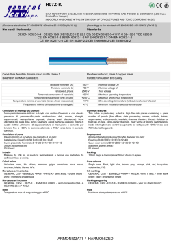
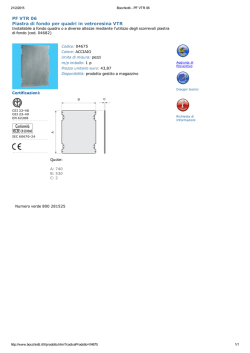
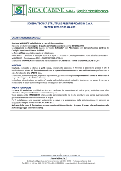
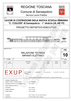
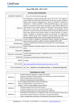
Media tensione secondaria - Secondary medium voltage
DY 800
Quadri MT fino a 24 kV omologato ENEL DY800
MV switchboards up to 24 kV, DY800 ENEL approved
Media tensione secondaria - Secondary medium voltage
DY 800
Quadro MT fino a 24 kV omologato ENEL DY800
MV switchboard up to 24 kV, DY800 ENEL approved
I quadri di Media Tensione DY 800, a tenuta d’arco interno, sono interamente
progettati e realizzati nello stabilimento Boffetti.
Ogni quadro può essere realizzato assiemando i diversi scomparti che sono
normalizzati e quindi intercambiabili. Essi trovano impiego nella distribuzione
elettrica secondaria di media tensione nelle reti di società elettriche e per la
distribuzione di reti industriali.
In particolare possono essere impiegati per cabine di trasformazione e per il comando
e la protezione di linee, di trasformatori di potenza e di motori. Inoltre essendo ogni
scomparto dotato di interruttore può essere impiegato in cabina secondaria per
ripristinare una condizione di normalità, interrompendo e ristabilendo le correnti
di guasto in coordinamento selettivo con l’interruttore di linea installato in cabina
primaria, in sistemi sia a neutro isolato che a neutro compensato.
Lo scomparto ICS prevede un interruttore MT a comando elettrico laterale (INT), un
sezionatore MT di linea (SEZ) con comando manuale, un sezionatore di terra con
comando manuale (ST). Lo scomparto è equipaggiato con dispositivi rilevatori di
tensione secondo la specifica ENEL DY811 con relativi partitori capacitivi DJ1054.
Lo scomparto può essere fornito con il dispositivo RGDAT DY1059 omologato Enel
completamente installato.
Medium voltage switchboards DY 800, with internal arcs withstand characteristic,
are fully designed and manufactured at the Boffetti factory. Each switchboard is
manufactured by assembling various standardized compartments and therefore
are interchangeable. These are used in the medium voltage secondary distribution
system of electric utilities and for distribution in industrial distribution systems.
In particular, these may be used for sub-stations and for the control and protection
of lines, power transformers and motors.
Moreover, since each compartment is equipped with circuit breaker, these may be
used in secondary sub-stations to reinstate normal conditions, by interrupting and
reclosing after fault conditions, by means of selective coordination with the line circuit
breaker installed in the primary sub-station, both in systems with isolated neutral and
with compensated neutral. The ICS compartment is provided with an MV circuit
breaker with controls located on its side (INT), a MV line switch disconnector with
manual control (SEZ) and an earthing switch with manual control (ST).
The compartment is equipped with voltage detectors in accordance with the
ENEL specification DY811, with capacitive voltage dividers type DJ1054.
The compartment may be equipped with a completely installed, Enel approved
RGDAT DY1059 device.
NORME E PRESCRIZIONI
Lo scomparto DY 800 è stato realizzato in rispondenza alle norme IEC 62271-200
ed alla specifica tecnica Enel DY 800 “Apparecchiature Prefabbricate 24 kV con
involucro metallico a tenuta d’arco interno con interruttore (ICS)” ed alle Norme
CEI EN 60694, CEI EN 62271-102, CEI EN 62271-200,
CEI EN 60529, CEI EN 60447 e CEI EN 62271-100.
STANDARDS AND REQUIREMENTS
The compartment DY 800 is built in accordance with the IEC 6227-200 standard, the
Enel technical specification DY800 “24 kV Prefabricated equipment with metallic
enclosures with internal arcs withstand characteristic, with circuit breaker (ICS)”
and with the following standards: CEI EN 60694, CEI EN 62271-102, CEI EN 62271200, CEI EN 60529, CEI EN 60447 e CEI EN 62271-100.
CONDIZIONI DI SERVIZIO
Limiti della temperatura ambiente:
• temperatura non superiore a 40°C con valore medio,
riferito ad un periodo di 24 h, non superiore a: 35 °C
• temperatura minima per installazione all’interno: -15 °C
OPERATING CONDITIONS
The limit of temperature are:
• ambient temperature not exceeding 40°C with an average value,
referred to a period of 24 h, not exceeding 35 °C
• minimum temperature for indoor installation: -15 °C
SICUREZZA
Boffetti dedica molta attenzione alla sicurezza del personale
che può intervenire sulle apparecchiature per manovre e manutenzioni. Questa viene garantita grazie ad una serie di accorgimenti:
• l’involucro dello scomparto, le masse degli apparecchi
e dei componenti vengono messi a terra.
• La continuità dei circuiti di protezione.
• Gli Interblocchi meccanici garantiscono l’esatta sequenza delle manovre.
• Grado di protezione IP3X sull’involucro esterno e IP2X per i diaframmi
delle celle contro contatti con parti in tensione o in movimento.
• Impiego di materiali isolanti affidabili con linee di fuga adeguate
anche per ambienti fortemente inquinati. Impiego di materiali
ad alto grado di autoestinguenza e atossicità.
• Struttura rinforzata che resiste alle sovrapressioni dovute all’arco
• Canalizzazione dei gas di scarico in zone non pericolose
per il personale.
SAFETY
Boffetti pays utmost attention to the safety of personnel who may handle the
switchboard for operations or maintenance purposes.
This is ensured, thanks to a series of measures:
• earthing of the metallic enclosure, the body of the equipment
and components
• continuity of the protection circuit
• mechanical interlocks that ensure the correct operation sequence;
• an IP3X degree of protection for the outside enclosure and IP2X
protection for the cubicle partitions against contact with live or moving parts • use of reliable insulating materials with creepage distance suitable
for highly polluted environments. Use of materials with high degree
of self-extinguishing and non toxic properties
• reinforced structure that can withstand overpressures due to the arc
• ducts leading the discharge gas to zones which are not dangerous
for the personnel
Media tensione secondaria - Secondary medium voltage
DY 800
CARATTERISTICHE DEL COMANDO DELL ’INTERRUTTORE
Il comando dell’interruttore è realizzato, come da specifiche DY1050 e DY1537,
tipo “A”, tenendo conto degli interblocchi meccanici ed elettrici, e delle
caratteristiche riportate nei paragrafi seguenti.
Il comando è dotato di “dispositivo indicatore di posizione sicuro” per l’indicazione della reale posizione dei contatti mobili principali dell’interruttore e
dei sezionatori. Nel comando dell’interruttore è inserito un contamanovre, non
azzerabile e con numeratore a cinque cifre, delle sole manovre di apertura.
Il contamanovre è visibile sul fronte dello scomparto.
CHARACTERISTICS OF THE CIRCUIT BREAKER CONTROL
The circuit breaker control is carried out, in accordance with the specifications
DY1050 and DY1537, type “A”, taking into account the mechanical and electrical interlocks and the characteristics as given in the following paragraphs.
The control mechanism is provided with a “safe position indicator device” for
the indication of the actual position of the main mobile contacts of the circuit
breakers and the disconnecting switches. A non-resettable opening operations
counter with 5 digits is incorporated in the control mechanism.
The operations counter is visible from the compartment’s front.
COMANDO ELETTRICO
Le caratteristiche del comando elettrico dell’interruttore MT
sono le seguenti:
• Tensione nominale di alimentazione ausiliaria: 24 Vcc
• Assorbimento massimo (1) : 300 W
• Tempo di ricarica molle: max 30 s
(1) Escluso il picco di spunto
ELECTRICAL CONTROL
The characteristics of the electrical control mechanism of the MV circuit
breakers are as follows: • Rated voltage of the auxiliary power supply: 24 V dc
• Maximum power consumption (1): 300 W
• Spring charging time: max 30 s
(1) Excluding the peak at starting
Le connessioni con l’unità periferica di telecontrollo, il tipo di connettore e la
piedinatura, sono conformi a quanto prescritto dalla norma Enel DY1050.
I telecomandi di chiusura e apertura, e i telesegnali di stato si riferiscono
all’interruttore.
Sul fronte del quadro sono presenti i pulsanti di apertura elettrica (tasto colore
verde) e di chiusura (tasto colore rosso), e sono visibili gli indicatori di stato
dell’interruttore.
The connections with the peripheral remote control units, the type of connectors
and the pin configuration are in compliance with Enel DY1050 specifications.
The remote closing and opening and the remote signalling of the status are
referred to the circuit breaker.
Push buttons for electrical opening (green button) and closing (red button) are
provided on the switchboard front, where the circuit breaker status indicators
are also present.
COMANDO MANUALE
Sono presenti i comandi di apertura (verde), e di chiusura (rosso), che consentono la manovra di apertura e chiusura dell’interruttore senza avvalersi dell’ausilio
di circuiti elettrici. Tale comando è accessibile dal fronte dello scomparto ed è
dotato di protezione contro le pressioni accidentali.
E’ incluso un sistema completo per il ripristino dell’accumulo di energia
dell’interruttore in assenza di tensione ausiliari.
MANUAL CONTROL
Open (green) and close (red) controls, to allow the opening and closing operation of the circuit breaker without the auxiliary electrical circuit, are also
provided. This control is accessible from the front of the compartment and is
provided with a protection against accidental touching.
A system for the recharging of the stored energy mechanism of the circuit breaker in case of failure of auxiliary power supply, is also provided.
Media tensione secondaria - Secondary medium voltage
DY 800
Involucro e dimensioni
Lo scomparto DY 800 è stato realizzato in due dimensioni, involucro con
larghezza 500 mm ed involucro larghezza 700 mm in funzione dell’impiego. Nei
disegni in calce al catalogo sono evidenziate le diverse dimensioni e tipologie.
CASE and dimensions
The DY 800 panel is manufactured in two sizes: enclosures with a width of
500 mm and 700 mm, depending on the use. In the drawings, the different
dimensions and types are highlighted.
Caratteristiche comuni dell ’involucro
L’involucro metallico è a struttura portante, opportunamente rinforzata con
lamiera di spessore pari a 2 mm.
L’involucro inoltre è realizzato in modo da assicurare all’operatore una sufficiente
protezione in caso di guasti interni (tra le fasi o verso terra), in conformità con la
norma CEI EN 62271-200 (a prova di arco interno, classe di accessibilità A). Le
giunzioni e gli accoppiamenti delle strutture sono realizzate mediante bulloni,
rivetti zincati o saldature.
E’ stata utilizzata lamiera prezincata, tipo UNI EN 10142 con spessore di
rivestimento 200 g/m2, per le parti non visibili dall’esterno e per il pannello
posteriore.
Common characteristics of the case
The enclosure is self supporting, adequately reinforced, with sheet steel
thickness of 2mm.
Moreover, the enclosure is manufactured in such a manner so as to ensure the
operator sufficient protection in case of internal faults (between the phases
and to earth), in accordance with the CEI EN 62271-200 standard (resistant to
internal arcs, accessibility class A).
The joints and the fastening of the structures are made by bolts, galvanized
rivets or welding. Pre-galvanized sheets of type UNI EN 10142 with a coating
thickness of 200 g/m2, not visible externally and for the rear panels, have been
used.
In particolare l’involucro ha:
• due aperture laterali della cella sbarre per il passaggio dei conduttori di
sbarra predisposte per la chiusura dall’esterno con pannello intercambiabile;
• un pannello frontale di chiusura della cella sbarre smontabile dall’esterno;
• un pannello di copertura della cella sbarre smontabile dall’esterno;
• una porta frontale di accesso alla cella apparecchiature;
• un pannello a pavimento realizzato in due elementi smontabili dall’interno,
dotato di tre fori per il passaggio di cavi con diametro massimo di 45 mm,
muniti di cono passacavo in gomma. I fori sono praticati in posizione
centrale, disposti a triangolo e distanziati in maniera tale da rendere
agevole l’installazione di TA dal diametro interno massimo di 150 mm.
Il pannello ha il grado di protezione IP2X.
• due bulloni di messa a terra;
• due golfari maschi M12 per il sollevamento dello scomparto,
disposti in diagonale sulla parte superiore;
• un supporto per terminali di cavo;
• 16 forature asolate (otto per lato) per l’accoppiamento laterale
con altri scomparti (DY800/3);
• 4 fori a pavimento.
In particular, the case has :
• two side openings on the bus-bar compartment for the passage
of the bus-bars with provision for closing from outside, by means
of interchangeable panel;
• a front closing panel for the bus-bar compartment,
which can be dismantled from outside;
• a cover panel for the bus-bar compartment,
which can be dismantled from outside;
• a front access door to the equipment compartment;
• a floor panel made of two elements which can be dismantled from inside,
provided with three holes for the passage of cables with a maximum
diameter of 45 mm, equipped with rubber cable entry cones.
The holes are made at the centre, in a triangular configuration,
with appropriate distances in order to provide easy access for the
installation of CTs, having a maximum internal diameter of 150 mm.
The panel has an IP2X degree of protection.
• 2 earthing bolts;
• two male lifting eyebolts of size M12 for the lifting of the compartment,
arranged in diagonal position on the upper part;
• a support for the cable terminations;
• 16 slotted holes (eight nos. on each side) for connecting side-ways
to other compartments (DY800/3);
• 4 holes on the floor.
Il pannello di copertura (tetto dello scomparto), smontabile dall’esterno,
e il pannello di chiusura frontale della cella sbarre, sono fissati mediante viti o
dadi. In corrispondenza degli angoli dell’involucro stesso sono previsti
degli elementi di rinforzo che garantiscono il mantenimento della squadratura
dello scomparto quando il tetto viene rimosso per consentire il montaggio
delle connessioni. La parete posteriore dello scomparto e le pareti laterali della
cella apparecchiature sono fisse e pertanto sono rivettate alla struttura.
The top covering panel (roof of the compartment), which can be dismantled
from outside, and the front closing panel of the bus-bar compartment,
are fastened by bolts or nuts.
At the corners of the enclosure, reinforcements are provided to avoid deformation of the compartment when the roof is removed for carrying out the
connections.
The rear panel of the compartment and the side panels of the equipment compartment are fixed and therefore are riveted to the structure.
Media tensione secondaria - Secondary medium voltage
DY 800
SEGREGAZIONE SBARRE (DIAFRAMMA)
è prevista una segregazione tra cella sbarre e cella terminali cavi MT; tale
segregazione garantisce, oltre al grado di protezione IP 2X, il rispetto di quanto
previsto dalla norma CEI EN 62271-200, tenendo presente che l’operatore può
accedere alla cella terminali cavi MT a porta dello scomparto aperta.
Lo scomparto è realizzato in maniera tale che i gas di un eventuale arco interno
che si verifichi nel compartimento apparecchiature o nel compartimento sbarre
vengano espulsi verso l’esterno senza interessare direttamente l’altro compartimento.
BUS-BAR SEGREGATION (DIAPHRAGM)
A segregation is provided between the bus-bar compartment and the MV cable
termination compartment; this segregation provides, in addition to a degree of
protection of IP 2X, compliance to the standards CEI EN 62271-200, keeping in
mind that the operator may access the MV termination compartment while the
compartment door is open. The compartment construction is such that gases
released due a possible internal arc originating in the equipment compartment
or in the bus-bar compartment are expelled outside without affecting directly
the other compartments.
CARATTERISTICHE PARTICOLARI SCOMPARTI TIPO ENEL DY800/2
Gli scomparti enel DY800/2 sono destinati all’installazione nelle cabine in
elevazione in installazione singola e non sono accoppiabili con altri scomparti.
PARTICULAR CHARACTERISTICS of the TYPE ENEL DY800/2 COMPARTMENT
The ENEL DY800/2 compartments are meant for sub-stations in elevation, as
a stand-alone installation and cannot be connected to other compartments.
Dispositivo per l’arrivo cavi dall ’alto.
Gli scomparti Enel DY800/2 sono dotati di un dispositivo per l’arrivo di cavi
di media tensione dalla parte superiore dell’apparecchiatura. Esso è costituito
da un pannello metallico munito di tre isolatori passanti a cono esterno isolati
in aria, compatibili con i terminali sconnettibili tipo DJ4155, posizionati in
maniera tale da rispettare le distanze fra le fasi e tra fasi e terra prescritte.
Tale accessorio sostituisce il normale pannello superiore di chiusura della cella
sbarre. Il collegamento fra i terminali interni dei coni e quelli dello scomparto è
realizzato con sbarre rigide opportunamente sagomate.
L’imballaggio è curato in modo tale da impedire il danneggiamento dei coni
durante il trasporto.
Device for cable connections from the top.
The compartments Enel DY800/2 are equipped with a device for incoming MV
cables from the top of the equipment. This consists of a metallic panel equipped
with three air insulated bushing insulators with external cones, compatible
with the disconnecting type terminals type DJ4155, placed to comply with specified distances between phases and between phase and earth.
This accessory replaces the normal upper closing panel of the bus-bar
compartment. The connections between the internal terminals of the cone and those of the
compartments are made by means of suitably shaped rigid bus-bars. Maximum care is taken while packaging to prevent damages to the cones
during transport.
Dispositivo per l’arrivo cavi dal basso (rialzo).
Gli scomparti Enel DY800/2 sono dotati di un rialzo metallico alto 40 cm, in
grado di sostenere lo scomparto, e che assolve alla funzione di cunicolo
passaggio cavi ove esso sia assente o insufficiente.
Il rialzo è costruito in modo tale da garantire tenuta all’arco interno dello
scomparto (classe di accessibilità A). Tale rialzo ha lo stesso trattamento
anticorrosione (verniciatura) dello scomparto, ed è efficacemente connesso alla
terra dello scomparto. Inoltre il rialzo può essere impiegato per la protezione
dei coni durante il trasporto.
Device for cable connections from the bottom.
The compartments Enel DY800/2 are provided with a metallic enclosure of height 40 cm, able to support the compartment and which also carries
out the function of a cable trench where this is not provided or insufficient.
This enclosure is manufactured to ensure internal arc withstand of the
compartment ( accessibility class A). This enclosure is provided with the same corrosion prevention treatment
(painting) as the rest of the compartment and is solidly connected to the earth
of the compartment.
This enclosure may be used for the protection of the cones during transport.
Media tensione secondaria - Secondary medium voltage
DY 800
INTERBLOCCHI
Gli interblocchi svolgano le seguenti funzioni:
1) Il sezionatore (SEZ) ed il sezionatore di terra (ST) si manovrano
solo con interruttore in posizione di aperto;
tale manovra è permessa da interblocco di tipo meccanico.
2) Il sezionatore di terra (ST) si può chiudere solo a sezionatore di linea (SEZ)
in posizione di aperto con contatto mobile bloccato;
tale manovra è permessa da interblocco di tipo meccanico.
3) l’interruttore (INT) può essere manovrato meccanicamente ed elettricamente
solo a leva non inserita in alcuna sede di manovra e al verificarsi
delle seguenti condizioni:
- il sezionatore (SEZ) è in posizione di chiuso (I) e il sezionatore di terra (ST)
è in posizione di aperto (O), entrambi con contatti mobili bloccati (fine corsa);
- il sezionatore (SEZ) è in posizione di aperto (T) e il sezionatore di terra (ST)
è in posizione di chiuso (T), entrambi con contatti mobili bloccati (fine corsa).
Tale interblocco è realizzato sia meccanicamente che elettricamente
con taglio dei comandi elettrici dell’interruttore;
4) la porta dello scomparto può essere aperta solo in condizioni di sicurezza,
ovvero con sezionatore di linea aperto (T) e sezionatore di terra chiuso (T);
tale manovra è permessa da interblocco di tipo meccanico lucchettabile.
In tutti gli altri casi, l’inserzione del lucchetto è interdetta meccanicamente.
SENSI DI MANOVRA E SEGNALAZIONI
DEI COMANDI DEGLI APPARECCHI
Il senso di movimento per l’esecuzione delle manovre è conforme a quanto prescritto
dalla norma CEI EN 60447. Anche rimuovendo il carter di protezione dei comandi, le
indicazioni dei versi di manovra e dello stato degli apparecchi restano visibili, e gli
interblocchi mantengono inalterata la propria funzionalità.
INTERLOCKS
The interlocks carry out the following functions:
1) The switch disconnector (SEZ) and the earthing switch (ST) can operate
only when the circuit breaker is in the open position;
this condition is ensured by a mechanical interlock.
2) The earthing switch (ST) may be closed only if the line switch disconnector
(SEZ) is in the open position with its mobile contacts blocked;
this condition is ensured by a mechanical interlock.
3) The circuit breaker (INT) may be operated mechanically and electrically only
if the operating lever is not inserted in its hole or if the following
conditions are fulfilled:
- The switch disconnector ( SEZ) is in the closed (I) position
and the earthing switch (ST) is in the open (O) position, both with their
mobile contacts blocked (limit switch);
- The switch disconnector (SEZ) is in the open position (T) and the earthing
switch (ST) is in the closed position (T), both with their mobile contacts
blocked (limit switch). This interlock is carried out both mechanically
and electrically by cutting off the electrical controls to the circuit breaker;
4) The door of the compartment can be opened only under safe conditions, or
when the line switch disconnector is open (T) and the earthing switch is
closed (T); this condition is obtained by a mechanical interlock using padlock. In all the other cases, the insertion of the padlock is blocked mechanically.
OPERATION DIRECTION AND SIGNALLING of control
FOR EQUIPMENTS
The direction of operation while carrying out operations is conform to what is
specified in the CEI EN 60447 standard. Even after removing the protection cover for
controls, the indications for the direction of operation and status of the equipment
remain visible and the interlocks maintain their operational functionality.
PORTA
Il vano della porta dello scomparto ha la maggiore luce netta possibile compatibile
con la soluzione costruttiva adottata; essa è incernierata sul lato sinistro del fronte
scomparto con angolo di apertura di 135°.
La porta è dotata di un congegno di blocco e di una maniglia, ed è interbloccata.
Sulla porta è previsto un finestrino in robusto materiale trasparente, con
schermatura elettrostatica che consente il controllo visivo dall’esterno, eventualmente con l’ausilio di torcia elettrica.
Sulla porta degli scomparti è prevista un’apertura che consente il passaggio
dei conduttori per le prove di ricerca guasti dei cavi MT, ubicata nella posizione
indicata nella tabella di unificazione degli scomparti.
Questa apertura ha dimensioni pari a 150x150 mm ed è chiusa mediante sportello
imbullonato, apribile solo dall’interno dello scomparto. I bordi dell’apertura
sono dotati di apposita guarnizione in modo da evitare il danneggiamento dei
conduttori durante le prove di ricerca guasti.
DOOR
The compartment door has a higher net clear space compatible with the
constructional solution adopted; this is hinged at the left of the front compartment with an opening angle of 135°C.
The door is equipped with a blocking device and a handle, and is interlocked.
A window made of robust, transparent material, with electrostatic screen, that
allows visual inspection from outside, if required with the help of an electric torch
light, is provided. On the door of the compartments, an opening which allows
the passage of cables for the MV cable fault locator, installed in the position as
shown in the standard tables for the compartments, is provided.
This opening has a dimension of 150 mm x 150 mm and is closed by a bolted
window, which can be opened only from the inside of the compartment. The
edges of the openings are provided with proper gaskets to avoid damage
to the cables during fault location testing.
RIVELATORI PRESENZA TENSIONE
Lo scomparto è equipaggiato con i rivelatori di presenza tensione DY811
e con i relativi partitori capacitivi DJ1054 omologati.
VOLTAGE DETECTOR
The compartment is equipped with a voltage detector DY811 and with the related
standardised capacitor divider type DJ1054.
Media tensione secondaria - Secondary medium voltage
DY 800
CONNESSIONE DEL CIRCUITO PRINCIPALE
In ottemperanza al punto 5.3.1 della norma CEI EN 62271-200 tutte le parti
del circuito principale alle quali è necessario o può essere possibile accedere
possono essere messe a terra prima di diventare accessibili.
Le sbarre per il collegamento degli scomparti, gli attacchi di connessione
ed i conduttori di collegamento dei circuiti principali rispondono a quanto
prescritto nella tabella Enel DY810 per le tipologie DY800/1 e DY421
per il DY800/3. Dove sono presenti collegamenti in treccia di rame piatta flessibile,
questi sono di sezione minima 150 mm2, tali da non presentare il rischio
di diminuire le distanze di isolamento a seguito di spostamento o deformazioni.
Tutta la bulloneria impiegata per le connessioni dei circuiti principali
è protetta con zincatura elettrolitica Fzn III UNI 3740.
ISOLATORI
Gli isolatori portanti presenti nello scomparto, di tipo unificato e omologato,
(tab. DJ 1056 e DJ 1054) e tutti gli isolatori portanti e passanti isolati in aria
impiegati hanno una linea di fuga minima di 350 mm.
IMPIANTI DI TERRA
L’impianto di terra interno dello scomparto è realizzato con piatto di rame Cu-ETP
UNI 56491-71 di sezione 75 mm2 e fa capo ai bulloni di terra previsti nelle tabelle
DY411 e DY809.
Sono direttamente collegati all’impianto di terra i morsetti di terra dei vari
apparecchi e la porta della cella apparecchiature; inoltre sono collegati a terra
gli organi mobili di comando e le altre masse metalliche.
I collegamenti tra parti fisse e parti mobili sono realizzati con conduttori flessibili
di rame di sezione non inferiore a 30 mm2.
Sul supporto dei terminali di cavo degli scomparti linea, le connessioni di terra per
la messa a terra delle schermature metalliche dei cavi sono realizzate utilizzando
uno dei due bulloni o viti di fissaggio di ciascun terminale e l’elemento
di connessione di cui i terminali DJ 4453 sono corredati.
Il collegamento di terra esterno tra gli scomparti è realizzato mediante barre
di rame unificate (cfr. tab. DY 421 e DY810) connesse ai bulloni di terra riportati
nelle tabelle DY411 e DY809.
RIVESTIMENTI PROTETTIVI
Tutte le parti in materiale ferroso degli apparecchi elettrici non preventivamente
omologati dall’ENEL montati negli scomparti, sono protetti con zincatura
elettrolitica Fe/Zn 12C UNI ISO 2081 e UNI ISO 4520.
Per le molle realizzate in acciaio ad alta resistenza sono utilizzati rivestimenti
chimici a base di zinco noti con il nome commerciale di DACROMET.
La bulloneria di assiemaggio ed i piccoli accessori in materiale ferroso,
se non diversamente prescritto nelle tabelle di unificazione, sono protetti
con zincatura elettrolitica Fzn III UNI 3740 parte 6.
MAIN CIRCUIT CONNECTION
In compliance with point 5.3.1 of the standard CEI EN 62271-200, it shall be
possible to earth, all the main circuit parts to which access is required or to which access is possible, before they become accessible. The bus-bars for the connection
of the compartments, the connectors and the connecting conductors of the main
circuits comply with what is specified in the ENEL DY 810 table for the type
DY800/1 and DY421 for the type DY800/3. Where flexible braided copper
connections are used, these shall have a minimum cross section of 150 mm2,
in order to avoid the risk of reducing the insulation distance upon movement
or deformation. All fasteners used for the connection of the main circuits
are protected by means of electrolytic galvanizing Fzn III UNI 3740.
INSULATORS
The post insulators provided in the compartments, of the standardized
and approved type ( table DJ1056 and DJ1054) and all the air insulated post
and bushing insulators have a minimum creepage distance of 350 mm.
EARTHING SYSTEMs
The earthing system inside the compartment consists of a copper plate Cu-ETP
UNI 56491-71 of cross section 75 mm2 and is connected to earthing bolts as given
in tables DY411 and DY809.
The earthing terminals of the various equipment and the doors of the equipment
compartments are directly connected to the earthing system; moreover, the moving
parts of the control mechanism and other metallic enclosures are also connected
to the earth. The connections between fixed parts and mobile parts are made
using flexible conductors of cross section not less than 30 mm2. On the support
of the cable terminals in the line compartments, the earthing connections
for the earthing of the metallic screens of the cables, are made, by using
one of the two bolts or fixing screws of each terminal and the connection terminal
which is provided in DJ 4453 type terminations.
The external earthing connections between the compartments is made by using
standardized copper bars (see tab. DY 421 and DY810) connected to earthing bolts
as given in the tables DY411 and DY809
PROTECTIVE COATINGs
All ferrous metallic parts of the electrical equipment which
are not standardized beforehand by ENEL and installed in the compartments,
are protected by electrolytic galvanizing Fe/Zn 12C UNI ISO 2081 e UNI ISO 4520.
For the springs made of high resistance steel, zinc based chemical coating
known under the trade name DACROMET is used. Fasteners
and miscellaneous accessories in ferrous materials, if not otherwise specified
in the approved standard table, are protected with electrolytic
galvanizing Fzn III UNI 3740 part 6.
Media tensione secondaria - Secondary medium voltage
DY 800
COMANDO MANUALE DEL SEZIONATORE
E DEL SEZIONATORE DI TERRA
Il comando manuale del sezionatore di linea (SEZ) e del sezionatore di terra (ST)
è del tipo a moto rotativo, conforme alla norma CEI EN 60447.
Le manovre possono essere effettuate applicando un momento non superiore
a 200 Nm. La leva di comando si innesta nella propria sede applicando nella
direzione di inserzione una lieve forza, atta a vincere la resistenza di una molla
che a manovra ultimata, favorisce l’estrazione della stessa.
Il grado di protezione delle sedi di manovra e degli organi di comando è IP3X.
Non è possibile estrarre la leva, prima che la manovra sia completata.
Il comando del sezionatore di linea è a manovra manuale dipendente.
MANUAL CONTROL MECHANISM OF DISCONNECTOR
AND EARTHING SWITCH
The manual control mechanism of the line disconnector (SEZ)
and the earthing switch (ST) are of the rotary motorized type in compliance
with the standard CEI EN 60447. The operations may be carried out by applying
a moment not greater than 200 Nm. The operating handle can be inserted into
its hole by applying a light pressure in the direction of insertion,
to overcome the resistance of a spring, which upon completion
of the operation, helps the removal of the same. The degree of protection
of the operating hole and the control mechanism is IP3X. It is not possible
to withdraw the handle, before the completion of the operation.
The operation of the line disconnector switch is of the dependent manual type.
DISPOSITIVO RGDAT
è predisposta sul fronte dello scomparto una piastra metallica idonea
all’installazione del dispositivo RGDAT DY1059.
Nel caso di fornitura del dispositivo, questo sarà installato sulla piastra
suddetta, i trasformatori di corrente saranno fissati sul fondo delle scomparto
ed il connettore esapolare sul fronte dello scomparto in maniera idonea
al trasporto senza danneggiamenti.
Sono fornite le lampadine di presenza tensione.
RGDAT DEVICE
A metallic plate suitable for the installation of the RGDAT DY1059 device
is provided on the front of the panel. The RGDAT device, when provided,
it will be installed on the above plate, the current transformers will be fixed
to the rear of the compartment and the 6 pole connector on the front of the
compartment in a manner suitable for transport without damage.
Voltage presence indication lamps are also provided.
PROVE
Sullo scomparto sono effettuate, per quanto applicabile, le prove riportate
riferite alle prescrizioni di collaudo dei quadri DY1100 e alle prescrizioni
di collaudo degli interruttori MT DY1501.
Sono inoltre state eseguite le seguenti prove di tipo:
• Il sezionatore di terra ST viene sottoposto alla prova di stabilimento in corto
circuito secondo quanto sancito dalla norma CEI EN 62271-102 art. 6.101.
• I sezionatori hanno superato, a seconda del tipo di apparecchio, le prove
di cui al punto A.6 della norma CEI EN 62271-102.
TESTS
The tests mentioned in the test requirements for DY1100 switchboards
and in the requirements for the testing of circuit breakers MT DY1501,
shall be carried out, as far as applicable.
Further, the following type tests have also been carried out:
• The earthing switch ST is subject to fault making tests according
to what is given in the standard CEI EN 62271-102 art. 6.101.
• The earthing switches have passed, according to the type of equipment,
the tests as given in the point A.6 of the standard CEI EN 62271-102.
Media tensione secondaria - Secondary medium voltage
DY 800
Caratteristiche nominali del quadro:
switchboard Rated specifications:
Tensione nominale / Rated voltage 24 kV
Livello di isolamento nominale, tensioni di tenuta
Rated insulation level, withstand voltages
Tensione di tenuta ad impulso atmosferico verso terra e tra le fasi /
lightning impulse withstand voltage towards ground and between phases
125 kV
Tensione di tenuta ad impulso tra i contatti aperti del sezionatore /
lightning impulse withstand voltage between the open contacts of the circuit breaker
145 kV
Tensione di tenuta a frequenza industriale verso terra e tra le fasi /
power frequency withstand voltage towards ground and between phases
50 kV
Tensione di tenuta a frequenza industriale tra i contatti aperti del sezionatore/
power frequency withstand voltage between the open contacts of the circuit breaker
60 kV
Frequenza nominale / Rated frequency 50 Hz
Corrente nominale in servizio continuo per le sbarre /
Rated current of the bars in continuous duty mode
400 A
Corrente nominale ammissibile di breve durata per le sbarre e per le derivazioni /
Permitted short-term current for bars and shunts
12,5 kA
Valore di cresta della corrente ammissibil di breve durata per le sbarre e per le derivazioni /
Permitted short-term peak current for bars and shunts
31,5 kA
Durata nominale del corto circuito / Rated length of short-circuit
Grado di protezione esterno / Outdoor protection class
Arco interno / Internal arc
Classificazione IAC (arco interno) / IAC rating (internal arc)
(1) Compreso il pannello di sfogo delle sovrapressioni /
Including the overpressure discharge panel
(2) Per DY802/2 e DY802/216 la classe è AFL /
For models DY802/2 and DY802/216, the class is AFL
1s
IP 3X (1)
12,5 kA per- for 0,5 s
AF
(2)
Media tensione secondaria - Secondary medium voltage
DY 800
Caratteristiche DELL’INterruttore MT (INT):
CHARACTERISTICS OF THE MV CIRCUIT BREAKER (INT):
Tensione nominale / Rated voltage 24 kV
Tensione nominale di tenuta ad impulso atmosferico /
Rated lightning impulse withstand voltage
125 kV
Frequenza nominale / Rated frequency 50 Hz
Corrente termica nominale / Rated thermal current
400 A
Corrente nominale ammissibile di breve durata per le sbarre e per le derivazioni /
Permitted short-term current for bars and shunts
Classe di durata elettrica (rif. Tab UE DY1501) /
Dielectric strength class (ref. table UE DY1501)
12,5 kA
P
Valore di cresta della corrente ammissibile di breve durata per le sbarre e per le derivazioni /
31,5 kA
Permitted short-term peak current for bars and shunts
Durata nominale del corto circuito / Rated length of short-circuit
1s
Potere d’interruzione nominale in corto circuito / Rated short-circuit cut-off current
12,5 kA
Sequenza di manovre nominale / Rated sequence of operations
O - 0,3 sec - CO - 30 sec - CO
Durata nominale del corto circuito / Rated length of short-circuit
1s
Vita meccanica / Mechanical life cycle
10000 manovre - operations
Correnti di interruzione nominale / Rated cut-off currents
di un circuito prevalentemente attivo / of a prevalently active circuit
di un trasformatore a vuoto / of a transformer, off-load
di linea a vuoto / of a line, non charging
di cavo a vuoto / of a cable, non charging
L’interruttore è del tipo ad esecuzione fissa con comando laterale.
Per quanto non specificato, l’interruttore è conforme alle norme CEI EN 62271-100.
The circuit breaker is of the fixed execution type with controls on the side.
Where not specified, the circuit breaker is in compliance
with the standard CEI EN 62271-100.
400 A
6,3 A
10 A
16 A
Media tensione secondaria - Secondary medium voltage
DY 800
CARATTERISTICHE
SEZIONATORE CON COMANDO MANUALE (SEZ) :
CHARACTERISTICS OF THE DISCONNECTOR SWITCH
WITH MANUAL CONTROL (SEZ):
Corrente nominale / Rated current
Corrente di breve durata nominale ammissibile / Permitted short-term rated current
Corrente nominale ammissibile di cresta / Permitted rated peak current
Durata ammissibile nominale del corto circuito / Permitted rated length of short-circuit
Durata meccanica (classe) / Mechanical resistance (class)
Classe del sezionatore / Class of circuit breaker
400 A
12,5 kA
31,5 kA
1s
M0
E0
Il sezionatore è del tipo a due posizioni (linea-terra).
Il comando delle lame è del tipo manuale; il movimento delle terne dei poli è simultaneo.
The switch disconnector is of the type with two positions (line-earth).
The control of the blade is manual and the movement of the three poles
takes place simultaneously.
CARATTERISTICHE DEL SEZIONATORE DI TERRA (ST):
EARTHING SWITCH (ST) CHARACTERSTICS:
Corrente di breve durata nominale ammissibile / Permitted short-term rated current
12,5 kA
Corrente nominale ammissibile di cresta / Permitted rated peak current
31,5 kA
Potere di stabilimento in corto circuito / Short-circuit making capacity
31,5 kA
Numero di stabilimenti di correnti in corto circuito / Number of short-circuit making currents
2
Durata ammissibile nominale del corto circuito / Permitted rated length of short-circuit
1s
Durata meccanica (classe) / Mechanical resistance (class)
M0
Classe del sezionatore / Class of circuit breaker
E1
Il sezionatore di terra ha le lame in posizione di chiuso
ben visibili a porta aperta.
The blades of the earthing switch in closed position,
are clearly visible when the door is open.
DY 800
Modelli e dimensioni - Types and dimensions
DY 800/1
Cod. 162410
Cod. 162413
Cod. 162420
Cod. 162423
Cod. 162430
Cod. 162433
DIMENSIONI E PESI - DIMENSIONS AND WEIGHTS
Larghezza / Width
Altezza / Height Profondità / Depth
500 mm
1850 mm
1050 mm
Peso / Weight
330 kg
DY 800/2
DIMENSIONI E PESI - DIMENSIONS AND WEIGHTS
Larghezza / Width
Altezza / Height Profondità / Depth
500 mm
2250 mm
1050 mm
Peso / Weight
380 kg
DY 800/3
DIMENSIONI E PESI - DIMENSIONS AND WEIGHTS
Larghezza / Width
Altezza / Height Profondità / Depth
Peso / Weight
700 mm
1950 mm
1150 mm
375 kg
© Copyright 2026 Paperzz